EP3148761B1 - Formbehälterteil zur herstellung von ziegelriemchen, formbehälterpressvorrichtung und verfahren zur anwendung davon - Google Patents
Formbehälterteil zur herstellung von ziegelriemchen, formbehälterpressvorrichtung und verfahren zur anwendung davon Download PDFInfo
- Publication number
- EP3148761B1 EP3148761B1 EP15732477.3A EP15732477A EP3148761B1 EP 3148761 B1 EP3148761 B1 EP 3148761B1 EP 15732477 A EP15732477 A EP 15732477A EP 3148761 B1 EP3148761 B1 EP 3148761B1
- Authority
- EP
- European Patent Office
- Prior art keywords
- parts
- mould
- mould container
- brick
- slip
- Prior art date
- Legal status (The legal status is an assumption and is not a legal conclusion. Google has not performed a legal analysis and makes no representation as to the accuracy of the status listed.)
- Active
Links
Images


Classifications
-
- B—PERFORMING OPERATIONS; TRANSPORTING
- B28—WORKING CEMENT, CLAY, OR STONE
- B28B—SHAPING CLAY OR OTHER CERAMIC COMPOSITIONS; SHAPING SLAG; SHAPING MIXTURES CONTAINING CEMENTITIOUS MATERIAL, e.g. PLASTER
- B28B5/00—Producing shaped articles from the material in moulds or on moulding surfaces, carried or formed by, in or on conveyors irrespective of the manner of shaping
- B28B5/02—Producing shaped articles from the material in moulds or on moulding surfaces, carried or formed by, in or on conveyors irrespective of the manner of shaping on conveyors of the endless-belt or chain type
- B28B5/021—Producing shaped articles from the material in moulds or on moulding surfaces, carried or formed by, in or on conveyors irrespective of the manner of shaping on conveyors of the endless-belt or chain type the shaped articles being of definite length
- B28B5/022—Producing shaped articles from the material in moulds or on moulding surfaces, carried or formed by, in or on conveyors irrespective of the manner of shaping on conveyors of the endless-belt or chain type the shaped articles being of definite length the moulds or the moulding surfaces being individual independant units and being discontinuously fed
-
- B—PERFORMING OPERATIONS; TRANSPORTING
- B28—WORKING CEMENT, CLAY, OR STONE
- B28B—SHAPING CLAY OR OTHER CERAMIC COMPOSITIONS; SHAPING SLAG; SHAPING MIXTURES CONTAINING CEMENTITIOUS MATERIAL, e.g. PLASTER
- B28B7/00—Moulds; Cores; Mandrels
- B28B7/14—Moulds with means incorporated therein, or carried thereby, for cutting the moulded article into parts
Definitions
- the invention relates to a mould container part for the manufacture of brick slips, a mould container pressing device provided with such a mould container part, and to a method for applying a mould container pressing device with such a mould container part.
- brick slips When brick slips are arranged on a wall, this wall will acquire the visual appearance of a wall erected from bricks. Brick slips are therefore applied for the purpose of embellishing flat walls.
- Brick slips are conventionally manufactured by sawing a fired brick into strips. This method has several drawbacks. A large quantity of waste material is thus created during sawing, and the sawing results in noise and dust emission. In addition, the saws and the sawing machines are subject to wear. Another regular occurrence is that a brick wholly or partially breaks during the sawing and becomes unusable. The whole brick, including all the waste material, has undergone a complete drying and firing process, and this costs time and energy. The energy consumed in respect of the waste material is wasted. Finally, this conventional sawing method is labour-intensive.
- DE-A1-3400380 discloses a moulding container pressing device with a mould conveyor, the mould containers of which are formed from two halves which are attached to each other for pivoting around a pivot axis and which fold open for the purpose of releasing the green bricks when the mould conveyor runs over a sprocket.
- NL-A2-6913272 discloses a method for manufacturing moulded bricks, wherein the green bricks are cut into pieces, each the size of a brick, in their mould containers prior to drying.
- EP-A1-2085199 in the name of applicant shows a mould container part wherein a plate is arrangeable against a side wall of the mould container in order to influence the size of the green brick to be formed in the mould container.
- An object of the present invention is to provide a mould container pressing device and method for application thereof wherein the stated drawbacks do not occur, or at least do so to lesser extent.
- brick slips With the thickness of a half-brick to arrange a single cross-sectional opening in the middle of the green brick, brick slips normally have narrower dimensions.
- a second cross-sectional opening is arranged in the side walls of the mould containers. In addition to increasing the production capacity, this has the further advantage that the mould container is sufficiently wide to enhance repeated and complete filling of the mould container with clay.
- the mould container part according to the invention it is possible to use filling means of a traditional mould container pressing device for conventional bricks.
- the green brick formed by these filling means is after all only brought to the desired thickness of the brick slips by dividing the green brick after the moulding.
- conventional filling means tested and reliable techniques can on the one hand be used.
- Direct pressing of a green brick with the small thickness of a brick slip causes problems, such as the difficulty of filling the mould container.
- conventional filling means a brick slip will on the other hand be obtained which exactly corresponds visually to a standard brick formed with such filling means. A wall covered with such brick slips cannot therefore be distinguished visually from a wall erected from bricks.
- each green brick can provide two bricks slips at a time, the production capacity which such a mould container part can provide is moreover doubled compared to a conventional mould container pressing device.
- mould container part provides green brick parts in the size of a brick slip, whereby only the net product need be subjected to a drying and firing process. Because these green brick parts are much thinner than a green brick for a conventional brick, it will moreover be possible for this drying and firing process to proceed more quickly and consume less energy.
- the slip moulding parts face toward each other in the filling position and form walls of the mould container, wherein the at least two slip moulding parts movable relative to each other are pivotable relative to each other between the situation in which they face toward each other in the filling position and in which they form walls of the mould container and the release position in which the slip moulding parts comprise a substantially lying orientation.
- a mould container of conventional dimensions i.e. similar to a green brick for a traditional brick, is thus formed in the filling position.
- the walls of the traditional brick will form the walls of the green brick part, and thereby the visual side of the final brick slip.
- the substantially lying orientation is defined in the lying part of the conveyor of the mould container pressing device.
- the cutting plane of the green brick part is directed upward here and is suitable in this substantially lying orientation for receiving thereon a drying plate on which the green brick parts can finally be discharged and transported to the drying process and subjected thereto.
- the visual side of the final brick slip is oriented downward and received in the respective slip moulding part.
- the hinges are placed such that the slip moulding parts are pressed toward each other under the influence of the pressure during the pressing, thereby preventing the possibility of the mould container opening under the influence of the pressure.
- a structurally elegant cross-sectional opening is obtained when according to yet another preferred embodiment a first of the two cross-sectional openings is formed in the side walls of the mould container in that the two slip moulding parts of the mould container part movable relative to each other are arranged on two adjacent conveyor parts of a circulating conveyor, and wherein the separation between these conveyor parts forms a first cross-sectional opening in the mould containers.
- one or more slip moulding parts provide at least two protruding parts extending inside a mould container.
- Green brick parts with at least two protruding parts and a recess therebetween provide advantages such as enabling simple and reproducible arrangement on prefab constructions, wherein the protruding parts can for instance be pushed under prearranged hook parts or arranged in other manner. By placing the protruding parts of adjacent brick slips abutting each other a desired spacing can also be obtained for the later arrangement of pointing between adjacent brick slips.
- the at least two parts protruding inside the mould container are arranged some distance from each other against the same wall of the mould container.
- the projecting parts to be formed on the green brick part are hereby interrupted by recesses. These recesses simplify the arrangement of a projecting part of a brick slip under a hook part on a prefab construction because the hook parts can be guided in through the recesses between the projecting parts. A projecting part can then be brought into engagement with a prefab hook part with a small sliding of the brick slip. Such a prefab construction does not form part of this application.
- the protruding parts comprise a longitudinal strip arranged in longitudinal direction of the slip moulding part and/or a transverse strip arranged in transverse direction of the slip moulding part, wherein one or more further protruding parts are provided on the longitudinal strip and/or on the transverse strip.
- These one or more further protruding parts provide the projecting parts which arc to be formed on the green brick part and which are interrupted by recesses.
- the invention further relates to a mould container pressing device for manufacturing brick slips for the brick manufacturing industry, as defined in claim 6.
- the cutting member cuts through the green brick formed in the mould containers at a predetermined distance from the side walls of the mould container formed by the slip moulding parts. This predetermined distance corresponds to the thickness of the green brick part which will eventually form the brick slip following drying and firing.
- the cutting member comprises a substantially flexible endless member.
- a flexible endless member can for instance be a cord which can cut through the still wet clay.
- Such a cord is considerably less expensive than the saws according to the prior art brick slip production techniques which are susceptible to wear.
- a green brick with the size of conventional brick can be manufactured, from which can then be cut narrow green brick parts for the brick slips.
- the green brick to be moulded initially by the mould container pressing device can be shaped into a brick size via a proven and optimized process, after which thin slips can be taken therefrom.
- An important further advantage is that the appearance of the visual side is identical to that of a conventional brick.
- a part of the clay can already be removed and recycled early in the manufacturing process when according to yet another preferred embodiment a discharge member is provided with which clay present in the middle moulding part can be discharged. Only the net product need hereby be subjected to a drying and firing process. Because these green brick parts are much thinner than the green brick of which they formed the side walls, it will moreover be possible for the drying and firing process for the green brick parts to proceed more quickly and consume less energy.
- the discharge member comprises gripping members and/or suction means.
- the holding means comprise at least one spring which is connected to the slip moulding parts and which is configured to force the at least one slip moulding part connected to the at least one spring into the filling position and/or into the release position, and wherein one or more position reversal actuators are provided which are configured to move the slip moulding parts counter to the spring bias from the filling position to the release position, and vice versa.
- the position reversal actuator can for instance comprise a plunger or a cam guide.
- the invention further relates to a method for manufacturing brick slips from clay for the brick manufacturing industry with a mould container pressing device, as defined in claim 11.
- the cutting member can for instance comprise two above described cords which cut through the still wet clay of the green brick.
- the green bricks are preferably cut through simultaneously on two cutting planes by simultaneously displacing a first chord through a first cross-sectional opening and a second cord through a second cross-sectional opening.
- the step of cutting through one or more green bricks formed in the mould containers with a cutting member comprises of cutting through these green bricks in longitudinal direction.
- moving the slip moulding parts from the filling position to the release position comprises of pivoting the slip moulding parts and green brick parts formed therein to a substantially lying orientation.
- a middle moulding part is provided between the slip moulding parts and the method further comprises the step of discharging clay present in the middle moulding part with a discharge member.
- the discharged clay can be recycled and moreover need not be subjected to a drying and firing process.
- a mould container part and/or a mould container pressing device according to the invention are applied.
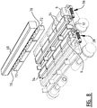
- the mould container pressing device 1 shown in figure 1 comprises a circulating conveyor 24 assembled from a plurality of conveyor parts 26.
- rollers 28 which engage in chain wheels (not shown) whereby conveyor 24 is drivable.
- mould container parts 2 Arranged on conveyor parts 26 of conveyor 24 are mould container parts 2 which will be elucidated in more detail below.
- conveyor 24 Arranged above conveyor 24 is a filling device with which clay is arranged in the mould container parts 2 thereunder.
- Each mould container part 2 has in the shown embodiment four mould containers 4 in which one green brick at a time is mouldable.
- cutting member 52 comprises a cord 56 which runs over two rollers 54 and is tensioned directly above mould container part 2 and cuts thereover.
- this clay waste 58 is picked up with a first discharge conveyor 60 and set down onto a second discharge conveyor 61.
- the clay waste 58 is carried away by second discharge conveyor 61 and preferably reused.
- a second cutting member 62 comprises rollers 64 over which runs a cord 66.
- This cord 66 is displaceable in height direction with second cutting member 62, and as a result of this height displacement the green brick 32 is divided into two green brick parts 34 and surplus clay 72 present between these green brick parts 34.
- This surplus clay is subsequently discharged as clay waste 72 in a further step by a discharge member 68, which for instance comprises gripping members and/or suction means 70, and preferably reused.
- Drying plates 74 are then placed on the green brick parts 34 and, by further rotating the conveyor 24, carried to a position in which drying plates 74 are situated under mould container parts 2. In order to prevent the drying plates falling off, tensioning straps or chains are used which press drying plates 74 against mould container part 2 when they pass over a chain wheel (not shown).
- drying plates 74 When drying plates 74 are situated on the underside of mould container parts 2, they are gradually moved off mould container parts 2 and the green brick parts 34 formed by mould container pressing device 1 will come to lie on drying plates 74. Drying plates 74 with the green brick parts 74 present thereon are then discharged for further treatment.
- the green brick parts 34 are first placed in a drying chamber where they will be dried before being fired to a hard brick in a kiln.
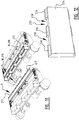
- FIG. 2 shows two successive conveyor parts 26 of conveyor 24, wherein a mould container part 2 is located at the transition between these two conveyor parts 26.
- each mould container part 2 has four mould containers 4 and comprises at least two slip moulding parts 6 movable relative to each other and movable between a filling position (position has shown in figure 2 ), in which green bricks 32 are mouldable, and a release position (as shown in figure 8 and other figures) in which slip moulding parts 6 arc removed from each other and wherein the green brick parts 34 received therein are separated from each other and releasable.
- slip moulding parts 6 In the orientation of slip moulding parts 6 shown in figures 2 , 3 and 4 they face toward each other and form the walls 8 of mould containers 4. This orientation corresponds to the filling position in which green bricks 32 are mouldable in mould containers 4.
- the slip moulding parts 6 movable relative to each other are pivotable relative to each other in that they are each arranged on a pivot shaft 10.
- slip moulding parts 6 When slip moulding parts 6 each rotate about their own pivot shaft 10, they displace from the filling position shown in figures 2 , 3 and 4 to a release position in which slip moulding parts 6 have a substantially lying orientation.
- holding means 38 which can retain these positions.
- the holding means comprise a cam member 40 which rotates around pivot shaft 10 and which is connected with a shaft 48 to a slide member 44.
- the slide member is slidable over a shaft 42 and is biased by a spring 46.
- the spring bias of spring 46 ensures that slip moulding parts 6 are held fixedly in the filling position or in the release position.
- FIG. 3 Shown in the view of figure 3 is how a mould container part 2 extends over two conveyor parts 26.
- Each mould container part 2 is formed from slip moulding parts 6 and a middle moulding part 12 located therebetween.
- the slip moulding parts 6 and the middle moulding part 12 enclose a mould container 4 which corresponds in dimensions to a mould container for for instance conventional bricks.
- conventional bricks are characterized by the much greater thickness compared to a brick slip.
- This proven technique allows highly reliable and good results. Owing to the combination of slip moulding parts 6 and middle moulding part 12 use can thus be made of this proven and fully developed technique, whereby a highly reliable and consistent filling of mould containers 4 is guaranteed.
- Showing conveyor parts 26 in spaced-apart view in figure 4 indicates clearly how each mould container part 2 is divided over two conveyor parts 26.
- An advantage of this setup is that a natural separation is created between a middle moulding part 12 and a slip moulding part 6 through which green brick 32 can be divided, as will be further elucidated with reference to figures 6 and 7 .
- Figure 5 shows the situation in which slip moulding parts 6 are moved from the filling position shown in figure 4 to the release position shown in figure 8 .
- Figure 5 shows an intermediate position in which cam members 40 are operated by position reversal actuators (not shown) and a slide member 44 presses over shaft 42 of holding means 38 counter to the spring bias of spring 46.
- FIG. 1 For the sake of clarity figures 2-5 arc shown without green bricks 32 arranged therein.
- Figures 6 and 7 show how a green brick 32 is divided into green brick parts 34 and possibly surplus clay material 72.
- first cross-sectional opening 18 comprises the separation between two successive conveyor parts 26 of the circulating conveyor.
- Cords 66 will cut through green bricks 32 better by having cords 66 of second cutting number 62 run over rollers 64 and driving them in circulating manner when cutting number 62 is displaced in height direction.
- the surplus clay 72 present therebetween in the middle moulding parts 12 can be discharged using a discharge member 68 ( figure 8 ).
- the discharge member 68 is provided with gripping members/suction means 70 which pick up the clay waste 72.
- Figures 9-10 , 11-12 and 13-14 form pairs of three alternatives slip moulding parts 16 for moulding green brick parts 34 provided with one or more protruding parts 16.
- the form of the green brick part 134, 234, 334 to be formed in the respective slip moulding part 6 can be modified.
- the green brick part will after all be a negative impression of the space enclosed by slip moulding part 6.
- Green brick parts 134, 234, 334 with protruding parts 116, 236, 336, 337 offer advantages such as enabling simple and reproducible arrangement on prefab constructions, wherein the protruding parts 116, 236, 336, 337 can instance be pushed or otherwise arranged under prearranged hook parts.
- protruding parts 116, 236, 336, 337 of adjacent brick slips By placing protruding parts 116, 236, 336, 337 of adjacent brick slips abutting each other a desired spacing can also be obtained for the pointing to be arranged later between adjacent brick slips.
- a protruding part 16 in the form of a longitudinal strip 116 is provided on wall 8 of slip moulding part 6.
- a green brick part 134 formed in slip moulding part 6 of figure 9 will be without clay on its longitudinal sides 135 where longitudinal strip 116 was placed during moulding.
- a protruding longitudinal edge 136 is created extending on longitudinal sides 135 of green brick part 134 ( figure 10 ).
- a brick slip manufactured from this green brick part 134 can be hooked easily under a hook part, which can be advantageous for prefab constructions.
- Such a brick slip is hereby particularly suitable for instance for prefab constructions wherein hook parts are provided on insulating plates or strip parts to be placed beforehand.
- protruding part 16 comprises a longitudinal strip 216 with further protruding parts 217 arranged thereon ( figure 11 ), it will he possible to provide the corresponding green brick part 234 along its longitudinal sides 235 with short projecting parts 236 between which lie recesses 238. Recesses 238 between the projecting parts make it possible for a brick slip to be placed by guiding a hook part via recess 238, after which the brick slip is pushed sideways to some extent so that the hook part comes into engagement with a projecting part 236.
- slip moulding part 6 also comprises in addition to a longitudinal strip 316 a transverse strip 317.
- a corresponding green brick part 334 is shown in figure 14 and comprises a longitudinal edge 336 extending along the longitudinal side 335 of green brick part 334, and a transverse edge 338 extending along the end surface 337 of green brick part 334.
- a transverse edge 337 on the end surface is particularly advantageous because adjacent brick slips are now placeable with their transverse edges against each other and can thus define a perfect pointing width.
- Transverse edge 338 preferably extends half the distance of the desired pointing width from end surface 337 so that each brick slip contributes half the distance of the pointing width.
Landscapes
- Engineering & Computer Science (AREA)
- Manufacturing & Machinery (AREA)
- Chemical & Material Sciences (AREA)
- Ceramic Engineering (AREA)
- Mechanical Engineering (AREA)
- Devices For Post-Treatments, Processing, Supply, Discharge, And Other Processes (AREA)
- Press-Shaping Or Shaping Using Conveyers (AREA)
Claims (15)
- Formbehälterteil (2) zur Herstellung von Ziegelriemchen mit einem oder mehreren Formbehältern (4) zum Formen eines Rohlings (32) aus Ton für die Ziegel-Fertigungsindustrie darin, wobei der Formbehälterteil (2) mindestens zwei Riemchen-Formteile (6) aufweist, die relativ zueinander bewegbar sind und die zwischen einer Füllposition, in der die Rohlinge formbar sind, und einer Löseposition, in der die Riemchen-Formteile (6) voneinander entfernt sind, bewegbar sind, und
dadurch gekennzeichnet, dass ein mittlerer Formteil (12) zwischen den Riemchen-Formteilen (6) vorgesehen ist und das zwei Querschnittsöffnungen (18, 20), die den mittleren Formteil (12) von den Riemchen-Formteilen (6) trennen, in jeder der zwei gegenüberliegenden Seitenwände (14) des Formbehälters (4) vorgesehen sind. - Formbehälterteil nach Anspruch 1, wobei die Riemchen-Formteile (6) einander in der Füllposition gegenüber liegend und Wände des Formbehälters (4) bilden, wobei die mindestens zwei Riemchen-Formteile (6), die relativ zueinander bewegbar sind, relativ zueinander zwischen der Situation, in der sie einander in der Füllposition gegenüber liegen und in der sie Wände des Formbehälters bilden, und der Löseposition, in der die Riemchen-Formteile (6) eine im wesentlichen liegende Orientierung einnehmen, schwenkbar sind.
- Formbehälterteil nach einem der vorstehenden Ansprüche, wobei eine erste der zwei Querschnittsöffnungen in den Seitenwänden (14) des Formbehälters (4) gebildet ist und dass die zwei Riemchen-Formteile (6) des Formbehälterteils (2), die relativ zueinander bewegbar sind, auf zwei benachbarten Förderteilen eines Umlaufförderers angeordnet sind und wobei die Trennung zwischen diesen Förderteilen eine erste Querschnittsöffnung in dem Formbehältern (4) bildet.
- Formbehälterteil nach einem der vorstehenden Ansprüche, wobei einer oder mehrere Riemchen-Formteile (6) mindestens zwei vorstehende Teile bilden, die sich innerhalb eines Formbehälters erstrecken, und
wobei die mindestens zwei Teile, die sich innerhalb des Formbehälters erstrecken, vorzugsweise gegen dieselbe Wand des Formbehälters (4) angeordnet sind. - Formbehälterteil nach Anspruch 4, wobei die vorstehenden Teile einen Längsstreifen aufweisen, der in Längsrichtung des Riemchen-Formteils (6) angeordnet ist, und/oder einen Querstreifen, der in Querrichtung des Riemchen-Formteils (6) angeordnet ist, und wobei ein oder mehrere vorstehende Teile (217) auf dem Längsstreifen und/oder dem Querstreifen vorgesehen sind.
- Formbehälter-Pressvorrichtung (1) zur Herstellung von Ziegelriemchen für die Ziegel-Herstellungsindustrie mit einem Umlaufförderer mit einer Anzahl von Formbehälterteilen (2), wobei jeder Formbehälterteil einen oder mehrere Formbehälter (4) zur Formung eines Rohlings (32) aus Ton darin aufweist,
wobei ein Schneidelement (62) vorgesehen ist, mit dem die Rohlinge, die in dem Formbehälter (4) geformt werden, in Rohlingteile unterteilbar sind, und
dadurch gekennzeichnet, dass ein mittlerer Formteil (12) zwischen den Riemchen-Formteilen (6) vorgesehen ist und dass der Formbehälterteil (2) ein Formbehälterteil (2) nach einem der Ansprüche 1 bis 5 ist. - Formbehälter-Pressvorrichtung nach Anspruch 6, wobei das Schneidelement (62) ein im wesentlichen flexibles endloses Element aufweist.
- Formbehälter-Pressvorrichtung nach einem der Ansprüche 6 oder 7, wobei ein Abgabeelement (68) vorgesehen ist, mit dem Ton, der in dem mittleren Formteil (12) vorhanden ist, abgegeben werden kann, und
wobei das Abgabeelement (68) vorzugsweise Greifelemente und/oder eine Saugeinrichtung aufweist. - Formbehälter-Pressvorrichtung nach einem der Ansprüche 6-8, wobei eine Halteeinrichtung vorgesehen ist, die ausgebildet ist, um die Riemchen-Formteile (6) fest in der Füllposition und/oder der Löseposition zu halten.
- Formbehälter-Pressvorrichtung nach Anspruch 9, wobei die Halteinrichtung mindestens eine Feder aufweist, die mit den Riemchen-Formteilen (6) verbunden ist und die ausgebildet ist, um den mindestens einen Riemchen-Formteil (6), der mit der mindestens einen Feder verbunden ist, in die Füllposition und/oder die Löseposition zu zwängen und wobei ein oder mehrere Positionsumkehr-Stellglieder vorgesehen sind, die ausgebildet sind, um die Riemchen-Formteile (6) gegen die Federspannung von der Füllposition in die Löseposition und umgekehrt zu bewegen.
- Verfahren zur Herstellung von Ziegelriemchen aus Ton für die Ziegel-Herstellungsindustrie mit einer Formbehälter-Pressvorrichtung (1) mit den Schritten:Betreiben eines Umlaufförderers (24) mit einer Anzahl von Formbehälterteilen (2), wobei jeder Formbehälterteil (2) einen oder mehrere Formbehälter (4) zum Formen eines Rohlings darin aufweist,Vorrücken des Förderers unter eine Fülleinrichtung (50), wobei Rohlinge durch Füllen des einen oder der mehreren Formbehälter (4) mit Ton gebildet werden, undSchneiden durch einen oder mehrere Rohlinge, die in den Formbehältern geformt sind, mit einem Schneidelement undgekennzeichnet durch die Schritte:Verlagern des Schneidelements (62) durch zwei Querschnittsöffnungen (18, 20), die einen mittleren Formteil (12) von Riemchen-Formteilen (6) trennen und die in jeder von zwei gegenüberliegenden Seitenwänden (14) des Formbehälters (4) angeordnet sind, undBewegen der Riemchen-Formteile (6) aus einer Füllposition in eine Löseposition, wobei die Riemchen-Formteile zueinander in der Füllposition gerichtet sind und Wände eines oder mehrerer Formbehälter (4) bilden, in denen ein oder mehrere Rohlinge formbar sind, und wobei in der Löseposition die Riemchen-Formteile (6) voneinander entfernt werden, sodass die Rohlingteile, die darin aufgenommen sind, getrennt werden und lösbar sind.
- Verfahren nach Anspruch 11, wobei der Schritt des Schneidens durch den einen oder die mehreren Rohlinge, die in den Formbehältern gebildet sind, mit einem Schneidelement (62) das Schneiden durch diese Rohlinge in Längsrichtung umfasst.
- Verfahren nach Anspruch 11 oder 12, wobei das Bewegen der Riemchen-Formteile (6) aus der Füllposition in die Löseposition das Schwenken der Riemchen-Formteile (6) und der darin geformten Rohlingteile in eine im wesentlichen liegende Orientierung umfasst.
- Verfahren nach Anspruch 13, wobei ein mittlerer Formteil (12) zwischen den Riemchen-Formteilen (6) vorgesehen ist und das Verfahren ferner den Schritt der Abgabe von Ton, der in dem mittleren Formteil (12) vorhanden ist, mit einem Abgabeelement (68) umfasst.
- Verfahren nach einem der Ansprüche 1-14, wobei ein Formbehälterteil (2) nach einem der Ansprüche 1-6 und/oder eine Formbehälter-Pressvorrichtung (1) nach einem der Ansprüche 6-10 verwendet wird.
Applications Claiming Priority (3)
| Application Number | Priority Date | Filing Date | Title |
|---|---|---|---|
| NL2012915A NL2012915B1 (nl) | 2014-05-28 | 2014-05-28 | Vormbakdeel voor de vervaardiging van steenstrips, vormbak-persinrichting en werkwijze voor de toepassing daarvan. |
| NL2013930A NL2013930B1 (nl) | 2014-05-28 | 2014-12-05 | Vormbakdeel voor de vervaardiging van steenstrips, vormbak-persinrichting en werkwijze voor de toepassing daarvan. |
| PCT/NL2015/050383 WO2015183091A1 (en) | 2014-05-28 | 2015-05-28 | Mould container part for the manufacture of bricks slips, mould container pressing device and method for application thereof |
Publications (2)
| Publication Number | Publication Date |
|---|---|
| EP3148761A1 EP3148761A1 (de) | 2017-04-05 |
| EP3148761B1 true EP3148761B1 (de) | 2019-07-10 |
Family
ID=51660531
Family Applications (1)
| Application Number | Title | Priority Date | Filing Date |
|---|---|---|---|
| EP15732477.3A Active EP3148761B1 (de) | 2014-05-28 | 2015-05-28 | Formbehälterteil zur herstellung von ziegelriemchen, formbehälterpressvorrichtung und verfahren zur anwendung davon |
Country Status (3)
| Country | Link |
|---|---|
| EP (1) | EP3148761B1 (de) |
| ES (1) | ES2745334T3 (de) |
| NL (2) | NL2012915B1 (de) |
Families Citing this family (4)
| Publication number | Priority date | Publication date | Assignee | Title |
|---|---|---|---|---|
| BE1024736B1 (nl) * | 2016-11-16 | 2018-06-19 | Nelissen Steenfabrieken N V | Doorlopende groef |
| BE1024739B1 (nl) * | 2016-11-16 | 2018-06-18 | Nelissen Steenfabrieken N V | Dunne groef |
| NL2020611B1 (nl) * | 2018-03-19 | 2019-09-30 | Nelissen Steenfabrieken N V | Doorlopende groef |
| NL2020610B1 (nl) * | 2018-03-19 | 2019-09-30 | Nelissen Steenfabrieken N V | Dunne groef |
Family Cites Families (3)
| Publication number | Priority date | Publication date | Assignee | Title |
|---|---|---|---|---|
| NL6913272A (de) * | 1969-08-29 | 1971-03-02 | ||
| DE3400380A1 (de) * | 1984-01-07 | 1985-07-18 | Döllen, Heinz von, 5840 Schwerte | Vorrichtung zur herstellung von bauteilen aus zement, ton od. dgl. |
| NL1034930C2 (nl) * | 2008-01-18 | 2009-07-21 | Beheermij De Boer Nijmegen Bv | Inrichting met verbeterde stempelinrichting en werkwijzen daarvoor. |
-
2014
- 2014-05-28 NL NL2012915A patent/NL2012915B1/nl not_active IP Right Cessation
- 2014-12-05 NL NL2013930A patent/NL2013930B1/nl active
-
2015
- 2015-05-28 EP EP15732477.3A patent/EP3148761B1/de active Active
- 2015-05-28 ES ES15732477T patent/ES2745334T3/es active Active
Non-Patent Citations (1)
| Title |
|---|
| None * |
Also Published As
| Publication number | Publication date |
|---|---|
| EP3148761A1 (de) | 2017-04-05 |
| NL2013930B1 (nl) | 2016-05-03 |
| ES2745334T3 (es) | 2020-02-28 |
| NL2012915B1 (nl) | 2016-06-09 |
Similar Documents
| Publication | Publication Date | Title |
|---|---|---|
| EP3148761B1 (de) | Formbehälterteil zur herstellung von ziegelriemchen, formbehälterpressvorrichtung und verfahren zur anwendung davon | |
| US1166312A (en) | Apparatus for making concrete blocks. | |
| IL274815B1 (en) | Method and system for producing slabs, tiles or sheets of artificial stone with a wide vein effect | |
| US3930929A (en) | Apparatus to construct wall panels having openings for doors and windows | |
| KR20130140542A (ko) | 장식 면을 갖는 콘크리트 블록들을 건식 캐스팅하기 위한 방법 및 장치 | |
| WO2015183091A1 (en) | Mould container part for the manufacture of bricks slips, mould container pressing device and method for application thereof | |
| CN104003200A (zh) | 木板自动拆垛及堆垛设备 | |
| CN107214786A (zh) | 竹片的接长方法、竹片接长装置及应用 | |
| DK180352B1 (en) | Brick moulding apparatus | |
| EP2698236B1 (de) | Transportsystem und Verwendungsverfahren dafür | |
| CN103753845B (zh) | 竹青挤压成型机及竹青砧板的生产方法 | |
| KR20040093071A (ko) | 수경성 결합제 기반의 시트의 제조방법, 상기 시트를생산하기 위한 생산라인 및 압흔 제조장치 | |
| DK180353B1 (en) | Brick punching system | |
| NL2026214B1 (en) | Mould container part and mould container press comprising such a mould container part | |
| EP2826608A1 (de) | Verfahren zum Formen von knetbarem Material und Form für knetbares Material | |
| US12337502B2 (en) | Demolding system for a non-linear molded product | |
| CN214283126U (zh) | 一种砖茶高效生产线 | |
| CN214414001U (zh) | 一种茶砖模具及其脱模结构 | |
| US3990934A (en) | Method to construct wall panels having openings for doors and windows | |
| JP3455620B2 (ja) | 建築用コンクリートブロックの化粧方法 | |
| CN208428547U (zh) | 一种用于塑胶密炼料硫化机上的切割烘干系统 | |
| CN206985006U (zh) | 货料中转平台 | |
| CN107718263B (zh) | 一种水泥混凝土片制品机 | |
| KR101035747B1 (ko) | 도자기 형성 방법 | |
| EP0036313A1 (de) | Verfahren zur Herstellung von Betondachziegeln |
Legal Events
| Date | Code | Title | Description |
|---|---|---|---|
| STAA | Information on the status of an ep patent application or granted ep patent |
Free format text: STATUS: THE INTERNATIONAL PUBLICATION HAS BEEN MADE |
|
| PUAI | Public reference made under article 153(3) epc to a published international application that has entered the european phase |
Free format text: ORIGINAL CODE: 0009012 |
|
| STAA | Information on the status of an ep patent application or granted ep patent |
Free format text: STATUS: REQUEST FOR EXAMINATION WAS MADE |
|
| 17P | Request for examination filed |
Effective date: 20161213 |
|
| AK | Designated contracting states |
Kind code of ref document: A1 Designated state(s): AL AT BE BG CH CY CZ DE DK EE ES FI FR GB GR HR HU IE IS IT LI LT LU LV MC MK MT NL NO PL PT RO RS SE SI SK SM TR |
|
| AX | Request for extension of the european patent |
Extension state: BA ME |
|
| DAV | Request for validation of the european patent (deleted) | ||
| DAX | Request for extension of the european patent (deleted) | ||
| STAA | Information on the status of an ep patent application or granted ep patent |
Free format text: STATUS: EXAMINATION IS IN PROGRESS |
|
| 17Q | First examination report despatched |
Effective date: 20180914 |
|
| GRAP | Despatch of communication of intention to grant a patent |
Free format text: ORIGINAL CODE: EPIDOSNIGR1 |
|
| STAA | Information on the status of an ep patent application or granted ep patent |
Free format text: STATUS: GRANT OF PATENT IS INTENDED |
|
| INTG | Intention to grant announced |
Effective date: 20190109 |
|
| GRAS | Grant fee paid |
Free format text: ORIGINAL CODE: EPIDOSNIGR3 |
|
| GRAA | (expected) grant |
Free format text: ORIGINAL CODE: 0009210 |
|
| STAA | Information on the status of an ep patent application or granted ep patent |
Free format text: STATUS: THE PATENT HAS BEEN GRANTED |
|
| AK | Designated contracting states |
Kind code of ref document: B1 Designated state(s): AL AT BE BG CH CY CZ DE DK EE ES FI FR GB GR HR HU IE IS IT LI LT LU LV MC MK MT NL NO PL PT RO RS SE SI SK SM TR |
|
| REG | Reference to a national code |
Ref country code: GB Ref legal event code: FG4D |
|
| REG | Reference to a national code |
Ref country code: CH Ref legal event code: EP Ref country code: AT Ref legal event code: REF Ref document number: 1153046 Country of ref document: AT Kind code of ref document: T Effective date: 20190715 |
|
| REG | Reference to a national code |
Ref country code: DE Ref legal event code: R096 Ref document number: 602015033519 Country of ref document: DE |
|
| REG | Reference to a national code |
Ref country code: IE Ref legal event code: FG4D |
|
| REG | Reference to a national code |
Ref country code: NL Ref legal event code: FP |
|
| REG | Reference to a national code |
Ref country code: LT Ref legal event code: MG4D |
|
| REG | Reference to a national code |
Ref country code: AT Ref legal event code: MK05 Ref document number: 1153046 Country of ref document: AT Kind code of ref document: T Effective date: 20190710 |
|
| PG25 | Lapsed in a contracting state [announced via postgrant information from national office to epo] |
Ref country code: FI Free format text: LAPSE BECAUSE OF FAILURE TO SUBMIT A TRANSLATION OF THE DESCRIPTION OR TO PAY THE FEE WITHIN THE PRESCRIBED TIME-LIMIT Effective date: 20190710 Ref country code: HR Free format text: LAPSE BECAUSE OF FAILURE TO SUBMIT A TRANSLATION OF THE DESCRIPTION OR TO PAY THE FEE WITHIN THE PRESCRIBED TIME-LIMIT Effective date: 20190710 Ref country code: BG Free format text: LAPSE BECAUSE OF FAILURE TO SUBMIT A TRANSLATION OF THE DESCRIPTION OR TO PAY THE FEE WITHIN THE PRESCRIBED TIME-LIMIT Effective date: 20191010 Ref country code: PT Free format text: LAPSE BECAUSE OF FAILURE TO SUBMIT A TRANSLATION OF THE DESCRIPTION OR TO PAY THE FEE WITHIN THE PRESCRIBED TIME-LIMIT Effective date: 20191111 Ref country code: LT Free format text: LAPSE BECAUSE OF FAILURE TO SUBMIT A TRANSLATION OF THE DESCRIPTION OR TO PAY THE FEE WITHIN THE PRESCRIBED TIME-LIMIT Effective date: 20190710 Ref country code: AT Free format text: LAPSE BECAUSE OF FAILURE TO SUBMIT A TRANSLATION OF THE DESCRIPTION OR TO PAY THE FEE WITHIN THE PRESCRIBED TIME-LIMIT Effective date: 20190710 Ref country code: SE Free format text: LAPSE BECAUSE OF FAILURE TO SUBMIT A TRANSLATION OF THE DESCRIPTION OR TO PAY THE FEE WITHIN THE PRESCRIBED TIME-LIMIT Effective date: 20190710 Ref country code: NO Free format text: LAPSE BECAUSE OF FAILURE TO SUBMIT A TRANSLATION OF THE DESCRIPTION OR TO PAY THE FEE WITHIN THE PRESCRIBED TIME-LIMIT Effective date: 20191010 |
|
| PG25 | Lapsed in a contracting state [announced via postgrant information from national office to epo] |
Ref country code: IS Free format text: LAPSE BECAUSE OF FAILURE TO SUBMIT A TRANSLATION OF THE DESCRIPTION OR TO PAY THE FEE WITHIN THE PRESCRIBED TIME-LIMIT Effective date: 20191110 Ref country code: RS Free format text: LAPSE BECAUSE OF FAILURE TO SUBMIT A TRANSLATION OF THE DESCRIPTION OR TO PAY THE FEE WITHIN THE PRESCRIBED TIME-LIMIT Effective date: 20190710 Ref country code: AL Free format text: LAPSE BECAUSE OF FAILURE TO SUBMIT A TRANSLATION OF THE DESCRIPTION OR TO PAY THE FEE WITHIN THE PRESCRIBED TIME-LIMIT Effective date: 20190710 Ref country code: GR Free format text: LAPSE BECAUSE OF FAILURE TO SUBMIT A TRANSLATION OF THE DESCRIPTION OR TO PAY THE FEE WITHIN THE PRESCRIBED TIME-LIMIT Effective date: 20191011 Ref country code: LV Free format text: LAPSE BECAUSE OF FAILURE TO SUBMIT A TRANSLATION OF THE DESCRIPTION OR TO PAY THE FEE WITHIN THE PRESCRIBED TIME-LIMIT Effective date: 20190710 |
|
| REG | Reference to a national code |
Ref country code: ES Ref legal event code: FG2A Ref document number: 2745334 Country of ref document: ES Kind code of ref document: T3 Effective date: 20200228 |
|
| PG25 | Lapsed in a contracting state [announced via postgrant information from national office to epo] |
Ref country code: TR Free format text: LAPSE BECAUSE OF FAILURE TO SUBMIT A TRANSLATION OF THE DESCRIPTION OR TO PAY THE FEE WITHIN THE PRESCRIBED TIME-LIMIT Effective date: 20190710 |
|
| PG25 | Lapsed in a contracting state [announced via postgrant information from national office to epo] |
Ref country code: PL Free format text: LAPSE BECAUSE OF FAILURE TO SUBMIT A TRANSLATION OF THE DESCRIPTION OR TO PAY THE FEE WITHIN THE PRESCRIBED TIME-LIMIT Effective date: 20190710 Ref country code: DK Free format text: LAPSE BECAUSE OF FAILURE TO SUBMIT A TRANSLATION OF THE DESCRIPTION OR TO PAY THE FEE WITHIN THE PRESCRIBED TIME-LIMIT Effective date: 20190710 Ref country code: RO Free format text: LAPSE BECAUSE OF FAILURE TO SUBMIT A TRANSLATION OF THE DESCRIPTION OR TO PAY THE FEE WITHIN THE PRESCRIBED TIME-LIMIT Effective date: 20190710 Ref country code: EE Free format text: LAPSE BECAUSE OF FAILURE TO SUBMIT A TRANSLATION OF THE DESCRIPTION OR TO PAY THE FEE WITHIN THE PRESCRIBED TIME-LIMIT Effective date: 20190710 |
|
| PG25 | Lapsed in a contracting state [announced via postgrant information from national office to epo] |
Ref country code: SM Free format text: LAPSE BECAUSE OF FAILURE TO SUBMIT A TRANSLATION OF THE DESCRIPTION OR TO PAY THE FEE WITHIN THE PRESCRIBED TIME-LIMIT Effective date: 20190710 Ref country code: IS Free format text: LAPSE BECAUSE OF FAILURE TO SUBMIT A TRANSLATION OF THE DESCRIPTION OR TO PAY THE FEE WITHIN THE PRESCRIBED TIME-LIMIT Effective date: 20200224 Ref country code: SK Free format text: LAPSE BECAUSE OF FAILURE TO SUBMIT A TRANSLATION OF THE DESCRIPTION OR TO PAY THE FEE WITHIN THE PRESCRIBED TIME-LIMIT Effective date: 20190710 |
|
| REG | Reference to a national code |
Ref country code: DE Ref legal event code: R097 Ref document number: 602015033519 Country of ref document: DE |
|
| PLBE | No opposition filed within time limit |
Free format text: ORIGINAL CODE: 0009261 |
|
| STAA | Information on the status of an ep patent application or granted ep patent |
Free format text: STATUS: NO OPPOSITION FILED WITHIN TIME LIMIT |
|
| PG2D | Information on lapse in contracting state deleted |
Ref country code: IS |
|
| 26N | No opposition filed |
Effective date: 20200603 |
|
| PG25 | Lapsed in a contracting state [announced via postgrant information from national office to epo] |
Ref country code: SI Free format text: LAPSE BECAUSE OF FAILURE TO SUBMIT A TRANSLATION OF THE DESCRIPTION OR TO PAY THE FEE WITHIN THE PRESCRIBED TIME-LIMIT Effective date: 20190710 |
|
| PG25 | Lapsed in a contracting state [announced via postgrant information from national office to epo] |
Ref country code: CH Free format text: LAPSE BECAUSE OF NON-PAYMENT OF DUE FEES Effective date: 20200531 Ref country code: LI Free format text: LAPSE BECAUSE OF NON-PAYMENT OF DUE FEES Effective date: 20200531 Ref country code: MC Free format text: LAPSE BECAUSE OF FAILURE TO SUBMIT A TRANSLATION OF THE DESCRIPTION OR TO PAY THE FEE WITHIN THE PRESCRIBED TIME-LIMIT Effective date: 20190710 |
|
| PG25 | Lapsed in a contracting state [announced via postgrant information from national office to epo] |
Ref country code: LU Free format text: LAPSE BECAUSE OF NON-PAYMENT OF DUE FEES Effective date: 20200528 |
|
| PG25 | Lapsed in a contracting state [announced via postgrant information from national office to epo] |
Ref country code: FR Free format text: LAPSE BECAUSE OF NON-PAYMENT OF DUE FEES Effective date: 20200531 Ref country code: IE Free format text: LAPSE BECAUSE OF NON-PAYMENT OF DUE FEES Effective date: 20200528 |
|
| PG25 | Lapsed in a contracting state [announced via postgrant information from national office to epo] |
Ref country code: MT Free format text: LAPSE BECAUSE OF FAILURE TO SUBMIT A TRANSLATION OF THE DESCRIPTION OR TO PAY THE FEE WITHIN THE PRESCRIBED TIME-LIMIT Effective date: 20190710 Ref country code: CY Free format text: LAPSE BECAUSE OF FAILURE TO SUBMIT A TRANSLATION OF THE DESCRIPTION OR TO PAY THE FEE WITHIN THE PRESCRIBED TIME-LIMIT Effective date: 20190710 |
|
| PG25 | Lapsed in a contracting state [announced via postgrant information from national office to epo] |
Ref country code: MK Free format text: LAPSE BECAUSE OF FAILURE TO SUBMIT A TRANSLATION OF THE DESCRIPTION OR TO PAY THE FEE WITHIN THE PRESCRIBED TIME-LIMIT Effective date: 20190710 |
|
| PGFP | Annual fee paid to national office [announced via postgrant information from national office to epo] |
Ref country code: ES Payment date: 20220601 Year of fee payment: 8 Ref country code: CZ Payment date: 20220510 Year of fee payment: 8 |
|
| PG25 | Lapsed in a contracting state [announced via postgrant information from national office to epo] |
Ref country code: CZ Free format text: LAPSE BECAUSE OF NON-PAYMENT OF DUE FEES Effective date: 20230528 |
|
| PGFP | Annual fee paid to national office [announced via postgrant information from national office to epo] |
Ref country code: NL Payment date: 20240526 Year of fee payment: 10 |
|
| REG | Reference to a national code |
Ref country code: ES Ref legal event code: FD2A Effective date: 20240702 |
|
| PGFP | Annual fee paid to national office [announced via postgrant information from national office to epo] |
Ref country code: GB Payment date: 20240527 Year of fee payment: 10 |
|
| PGFP | Annual fee paid to national office [announced via postgrant information from national office to epo] |
Ref country code: DE Payment date: 20240530 Year of fee payment: 10 |
|
| PG25 | Lapsed in a contracting state [announced via postgrant information from national office to epo] |
Ref country code: ES Free format text: LAPSE BECAUSE OF NON-PAYMENT OF DUE FEES Effective date: 20230529 |
|
| PG25 | Lapsed in a contracting state [announced via postgrant information from national office to epo] |
Ref country code: ES Free format text: LAPSE BECAUSE OF NON-PAYMENT OF DUE FEES Effective date: 20230529 |
|
| PGFP | Annual fee paid to national office [announced via postgrant information from national office to epo] |
Ref country code: BE Payment date: 20240527 Year of fee payment: 10 |
|
| PGFP | Annual fee paid to national office [announced via postgrant information from national office to epo] |
Ref country code: IT Payment date: 20240521 Year of fee payment: 10 |
|
| REG | Reference to a national code |
Ref country code: DE Ref legal event code: R119 Ref document number: 602015033519 Country of ref document: DE |
|
| REG | Reference to a national code |
Ref country code: NL Ref legal event code: MM Effective date: 20250601 |
|
| GBPC | Gb: european patent ceased through non-payment of renewal fee |
Effective date: 20250528 |
|
| REG | Reference to a national code |
Ref country code: BE Ref legal event code: MM Effective date: 20250531 |
|
| PG25 | Lapsed in a contracting state [announced via postgrant information from national office to epo] |
Ref country code: NL Free format text: LAPSE BECAUSE OF NON-PAYMENT OF DUE FEES Effective date: 20250601 |
|
| PG25 | Lapsed in a contracting state [announced via postgrant information from national office to epo] |
Ref country code: GB Free format text: LAPSE BECAUSE OF NON-PAYMENT OF DUE FEES Effective date: 20250528 |
|
| PG25 | Lapsed in a contracting state [announced via postgrant information from national office to epo] |
Ref country code: DE Free format text: LAPSE BECAUSE OF NON-PAYMENT OF DUE FEES Effective date: 20251202 |
|
| PG25 | Lapsed in a contracting state [announced via postgrant information from national office to epo] |
Ref country code: IT Free format text: LAPSE BECAUSE OF NON-PAYMENT OF DUE FEES Effective date: 20250528 Ref country code: BE Free format text: LAPSE BECAUSE OF NON-PAYMENT OF DUE FEES Effective date: 20250531 |