EP3148810B1 - Mantel für eine druckkopfanordnung - Google Patents
Mantel für eine druckkopfanordnung Download PDFInfo
- Publication number
- EP3148810B1 EP3148810B1 EP15799335.3A EP15799335A EP3148810B1 EP 3148810 B1 EP3148810 B1 EP 3148810B1 EP 15799335 A EP15799335 A EP 15799335A EP 3148810 B1 EP3148810 B1 EP 3148810B1
- Authority
- EP
- European Patent Office
- Prior art keywords
- nozzle plate
- plate seal
- ink
- opening
- printhead
- Prior art date
- Legal status (The legal status is an assumption and is not a legal conclusion. Google has not performed a legal analysis and makes no representation as to the accuracy of the status listed.)
- Not-in-force
Links
Images


Classifications
-
- B—PERFORMING OPERATIONS; TRANSPORTING
- B41—PRINTING; LINING MACHINES; TYPEWRITERS; STAMPS
- B41J—TYPEWRITERS; SELECTIVE PRINTING MECHANISMS, i.e. MECHANISMS PRINTING OTHERWISE THAN FROM A FORME; CORRECTION OF TYPOGRAPHICAL ERRORS
- B41J2/00—Typewriters or selective printing mechanisms characterised by the printing or marking process for which they are designed
- B41J2/005—Typewriters or selective printing mechanisms characterised by the printing or marking process for which they are designed characterised by bringing liquid or particles selectively into contact with a printing material
- B41J2/01—Ink jet
- B41J2/17—Ink jet characterised by ink handling
- B41J2/175—Ink supply systems ; Circuit parts therefor
- B41J2/17503—Ink cartridges
- B41J2/17533—Storage or packaging of ink cartridges
-
- B—PERFORMING OPERATIONS; TRANSPORTING
- B41—PRINTING; LINING MACHINES; TYPEWRITERS; STAMPS
- B41J—TYPEWRITERS; SELECTIVE PRINTING MECHANISMS, i.e. MECHANISMS PRINTING OTHERWISE THAN FROM A FORME; CORRECTION OF TYPOGRAPHICAL ERRORS
- B41J2/00—Typewriters or selective printing mechanisms characterised by the printing or marking process for which they are designed
- B41J2/005—Typewriters or selective printing mechanisms characterised by the printing or marking process for which they are designed characterised by bringing liquid or particles selectively into contact with a printing material
- B41J2/01—Ink jet
- B41J2/135—Nozzles
- B41J2/14—Structure thereof only for on-demand ink jet heads
- B41J2/1433—Structure of nozzle plates
-
- B—PERFORMING OPERATIONS; TRANSPORTING
- B41—PRINTING; LINING MACHINES; TYPEWRITERS; STAMPS
- B41J—TYPEWRITERS; SELECTIVE PRINTING MECHANISMS, i.e. MECHANISMS PRINTING OTHERWISE THAN FROM A FORME; CORRECTION OF TYPOGRAPHICAL ERRORS
- B41J2/00—Typewriters or selective printing mechanisms characterised by the printing or marking process for which they are designed
- B41J2/005—Typewriters or selective printing mechanisms characterised by the printing or marking process for which they are designed characterised by bringing liquid or particles selectively into contact with a printing material
- B41J2/01—Ink jet
- B41J2/135—Nozzles
- B41J2/165—Prevention or detection of nozzle clogging, e.g. cleaning, capping or moistening for nozzles
- B41J2/16505—Caps, spittoons or covers for cleaning or preventing drying out
- B41J2/16507—Caps, spittoons or covers for cleaning or preventing drying out integral with the printhead
-
- B—PERFORMING OPERATIONS; TRANSPORTING
- B41—PRINTING; LINING MACHINES; TYPEWRITERS; STAMPS
- B41J—TYPEWRITERS; SELECTIVE PRINTING MECHANISMS, i.e. MECHANISMS PRINTING OTHERWISE THAN FROM A FORME; CORRECTION OF TYPOGRAPHICAL ERRORS
- B41J2/00—Typewriters or selective printing mechanisms characterised by the printing or marking process for which they are designed
- B41J2/005—Typewriters or selective printing mechanisms characterised by the printing or marking process for which they are designed characterised by bringing liquid or particles selectively into contact with a printing material
- B41J2/01—Ink jet
- B41J2/17—Ink jet characterised by ink handling
- B41J2/175—Ink supply systems ; Circuit parts therefor
- B41J2/17503—Ink cartridges
- B41J2/17513—Inner structure
-
- B—PERFORMING OPERATIONS; TRANSPORTING
- B41—PRINTING; LINING MACHINES; TYPEWRITERS; STAMPS
- B41J—TYPEWRITERS; SELECTIVE PRINTING MECHANISMS, i.e. MECHANISMS PRINTING OTHERWISE THAN FROM A FORME; CORRECTION OF TYPOGRAPHICAL ERRORS
- B41J2/00—Typewriters or selective printing mechanisms characterised by the printing or marking process for which they are designed
- B41J2/005—Typewriters or selective printing mechanisms characterised by the printing or marking process for which they are designed characterised by bringing liquid or particles selectively into contact with a printing material
- B41J2/01—Ink jet
- B41J2/17—Ink jet characterised by ink handling
- B41J2/175—Ink supply systems ; Circuit parts therefor
- B41J2/17503—Ink cartridges
- B41J2/1752—Mounting within the printer
- B41J2/17523—Ink connection
-
- B—PERFORMING OPERATIONS; TRANSPORTING
- B41—PRINTING; LINING MACHINES; TYPEWRITERS; STAMPS
- B41J—TYPEWRITERS; SELECTIVE PRINTING MECHANISMS, i.e. MECHANISMS PRINTING OTHERWISE THAN FROM A FORME; CORRECTION OF TYPOGRAPHICAL ERRORS
- B41J2/00—Typewriters or selective printing mechanisms characterised by the printing or marking process for which they are designed
- B41J2/005—Typewriters or selective printing mechanisms characterised by the printing or marking process for which they are designed characterised by bringing liquid or particles selectively into contact with a printing material
- B41J2/01—Ink jet
- B41J2/17—Ink jet characterised by ink handling
- B41J2/175—Ink supply systems ; Circuit parts therefor
- B41J2/17503—Ink cartridges
- B41J2/17526—Electrical contacts to the cartridge
- B41J2/1753—Details of contacts on the cartridge, e.g. protection of contacts
-
- B—PERFORMING OPERATIONS; TRANSPORTING
- B41—PRINTING; LINING MACHINES; TYPEWRITERS; STAMPS
- B41J—TYPEWRITERS; SELECTIVE PRINTING MECHANISMS, i.e. MECHANISMS PRINTING OTHERWISE THAN FROM A FORME; CORRECTION OF TYPOGRAPHICAL ERRORS
- B41J2/00—Typewriters or selective printing mechanisms characterised by the printing or marking process for which they are designed
- B41J2/005—Typewriters or selective printing mechanisms characterised by the printing or marking process for which they are designed characterised by bringing liquid or particles selectively into contact with a printing material
- B41J2/01—Ink jet
- B41J2/17—Ink jet characterised by ink handling
- B41J2/175—Ink supply systems ; Circuit parts therefor
- B41J2/17503—Ink cartridges
- B41J2/17553—Outer structure
-
- B—PERFORMING OPERATIONS; TRANSPORTING
- B41—PRINTING; LINING MACHINES; TYPEWRITERS; STAMPS
- B41J—TYPEWRITERS; SELECTIVE PRINTING MECHANISMS, i.e. MECHANISMS PRINTING OTHERWISE THAN FROM A FORME; CORRECTION OF TYPOGRAPHICAL ERRORS
- B41J2/00—Typewriters or selective printing mechanisms characterised by the printing or marking process for which they are designed
- B41J2/005—Typewriters or selective printing mechanisms characterised by the printing or marking process for which they are designed characterised by bringing liquid or particles selectively into contact with a printing material
- B41J2/01—Ink jet
- B41J2/17—Ink jet characterised by ink handling
- B41J2/175—Ink supply systems ; Circuit parts therefor
- B41J2/17503—Ink cartridges
- B41J2/17556—Means for regulating the pressure in the cartridge
Definitions
- the present invention relates generally to inkjet printers, and more particularly, to printhead assemblies for inkjet printers.
- An ink jet printer typically includes a printhead and a carrier.
- the ink jet printhead can comprise a printhead body, nozzles, and corresponding ink ejection actuators, such as heaters on a printhead chip.
- the actuators cause ink to be ejected from the nozzles onto a print medium at selected ink dot locations within an image area.
- the carrier moves the printhead relative to the medium, while the ink dots are jetted onto selected pixel locations, such as by heating the ink at the nozzles.
- the ink reservoir comprises a removable or separable tank, such that the tank can be separated from the printhead, and replaced or refilled, when the ink is low.
- the printhead components can then be re-used.
- a separable fluid connection between the tank and the printhead body is needed, in contrast to systems where the printhead body is integral with the ink reservoir.
- the connection permits ink to flow to the nozzles from the tank, but is separable such that the ink tank can be removed when empty.
- the printhead assembly can also include a filter within an ink passageway leading from the ink reservoir to the nozzles, for isolating any contaminants or debris from the ejectors and nozzles.
- the ink chemistries which are solvent UV curable and latex based, are formulated to wet, penetrate and adhere to non-porous medias (examples of the various substrates are mentioned above). Solvents that are typically used generally have lower surface tension compared to water and will wet lower surface energy surfaces/substrates.
- MEK methyl ethyl ketone
- ethyl acetate is some of the most aggressive solvents used in solvent ink formulations.
- MEK based inks provide a significant advantage over alcohol-based inks because of its ability to wet and adhere to various plastic (polyolefin base substrates) in a variety of packaging applications/markets.
- US 2003/048338 A1 discloses a one-way valve, a valve unit assembly and ink cartridge using this valve or valve unit assembly for controlling ink flow.
- US 2008/204526 A1 discloses an ink cartridge disclosed herein includes a reservoir configured to retain ink, a body retaining the reservoir, a port in the body, and a wick located in the port.
- CN2915505 Y discloses an ink box comprising a box body for containing ink; a cover which is arranged on the opening at the top of the box body, wherein the surface of the cover is provided with an air conduction groove on the surface.
- an object of the present invention is to provide an inkjet printhead that can store and deliver MEK based inks to a substrate.
- Another object of the present invention is to provide an inkjet printhead that exhibits a good seal during normal shipping environments.
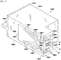
- FIG. 1 shows an inkjet printhead generally designated by reference number 1101.
- the printhead 1101 has a housing 1127 formed of a lid 1161 and a body 1163 assembled together through attachment or connection of a lid bottom surface and a body top surface at interface 1171.
- the shape of the housing varies and depends upon the external device that carries or contains the printhead, the amount of ink to be contained in the printhead and whether the printhead contains one or more varieties of ink.
- the housing or body has at least one compartment in an interior thereof for holding an initial or refillable supply of ink and a structure, such as a foam insert, lung or other, for maintaining appropriate backpressure in the inkjet printhead during use.
- the internal compartment includes three chambers for containing three supplies of ink, especially cyan, magenta and yellow ink.
- the compartment contains black ink, photo-ink and/or plurals of cyan, magenta or yellow ink. It will be appreciated that fluid connections (not shown) may exist to connect the compartment(s) to a remote source of bulk ink.
- a portion 1205 of a tape automated bond (TAB) circuit 1201 adheres to one surface 1181 of the housing while another portion 1211 adheres to another surface 1221. As shown, the two surfaces 1181, 1221 exist perpendicularly to one another about an edge 1231.
- the TAB circuit 1201 has a plurality of input/output (I/O) connectors 1241 fabricated thereon for electrically connecting a heater chip 1251 to an external device, such as a printer, fax machine, copier, photo-printer, plotter, all-in-one, etc., during use.
- I/O input/output
- Pluralities of electrical conductors 1261 exist on the TAB circuit 1201 to electrically connect and short the I/O connectors 1241 to the bond pads 1281 of the heater chip 1251 and various manufacturing techniques are known for facilitating such connections. It will be appreciated that while eight I/O connectors 1241, eight electrical conductors 1261 and eight bond pads 1281 are shown, any number are embraced herein. It is also to be appreciated that such number of connectors, conductors and bond pads may not be equal to one another.
- the heater chip 1251 contains at least one ink via 1321 that fluidly connects to a supply of ink in an interior of the housing.
- the number of ink vias of the heater chip corresponds one-to-one with the number of ink types contained within the housing interior.
- the vias usually reside side-by-side or end-to-end.
- the heater chip 1251 preferably attaches to the housing with any of a variety of adhesives, epoxies, etc. well known in the art.
- the heater chip contains four rows (rows A-row D) of fluid firing elements, especially resistive heating elements, or heaters. For simplicity, dots depict the heaters in the rows and typical printheads contain hundreds of heaters.
- the heaters of the heater chip preferably become formed as a series of thin film layers made via growth, deposition, masking, photolithography and/or etching or other processing steps.
- the heater chip is merely a semiconductor die that contains piezoelectric elements, as the fluid firing elements, for electro-mechanically ejecting ink.
- the term heater chip will encompass both embodiments despite the name "heater” implying an electro-thermal ejection of ink.
- the entirety of the heater chip may be configured as a side-shooter structure instead of the roof-shooter structure shown.
- FIG. 2 shows an external device in the form of an inkjet printer for containing the printhead 1101, generally designated by reference number 1401.
- the printer 1401 includes a carriage 1421 having a plurality of slots 1441 for containing one or more printheads.
- the carriage 1421 is caused to reciprocate (via an output 1591 of a controller 1571) along a shaft 1481 above a print zone 1431 by a motive force supplied to a drive belt 1501 as is well known in the art.
- the reciprocation of the carriage 1421 is performed relative to a print medium, such as a sheet of paper 1521, that is advanced in the printer 1401 along a paper path from an input tray 1541, through the print zone 1431, to an output tray 1561.
- the carriage 1421 reciprocates in the Reciprocating Direction generally perpendicularly to the paper Advance Direction as shown by the arrows.
- Ink drops from the printheads are caused to be ejected from the heater chip 1251 ( FIG. 1 ) at such times pursuant to commands of a printer microprocessor or other controller 1571.
- the timing of the ink drop emissions corresponds to a pattern of pixels of the image being printed. Often times, such patterns are generated in devices electrically connected to the controller (via Ext. input) that are external to the printer such as a computer, a scanner, a camera, a visual display unit, a personal data assistant, or other.
- a control panel 1581 having user selection interface 1601 may also provide input 1621 to the controller 1571 to enable additional printer capabilities and robustness.
- the fluid firing elements (the dots of rows A-D, FIG. 1 ) are uniquely addressed with a small amount of current to rapidly heat a small volume of ink. This causes the ink to vaporize in a local ink chamber and be ejected through the nozzle plate towards the print medium.
- the fire pulse required to emit such ink drop may embody a single or a split firing pulse and is received at the heater chip on an input terminal (e.g., bond pad 1281) from connections between the bond pad 1281, the electrical conductors 1261, the I/O connectors 1241 and controller 1571.
- Internal heater chip wiring conveys the fire pulse from the input terminal to one or many of the fluid firing elements.
- a printhead according to exemplary embodiments of the present invention must be able to accommodate ketone, acetate and alcohol based inks.
- certain materials that are compatible with such inks may be selected for the body and lid of the printhead and internal features and the back pressure system of the printhead may be altered as compared to conventional printheads.
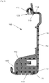
- FIG. 3 is an exploded perspective view and FIGS. 4 and 5 are cross-sectional views of a printhead assembly, generally designated as reference number 1, according to an exemplary embodiment of the present invention.
- the printhead assembly 1 includes an ink cartridge body 10, filter 20, filter cap 30, gasket 40, in reservoir 50, fill ball 60 and lid 70.
- the ink cartridge body 110 includes a datum surface 13.
- the ink cartridge body 10 has a chamber 12 that is sized and configured to receive the ink reservoir 50. Although only one ink reservoir 50 is shown in the figures, it should be appreciated that multiple ink reservoirs may be provided to accommodate one or more color inks.
- the ink reservoir 50 includes an exit port 52 for delivery of the ink, once installed in the chamber 12, and the port 52 can include an interface structure as appropriate, such as a lip or extension.
- the exit port 52 can be sealed using a removable seal, which can be removed at the time of installation.
- a print head chip 11 including a plurality of nozzles for delivery of the ink to the print medium.
- the nozzles are provided on a structure separate from the chip.
- the ink flows from the exit port 52 of the ink reservoir 50 through channels in the lower portion of the body 10.
- the ink then flows within the body 10 to a manifold in the print head chip 11, from which it is drawn to the nozzles for ejection onto the print medium, such as by using heater elements or piezoelectric elements formed in the chip 11.
- the system 1 is moved relative to the print medium, such that the nozzles drop ink at one or more desired locations on the medium.
- the lower portion of the ink cartridge body 10 includes a tower 14.
- the tower 14 may include any appropriate extension, structure, port, or interface for receiving ink for printing.
- the tower 14 of this example includes a raised tubular extension, or standpipe, having one or more openings 15 through which the ink may flow.
- Other tower configurations are also possible as will be readily apparent to one of ordinary skill in the art.
- the filter cap 30 engages the tower 14, and in particular may be welded to an upstanding outer perimeter wall of the tower 14.
- the filter cap 30 includes a conduit or guide component for providing a passage between the ink cartridge body 10 and the ink reservoir 50.
- the filter cap 30 includes an inner passage 32 for providing ink therethrough, the passage 32 being defined by a smaller diameter upper passage portion 34 at the ink reservoir end and a larger diameter lower passage portion 36 at the ink cartridge body end.
- the filter cap 30 may be made of a polyamide, such as, for example, nylon, or other suitable materials that can provide a fluid resistant seal against the tower 14, ink cartridge body 10, and/or ink reservoir 50.
- the upper passage portion 34 of the filter cap 30 engages a corresponding exit port 52 of the ink reservoir 50 to allow ink to flow from the ink reservoir 50 to the passage 32 of the filter cap 30.
- a sealing member is disposed adjacent the filter cap 30 and assists in sealing between the filter cap 30 and the ink reservoir 50.
- the sealing member includes the gasket 40 that engages the upper passage portion 34, so as to create a fluidic seal to control fluid and evaporative losses from the system, and prevent air from entering the system to maintain back pressure.
- the gasket 40 may be made of a suitable elastomer material, or other material with good sealing properties.
- the filter 20 filters contaminants in the ink from reaching the printhead chip.
- the filter 20 can also provide capillary functions to allow ink to pass upon demand to the printhead chip and to prevent air passage into the printhead chip.
- the filter 20 can be made of a metal weave, a polymer weave, or other mesh, screen, or weave materials. For instance, a stainless steel dutch twill or a stainless steel random weave material may be used to form the filter 20.
- the filter 20 may be insert injection molded in the tower 14, or otherwise disposed in the ink cartridge body 10. As another example, the filter 20 may be heat staked to the ink cartridge body 10.
- the material used to form the ink cartridge body 10 and associated lid 70 may be, for example, nylon (e.g., Nylon 6,6, Nylon 6, Nylon 6,12), polyethersulfone, polypropylene, polyethylene, polyoxymethylene or other materials that are compatible with ketone, acetate and alcohol based inks. Since these materials exhibit vapor loss through permeation, a secondary boundary may be provided in the form of the ink reservoir 50.
- the ink reservoir 50 may be made of polypropylene and/or polyethylene based materials so as to create a sufficient permeation barrier.
- the ink reservoir 50 is also provided to serve as a back pressure device since conventional back pressure devices are made of foam or felt materials, which are easily attacked by ketone, acetate and alcohol based inks.
- the ink reservoir 50 provides the primary permeation boundary for the ink cartridge body 10 and when the ink reservoir 50 is attached internally to the ink cartridge body 10 and lid 70, a tortuous vent path is created having a high length to area ratio. This tortuous path allows air to move through it, while maintaining a high humidity environment, which reduces evaporative losses and greatly reduces permeation from the system.
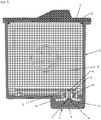
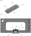
- FIG. 6 is an exploded perspective view of the ink reservoir 50.
- the ink reservoir 50 is made up of a peripheral frame 51, spring 53, side plates 54, and side walls 55.
- the frame 51 is generally rectangular shaped and is open on both sides.
- the frame 51 may be made of a polypropylene and/or polyethylene based material.
- An ink fill hole 56 is disposed at the top of the frame 51.
- the lid includes an opening 72 that corresponds with the ink fill hole 56 of the frame 51, as well as an air vent opening 74 and indent 76 for locking an associated muzzle cap in place (as described in more detail below).
- the fill ball 60 may be disposed within the ink fill hole 56 to allow for passage of ink into the ink reservoir 50 while preventing leakage of ink out of the ink reservoir 50.
- the spring 53 may be made from 316 stainless steel or other compatible material, and is used to deliver force to the side plates 54, to generate a back pressure.
- the side plates 54 may be made of 316 stainless steel or other comparable material, and act as the rigid surface area that generates the back pressure in the system.
- the side plates 54 may be attached to the spring 53 at either end. In an exemplary embodiment, the side plates 54 may be attached to the side walls 55, though they need not be.
- the side walls 55 are made of multi-layer polymeric films that are thermally formed and then welded to the sides of the frame 51 to create the chamber needed to store the ink.
- the polymeric film used to form the side walls 55 may be, for example, thermally formed polypropylene and/or polyethylene film.
- ink is ejected out of the nozzles, causing an increase in negative pressure under the filter 20.
- This negative pressure pulls ink from above the filter 20 and into the tower 14. Since the ink reservoir 50 is in direct fluid connection with the tower 14, the negative back pressure inside the ink reservoir 50 increases as well. The negative back pressure pulls against the side walls 55 and side plates 54, which causes the spring 53 to collapse further.
- the spring 53 is what maintains and dictates the static back pressure in the system.
- a muzzle cap keeps the printhead completely sealed during shipping and maintains the pressure inside the printhead cavity equalized with the surrounding atmosphere upon removal of the muzzle cap to minimize the risk of drooling or air ingestion into the printhead.
- the muzzle cap seals the nozzle plate, covering each and every nozzle, without causing damage to the nozzle plate, and also seals the atmospheric vent in the printhead to prevent air pressure changes from reaching the back pressure device.
- the opening of these seals is done in a particular order in order to prevent problems from occurring.
- the atmospheric vent must be opened first in order to equalize the internal pressure in the printhead prior to the opening of the nozzles.
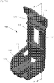
- FIGS. 7A and 7B show perspective views and FIG. 8 is a cross-sectional view of a muzzle cap, generally designed by reference number 100, according to an exemplary embodiment of the present invention.
- the muzzle cap 100 includes a main body 110, vent seal 120, nozzle plate seal 130 and nozzle plate seal retainer 140.
- the main body 110 may be a unitary member including a side wall 112, a top wall 114 and a bottom wall 116.
- the main body 110 is made of a plastic that is compatible with the ketone and acetate based inks that is being jetted, so as to not degrade in the presence of the ink.
- the main body 110 may be made of nylon(e.g., Nylon 6,6, Nylon 6, Nylon 6,12), polyethersulfone, polypropylene, polyethylene, polyoxymethylene or other materials that are compatible with ketone, acetate and alcohol based inks.
- the main body 110 includes guiding and locking elements, such as protrusions 113 and snap-locking element 119. As described in further detail below, these features locate the vent seal 120 and nozzle plate seal 130 relative to the printhead assembly 1 as accurately as possible so as to cover openings in the printhead assembly 1 and lock the muzzle cap 100 in place relative to the printhead assembly 1.
- the main body 110 may also contain datum features 152 that directly address datum features 13 on the printhead in order to minimize tolerance stack-ups.
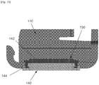
- the main body 110 may include a datum biasing element 154 ( FIG. 19 ) that applies force to push the datum feature 13 of the printhead body 10 into engagement with the datum feature 152 on the main body 110.
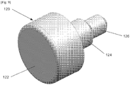
- FIG. 9 is a perspective view of the vent seal 120, which is preferably made of a thermoset elastomer, such as a peroxide cured ethylene propylene diene monomer (EPDM) material, so as to reduce compression set over time and provide maximum resistance to the ketone and acetate solvent inks.
- the vent seal 120 closes the opening in the printhead assembly 1 that is in direct communication with the atmosphere, where the opening otherwise allows air to enter the internals of the printhead assembly 1 during printing as ink is displaced.
- the vent seal 120 is a generally cylindrical element portions of which have different diameters from one another.
- the vent seal 120 includes a sealing surface portion 122 that interfaces with the air vent opening 74 in the lid 70, where the opening has a raised rim around it. This seals the opening with minimal force.
- a compression locking portion 124 which has a smaller diameter than the sealing surface portion 122, compresses into an opening 115 in the top wall 114 of the main body 110 of the muzzle cap 100 so as to create an interference fit between the compression locking portion 124 and the opening 115.
- the assembly lead in portion 126 which has a smaller diameter than the compression locking portion 124, allows the vent seal 120 to be grabbed with a tool to pull the vent seal 120 into place.
- the nozzle plate seal retainer 140 may be molded into the muzzle body 110 so as to reduce tooling and component costs, and eliminate the need to track an additional component. Prior to use of the muzzle cap 100, the nozzle plate seal retainer 140 is twisted out of the muzzle body 110 and pressed into the nozzle plate seal 130.
- FIG. 11 is a perspective view and FIG. 12 is a cross-sectional view of the nozzle plate seal 130.
- the nozzle plate seal 130 is a generally open-bottomed cuboid shaped element including a top portion 131 and a bottom portion 134.
- the nozzle plate seal 130 is preferably made of a thermoset elastomer, such as a peroxide cured ethylene propylene diene monomer (EPDM) material, so as to reduce compression set over time and provide maximum resistance to the ketone and acetate solvent inks.
- the top surface of the top portion 131 of the nozzle plate seal includes an elevated portion that forms a sealing surface 132.
- the sealing surface 132 has a smooth finish that allows good sealing to the nozzles.
- the perimeter of the bottom portion 134 locates the nozzle plate seal 130 in a corresponding opening 117 in the muzzle body 110, and, as described in further detail below, when used in conjunction with the nozzle plate seal retainer 140, centers the nozzle plate seal 130 in the muzzle body 110.
- the bottom surface of the top portion 131 forms a flexing floor 136 that flexes to reduce the force applied to the nozzle plate and to also provide a uniform distribution of force on the nozzle plate to aid in sealing.
- the top portion 131 of the nozzle plate seal 130 extends over the bottom portion 134 so as to form a retaining lip 138 that acts as a stop for the nozzle plate seal 130 once assembled.
- FIG. 13 is a perspective view of the nozzle plate seal retainer 140, which is preferably made of a plastic material, such as nylon.
- the nozzle plate seal retainer 140 includes a top surface having an elevated portion 142. Teeth-like locking projections 144 are arranged around the perimeter of the elevated portion 142.
- the top surface also includes an elevated perimeter forming a rim 146.
- the nozzle plate seal retainer 140 is engaged with the nozzle plate seal 130 by sliding the elevated portion 142 of the nozzle plate seal retainer 140 into the open bottom of the nozzle plate seal 130.
- the locking projections 144 "bite into” the elastomer material of the nozzle plate seal 130 to retain the nozzle plate seal 130 in place, while naturally centering the nozzle plate seal 130 in the muzzle body opening 117.
- FIGS. 16-18 show assembly of the muzzle cap 100 onto the printhead assembly 1.
- the muzzle cap 100 is placed on the printhead assembly 1 in a manner such that the nozzle plate seal 110 engages and seals the nozzle plate before the vent seal 120 engages and seals the air vent opening in the lid 70 of the printhead assembly 1.
- the datums in the printhead are guided by guides 113 and biased to a datum pad in the muzzle body 110 to provide proper alignment to the nozzle plate seal 130.
- the sequence of steps taken to place the muzzle cap 100 on the printhead assembly 1 may include a first step of engaging the bottom portion of the muzzle cap 100 with the bottom portion of the printhead assembly 1, and then sliding the snap locking element 119 onto the lid 70 so that the snap locking element 119 engages with the indent 76, thereby locking the muzzle cap 100 in place relative to the printhead assembly 1.
- Engagement of the snap locking element 119 with the indent 76 in the lid 70 ensures proper placement of the vent seal 120 over the air vent opening 74 and also causes the nozzle plate seal 130 to deflect into tight engagement with the nozzle plate 13, thereby preventing damage to the nozzle plate 13 and maintaining a uniform force across the nozzle plate 13.
- the snap locking element 119 When removing the muzzle cap 100, the snap locking element 119 must first be disengaged from the lid 70. This allows internal air pressure in the printhead to equalize to atmosphere prior to removal of the nozzle plate seal 130, thereby minimizing drooling due to pressure differentials.
Landscapes
- Ink Jet (AREA)
Claims (15)
- Mündungskappe (100) für eine Druckkopfanordnung (1), umfassend:einen Hauptkörper (110), der eine Seitenwand (112), eine Deckwand (114) und eine Bodenwand (116) umfasst,eine Entlüftungsdichtung (120), die innerhalb einer Öffnung (115) in der Deckwand (114) angeordnet ist,dadurch gekennzeichnet ist, dass sie ferner eine Düsenplattendichtung (130) umfasst, die innerhalb einer Öffnung (117) in der Bodenwand (116) angeordnet ist, undeinen Düsenplattendichtungshalter (140), der die Düsenplattendichtung (130) innerhalb der Öffnung (117) in der Bodenwand (116) hält.
- Mündungskappe (100) nach Anspruch 1, wobei mindestens eine/r von dem Hauptkörper (110), der Entlüftungsdichtung (120), der Düsenplattendichtung (130) oder dem Düsenplattendichtungshalter (140) aus Nylon hergestellt ist.
- Mündungskappe (100) nach Anspruch 1, wobei der Hauptkörper (110) Vorsprünge (113) umfasst, die eine Druckkopfanordnung (1) in einen Eingriff mit der Mündungskappe (100) führen.
- Mündungskappe (100) nach Anspruch 1, wobei die Entlüftungsdichtung (120) eine zylindrische Form aufweist.
- Mündungskappe (100) nach Anspruch 1, wobei die Düsenplattendichtung (130) einen Deckenabschnitt (131) und einen Bodenabschnitt (134) umfasst, wobei der Bodenabschnitt (134) eine Öffnung bildet, wobei der Deckenabschnitt (131) einen erhöhten Abschnitt (142) umfasst, der zum Eingriff mit einer Düsenplatte eines Druckkopfs ausgelegt ist.
- Mündungskappe (100) nach Anspruch 5, wobei der Düsenplattendichtungshalter (140) einen erhöhten Abschnitt (142) umfasst, der zum Eingriff mit der Öffnung der Düsenplattendichtung (130) ausgelegt ist, um die Düsenplattendichtung (130) an ihrer Stelle innerhalb der Öffnung in der Bodenwand (116) des Hauptkörpers (110) zu halten.
- Mündungskappe (100) nach Anspruch 6, wobei der Düsenplattendichtungshalter (140) ferner Verriegelungselemente umfasst, die um den Umfang des erhöhten Abschnitts (142) der Düsenplattendichtung (130) angeordnet sind, wobei die Verriegelungselemente zum Eingriff mit dem Bodenabschnitt (134) der Düsenplattendichtung (130) ausgelegt sind.
- Mündungskappe (100) nach Anspruch 1, ferner umfassend einen Vorsprung, der sich von der Deckwand (114) des Hauptkörpers (110) erstreckt, wobei der Vorsprung zum Eingriff mit einer Öffnung in einem Deckel (70) der Druckkopfanordnung (1) derart ausgelegt ist, dass der Vorsprung von der Öffnung in dem Deckel (70) entfernt werden muss, bevor die Mündungskappe (100) von der Druckkopfanordnung (1) entfernt werden kann.
- Kombination, umfassend:
eine Druckkopfanordnung (1), umfassend:einen Tintenkartuschenkörper (10), der eine Kammer (12) definiert, wobei der Tintenkartuschenkörper (10) aus einem Material hergestellt ist, das aus der Gruppe von Materialien ausgewählt ist, bestehend aus: Nylon, Polyethersulfon, Polypropylen, Polyethylen, Polyoxymethylen,einen Tintenbehälter (50), der innerhalb der Kammer (12) des Tintenkartuschenkörpers (10) angeordnet und ausgelegt ist, um Tinte aufzunehmen und zu enthalten,einen Deckel (70), der über der Kammer (12) des Tintenkartuschenkörpers (10) angeordnet ist, wobei der Deckel (70) eine Entlüftung (74) umfasst,einen Druckkopfchip, der auf dem Tintenkartuschenkörper (10) bereitgestellt ist und mit dem Tintenbehälter (50) in Fluidkommunikation steht, um Tinte von dem Tintenbehälter (50) zum Ausstoß der Tinte auf ein Druckmedium aufzunehmen, wobei der Druckkopf eine Düsenplatte umfasst, undeine Mündungskappe (100), umfassend:einen Hauptkörper (110), der eine Seitenwand (112), eine Deckwand (114) und eine Bodenwand (116) umfasst,eine Entlüftungsdichtung (120), die innerhalb einer Öffnung (114) angeordnet und zum Eingriff mit der Entlüftung (74) der Druckkopfanordnung (1) ausgelegt ist,eine Düsenplattendichtung (130), die innerhalb einer Öffnung (117) in der Bodenwand (116) angeordnet und zum Eingriff mit der Düsenplatte des Druckkopfs ausgelegt ist, undeinen Düsenplattendichtungshalter (140), der die Düsenplattendichtung (130) innerhalb der Öffnung (117) in der Bodenwand (116) hält. - Kombination nach Anspruch 9, wobei mindestens eine/r von dem Hauptkörper (110), der Entlüftungsdichtung (120), der Düsenplattendichtung (130) oder dem Düsenplattendichtungshalter (140) aus Nylon hergestellt ist.
- Kombination nach Anspruch 9, wobei der Hauptkörper (110) Vorsprünge (113) umfasst, welche die Druckkopfanordnung (1) in einen Eingriff mit der Mündungskappe (100) führen.
- Kombination nach Anspruch 9, wobei die Entlüftungsdichtung (120) eine zylindrische Form aufweist.
- Kombination nach Anspruch 9, wobei die Düsenplattendichtung (130) einen Deckenabschnitt (131) und einen Bodenabschnitt (134) umfasst, wobei der Bodenabschnitt (134) eine Öffnung bildet, wobei der Deckenabschnitt (131) einen erhöhten Abschnitt (142) umfasst, der zum Eingriff mit der Düsenplatte des Druckkopfs ausgelegt ist.
- Kombination nach Anspruch 13, wobei der Düsenplattendichtungshalter (140) einen erhöhten Abschnitt (142) umfasst, der zum Eingriff mit der Öffnung der Düsenplattendichtung (130) ausgelegt ist, um die Düsenplattendichtung (130) an ihrer Stelle innerhalb der Öffnung in der Bodenwand (116) des Hauptkörpers (110) zu halten.
- Kombination nach Anspruch 14, wobei der Düsenplattendichtungshalter (140) ferner Verriegelungselemente umfasst, die um den Umfang des erhöhten Abschnitts (142) der Düsenplattendichtung (130) angeordnet sind, wobei die Verriegelungselemente zum Eingriff mit dem Bodenabschnitt (134) der Düsenplattendichtung (130) ausgelegt sind.
Applications Claiming Priority (2)
| Application Number | Priority Date | Filing Date | Title |
|---|---|---|---|
| US14/292,319 US9409399B2 (en) | 2014-05-30 | 2014-05-30 | Muzzle for printhead assembly |
| PCT/JP2015/002574 WO2015182087A1 (en) | 2014-05-30 | 2015-05-21 | Muzzle for printhead assembly |
Publications (3)
| Publication Number | Publication Date |
|---|---|
| EP3148810A1 EP3148810A1 (de) | 2017-04-05 |
| EP3148810A4 EP3148810A4 (de) | 2018-03-21 |
| EP3148810B1 true EP3148810B1 (de) | 2019-01-09 |
Family
ID=54698442
Family Applications (1)
| Application Number | Title | Priority Date | Filing Date |
|---|---|---|---|
| EP15799335.3A Not-in-force EP3148810B1 (de) | 2014-05-30 | 2015-05-21 | Mantel für eine druckkopfanordnung |
Country Status (5)
| Country | Link |
|---|---|
| US (2) | US9409399B2 (de) |
| EP (1) | EP3148810B1 (de) |
| JP (1) | JP6593439B2 (de) |
| CN (2) | CN106414082B (de) |
| WO (1) | WO2015182087A1 (de) |
Families Citing this family (15)
| Publication number | Priority date | Publication date | Assignee | Title |
|---|---|---|---|---|
| US9409399B2 (en) * | 2014-05-30 | 2016-08-09 | Funai Electric Co., Ltd | Muzzle for printhead assembly |
| US10207510B2 (en) | 2016-06-15 | 2019-02-19 | Funai Electric Co., Ltd. | Fluidic dispensing device having a guide portion |
| EP3257676B1 (de) * | 2016-06-15 | 2020-03-25 | Funai Electric Co., Ltd. | Fluidabgabevorrichtung mit funktionen zur verringerung von stauzonen |
| US10336081B2 (en) | 2016-06-27 | 2019-07-02 | Funai Electric Co., Ltd. | Method of maintaining a fluidic dispensing device |
| US9878894B1 (en) * | 2016-07-08 | 2018-01-30 | Funai Electric Co., Ltd. | Fluid delivery devices having improved efficiency in delivering fluid with reduced wastage of fluid |
| US9931851B1 (en) | 2016-09-28 | 2018-04-03 | Funai Electric Co., Ltd. | Fluidic dispensing device and stir bar feedback method and use thereof |
| US10105955B2 (en) | 2016-08-17 | 2018-10-23 | Funai Electric Co., Ltd. | Fluidic dispensing device having a moveable stir bar |
| US9908335B2 (en) | 2016-07-21 | 2018-03-06 | Funai Electric Co., Ltd. | Fluidic dispensing device having features to reduce stagnation zones |
| CN107639939B (zh) * | 2016-07-21 | 2020-02-07 | 船井电机株式会社 | 流体分配装置 |
| JP1584444S (de) * | 2017-02-28 | 2019-02-18 | ||
| JP6954058B2 (ja) * | 2017-11-30 | 2021-10-27 | 株式会社リコー | 液体吐出ヘッド保護部材、液体吐出ヘッド及び液体吐出ユニット |
| DE102018111369A1 (de) * | 2018-05-14 | 2019-11-14 | Bowa Bosse + Wagner Ohg | Vorrichtung zur Aufbewahrung einer Patrone für Tintenstrahldrucker sowie Düsen-Dichtungselement zur Verwendung bei einer derartigen Vorrichtung sowie Montageverfahren |
| CN113348087A (zh) * | 2019-01-21 | 2021-09-03 | 麻线解决方案有限公司 | 具有兼容多个墨盒的单个容器的墨水和处理材料填充系统 |
| JP7344930B2 (ja) * | 2021-06-17 | 2023-09-14 | ローランドディー.ジー.株式会社 | キャップおよびそれを備えたインクジェットプリンタ |
| JP1725734S (ja) * | 2021-11-30 | 2022-09-27 | インクカートリッジ用カバー |
Family Cites Families (24)
| Publication number | Priority date | Publication date | Assignee | Title |
|---|---|---|---|---|
| JP3207491B2 (ja) * | 1992-03-24 | 2001-09-10 | キヤノン株式会社 | インクジェットカートリッジの保管方法およびその収納容器 |
| JPH05293970A (ja) * | 1992-04-21 | 1993-11-09 | Dainippon Ink & Chem Inc | インク容器 |
| JPH10193644A (ja) * | 1997-01-14 | 1998-07-28 | Seiko Epson Corp | 保管ケース |
| JP3747134B2 (ja) | 1998-11-04 | 2006-02-22 | キヤノン株式会社 | インクジェット記録ヘッドカートリッジの保管容器 |
| US6155678A (en) | 1999-10-06 | 2000-12-05 | Lexmark International, Inc. | Replaceable ink cartridge for ink jet pen |
| US6935730B2 (en) | 2000-04-03 | 2005-08-30 | Unicorn Image Products Co. Ltd. Of Zhuhai | One-way valve, valve unit assembly, and ink cartridge using the same |
| CN1172803C (zh) * | 2002-03-08 | 2004-10-27 | 珠海天威飞马打印耗材有限公司 | 墨盒 |
| US6588875B1 (en) * | 2001-12-04 | 2003-07-08 | John W. Kleinhammer | Ink jet cartridge printhead seal |
| JP2003246076A (ja) * | 2002-02-22 | 2003-09-02 | Canon Inc | 液体貯蔵容器及びその製造方法 |
| JP2005028779A (ja) * | 2003-07-07 | 2005-02-03 | Canon Inc | インクタンクおよびインクタンクホルダー |
| JP4626264B2 (ja) * | 2004-10-28 | 2011-02-02 | ブラザー工業株式会社 | 記録ヘッドの保管装置および保管方法 |
| US7192129B2 (en) * | 2004-12-20 | 2007-03-20 | Lexmark International, Inc. | Bridging wick and method for an inkjet printhead |
| JP2006192848A (ja) * | 2005-01-17 | 2006-07-27 | Canon Inc | インクジェット記録ヘッドのパッケージ |
| CN2799241Y (zh) * | 2005-06-06 | 2006-07-26 | 硕印科技股份有限公司 | 墨水匣的墨水充填机构 |
| JP2007022035A (ja) * | 2005-07-21 | 2007-02-01 | Canon Inc | 液体収納容器保護キャップおよび液体収納容器 |
| CN2915505Y (zh) * | 2006-06-23 | 2007-06-27 | 珠海天威技术开发有限公司 | 墨盒 |
| CN200963933Y (zh) * | 2006-09-23 | 2007-10-24 | 珠海天威技术开发有限公司 | 密封塞及墨盒 |
| US7735983B2 (en) * | 2007-02-28 | 2010-06-15 | Eastman Kodak Company | Ink jet ink cartridge with vented wick |
| CN201143796Y (zh) * | 2007-12-10 | 2008-11-05 | 珠海纳思达电子科技有限公司 | 一种用于喷墨打印机墨盒的密封件 |
| CN101585263B (zh) * | 2008-05-21 | 2013-05-01 | 金宝电子工业股份有限公司 | 残墨清洁装置 |
| US8272704B2 (en) * | 2008-05-22 | 2012-09-25 | Zipher Limited | Ink containment system and ink level sensing system for an inkjet cartridge |
| JP2010037459A (ja) * | 2008-08-06 | 2010-02-18 | Canon Inc | 水性インク、インクジェット記録方法、インクカートリッジ、記録ユニット、及びインクジェット記録装置 |
| US7871148B2 (en) * | 2009-01-14 | 2011-01-18 | Phoenix Ink Corporation | Universal inkjet cartridge printhead sealing band |
| US9409399B2 (en) * | 2014-05-30 | 2016-08-09 | Funai Electric Co., Ltd | Muzzle for printhead assembly |
-
2014
- 2014-05-30 US US14/292,319 patent/US9409399B2/en active Active
-
2015
- 2015-05-21 CN CN201580028995.5A patent/CN106414082B/zh active Active
- 2015-05-21 EP EP15799335.3A patent/EP3148810B1/de not_active Not-in-force
- 2015-05-21 JP JP2017515289A patent/JP6593439B2/ja active Active
- 2015-05-21 CN CN201811210448.0A patent/CN109591462B/zh active Active
- 2015-05-21 WO PCT/JP2015/002574 patent/WO2015182087A1/en not_active Ceased
-
2016
- 2016-07-13 US US15/209,456 patent/US9849677B2/en active Active
Non-Patent Citations (1)
| Title |
|---|
| None * |
Also Published As
| Publication number | Publication date |
|---|---|
| WO2015182087A1 (en) | 2015-12-03 |
| EP3148810A1 (de) | 2017-04-05 |
| CN109591462A (zh) | 2019-04-09 |
| US20150343784A1 (en) | 2015-12-03 |
| US20160318305A1 (en) | 2016-11-03 |
| US9849677B2 (en) | 2017-12-26 |
| CN109591462B (zh) | 2020-05-19 |
| US9409399B2 (en) | 2016-08-09 |
| EP3148810A4 (de) | 2018-03-21 |
| JP6593439B2 (ja) | 2019-10-23 |
| CN106414082A (zh) | 2017-02-15 |
| CN106414082B (zh) | 2018-11-02 |
| JP2017516693A (ja) | 2017-06-22 |
Similar Documents
| Publication | Publication Date | Title |
|---|---|---|
| EP3148810B1 (de) | Mantel für eine druckkopfanordnung | |
| US9944086B2 (en) | Printhead assembly | |
| CN116423986B (zh) | 液体喷射装置和液体容器 | |
| US9937723B2 (en) | Agitating member for ink cartridge | |
| US9844940B2 (en) | Printhead cartridge with hydrophobic coating | |
| US20130286113A1 (en) | Ink tank seal retainer with symmetric seal force | |
| JP2009226738A (ja) | インクジェットヘッド | |
| CN100418778C (zh) | 流路连接构造单元 | |
| JP5884265B2 (ja) | 液体噴射ヘッド及び液体噴射装置 |
Legal Events
| Date | Code | Title | Description |
|---|---|---|---|
| STAA | Information on the status of an ep patent application or granted ep patent |
Free format text: STATUS: THE INTERNATIONAL PUBLICATION HAS BEEN MADE |
|
| PUAI | Public reference made under article 153(3) epc to a published international application that has entered the european phase |
Free format text: ORIGINAL CODE: 0009012 |
|
| STAA | Information on the status of an ep patent application or granted ep patent |
Free format text: STATUS: REQUEST FOR EXAMINATION WAS MADE |
|
| 17P | Request for examination filed |
Effective date: 20161222 |
|
| AK | Designated contracting states |
Kind code of ref document: A1 Designated state(s): AL AT BE BG CH CY CZ DE DK EE ES FI FR GB GR HR HU IE IS IT LI LT LU LV MC MK MT NL NO PL PT RO RS SE SI SK SM TR |
|
| AX | Request for extension of the european patent |
Extension state: BA ME |
|
| DAV | Request for validation of the european patent (deleted) | ||
| DAX | Request for extension of the european patent (deleted) | ||
| A4 | Supplementary search report drawn up and despatched |
Effective date: 20180215 |
|
| RIC1 | Information provided on ipc code assigned before grant |
Ipc: B41J 2/165 20060101AFI20180210BHEP |
|
| GRAP | Despatch of communication of intention to grant a patent |
Free format text: ORIGINAL CODE: EPIDOSNIGR1 |
|
| STAA | Information on the status of an ep patent application or granted ep patent |
Free format text: STATUS: GRANT OF PATENT IS INTENDED |
|
| INTG | Intention to grant announced |
Effective date: 20180925 |
|
| GRAS | Grant fee paid |
Free format text: ORIGINAL CODE: EPIDOSNIGR3 |
|
| GRAA | (expected) grant |
Free format text: ORIGINAL CODE: 0009210 |
|
| STAA | Information on the status of an ep patent application or granted ep patent |
Free format text: STATUS: THE PATENT HAS BEEN GRANTED |
|
| AK | Designated contracting states |
Kind code of ref document: B1 Designated state(s): AL AT BE BG CH CY CZ DE DK EE ES FI FR GB GR HR HU IE IS IT LI LT LU LV MC MK MT NL NO PL PT RO RS SE SI SK SM TR |
|
| REG | Reference to a national code |
Ref country code: GB Ref legal event code: FG4D |
|
| REG | Reference to a national code |
Ref country code: CH Ref legal event code: EP Ref country code: AT Ref legal event code: REF Ref document number: 1086809 Country of ref document: AT Kind code of ref document: T Effective date: 20190115 |
|
| REG | Reference to a national code |
Ref country code: DE Ref legal event code: R096 Ref document number: 602015023336 Country of ref document: DE |
|
| REG | Reference to a national code |
Ref country code: IE Ref legal event code: FG4D |
|
| REG | Reference to a national code |
Ref country code: NL Ref legal event code: MP Effective date: 20190109 |
|
| REG | Reference to a national code |
Ref country code: LT Ref legal event code: MG4D |
|
| PG25 | Lapsed in a contracting state [announced via postgrant information from national office to epo] |
Ref country code: NL Free format text: LAPSE BECAUSE OF FAILURE TO SUBMIT A TRANSLATION OF THE DESCRIPTION OR TO PAY THE FEE WITHIN THE PRESCRIBED TIME-LIMIT Effective date: 20190109 |
|
| REG | Reference to a national code |
Ref country code: AT Ref legal event code: MK05 Ref document number: 1086809 Country of ref document: AT Kind code of ref document: T Effective date: 20190109 |
|
| PG25 | Lapsed in a contracting state [announced via postgrant information from national office to epo] |
Ref country code: NO Free format text: LAPSE BECAUSE OF FAILURE TO SUBMIT A TRANSLATION OF THE DESCRIPTION OR TO PAY THE FEE WITHIN THE PRESCRIBED TIME-LIMIT Effective date: 20190409 Ref country code: ES Free format text: LAPSE BECAUSE OF FAILURE TO SUBMIT A TRANSLATION OF THE DESCRIPTION OR TO PAY THE FEE WITHIN THE PRESCRIBED TIME-LIMIT Effective date: 20190109 Ref country code: LT Free format text: LAPSE BECAUSE OF FAILURE TO SUBMIT A TRANSLATION OF THE DESCRIPTION OR TO PAY THE FEE WITHIN THE PRESCRIBED TIME-LIMIT Effective date: 20190109 Ref country code: PL Free format text: LAPSE BECAUSE OF FAILURE TO SUBMIT A TRANSLATION OF THE DESCRIPTION OR TO PAY THE FEE WITHIN THE PRESCRIBED TIME-LIMIT Effective date: 20190109 Ref country code: SE Free format text: LAPSE BECAUSE OF FAILURE TO SUBMIT A TRANSLATION OF THE DESCRIPTION OR TO PAY THE FEE WITHIN THE PRESCRIBED TIME-LIMIT Effective date: 20190109 Ref country code: PT Free format text: LAPSE BECAUSE OF FAILURE TO SUBMIT A TRANSLATION OF THE DESCRIPTION OR TO PAY THE FEE WITHIN THE PRESCRIBED TIME-LIMIT Effective date: 20190509 Ref country code: FI Free format text: LAPSE BECAUSE OF FAILURE TO SUBMIT A TRANSLATION OF THE DESCRIPTION OR TO PAY THE FEE WITHIN THE PRESCRIBED TIME-LIMIT Effective date: 20190109 |
|
| PG25 | Lapsed in a contracting state [announced via postgrant information from national office to epo] |
Ref country code: HR Free format text: LAPSE BECAUSE OF FAILURE TO SUBMIT A TRANSLATION OF THE DESCRIPTION OR TO PAY THE FEE WITHIN THE PRESCRIBED TIME-LIMIT Effective date: 20190109 Ref country code: RS Free format text: LAPSE BECAUSE OF FAILURE TO SUBMIT A TRANSLATION OF THE DESCRIPTION OR TO PAY THE FEE WITHIN THE PRESCRIBED TIME-LIMIT Effective date: 20190109 Ref country code: LV Free format text: LAPSE BECAUSE OF FAILURE TO SUBMIT A TRANSLATION OF THE DESCRIPTION OR TO PAY THE FEE WITHIN THE PRESCRIBED TIME-LIMIT Effective date: 20190109 Ref country code: BG Free format text: LAPSE BECAUSE OF FAILURE TO SUBMIT A TRANSLATION OF THE DESCRIPTION OR TO PAY THE FEE WITHIN THE PRESCRIBED TIME-LIMIT Effective date: 20190409 Ref country code: GR Free format text: LAPSE BECAUSE OF FAILURE TO SUBMIT A TRANSLATION OF THE DESCRIPTION OR TO PAY THE FEE WITHIN THE PRESCRIBED TIME-LIMIT Effective date: 20190410 Ref country code: IS Free format text: LAPSE BECAUSE OF FAILURE TO SUBMIT A TRANSLATION OF THE DESCRIPTION OR TO PAY THE FEE WITHIN THE PRESCRIBED TIME-LIMIT Effective date: 20190509 |
|
| REG | Reference to a national code |
Ref country code: DE Ref legal event code: R097 Ref document number: 602015023336 Country of ref document: DE |
|
| PG25 | Lapsed in a contracting state [announced via postgrant information from national office to epo] |
Ref country code: EE Free format text: LAPSE BECAUSE OF FAILURE TO SUBMIT A TRANSLATION OF THE DESCRIPTION OR TO PAY THE FEE WITHIN THE PRESCRIBED TIME-LIMIT Effective date: 20190109 Ref country code: DK Free format text: LAPSE BECAUSE OF FAILURE TO SUBMIT A TRANSLATION OF THE DESCRIPTION OR TO PAY THE FEE WITHIN THE PRESCRIBED TIME-LIMIT Effective date: 20190109 Ref country code: SK Free format text: LAPSE BECAUSE OF FAILURE TO SUBMIT A TRANSLATION OF THE DESCRIPTION OR TO PAY THE FEE WITHIN THE PRESCRIBED TIME-LIMIT Effective date: 20190109 Ref country code: AL Free format text: LAPSE BECAUSE OF FAILURE TO SUBMIT A TRANSLATION OF THE DESCRIPTION OR TO PAY THE FEE WITHIN THE PRESCRIBED TIME-LIMIT Effective date: 20190109 Ref country code: IT Free format text: LAPSE BECAUSE OF FAILURE TO SUBMIT A TRANSLATION OF THE DESCRIPTION OR TO PAY THE FEE WITHIN THE PRESCRIBED TIME-LIMIT Effective date: 20190109 Ref country code: RO Free format text: LAPSE BECAUSE OF FAILURE TO SUBMIT A TRANSLATION OF THE DESCRIPTION OR TO PAY THE FEE WITHIN THE PRESCRIBED TIME-LIMIT Effective date: 20190109 Ref country code: CZ Free format text: LAPSE BECAUSE OF FAILURE TO SUBMIT A TRANSLATION OF THE DESCRIPTION OR TO PAY THE FEE WITHIN THE PRESCRIBED TIME-LIMIT Effective date: 20190109 Ref country code: AT Free format text: LAPSE BECAUSE OF FAILURE TO SUBMIT A TRANSLATION OF THE DESCRIPTION OR TO PAY THE FEE WITHIN THE PRESCRIBED TIME-LIMIT Effective date: 20190109 |
|
| PLBE | No opposition filed within time limit |
Free format text: ORIGINAL CODE: 0009261 |
|
| STAA | Information on the status of an ep patent application or granted ep patent |
Free format text: STATUS: NO OPPOSITION FILED WITHIN TIME LIMIT |
|
| PG25 | Lapsed in a contracting state [announced via postgrant information from national office to epo] |
Ref country code: SM Free format text: LAPSE BECAUSE OF FAILURE TO SUBMIT A TRANSLATION OF THE DESCRIPTION OR TO PAY THE FEE WITHIN THE PRESCRIBED TIME-LIMIT Effective date: 20190109 |
|
| 26N | No opposition filed |
Effective date: 20191010 |
|
| REG | Reference to a national code |
Ref country code: CH Ref legal event code: PL |
|
| GBPC | Gb: european patent ceased through non-payment of renewal fee |
Effective date: 20190521 |
|
| PG25 | Lapsed in a contracting state [announced via postgrant information from national office to epo] |
Ref country code: MC Free format text: LAPSE BECAUSE OF FAILURE TO SUBMIT A TRANSLATION OF THE DESCRIPTION OR TO PAY THE FEE WITHIN THE PRESCRIBED TIME-LIMIT Effective date: 20190109 Ref country code: CH Free format text: LAPSE BECAUSE OF NON-PAYMENT OF DUE FEES Effective date: 20190531 Ref country code: LI Free format text: LAPSE BECAUSE OF NON-PAYMENT OF DUE FEES Effective date: 20190531 |
|
| REG | Reference to a national code |
Ref country code: BE Ref legal event code: MM Effective date: 20190531 |
|
| PG25 | Lapsed in a contracting state [announced via postgrant information from national office to epo] |
Ref country code: LU Free format text: LAPSE BECAUSE OF NON-PAYMENT OF DUE FEES Effective date: 20190521 Ref country code: SI Free format text: LAPSE BECAUSE OF FAILURE TO SUBMIT A TRANSLATION OF THE DESCRIPTION OR TO PAY THE FEE WITHIN THE PRESCRIBED TIME-LIMIT Effective date: 20190109 |
|
| PG25 | Lapsed in a contracting state [announced via postgrant information from national office to epo] |
Ref country code: TR Free format text: LAPSE BECAUSE OF FAILURE TO SUBMIT A TRANSLATION OF THE DESCRIPTION OR TO PAY THE FEE WITHIN THE PRESCRIBED TIME-LIMIT Effective date: 20190109 |
|
| PG25 | Lapsed in a contracting state [announced via postgrant information from national office to epo] |
Ref country code: IE Free format text: LAPSE BECAUSE OF NON-PAYMENT OF DUE FEES Effective date: 20190521 Ref country code: GB Free format text: LAPSE BECAUSE OF NON-PAYMENT OF DUE FEES Effective date: 20190521 |
|
| PG25 | Lapsed in a contracting state [announced via postgrant information from national office to epo] |
Ref country code: BE Free format text: LAPSE BECAUSE OF NON-PAYMENT OF DUE FEES Effective date: 20190531 |
|
| PG25 | Lapsed in a contracting state [announced via postgrant information from national office to epo] |
Ref country code: FR Free format text: LAPSE BECAUSE OF NON-PAYMENT OF DUE FEES Effective date: 20190531 |
|
| PG25 | Lapsed in a contracting state [announced via postgrant information from national office to epo] |
Ref country code: CY Free format text: LAPSE BECAUSE OF FAILURE TO SUBMIT A TRANSLATION OF THE DESCRIPTION OR TO PAY THE FEE WITHIN THE PRESCRIBED TIME-LIMIT Effective date: 20190109 |
|
| PG25 | Lapsed in a contracting state [announced via postgrant information from national office to epo] |
Ref country code: HU Free format text: LAPSE BECAUSE OF FAILURE TO SUBMIT A TRANSLATION OF THE DESCRIPTION OR TO PAY THE FEE WITHIN THE PRESCRIBED TIME-LIMIT; INVALID AB INITIO Effective date: 20150521 Ref country code: MT Free format text: LAPSE BECAUSE OF FAILURE TO SUBMIT A TRANSLATION OF THE DESCRIPTION OR TO PAY THE FEE WITHIN THE PRESCRIBED TIME-LIMIT Effective date: 20190109 |
|
| PG25 | Lapsed in a contracting state [announced via postgrant information from national office to epo] |
Ref country code: MK Free format text: LAPSE BECAUSE OF FAILURE TO SUBMIT A TRANSLATION OF THE DESCRIPTION OR TO PAY THE FEE WITHIN THE PRESCRIBED TIME-LIMIT Effective date: 20190109 |
|
| PGFP | Annual fee paid to national office [announced via postgrant information from national office to epo] |
Ref country code: DE Payment date: 20240328 Year of fee payment: 10 |
|
| REG | Reference to a national code |
Ref country code: DE Ref legal event code: R081 Ref document number: 602015023336 Country of ref document: DE Owner name: BRADY WORLDWIDE, INC., MILWAUKEE, US Free format text: FORMER OWNER: FUNAI ELECTRIC CO., LTD., DAITO-SHI, OSAKA, JP Ref country code: DE Ref legal event code: R082 Ref document number: 602015023336 Country of ref document: DE Representative=s name: BOULT WADE TENNANT LLP, DE |
|
| REG | Reference to a national code |
Ref country code: DE Ref legal event code: R119 Ref document number: 602015023336 Country of ref document: DE |
|
| PG25 | Lapsed in a contracting state [announced via postgrant information from national office to epo] |
Ref country code: DE Free format text: LAPSE BECAUSE OF NON-PAYMENT OF DUE FEES Effective date: 20251202 |