EP3148877B1 - Appareil déclencheur - Google Patents
Appareil déclencheur Download PDFInfo
- Publication number
- EP3148877B1 EP3148877B1 EP15724011.0A EP15724011A EP3148877B1 EP 3148877 B1 EP3148877 B1 EP 3148877B1 EP 15724011 A EP15724011 A EP 15724011A EP 3148877 B1 EP3148877 B1 EP 3148877B1
- Authority
- EP
- European Patent Office
- Prior art keywords
- signals
- force
- control unit
- stick member
- value
- Prior art date
- Legal status (The legal status is an assumption and is not a legal conclusion. Google has not performed a legal analysis and makes no representation as to the accuracy of the status listed.)
- Active
Links
Images

Classifications
-
- G—PHYSICS
- G05—CONTROLLING; REGULATING
- G05D—SYSTEMS FOR CONTROLLING OR REGULATING NON-ELECTRIC VARIABLES
- G05D1/00—Control of position, course, altitude or attitude of land, water, air or space vehicles, e.g. using automatic pilots
- G05D1/0055—Control of position, course, altitude or attitude of land, water, air or space vehicles, e.g. using automatic pilots with safety arrangements
- G05D1/0077—Control of position, course, altitude or attitude of land, water, air or space vehicles, e.g. using automatic pilots with safety arrangements using redundant signals or controls
-
- G—PHYSICS
- G05—CONTROLLING; REGULATING
- G05G—CONTROL DEVICES OR SYSTEMS INSOFAR AS CHARACTERISED BY MECHANICAL FEATURES ONLY
- G05G7/00—Manually-actuated control mechanisms provided with one single controlling member co-operating with one single controlled member; Details thereof
-
- B—PERFORMING OPERATIONS; TRANSPORTING
- B64—AIRCRAFT; AVIATION; COSMONAUTICS
- B64C—AEROPLANES; HELICOPTERS
- B64C13/00—Control systems or transmitting systems for actuating flying-control surfaces, lift-increasing flaps, air brakes, or spoilers
- B64C13/02—Initiating means
- B64C13/04—Initiating means actuated personally
-
- B—PERFORMING OPERATIONS; TRANSPORTING
- B64—AIRCRAFT; AVIATION; COSMONAUTICS
- B64C—AEROPLANES; HELICOPTERS
- B64C13/00—Control systems or transmitting systems for actuating flying-control surfaces, lift-increasing flaps, air brakes, or spoilers
- B64C13/02—Initiating means
- B64C13/04—Initiating means actuated personally
- B64C13/042—Initiating means actuated personally operated by hand
- B64C13/0421—Initiating means actuated personally operated by hand control sticks for primary flight controls
-
- B—PERFORMING OPERATIONS; TRANSPORTING
- B64—AIRCRAFT; AVIATION; COSMONAUTICS
- B64C—AEROPLANES; HELICOPTERS
- B64C13/00—Control systems or transmitting systems for actuating flying-control surfaces, lift-increasing flaps, air brakes, or spoilers
- B64C13/02—Initiating means
- B64C13/04—Initiating means actuated personally
- B64C13/14—Initiating means actuated personally lockable
-
- B—PERFORMING OPERATIONS; TRANSPORTING
- B64—AIRCRAFT; AVIATION; COSMONAUTICS
- B64C—AEROPLANES; HELICOPTERS
- B64C13/00—Control systems or transmitting systems for actuating flying-control surfaces, lift-increasing flaps, air brakes, or spoilers
- B64C13/24—Transmitting means
- B64C13/26—Transmitting means without power amplification or where power amplification is irrelevant
- B64C13/28—Transmitting means without power amplification or where power amplification is irrelevant mechanical
- B64C13/345—Transmitting means without power amplification or where power amplification is irrelevant mechanical with artificial feel
-
- B—PERFORMING OPERATIONS; TRANSPORTING
- B64—AIRCRAFT; AVIATION; COSMONAUTICS
- B64C—AEROPLANES; HELICOPTERS
- B64C13/00—Control systems or transmitting systems for actuating flying-control surfaces, lift-increasing flaps, air brakes, or spoilers
- B64C13/24—Transmitting means
- B64C13/38—Transmitting means with power amplification
- B64C13/40—Transmitting means with power amplification using fluid pressure
- B64C13/46—Transmitting means with power amplification using fluid pressure with artificial feel
-
- B—PERFORMING OPERATIONS; TRANSPORTING
- B64—AIRCRAFT; AVIATION; COSMONAUTICS
- B64C—AEROPLANES; HELICOPTERS
- B64C13/00—Control systems or transmitting systems for actuating flying-control surfaces, lift-increasing flaps, air brakes, or spoilers
- B64C13/24—Transmitting means
- B64C13/38—Transmitting means with power amplification
- B64C13/50—Transmitting means with power amplification using electrical energy
- B64C13/503—Fly-by-Wire
-
- B—PERFORMING OPERATIONS; TRANSPORTING
- B64—AIRCRAFT; AVIATION; COSMONAUTICS
- B64C—AEROPLANES; HELICOPTERS
- B64C13/00—Control systems or transmitting systems for actuating flying-control surfaces, lift-increasing flaps, air brakes, or spoilers
- B64C13/24—Transmitting means
- B64C13/38—Transmitting means with power amplification
- B64C13/50—Transmitting means with power amplification using electrical energy
- B64C13/506—Transmitting means with power amplification using electrical energy overriding of personal controls; with automatic return to inoperative position
-
- B—PERFORMING OPERATIONS; TRANSPORTING
- B64—AIRCRAFT; AVIATION; COSMONAUTICS
- B64C—AEROPLANES; HELICOPTERS
- B64C13/00—Control systems or transmitting systems for actuating flying-control surfaces, lift-increasing flaps, air brakes, or spoilers
- B64C13/24—Transmitting means
- B64C13/38—Transmitting means with power amplification
- B64C13/50—Transmitting means with power amplification using electrical energy
- B64C13/507—Transmitting means with power amplification using electrical energy with artificial feel
-
- G—PHYSICS
- G05—CONTROLLING; REGULATING
- G05G—CONTROL DEVICES OR SYSTEMS INSOFAR AS CHARACTERISED BY MECHANICAL FEATURES ONLY
- G05G1/00—Controlling members, e.g. knobs or handles; Assemblies or arrangements thereof; Indicating position of controlling members
- G05G1/04—Controlling members for hand actuation by pivoting movement, e.g. levers
-
- G—PHYSICS
- G05—CONTROLLING; REGULATING
- G05G—CONTROL DEVICES OR SYSTEMS INSOFAR AS CHARACTERISED BY MECHANICAL FEATURES ONLY
- G05G11/00—Manually-actuated control mechanisms provided with two or more controlling members co-operating with one single controlled member
-
- G—PHYSICS
- G05—CONTROLLING; REGULATING
- G05G—CONTROL DEVICES OR SYSTEMS INSOFAR AS CHARACTERISED BY MECHANICAL FEATURES ONLY
- G05G5/00—Means for preventing, limiting or returning the movements of parts of a control mechanism, e.g. locking controlling member
- G05G5/12—Means for preventing, limiting or returning the movements of parts of a control mechanism, e.g. locking controlling member for holding members in an indefinite number of positions, e.g. by a toothed quadrant
-
- G—PHYSICS
- G05—CONTROLLING; REGULATING
- G05G—CONTROL DEVICES OR SYSTEMS INSOFAR AS CHARACTERISED BY MECHANICAL FEATURES ONLY
- G05G9/00—Manually-actuated control mechanisms provided with one single controlling member co-operating with two or more controlled members, e.g. selectively, simultaneously
-
- G—PHYSICS
- G05—CONTROLLING; REGULATING
- G05G—CONTROL DEVICES OR SYSTEMS INSOFAR AS CHARACTERISED BY MECHANICAL FEATURES ONLY
- G05G9/00—Manually-actuated control mechanisms provided with one single controlling member co-operating with two or more controlled members, e.g. selectively, simultaneously
- G05G9/02—Manually-actuated control mechanisms provided with one single controlling member co-operating with two or more controlled members, e.g. selectively, simultaneously the controlling member being movable in different independent ways, movement in each individual way actuating one controlled member only
- G05G9/04—Manually-actuated control mechanisms provided with one single controlling member co-operating with two or more controlled members, e.g. selectively, simultaneously the controlling member being movable in different independent ways, movement in each individual way actuating one controlled member only in which movement in two or more ways can occur simultaneously
- G05G9/047—Manually-actuated control mechanisms provided with one single controlling member co-operating with two or more controlled members, e.g. selectively, simultaneously the controlling member being movable in different independent ways, movement in each individual way actuating one controlled member only in which movement in two or more ways can occur simultaneously the controlling member being movable by hand about orthogonal axes, e.g. joysticks
-
- G—PHYSICS
- G05—CONTROLLING; REGULATING
- G05G—CONTROL DEVICES OR SYSTEMS INSOFAR AS CHARACTERISED BY MECHANICAL FEATURES ONLY
- G05G9/00—Manually-actuated control mechanisms provided with one single controlling member co-operating with two or more controlled members, e.g. selectively, simultaneously
- G05G9/02—Manually-actuated control mechanisms provided with one single controlling member co-operating with two or more controlled members, e.g. selectively, simultaneously the controlling member being movable in different independent ways, movement in each individual way actuating one controlled member only
- G05G9/04—Manually-actuated control mechanisms provided with one single controlling member co-operating with two or more controlled members, e.g. selectively, simultaneously the controlling member being movable in different independent ways, movement in each individual way actuating one controlled member only in which movement in two or more ways can occur simultaneously
- G05G9/047—Manually-actuated control mechanisms provided with one single controlling member co-operating with two or more controlled members, e.g. selectively, simultaneously the controlling member being movable in different independent ways, movement in each individual way actuating one controlled member only in which movement in two or more ways can occur simultaneously the controlling member being movable by hand about orthogonal axes, e.g. joysticks
- G05G2009/04703—Mounting of controlling member
- G05G2009/04714—Mounting of controlling member with orthogonal axes
- G05G2009/04718—Mounting of controlling member with orthogonal axes with cardan or gimbal type joint
-
- G—PHYSICS
- G05—CONTROLLING; REGULATING
- G05G—CONTROL DEVICES OR SYSTEMS INSOFAR AS CHARACTERISED BY MECHANICAL FEATURES ONLY
- G05G9/00—Manually-actuated control mechanisms provided with one single controlling member co-operating with two or more controlled members, e.g. selectively, simultaneously
- G05G9/02—Manually-actuated control mechanisms provided with one single controlling member co-operating with two or more controlled members, e.g. selectively, simultaneously the controlling member being movable in different independent ways, movement in each individual way actuating one controlled member only
- G05G9/04—Manually-actuated control mechanisms provided with one single controlling member co-operating with two or more controlled members, e.g. selectively, simultaneously the controlling member being movable in different independent ways, movement in each individual way actuating one controlled member only in which movement in two or more ways can occur simultaneously
- G05G9/047—Manually-actuated control mechanisms provided with one single controlling member co-operating with two or more controlled members, e.g. selectively, simultaneously the controlling member being movable in different independent ways, movement in each individual way actuating one controlled member only in which movement in two or more ways can occur simultaneously the controlling member being movable by hand about orthogonal axes, e.g. joysticks
- G05G2009/0474—Manually-actuated control mechanisms provided with one single controlling member co-operating with two or more controlled members, e.g. selectively, simultaneously the controlling member being movable in different independent ways, movement in each individual way actuating one controlled member only in which movement in two or more ways can occur simultaneously the controlling member being movable by hand about orthogonal axes, e.g. joysticks characterised by means converting mechanical movement into electric signals
- G05G2009/04748—Position sensor for rotary movement, e.g. potentiometer
-
- G—PHYSICS
- G05—CONTROLLING; REGULATING
- G05G—CONTROL DEVICES OR SYSTEMS INSOFAR AS CHARACTERISED BY MECHANICAL FEATURES ONLY
- G05G9/00—Manually-actuated control mechanisms provided with one single controlling member co-operating with two or more controlled members, e.g. selectively, simultaneously
- G05G9/02—Manually-actuated control mechanisms provided with one single controlling member co-operating with two or more controlled members, e.g. selectively, simultaneously the controlling member being movable in different independent ways, movement in each individual way actuating one controlled member only
- G05G9/04—Manually-actuated control mechanisms provided with one single controlling member co-operating with two or more controlled members, e.g. selectively, simultaneously the controlling member being movable in different independent ways, movement in each individual way actuating one controlled member only in which movement in two or more ways can occur simultaneously
- G05G9/047—Manually-actuated control mechanisms provided with one single controlling member co-operating with two or more controlled members, e.g. selectively, simultaneously the controlling member being movable in different independent ways, movement in each individual way actuating one controlled member only in which movement in two or more ways can occur simultaneously the controlling member being movable by hand about orthogonal axes, e.g. joysticks
- G05G2009/0474—Manually-actuated control mechanisms provided with one single controlling member co-operating with two or more controlled members, e.g. selectively, simultaneously the controlling member being movable in different independent ways, movement in each individual way actuating one controlled member only in which movement in two or more ways can occur simultaneously the controlling member being movable by hand about orthogonal axes, e.g. joysticks characterised by means converting mechanical movement into electric signals
- G05G2009/04751—Position sensor for linear movement
-
- G—PHYSICS
- G05—CONTROLLING; REGULATING
- G05G—CONTROL DEVICES OR SYSTEMS INSOFAR AS CHARACTERISED BY MECHANICAL FEATURES ONLY
- G05G9/00—Manually-actuated control mechanisms provided with one single controlling member co-operating with two or more controlled members, e.g. selectively, simultaneously
- G05G9/02—Manually-actuated control mechanisms provided with one single controlling member co-operating with two or more controlled members, e.g. selectively, simultaneously the controlling member being movable in different independent ways, movement in each individual way actuating one controlled member only
- G05G9/04—Manually-actuated control mechanisms provided with one single controlling member co-operating with two or more controlled members, e.g. selectively, simultaneously the controlling member being movable in different independent ways, movement in each individual way actuating one controlled member only in which movement in two or more ways can occur simultaneously
- G05G9/047—Manually-actuated control mechanisms provided with one single controlling member co-operating with two or more controlled members, e.g. selectively, simultaneously the controlling member being movable in different independent ways, movement in each individual way actuating one controlled member only in which movement in two or more ways can occur simultaneously the controlling member being movable by hand about orthogonal axes, e.g. joysticks
- G05G2009/0474—Manually-actuated control mechanisms provided with one single controlling member co-operating with two or more controlled members, e.g. selectively, simultaneously the controlling member being movable in different independent ways, movement in each individual way actuating one controlled member only in which movement in two or more ways can occur simultaneously the controlling member being movable by hand about orthogonal axes, e.g. joysticks characterised by means converting mechanical movement into electric signals
- G05G2009/04762—Force transducer, e.g. strain gauge
-
- G—PHYSICS
- G05—CONTROLLING; REGULATING
- G05G—CONTROL DEVICES OR SYSTEMS INSOFAR AS CHARACTERISED BY MECHANICAL FEATURES ONLY
- G05G9/00—Manually-actuated control mechanisms provided with one single controlling member co-operating with two or more controlled members, e.g. selectively, simultaneously
- G05G9/02—Manually-actuated control mechanisms provided with one single controlling member co-operating with two or more controlled members, e.g. selectively, simultaneously the controlling member being movable in different independent ways, movement in each individual way actuating one controlled member only
- G05G9/04—Manually-actuated control mechanisms provided with one single controlling member co-operating with two or more controlled members, e.g. selectively, simultaneously the controlling member being movable in different independent ways, movement in each individual way actuating one controlled member only in which movement in two or more ways can occur simultaneously
- G05G9/047—Manually-actuated control mechanisms provided with one single controlling member co-operating with two or more controlled members, e.g. selectively, simultaneously the controlling member being movable in different independent ways, movement in each individual way actuating one controlled member only in which movement in two or more ways can occur simultaneously the controlling member being movable by hand about orthogonal axes, e.g. joysticks
- G05G2009/04777—Manually-actuated control mechanisms provided with one single controlling member co-operating with two or more controlled members, e.g. selectively, simultaneously the controlling member being movable in different independent ways, movement in each individual way actuating one controlled member only in which movement in two or more ways can occur simultaneously the controlling member being movable by hand about orthogonal axes, e.g. joysticks with additional push or pull action on the handle
-
- G—PHYSICS
- G05—CONTROLLING; REGULATING
- G05G—CONTROL DEVICES OR SYSTEMS INSOFAR AS CHARACTERISED BY MECHANICAL FEATURES ONLY
- G05G2505/00—Means for preventing, limiting or returning the movements of parts of a control mechanism, e.g. locking controlling member
-
- G—PHYSICS
- G05—CONTROLLING; REGULATING
- G05G—CONTROL DEVICES OR SYSTEMS INSOFAR AS CHARACTERISED BY MECHANICAL FEATURES ONLY
- G05G2700/00—Control mechanisms or elements therefor applying a mechanical movement
- G05G2700/02—Means for regulating or adjusting control mechanisms, e.g. devices for automatic adjustment
Definitions
- the actuator may also be operable to be locked in position relative to the housing, thereby locking the stick member into position in response to a signal received from the control unit.
- the inceptor comprises a stick housing 11 and a stick member 12 (or "control stick”, “side stick” or just “stick”), which are arranged such that the stick member 12 is pivotally mounted to the stick housing 11 at pivot point 13.
- the pivot point 13 acts to divide the stick member 12 into a first member section 14, contained within the stick housing 11, and a second member section 15, external to the stick housing 11.
- the stick housing 11 is fixed to a vehicle carrying the passive active stick apparatus 10.
- the pivot point 13 allows the stick member 12 to pivot with respect to the stick housing 11, as indicated by directional arrows 16 and 17.
- the control stick 12 is pivotably mounted about the pivot point 13 such that it may move in at least one of a first direction and second direction, the second direction being at right angles to the first direction.
- the stick member 12 is pivotably mounted relative to the housing 11.
- the first direction may be an "x” direction (i.e. left and right, as shown in Figure 1 ), or may be a "y” direction which is effectively in and out of the page as shown in Figure 1 .
- the control stick may control an aircraft in pitch and roll directions.
- a gaiter 18 can be provided between the second member section 15 and stick housing 11 to inhibit ingress of unwanted foreign material into the stick housing 11.
- a grip (or grip portion) 19 suitable for engagement by an operator of the passive active stick apparatus 10, so that the operator can move the stick member 12 in either direction "x" shown by directional arrow 16, and at right angles to the direction shown (i.e. in the "y" direction).
- a solid mass 20 may be attached to the first member section 14 at an end distal from the pivot point 13.
- the solid mass 20 is arranged to act as a counter balance to movement of the stick member 12 about pivot point 13 under external acceleration forces exerted on the stick member 12 and associated grip 19.
- first link 21 Also attached to the first member section 14, between the solid mass 20 and the pivot point 13, is a first link 21.
- a first end 22 of the first link 21 is pivotally coupled to the first member section 14 and a second end 23 is pivotally coupled to a second link 24.
- the second link 24 is pivotally attached to the first link 21 at a first end 25 and a second end 26 of the second link 24 is fixedly attached to an output drive axle 27 of a position sensor 28 responsive to, and for generating signals indicative of, stick member position.
- the position sensor 28 further comprises a housing 29 which is fixedly attached to the stick housing 11.
- the position sensor 28 may be responsive to signals in the "x” and "y” directions. Additionally, two such position sensors 28 may be provided, one responsive to motion in the "x” direction, the other responsive to motion in the "y” direction.
- connection of the stick member 12 to the position sensor 28 and/or the means by which the stick member 12 is pivotable relative to the housing 11 may have a different configuration.
- the force sensor 32 provided on the stick member 12 responsive to, and for generating signals indicative of, force applied to the stick member 12 by a user.
- the force sensor 32 may be provided under the grip 19, and in one example, may be responsive to forces in the "x" and "y” direction by being sensitive to the stress and/or strain imposed on the stick member 12 material.
- control unit 40 operable to receive the position and force signals from the position sensor 28 and force sensor 32 respectively, via communication lines 34, 36.
- control unit 40 may be a Flight Control Computer.
- control unit 40 outputs signals containing information and data to parts of the vehicle indicated generally at 48, 50, 52 as shown in Figure 2 , and thereby controls the vehicle.
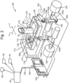
- Figure 2 shows an example of a device of the present disclosure which includes an active inceptor 100.
- the stick member 12 is shown in a truncated form. That is to say the stick member 12 may extend further (i.e. be longer) as shown in Figure 1 .
- the stick member 12 has a base portion 114 and a grip portion 116 which extends from the base portion 114.
- the grip portion 116 is the part which will be handled by an operator, for example a pilot.
- the grip portion 116 may comprise an ergonomic grip to make handling easier, and buttons for the operation of the vehicle.
- the base portion 114 of the stick member 12 comprises a gimbal arrangement having a first base member 118, from which the stick member 12 extends, and a second base member 120.
- the stick member 12 extends from the first base member 118 in only one direction. That is to say, the stick member 12 terminates on the top side of the base member 118, and does not extend beneath the base portion 114.
- the first base member 118 is pivotably coupled to the second base member 120 to permit the stick member 12 and first base member 114 to rotate about a first axis of rotation 122 independently of the second base member 120.
- the second base member 120 is pivotably mounted such that the stick member 12, first base member 118 and second base member 120 are rotatable about a second axis of rotation 124 together.
- a force sensor 32 is provided on the stick member 12.
- the force sensor 32 provided on the stick member 12 is responsive to, and is operable to generate signals indicative of, force applied to the stick 12 by a user.
- a first actuator 126 is coupled to the stick member 12 via the first base member 118.
- a second actuator 128 is coupled to the stick member 12 via the second base member 120.
- the actuators are operable in response to a signal from a control unit 40 to provide positional feedback to the stick member.
- the actuators may be employed to prevent the pilot from moving the stick to an undesirable position, as determined by the control unit 40.
- the first actuator 126 is coupled to the first base member 118 via a first arm 130.
- the arm 130 comprises a link 130a and link 130b which are joined at a pivotable joint 131 such that the arm 130 is articulated.
- the arm 130 is coupled to the first base member 118 by a bearing 132.
- the second actuator 128 is coupled to the second base member 120 by a second arm 144.
- the second arm 144 comprises a link 144a, link 144b and link 144c.
- Links 144a, 144b are joined at a pivotable joint 136a, and links 144b, 144c are joined at a pivotable joint 136b.
- arm 144 comprises a double articulation.
- Link 144c is rigidly attached to the second base member 120.
- actuators 126, 128 each comprise a motor held within a housing, and a shaft extending from the housing.
- the arms 130,144 are fixably connected to their respective shafts.
- the shaft of the first actuator 126 will cause the stick 12 to rotate about the first rotational axis 122 in a first direction, indicated as “x” in Figure 2 .
- rotation of the shaft of the second actuator 128 will cause rotation of the stick member 12 about the second rotational axis 124 in a second direction, shown as “y” in Figure 2 .
- the actuators may be provided as hydraulic devices, or any other appropriate type of actuator.
- the first axis of rotation 122 is at right angles to the second axis of rotation 124. Likewise the first direction “x" and second direction “y" are at right angles to one another.
- At least one of the first or second base members 118,120 is provided with a position sensor 28 (shown in different locations as 28a, 28b) configured to generate a position signal indicative of angle of rotation about their respective rotational axis.
- the position sensors 28 are operable to generate actual stick member position data.
- the first base member 18 may be provided with a first position sensor 28a
- the second base member 120 may be provided with a second position sensor 28b.
- the control unit 40 is configured to receive signals from the force sensor 32 and positional sensors 28a, 28b, for example by communication lines shown as lines 172, 174, 176, respectively.
- a processor 150 may be provided in series with the inceptor 100 and the control unit 40 to process and/or filter the data obtained from the sensors 32, 28 before the signals are passed to the control unit 40 via lines 162,164
- the control unit 40 outputs signals containing various information to parts of the vehicle indicated generally at 48, 50, 52 as shown in Figure 2 , and thereby controls the vehicle.
- control unit 40 is operable to process the signals according to a predetermined relationship to determine a value FD indicative of force applied to the stick member 12 relative to displacement of the stick member 12.
- the control unit 40 is also operable to generate machine control signals as a function of position signals and force signals in dependence upon the value FD for communication to the machine.
- the inceptor and control unit 40 may be provided as separate units and, in practice, may be spaced apart from one another, situated in different zones of the vehicle.
- the control unit 40 may also fulfil other functions as well as processing the signal data as herein described.
- the inceptor 10,100 and control unit 40 thereby combine to provide a flight control system.
- the control unit 40 In generating machine control signals, the control unit 40 varies its sensitivity to force signals and position signals dependent upon the amount of stick member 12 displacement. That is to say, during the step of generating machine control signals, the control unit applies a first variable gain multiplier to force signals, and applies a second variable gain multiplier to position signals, the values of the gain multipliers being varied relative to one another in dependence upon the amount of stick displacement.
Landscapes
- Engineering & Computer Science (AREA)
- Automation & Control Theory (AREA)
- Aviation & Aerospace Engineering (AREA)
- Physics & Mathematics (AREA)
- General Physics & Mathematics (AREA)
- Fluid Mechanics (AREA)
- Mechanical Engineering (AREA)
- Radar, Positioning & Navigation (AREA)
- Remote Sensing (AREA)
- Mechanical Control Devices (AREA)
- Position Input By Displaying (AREA)
- Manipulator (AREA)
Claims (15)
- Appareil d'incepteur actif permettant le fonctionnement d'une machine, l'appareil comprenant :un élément manche (12) ayant une partie de préhension (19), l'élément manche (12) étant monté de mani-re pivotante par rapport à un boîtier (11) ;un capteur de position (28) réagissant à des signaux indiquant une position d'élément manche (12) et générant ceux-ci ;un capteur de force (32) situé sur l'élément manche (12), qui réagit à des signaux indiquant une force appliquée au manche par un utilisateur et génère ceux-ci ; etune unité de commande (40) pouvant fonctionner :pour recevoir les signaux de position et de force en provenance des capteurs de position (28) et de force (32) respectivement ;pour traiter les signaux selon une relation prédéterminée afin de déterminer une valeur FD proportionnelle à une force appliquée par l'utilisateur, telle qu'indiquée par des signaux générés par le capteur de force (32), afin d'obtenir un quelconque déplacement indiqué de l'élément manche (12), tel qu'indiqué par des signaux générés par le capteur de position (28) ; etpour générer des signaux de commande de machine en fonction de signaux de position et de signaux de force conformément à la valeur FD, pour les communiquer à la machine.
- Appareil d'incepteur selon la revendication 1, dans lequel l'unité de commande (40) peut générer des signaux de commande conformément aux signaux de force et aux signaux de position lorsque la valeur FD est inférieure à une limite de tolérance prédéterminée.
- Appareil d'incepteur selon la revendication 1, dans lequel l'unité de commande (40) peut générer des signaux de commande conformément à des signaux de position mais pas à des signaux de force lorsque la valeur FD est inférieure à une limite de tolérance prédéterminée.
- Appareil d'incepteur selon la revendication 2 ou la revendication 3, dans lequel l'unité de commande (40) peut générer des signaux de commande conformément aux signaux de force mais pas aux signaux de position lorsque la valeur FD dépasse la limite de tolérance prédéterminée.
- Appareil d'incepteur selon l'une quelconque des revendications 1 à 4, dans lequel l'élément manche (12) est accouplé à un actionneur pouvant fonctionner en réponse à un signal provenant de l'unité de commande (40).
- Appareil d'incepteur selon la revendication 5, dans lequel, en réponse à un signal reçu en provenance de l'unité de commande (40), l'actionneur peut fonctionner pour pousser l'élément manche (12) vers une position prédéterminée.
- Appareil d'incepteur selon la revendication 5 ou la revendication 6, dans lequel, en réponse à un signal reçu en provenance de l'unité de commande (40), l'actionneur peut être bloqué en position par rapport au boîtier (11), bloquant ainsi l'élément manche (12) en position.
- Appareil d'incepteur selon l'une quelconque des revendications 5 à 7, dans lequel, en réponse à un signal reçu en provenance de l'unité de commande (40), l'actionneur peut fonctionner afin d'être désactivé.
- Appareil d'incepteur selon l'une quelconque des revendications précédentes, dans lequel l'élément manche (12) peut pivoter dans une première direction et une seconde direction, la première direction étant perpendiculaire à la seconde direction.
- Appareil d'incepteur selon l'une quelconque des revendications précédentes, dans lequel, lors de la génération de signaux de commande de machine, l'unité de commande (40) applique un premier multiplicateur de gain variable à des signaux de force et applique un second multiplicateur de gain variable à des signaux de position, les valeurs des multiplicateurs de gain étant modifiées l'une par rapport à l'autre conformément au signal de position.
- Appareil de commande de véhicule comprenant un appareil d'incepteur selon l'une quelconque des revendications précédentes.
- Procédé permettant de commander une machine au moyen d'un appareil d'incepteur actif selon l'une quelconque des revendications 1 à 10, le procédé comprenant les étapes consistant à :recevoir des signaux de position et de force en provenance des capteurs de position (28) et de force (32) respectivement ;déterminer une valeur FD proportionnelle à une force appliquée par l'utilisateur, telle qu'indiquée par les signaux de force reçus, afin d'obtenir un quelconque déplacement indiqué de l'élément manche (12), tel qu'indiqué par les signaux de position reçus ; etgénérer des signaux de commande de machine en fonction de signaux de position et de signaux de force conformément à la valeur FD en vue d'une communication vers la machine.
- Procédé selon la revendication 12, dans lequel, lorsque la valeur FD est inférieure à une limite de tolérance prédéterminée, l'unité de commande (40) génère des signaux de commande conformément aux signaux de force et aux signaux de position.
- Procédé selon la revendication 12, dans lequel, lorsque la valeur FD est inférieure à une limite de tolérance prédéterminée, l'unité de commande (40) génère des signaux de commande conformément aux signaux de position mais pas aux signaux de force.
- Procédé selon la revendication 13 ou la revendication 14, dans lequel, lorsque la valeur FD dépasse la limite de tolérance prédéterminée, l'unité de commande (40) génère des signaux de commande conformément aux signaux de force mais pas aux signaux de position.
Applications Claiming Priority (2)
| Application Number | Priority Date | Filing Date | Title |
|---|---|---|---|
| GBGB1409409.8A GB201409409D0 (en) | 2014-05-28 | 2014-05-28 | Inceptor apparatus |
| PCT/GB2015/051456 WO2015181525A2 (fr) | 2014-05-28 | 2015-05-19 | Appareil déclencheur |
Publications (2)
| Publication Number | Publication Date |
|---|---|
| EP3148877A2 EP3148877A2 (fr) | 2017-04-05 |
| EP3148877B1 true EP3148877B1 (fr) | 2025-03-19 |
Family
ID=51177523
Family Applications (1)
| Application Number | Title | Priority Date | Filing Date |
|---|---|---|---|
| EP15724011.0A Active EP3148877B1 (fr) | 2014-05-28 | 2015-05-19 | Appareil déclencheur |
Country Status (6)
| Country | Link |
|---|---|
| US (1) | US10401855B2 (fr) |
| EP (1) | EP3148877B1 (fr) |
| CN (1) | CN106470898B (fr) |
| ES (1) | ES3028291T3 (fr) |
| GB (2) | GB201409409D0 (fr) |
| WO (1) | WO2015181525A2 (fr) |
Families Citing this family (21)
| Publication number | Priority date | Publication date | Assignee | Title |
|---|---|---|---|---|
| GB201409409D0 (en) | 2014-05-28 | 2014-07-09 | Bae Systems Plc | Inceptor apparatus |
| PL3069990T3 (pl) * | 2015-03-20 | 2017-06-30 | Airbus Helicopters Deutschland GmbH | Urządzenie generujące sztuczne odczucie siły, do systemu sterowania pojazdu, a zwłaszcza statku powietrznego |
| US10118688B2 (en) * | 2015-08-18 | 2018-11-06 | Woodward, Inc. | Inherently balanced control stick |
| GB2549271B (en) * | 2016-04-11 | 2021-07-14 | Bae Systems Plc | An aircraft |
| FR3057243B1 (fr) * | 2016-10-12 | 2018-10-05 | Airbus Helicopters | Organe de commande electrique, aeronef a voilure tournante et procede |
| GB2563243B (en) * | 2017-06-07 | 2020-11-18 | Sony Interactive Entertainment Inc | Input method and apparatus |
| DE202017105886U1 (de) | 2017-09-27 | 2017-11-29 | Spohn & Burkhardt GmbH & Co. KG | Schalteinrichtung |
| CN109866916B (zh) * | 2017-12-01 | 2022-08-02 | 空客直升机 | 电控制构件、旋翼飞行器和方法 |
| US10967953B2 (en) * | 2017-12-11 | 2021-04-06 | The Boeing Company | Combined active stick and control boost actuator system |
| US10831213B2 (en) * | 2018-03-30 | 2020-11-10 | Deere & Company | Targeted loading assistance system |
| US10926869B2 (en) * | 2018-11-29 | 2021-02-23 | The Boeing Company | Jam mitigation in aircraft fly-by-wire systems and related methods |
| WO2020255858A1 (fr) * | 2019-06-19 | 2020-12-24 | アルプスアルパイン株式会社 | Dispositif d'entrée multidirectionnel |
| CN111367354B (zh) * | 2020-03-16 | 2021-05-04 | 四川大学 | 一种海洋平台的操作手柄机构 |
| EP3882134B1 (fr) * | 2020-03-20 | 2024-09-25 | Ratier-Figeac SAS | Système d'initiateur de cockpit |
| CN111552347B (zh) * | 2020-04-27 | 2021-05-28 | 四川大学 | 一种手柄系统 |
| CN111976955B (zh) * | 2020-07-24 | 2023-03-14 | 中国航空工业集团公司西安飞行自动控制研究所 | 民机电传飞控双驾驶杆盘的单侧卡阻故障处理方法和装置 |
| EP3998198B1 (fr) | 2021-02-19 | 2024-07-03 | Lilium eAircraft GmbH | Manche de commande d'aéronef et système de commande de vol d'un aéronef |
| CN114044125B (zh) * | 2021-12-21 | 2024-05-14 | 中国商用飞机有限责任公司 | 飞行器操纵控制系统及控制方法 |
| CN115027662B (zh) * | 2022-07-22 | 2025-01-03 | 中国商用飞机有限责任公司 | 用于减缓飞行器的操纵器件的卡阻的系统和方法 |
| US20240092476A1 (en) * | 2022-09-21 | 2024-03-21 | Gulfstream Aerospace Corporation | Temporary backup control methodology for an inceptor of a vehicle |
| US12515786B2 (en) * | 2023-09-11 | 2026-01-06 | Mu-G Technologies, Llc | Sidestick control apparatus |
Citations (1)
| Publication number | Priority date | Publication date | Assignee | Title |
|---|---|---|---|---|
| WO2004021330A1 (fr) * | 2002-08-29 | 2004-03-11 | Dept. Of Veterans Affairs | Manette a adaptabilite variable faisant appel a des algorithmes de compensation |
Family Cites Families (14)
| Publication number | Priority date | Publication date | Assignee | Title |
|---|---|---|---|---|
| US5209661A (en) * | 1990-10-29 | 1993-05-11 | Systems Control Technology, Inc. | Motor control desired dynamic load of a simulating system and method |
| FR2708112B1 (fr) * | 1993-07-22 | 1995-09-01 | Ratier Figeac Soc | Dispositif de commande à manche de pilotage, notamment mini-manche asservi pour aéronef. |
| US5694014A (en) | 1995-08-22 | 1997-12-02 | Honeywell Inc. | Active hand controller redundancy and architecture |
| US6253136B1 (en) | 1999-03-31 | 2001-06-26 | Caterpillar Inc. | Method and apparatus for a limp home mode |
| US6429849B1 (en) * | 2000-02-29 | 2002-08-06 | Microsoft Corporation | Haptic feedback joystick |
| JP3937914B2 (ja) * | 2002-05-14 | 2007-06-27 | トヨタ自動車株式会社 | 車両操作装置 |
| US8134328B2 (en) * | 2008-04-23 | 2012-03-13 | Honeywell International Inc. | Active pilot inceptor with self warm-up |
| DE102010035825A1 (de) * | 2010-08-30 | 2012-03-01 | Liebherr-Aerospace Lindenberg Gmbh | Steuerorgansystem und Vorrichtung zur Erzeugung eines virtuellen Echtzeitmodells |
| FR2988690B1 (fr) * | 2012-03-27 | 2014-04-25 | Ratier Figeac Soc | Dispositif de pilotage d'un aeronef a capteur d'effort protege |
| GB2509091A (en) * | 2012-12-20 | 2014-06-25 | Bae Systems Plc | Inceptor Apparatus |
| ES2739392T3 (es) * | 2012-12-20 | 2020-01-30 | Bae Systems Plc | Aparato inceptor |
| EP2821328A1 (fr) * | 2013-07-01 | 2015-01-07 | BAE Systems PLC | Unité de contrepoids pour manette |
| GB201409409D0 (en) | 2014-05-28 | 2014-07-09 | Bae Systems Plc | Inceptor apparatus |
| WO2016105650A1 (fr) * | 2014-11-05 | 2016-06-30 | Tzafrir Sheffer | Système de pilote automatique, et composants et procédés associés |
-
2014
- 2014-05-28 GB GBGB1409409.8A patent/GB201409409D0/en not_active Ceased
-
2015
- 2015-05-19 EP EP15724011.0A patent/EP3148877B1/fr active Active
- 2015-05-19 CN CN201580028126.2A patent/CN106470898B/zh active Active
- 2015-05-19 ES ES15724011T patent/ES3028291T3/es active Active
- 2015-05-19 WO PCT/GB2015/051456 patent/WO2015181525A2/fr not_active Ceased
- 2015-05-19 GB GB1508553.3A patent/GB2527924B/en active Active
- 2015-05-19 US US15/313,638 patent/US10401855B2/en active Active
Patent Citations (1)
| Publication number | Priority date | Publication date | Assignee | Title |
|---|---|---|---|---|
| WO2004021330A1 (fr) * | 2002-08-29 | 2004-03-11 | Dept. Of Veterans Affairs | Manette a adaptabilite variable faisant appel a des algorithmes de compensation |
Also Published As
| Publication number | Publication date |
|---|---|
| WO2015181525A3 (fr) | 2016-02-04 |
| CN106470898A (zh) | 2017-03-01 |
| GB201409409D0 (en) | 2014-07-09 |
| EP3148877A2 (fr) | 2017-04-05 |
| GB201508553D0 (en) | 2015-07-01 |
| GB2527924A (en) | 2016-01-06 |
| CN106470898B (zh) | 2020-06-02 |
| GB2527924B (en) | 2018-11-28 |
| US10401855B2 (en) | 2019-09-03 |
| ES3028291T3 (en) | 2025-06-18 |
| US20170212514A1 (en) | 2017-07-27 |
| WO2015181525A2 (fr) | 2015-12-03 |
Similar Documents
| Publication | Publication Date | Title |
|---|---|---|
| EP3148877B1 (fr) | Appareil déclencheur | |
| EP2935000B1 (fr) | Appareil initiateur | |
| EP3659910B1 (fr) | Réduction de l'influence d'un encombrement dans des systèmes de commande de vol électrique d'aéronef et procédés associés | |
| US11919623B2 (en) | Rudder and brake pedal assembly | |
| US8473121B2 (en) | Fly-by-wire control system for an aircraft comprising detection of pilot induced oscillations and a control for such a system | |
| US9073635B2 (en) | Rotorcraft yaw piloting system making use of a member of the human-operated type and of a flight control generator of the objective type | |
| CN114954909A (zh) | 飞行器操纵器装置以及飞行器飞行控制系统 | |
| EP2821341A1 (fr) | Organe de commande et procédé de fonctionnement | |
| EP3016857B1 (fr) | Organe de commande et procédé de fonctionnement | |
| EP1218240B1 (fr) | Systeme de reglage de la sensation d'effort sur le levier a commande de gradient variable | |
| CN105818964B (zh) | 操纵机构的联结方法和联结装置 | |
| CN115027662B (zh) | 用于减缓飞行器的操纵器件的卡阻的系统和方法 | |
| US8219909B2 (en) | Human-machine interface with integrated position sensors and passive haptic feedback devices | |
| GB2509091A (en) | Inceptor Apparatus | |
| CN114044125A (zh) | 飞行器操纵控制系统及控制方法 | |
| US7451664B1 (en) | User interface force sensor system | |
| EP2746153A1 (fr) | Appareil d'organes | |
| GB2516008A (en) | Inceptor and method for operating an inceptor |
Legal Events
| Date | Code | Title | Description |
|---|---|---|---|
| STAA | Information on the status of an ep patent application or granted ep patent |
Free format text: STATUS: THE INTERNATIONAL PUBLICATION HAS BEEN MADE |
|
| PUAI | Public reference made under article 153(3) epc to a published international application that has entered the european phase |
Free format text: ORIGINAL CODE: 0009012 |
|
| STAA | Information on the status of an ep patent application or granted ep patent |
Free format text: STATUS: REQUEST FOR EXAMINATION WAS MADE |
|
| 17P | Request for examination filed |
Effective date: 20161220 |
|
| AK | Designated contracting states |
Kind code of ref document: A2 Designated state(s): AL AT BE BG CH CY CZ DE DK EE ES FI FR GB GR HR HU IE IS IT LI LT LU LV MC MK MT NL NO PL PT RO RS SE SI SK SM TR |
|
| AX | Request for extension of the european patent |
Extension state: BA ME |
|
| DAV | Request for validation of the european patent (deleted) | ||
| DAX | Request for extension of the european patent (deleted) | ||
| STAA | Information on the status of an ep patent application or granted ep patent |
Free format text: STATUS: EXAMINATION IS IN PROGRESS |
|
| 17Q | First examination report despatched |
Effective date: 20210701 |
|
| GRAP | Despatch of communication of intention to grant a patent |
Free format text: ORIGINAL CODE: EPIDOSNIGR1 |
|
| STAA | Information on the status of an ep patent application or granted ep patent |
Free format text: STATUS: GRANT OF PATENT IS INTENDED |
|
| INTG | Intention to grant announced |
Effective date: 20241206 |
|
| GRAS | Grant fee paid |
Free format text: ORIGINAL CODE: EPIDOSNIGR3 |
|
| GRAA | (expected) grant |
Free format text: ORIGINAL CODE: 0009210 |
|
| STAA | Information on the status of an ep patent application or granted ep patent |
Free format text: STATUS: THE PATENT HAS BEEN GRANTED |
|
| AK | Designated contracting states |
Kind code of ref document: B1 Designated state(s): AL AT BE BG CH CY CZ DE DK EE ES FI FR GR HR HU IE IS IT LI LT LU LV MC MK MT NL NO PL PT RO RS SE SI SK SM TR |
|
| RBV | Designated contracting states (corrected) |
Designated state(s): AL AT BE BG CH CY CZ DE DK EE ES FI FR GR HR HU IE IS IT LI LT LU LV MC MK MT NL NO PL PT RO RS SE SI SK SM TR |
|
| REG | Reference to a national code |
Ref country code: CH Ref legal event code: EP |
|
| REG | Reference to a national code |
Ref country code: DE Ref legal event code: R096 Ref document number: 602015091244 Country of ref document: DE |
|
| REG | Reference to a national code |
Ref country code: IE Ref legal event code: FG4D |
|
| REG | Reference to a national code |
Ref country code: ES Ref legal event code: FG2A Ref document number: 3028291 Country of ref document: ES Kind code of ref document: T3 Effective date: 20250618 |
|
| PG25 | Lapsed in a contracting state [announced via postgrant information from national office to epo] |
Ref country code: RS Free format text: LAPSE BECAUSE OF FAILURE TO SUBMIT A TRANSLATION OF THE DESCRIPTION OR TO PAY THE FEE WITHIN THE PRESCRIBED TIME-LIMIT Effective date: 20250619 |
|
| PG25 | Lapsed in a contracting state [announced via postgrant information from national office to epo] |
Ref country code: FI Free format text: LAPSE BECAUSE OF FAILURE TO SUBMIT A TRANSLATION OF THE DESCRIPTION OR TO PAY THE FEE WITHIN THE PRESCRIBED TIME-LIMIT Effective date: 20250319 |
|
| PGFP | Annual fee paid to national office [announced via postgrant information from national office to epo] |
Ref country code: DE Payment date: 20250423 Year of fee payment: 11 |
|
| PGFP | Annual fee paid to national office [announced via postgrant information from national office to epo] |
Ref country code: ES Payment date: 20250602 Year of fee payment: 11 |
|
| REG | Reference to a national code |
Ref country code: LT Ref legal event code: MG9D |
|
| PG25 | Lapsed in a contracting state [announced via postgrant information from national office to epo] |
Ref country code: NO Free format text: LAPSE BECAUSE OF FAILURE TO SUBMIT A TRANSLATION OF THE DESCRIPTION OR TO PAY THE FEE WITHIN THE PRESCRIBED TIME-LIMIT Effective date: 20250619 |
|
| PGFP | Annual fee paid to national office [announced via postgrant information from national office to epo] |
Ref country code: IT Payment date: 20250530 Year of fee payment: 11 |
|
| PG25 | Lapsed in a contracting state [announced via postgrant information from national office to epo] |
Ref country code: HR Free format text: LAPSE BECAUSE OF FAILURE TO SUBMIT A TRANSLATION OF THE DESCRIPTION OR TO PAY THE FEE WITHIN THE PRESCRIBED TIME-LIMIT Effective date: 20250319 |
|
| PG25 | Lapsed in a contracting state [announced via postgrant information from national office to epo] |
Ref country code: LV Free format text: LAPSE BECAUSE OF FAILURE TO SUBMIT A TRANSLATION OF THE DESCRIPTION OR TO PAY THE FEE WITHIN THE PRESCRIBED TIME-LIMIT Effective date: 20250319 |
|
| PGFP | Annual fee paid to national office [announced via postgrant information from national office to epo] |
Ref country code: FR Payment date: 20250423 Year of fee payment: 11 |
|
| PG25 | Lapsed in a contracting state [announced via postgrant information from national office to epo] |
Ref country code: GR Free format text: LAPSE BECAUSE OF FAILURE TO SUBMIT A TRANSLATION OF THE DESCRIPTION OR TO PAY THE FEE WITHIN THE PRESCRIBED TIME-LIMIT Effective date: 20250620 Ref country code: BG Free format text: LAPSE BECAUSE OF FAILURE TO SUBMIT A TRANSLATION OF THE DESCRIPTION OR TO PAY THE FEE WITHIN THE PRESCRIBED TIME-LIMIT Effective date: 20250319 |
|
| PGFP | Annual fee paid to national office [announced via postgrant information from national office to epo] |
Ref country code: TR Payment date: 20250429 Year of fee payment: 11 |
|
| REG | Reference to a national code |
Ref country code: NL Ref legal event code: MP Effective date: 20250319 |
|
| REG | Reference to a national code |
Ref country code: AT Ref legal event code: MK05 Ref document number: 1776776 Country of ref document: AT Kind code of ref document: T Effective date: 20250319 |
|
| PG25 | Lapsed in a contracting state [announced via postgrant information from national office to epo] |
Ref country code: NL Free format text: LAPSE BECAUSE OF FAILURE TO SUBMIT A TRANSLATION OF THE DESCRIPTION OR TO PAY THE FEE WITHIN THE PRESCRIBED TIME-LIMIT Effective date: 20250319 |
|
| PG25 | Lapsed in a contracting state [announced via postgrant information from national office to epo] |
Ref country code: SE Free format text: LAPSE BECAUSE OF FAILURE TO SUBMIT A TRANSLATION OF THE DESCRIPTION OR TO PAY THE FEE WITHIN THE PRESCRIBED TIME-LIMIT Effective date: 20250319 |
|
| PG25 | Lapsed in a contracting state [announced via postgrant information from national office to epo] |
Ref country code: SM Free format text: LAPSE BECAUSE OF FAILURE TO SUBMIT A TRANSLATION OF THE DESCRIPTION OR TO PAY THE FEE WITHIN THE PRESCRIBED TIME-LIMIT Effective date: 20250319 |
|
| PG25 | Lapsed in a contracting state [announced via postgrant information from national office to epo] |
Ref country code: PT Free format text: LAPSE BECAUSE OF FAILURE TO SUBMIT A TRANSLATION OF THE DESCRIPTION OR TO PAY THE FEE WITHIN THE PRESCRIBED TIME-LIMIT Effective date: 20250721 |
|
| PG25 | Lapsed in a contracting state [announced via postgrant information from national office to epo] |
Ref country code: PL Free format text: LAPSE BECAUSE OF FAILURE TO SUBMIT A TRANSLATION OF THE DESCRIPTION OR TO PAY THE FEE WITHIN THE PRESCRIBED TIME-LIMIT Effective date: 20250319 |
|
| PG25 | Lapsed in a contracting state [announced via postgrant information from national office to epo] |
Ref country code: AT Free format text: LAPSE BECAUSE OF FAILURE TO SUBMIT A TRANSLATION OF THE DESCRIPTION OR TO PAY THE FEE WITHIN THE PRESCRIBED TIME-LIMIT Effective date: 20250319 |
|
| PG25 | Lapsed in a contracting state [announced via postgrant information from national office to epo] |
Ref country code: EE Free format text: LAPSE BECAUSE OF FAILURE TO SUBMIT A TRANSLATION OF THE DESCRIPTION OR TO PAY THE FEE WITHIN THE PRESCRIBED TIME-LIMIT Effective date: 20250319 Ref country code: CZ Free format text: LAPSE BECAUSE OF FAILURE TO SUBMIT A TRANSLATION OF THE DESCRIPTION OR TO PAY THE FEE WITHIN THE PRESCRIBED TIME-LIMIT Effective date: 20250319 |
|
| PG25 | Lapsed in a contracting state [announced via postgrant information from national office to epo] |
Ref country code: RO Free format text: LAPSE BECAUSE OF FAILURE TO SUBMIT A TRANSLATION OF THE DESCRIPTION OR TO PAY THE FEE WITHIN THE PRESCRIBED TIME-LIMIT Effective date: 20250319 |
|
| PG25 | Lapsed in a contracting state [announced via postgrant information from national office to epo] |
Ref country code: SK Free format text: LAPSE BECAUSE OF FAILURE TO SUBMIT A TRANSLATION OF THE DESCRIPTION OR TO PAY THE FEE WITHIN THE PRESCRIBED TIME-LIMIT Effective date: 20250319 |
|
| PG25 | Lapsed in a contracting state [announced via postgrant information from national office to epo] |
Ref country code: IS Free format text: LAPSE BECAUSE OF FAILURE TO SUBMIT A TRANSLATION OF THE DESCRIPTION OR TO PAY THE FEE WITHIN THE PRESCRIBED TIME-LIMIT Effective date: 20250719 |
|
| REG | Reference to a national code |
Ref country code: DE Ref legal event code: R097 Ref document number: 602015091244 Country of ref document: DE |
|
| REG | Reference to a national code |
Ref country code: CH Ref legal event code: H13 Free format text: ST27 STATUS EVENT CODE: U-0-0-H10-H13 (AS PROVIDED BY THE NATIONAL OFFICE) Effective date: 20251223 |
|
| PG25 | Lapsed in a contracting state [announced via postgrant information from national office to epo] |
Ref country code: DK Free format text: LAPSE BECAUSE OF FAILURE TO SUBMIT A TRANSLATION OF THE DESCRIPTION OR TO PAY THE FEE WITHIN THE PRESCRIBED TIME-LIMIT Effective date: 20250319 |
|
| PG25 | Lapsed in a contracting state [announced via postgrant information from national office to epo] |
Ref country code: LU Free format text: LAPSE BECAUSE OF NON-PAYMENT OF DUE FEES Effective date: 20250519 |
|
| PG25 | Lapsed in a contracting state [announced via postgrant information from national office to epo] |
Ref country code: CH Free format text: LAPSE BECAUSE OF NON-PAYMENT OF DUE FEES Effective date: 20250531 |
|
| PLBE | No opposition filed within time limit |
Free format text: ORIGINAL CODE: 0009261 |
|
| STAA | Information on the status of an ep patent application or granted ep patent |
Free format text: STATUS: NO OPPOSITION FILED WITHIN TIME LIMIT |
|
| REG | Reference to a national code |
Ref country code: CH Ref legal event code: L10 Free format text: ST27 STATUS EVENT CODE: U-0-0-L10-L00 (AS PROVIDED BY THE NATIONAL OFFICE) Effective date: 20260128 |
|
| REG | Reference to a national code |
Ref country code: BE Ref legal event code: MM Effective date: 20250531 |
|
| PG25 | Lapsed in a contracting state [announced via postgrant information from national office to epo] |
Ref country code: MC Free format text: LAPSE BECAUSE OF FAILURE TO SUBMIT A TRANSLATION OF THE DESCRIPTION OR TO PAY THE FEE WITHIN THE PRESCRIBED TIME-LIMIT Effective date: 20250319 |
|
| 26N | No opposition filed |
Effective date: 20251222 |
|
| PG25 | Lapsed in a contracting state [announced via postgrant information from national office to epo] |
Ref country code: IE Free format text: LAPSE BECAUSE OF NON-PAYMENT OF DUE FEES Effective date: 20250519 |
|
| PG25 | Lapsed in a contracting state [announced via postgrant information from national office to epo] |
Ref country code: BE Free format text: LAPSE BECAUSE OF NON-PAYMENT OF DUE FEES Effective date: 20250531 |