EP3148880B1 - Konvertierbare abgasanlage für drehflügler - Google Patents
Konvertierbare abgasanlage für drehflügler Download PDFInfo
- Publication number
- EP3148880B1 EP3148880B1 EP15799545.7A EP15799545A EP3148880B1 EP 3148880 B1 EP3148880 B1 EP 3148880B1 EP 15799545 A EP15799545 A EP 15799545A EP 3148880 B1 EP3148880 B1 EP 3148880B1
- Authority
- EP
- European Patent Office
- Prior art keywords
- door
- aircraft
- diffuser
- chimney
- exhaust flow
- Prior art date
- Legal status (The legal status is an assumption and is not a legal conclusion. Google has not performed a legal analysis and makes no representation as to the accuracy of the status listed.)
- Not-in-force
Links
- 230000007246 mechanism Effects 0.000 claims description 10
- 238000009413 insulation Methods 0.000 claims description 6
- 239000011888 foil Substances 0.000 claims description 3
- 239000012720 thermal barrier coating Substances 0.000 claims description 3
- 239000003570 air Substances 0.000 description 9
- 230000001629 suppression Effects 0.000 description 6
- 230000000903 blocking effect Effects 0.000 description 3
- 239000012080 ambient air Substances 0.000 description 2
- 230000000694 effects Effects 0.000 description 2
- 238000011084 recovery Methods 0.000 description 2
- 230000009471 action Effects 0.000 description 1
- 230000004075 alteration Effects 0.000 description 1
- 230000015556 catabolic process Effects 0.000 description 1
- 238000006731 degradation reaction Methods 0.000 description 1
- 230000001419 dependent effect Effects 0.000 description 1
- 238000005516 engineering process Methods 0.000 description 1
- 238000002347 injection Methods 0.000 description 1
- 239000007924 injection Substances 0.000 description 1
- 239000012774 insulation material Substances 0.000 description 1
- 239000000203 mixture Substances 0.000 description 1
- 230000005855 radiation Effects 0.000 description 1
- 238000007789 sealing Methods 0.000 description 1
- 239000000243 solution Substances 0.000 description 1
- 238000006467 substitution reaction Methods 0.000 description 1
Images



Classifications
-
- B—PERFORMING OPERATIONS; TRANSPORTING
- B64—AIRCRAFT; AVIATION; COSMONAUTICS
- B64D—EQUIPMENT FOR FITTING IN OR TO AIRCRAFT; FLIGHT SUITS; PARACHUTES; ARRANGEMENT OR MOUNTING OF POWER PLANTS OR PROPULSION TRANSMISSIONS IN AIRCRAFT
- B64D33/00—Arrangement in aircraft of power plant parts or auxiliaries not otherwise provided for
- B64D33/04—Arrangement in aircraft of power plant parts or auxiliaries not otherwise provided for of exhaust outlets or jet pipes
-
- B—PERFORMING OPERATIONS; TRANSPORTING
- B64—AIRCRAFT; AVIATION; COSMONAUTICS
- B64C—AEROPLANES; HELICOPTERS
- B64C27/00—Rotorcraft; Rotors peculiar thereto
- B64C27/04—Helicopters
-
- F—MECHANICAL ENGINEERING; LIGHTING; HEATING; WEAPONS; BLASTING
- F02—COMBUSTION ENGINES; HOT-GAS OR COMBUSTION-PRODUCT ENGINE PLANTS
- F02K—JET-PROPULSION PLANTS
- F02K1/00—Plants characterised by the form or arrangement of the jet pipe or nozzle; Jet pipes or nozzles peculiar thereto
- F02K1/002—Plants characterised by the form or arrangement of the jet pipe or nozzle; Jet pipes or nozzles peculiar thereto with means to modify the direction of thrust vector
-
- F—MECHANICAL ENGINEERING; LIGHTING; HEATING; WEAPONS; BLASTING
- F05—INDEXING SCHEMES RELATING TO ENGINES OR PUMPS IN VARIOUS SUBCLASSES OF CLASSES F01-F04
- F05D—INDEXING SCHEME FOR ASPECTS RELATING TO NON-POSITIVE-DISPLACEMENT MACHINES OR ENGINES, GAS-TURBINES OR JET-PROPULSION PLANTS
- F05D2220/00—Application
- F05D2220/30—Application in turbines
- F05D2220/32—Application in turbines in gas turbines
- F05D2220/329—Application in turbines in gas turbines in helicopters
-
- Y—GENERAL TAGGING OF NEW TECHNOLOGICAL DEVELOPMENTS; GENERAL TAGGING OF CROSS-SECTIONAL TECHNOLOGIES SPANNING OVER SEVERAL SECTIONS OF THE IPC; TECHNICAL SUBJECTS COVERED BY FORMER USPC CROSS-REFERENCE ART COLLECTIONS [XRACs] AND DIGESTS
- Y02—TECHNOLOGIES OR APPLICATIONS FOR MITIGATION OR ADAPTATION AGAINST CLIMATE CHANGE
- Y02T—CLIMATE CHANGE MITIGATION TECHNOLOGIES RELATED TO TRANSPORTATION
- Y02T50/00—Aeronautics or air transport
- Y02T50/60—Efficient propulsion technologies, e.g. for aircraft
Definitions
- the subject matter disclosed herein generally relates to engine systems for powering rotary winged aircraft. More specifically, the subject disclosure relates to exhaust systems for engines of rotary winged aircraft.
- Typical rotary wing aircraft such as helicopters, have one or more engines located at the airframe. These engines are connected to a rotor system, often via a gearbox. The engine produces exhaust, which is expelled from the aircraft via an exhaust duct.
- infrared emissions from the engine be reduced to a practical minimum to avoid acquisition and tracking by heat seeking, hostile forces, or to permit effective countermeasures such as evasive action to be taken against such forces.
- exhaust passageways are typically oriented to allow direct line of sight into the engine core.
- infrared suppression is typically achieved by directing the exhaust upwardly out of the airframe, via a duct with a bend in the duct to transfer the exhaust from a horizontal flow to a vertical flow.
- US 5,699,966 discloses an exhaust nozzle of a gas turbine engine effective for reducing the emission of infrared radiation and providing an extensive maneuvering capability.
- Its nozzle preferably is of the two-dimensional type and includes an exhaust cowl with a generally rectangular cross-sectional exhaust opening and a plug within the downstream end of the cowl.
- Its plug which is preferably wedge-shaped, is pivotable about a transverse axis running through the aft portion of the plug by an appropriate means, for example, a cam or a screw jack mechanism.
- Its nozzle can also include blocker doors and louvers for providing thrust reversal.
- EP 0 406 155 A1 discloses an IR suppressor produces a thin "ribbon" exhaust plume using a tapered exhaust manifold which has a plurality of discrete exhaust nozzles that are longitudinally aligned with the exhaust manifold.
- the nozzles extend within but are spaced apart from mixing ducts which are open to the ambient air at both ends.
- the mixing ducts mix ambient air with the exhaust plume.
- the IR suppressor is rotatable so that the exhaust can be directed substantially parallel to the helicopter blades when the blades are not turning to protect them from exhaust heat.
- US 4,662,174 discloses an assembly having a collector nozzle which is fixed to a turbine engine and which is elbowed laterally towards the exterior and which debouches into injection nozzles which are also elbowed and which open into a mixer masked laterally by a fairing, of which a shaped forward section defines, with an internal shaped screen and a central plug, a semi dynamic principal air inlet. Its aspirated air dilutes the gas in the mixer which is terminated by an elbow directed upwardly and which can pivot about a transverse axis. In the position of maximum deviation upwardly this elbow masks the hot parts of the assembly from the rear. Its assembly is particularly useful for equipping helicopters with lateral exhaust gas turbine engines, and it can be original equipment or retrofitted. Its assembly serves to reduce the infra red emission from the helicopter, to defeat infra red homing missiles.
- US 2003/0192737 A1 discloses a sound attenuating duct unit suitable for connection to an outlet of a gas turbine and an improved heat recovery apparatus for use with such a turbine are disclosed.
- the former unit includes a duct housing having exterior sides, an air inlet at one end and first and second air outlets. Interior walls define a main airflow passageway extending from the air inlet to both of the outlets. Sound absorbing and heat insulation material is arranged between these walls and the exterior sides. Sound attenuating members are mounted in the passageway and a diverter damper is mounted in the housing and is able to direct air flow to either one of the air outlets. The sound attenuating members are mounted between the diverter damper and the air inlet.
- the heat recovery apparatus includes a series of aerodynamic diffusers mounted in a housing adjacent an air flow inlet connectable to the gas turbine.
- Embodiments of the invention may solve one or more of the problems of the art, with the solutions set forth in the independent claim and refinements as recited in the dependent claims.
- an exhaust system of a rotary wing aircraft includes a diffuser located at an airframe of the rotary wing aircraft and operably connected to an engine of the rotary wing aircraft, and a chimney extending upwardly from a diffuser wall.
- a door is movably positioned at the diffuser to selectively direct an engine exhaust flow rearwardly through the diffuser to a diffuser exit or upwardly through the chimney to a chimney exit.
- the door is pivotably secured at the diffuser to rotate about a door axis.
- a piston actuator is operably connected to the door to drive rotation of the door about the door axis.
- a torsional motor is operably connected to the door to drive rotation of the door about the door axis.
- the torsional motor is located at the door axis.
- an insulation layer is applied to at least one surface of the door.
- the insulation layer is an infrared suppressing foil or a thermal barrier coating.
- a locking mechanism is utilized to secure the door in a selected position.
- the rotary wing aircraft includes an airframe, a rotor system positioned at the airframe and rotatable about a rotor axis, and an engine operably connected to the rotor system to drive rotation of the rotor system.
- FIG. 1 Shown in FIG. 1 is a schematic view of an embodiment of a rotary wing aircraft, in this embodiment a helicopter 10.
- the helicopter 10 includes an airframe 12 with an extending tail 14.
- a main rotor assembly 18 is located at the airframe 12 and rotates about a main rotor axis 20.
- the main rotor assembly 18 is driven by a power source, for example, an engine 24 via a gearbox 26 about the main rotor axis 20.
- the rotor assembly 18 includes a plurality of rotor blades 28 secured to a rotor hub 30, with a main rotor shaft 32 connected to the rotor hub 30 and to the gearbox 26 to transfer rotational energy from the gearbox 26 to the main rotor assembly 18.
- the helicopter 10 further includes a tail rotor 16 located at the extending tail 14 to provide yaw control for the helicopter 10.
- the tail rotor 16 is connected to and driven by the engine 24 via the gearbox 26. While shown as a single rotor, it is understood that aspects of the inventions can be used in coaxial rotorcraft, tilt rotor and tilt wing aircraft, and other rotary winged aircraft. Further, while one engine 24 is shown in FIG. 1 , it is to be appreciated that some embodiments may include two or more engines 24.
- the helicopter 10 includes an exhaust system 34 to direct an exhaust flow 36 from the engine 24 and expel the exhaust flow 36 from the helicopter 10.
- the exhaust flow 36 is high temperature and may produce an infrared signature that may allow for acquisition and tracking by heat seeking, hostile forces if line of sight to the exhaust flow 36 is achieved by the hostile forces.
- the exhaust system 34 includes suppression mechanisms that may be activated when desired, and also deactivated so that performance degradation due to the activated suppressor only occurs when the suppression technology is needed, for example, when the helicopter 10 is operating in a hostile zone or hostile airspace.
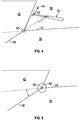
- the exhaust system 34 includes a diffuser 38 to direct the exhaust flow 36 rearwardly to a diffuser exit 40 and a chimney 42 extending upwardly from a diffuser wall 44 to direct exhaust flow 36 upwardly to a chimney exit 46.
- the exhaust system 34 further includes a movable door 48 located in the diffuser 38 to selectively block the exhaust flow 36 from one of the diffuser 38 and the chimney 42 and directing the exhaust flow 36 to the other of the diffuser 38 and the chimney 42.
- the door 48 is moved to a first position preventing the exhaust flow 36 from reaching the diffuser exit 40. Instead, the door 48 directs the exhaust flow 36 through the chimney 42 and out of the chimney exit 46.
- an insulation layer 50 is applied to a surface, for example rearward surface 52, of the door 48.
- the insulation layer 50 is an infrared suppressing foil or a thermal barrier coating.
- the door 48 when suppression of the infrared signature is not needed or desired, the door 48 is moved to a second position blocking a chimney entrance 54, thus directing the exhaust flow 36 down a length of the diffuser 38 and through the diffuser exit 40. Directing the exhaust flow 36 down the diffuser 38 rather than up through the chimney 42 reduces performance losses associated with the suppression system when the suppression is not desired.
- the door 48 is actuated via pilot command. Actuation of the door 48 between the first and second positions may be accomplished in one of several ways, examples of which will be described in the following.
- the door 48 is pivotably located at the diffuser wall 44 so as to rotate about door axis 56.
- the door 48 extends through the diffuser wall 44 to an exterior 58 of the diffuser 38 where the door 48 is operably connected to a piston actuator 60 fixed to the airframe 12.
- the door 48 is connected to the piston actuator via a pin 62 and slide arrangement 64.
- extension of the piston actuator 60 results in the movement of the door 48 across the diffuser 38 to the first position to direct the exhaust flow 36 through the chimney 42
- retraction of the piston actuator 60 results in the movement of the door 48 across the chimney 42 to the second position to direct the exhaust flow 36 through the diffuser 38.
- one or more torsional motors 66 may be connected to the door 48 at the door axis 56 to effect rotation of the door 48.
- the exhaust system 34 includes a locking mechanism 68 to lock the door 48 into the second position blocking the chimney 42.
- a locking actuator 70 is fixed to the airframe 12 and attached to a wedge clamp 72. When the locking actuator 70 is actuated, the wedge clamp 72 is extended beneath the door 48 securing the door 48 in the second position across the chimney 42. Further, a door seal 74 may be positioned between the door 48 and the chimney 42. The door seal 74 is compressed when the door 48 is moved to the second position thus sealing between the door 48 and the chimney 42. While the locking mechanism 68 in the present embodiment is positioned to lock the door 48 in the second position, in other embodiments additional or alternative locking mechanisms may be utilized to lock the door 48 in the first position, blocking the diffuser 38.
Landscapes
- Engineering & Computer Science (AREA)
- Mechanical Engineering (AREA)
- Aviation & Aerospace Engineering (AREA)
- Chemical & Material Sciences (AREA)
- Combustion & Propulsion (AREA)
- General Engineering & Computer Science (AREA)
- Cooling, Air Intake And Gas Exhaust, And Fuel Tank Arrangements In Propulsion Units (AREA)
- Aiming, Guidance, Guns With A Light Source, Armor, Camouflage, And Targets (AREA)
- Exhaust Silencers (AREA)
Claims (10)
- Drehflügler (10), umfassend:ein Flugwerk (12);eine Rotoranlage (18), die am Flugwerk (12) angeordnet ist und um eine Rotorachse (20) drehbar ist;ein Triebwerk (24), das in Wirkverbindung mit der Rotoranlage (18) steht, um die Drehung der Rotoranlage (18) anzutreiben; undeine Abgasanlage (34), die einen Diffusor (38) umfasst, der am Flugwerk (12) angeordnet ist und in Wirkverbindung mit dem Triebwerk (24) steht, um eine Triebwerksabgasströmung (36) nach hinten zu einem Diffusorauslass (40) zu leiten;dadurch gekennzeichnet, dass die Abgasanlage (34) weiter Folgendes umfasst:einen Abzug (42), der sich von einem Abzugseinlass (54) in einer Diffusorwand (44) aus erstreckt, um eine Triebwerksabgasströmung (36) zu einem Abzugsauslass (46) zu leiten; undeine Klappe (48), die im Diffusor (38) zwischen einer ersten Position, in der die Klappe (48) verhindert, dass die Triebwerksabgasströmung (36) zum Diffusorauslass (40) gelangt und stattdessen die Triebwerksabgasströmung (36) durch den Abzug (42) und aus dem Abzugsauslass (46) heraus leitet, und einer zweiten Position, in der die Klappe (48) den Abzugseinlass (54) versperrt und so die Triebwerksabgasströmung (36) entlang des Diffusors (38) und durch den Diffusorauslass (40) leitet, beweglich angeordnet ist.
- Luftfahrzeug (10) nach Anspruch 1, wobei die Klappe (48) gelenkig an der Diffusorwand (44) fixiert ist, um sich um eine Klappenachse (56) zu drehen.
- Luftfahrzeug (10) nach Anspruch 1 oder 2, weiter umfassend einen Kolbenstellantrieb (60), der in Wirkverbindung mit der Klappe (48) steht, um die Drehung der Klappe (48) um die Klappenachse (56) anzutreiben.
- Luftfahrzeug (10) nach einem der Ansprüche 1 - 3, weiter umfassend einen Drehmotor (66), der in Wirkverbindung mit der Klappe (48) steht, um die Drehung der Klappe (48) um die Klappenachse (56) anzutreiben.
- Luftfahrzeug (10) nach Anspruch 4, wobei der Drehmotor (66) an der Klappenachse (56) angeordnet ist.
- Luftfahrzeug (10) nach einem der Ansprüche 1 - 5, wobei eine Isolierschicht (50) an mindestens einer Fläche der Klappe (48) aufgebracht ist.
- Luftfahrzeug (10) nach Anspruch 6, wobei die Isolierschicht (50) eine die Infrarotstrahlung abschirmende Folie oder eine Wärmedämmbeschichtung ist.
- Luftfahrzeug (10) nach einem der Ansprüche 1 - 7, weiter umfassend einen Verriegelungsmechanismus (68), um die Klappe (48) in einer ausgewählten Position zu sichern.
- Luftfahrzeug (10) nach Anspruch 8, wobei der Verriegelungsmechanismus (68) Folgendes umfasst:ein Verriegelungsstellglied (70), das am Flugwerk (10) befestigt ist; undein Keilelement (72), das in Wirkverbindung mit dem Verriegelungsstellglied (70) steht, das konfiguriert ist, um mit der Klappe (48) zusammenzuwirken, wobei es die Klappe (48) in einer ausgewählten Position verriegelt, wenn das Verriegelungsstellglied (70) aktiviert wird.
- Luftfahrzeug (10) nach einem der vorstehenden Ansprüche, wobei der Abzug (42) nach oben vom Abzugseinlass (54) in der Diffusorwand (44) verläuft, um die Triebwerksabgasströmung (36) nach oben zum Abzugsauslass (46) zu leiten.
Applications Claiming Priority (2)
| Application Number | Priority Date | Filing Date | Title |
|---|---|---|---|
| US201462005007P | 2014-05-30 | 2014-05-30 | |
| PCT/US2015/032107 WO2015183715A1 (en) | 2014-05-30 | 2015-05-22 | Convertible engine exhaust for rotorcraft |
Publications (3)
| Publication Number | Publication Date |
|---|---|
| EP3148880A1 EP3148880A1 (de) | 2017-04-05 |
| EP3148880A4 EP3148880A4 (de) | 2018-01-03 |
| EP3148880B1 true EP3148880B1 (de) | 2019-01-02 |
Family
ID=54699609
Family Applications (1)
| Application Number | Title | Priority Date | Filing Date |
|---|---|---|---|
| EP15799545.7A Not-in-force EP3148880B1 (de) | 2014-05-30 | 2015-05-22 | Konvertierbare abgasanlage für drehflügler |
Country Status (3)
| Country | Link |
|---|---|
| US (1) | US10407177B2 (de) |
| EP (1) | EP3148880B1 (de) |
| WO (1) | WO2015183715A1 (de) |
Families Citing this family (2)
| Publication number | Priority date | Publication date | Assignee | Title |
|---|---|---|---|---|
| US9656760B2 (en) * | 2013-11-07 | 2017-05-23 | Sikorsky Aircraft Corporation | Variable geometry helicopter engine inlet |
| US20220154613A1 (en) * | 2020-11-17 | 2022-05-19 | Pacific Crown Helicopters | Deflector exhaust nozzle for as350/ec130 and for other single engine helicopters |
Family Cites Families (14)
| Publication number | Priority date | Publication date | Assignee | Title |
|---|---|---|---|---|
| US3981463A (en) * | 1974-03-21 | 1976-09-21 | Rohr Industries, Inc. | Overwing thrust reverser |
| US5699966A (en) * | 1980-03-31 | 1997-12-23 | General Electric Company | Exhaust nozzle of a gas turbine engine |
| US4502639A (en) * | 1982-04-26 | 1985-03-05 | Rolls-Royce Inc. | Turbomachine ejector nozzle |
| FR2565293B1 (fr) | 1984-06-04 | 1986-10-17 | Aerospatiale | Ensemble dilueur-deviateur de jet pour turbomoteur d'aerodyne |
| GB2194597B (en) * | 1986-08-29 | 1990-07-25 | Rolls Royce Plc | A variable area exhaust nozzle for a gas turbine engine |
| US5699965A (en) | 1989-06-30 | 1997-12-23 | Sikorsky Aircraft Corporation | Infrared suppressor for a gas turbine engine |
| US20010024165A1 (en) | 1999-04-09 | 2001-09-27 | Steen Henry B. | Lan/wan automatic sensor reading system |
| US6851514B2 (en) * | 2002-04-15 | 2005-02-08 | Air Handling Engineering Ltd. | Outlet silencer and heat recovery structures for gas turbine |
| US6971240B2 (en) * | 2004-03-30 | 2005-12-06 | General Electric Company | Methods and apparatus for exhausting gases from gas turbine engines |
| US7742394B2 (en) | 2005-06-03 | 2010-06-22 | Honeywell International Inc. | Redundantly connected wireless sensor networking methods |
| US7426190B2 (en) | 2005-09-30 | 2008-09-16 | Robert Bosch Gmbh | System and method for a communication protocol for wireless sensor systems including systems with high priority asynchronous message and low priority synchronous message |
| US8439295B2 (en) * | 2006-07-14 | 2013-05-14 | Aerospace Filtration Systems, Inc. | Aircraft engine inlet pivotable barrier filter |
| US7933240B2 (en) | 2007-07-19 | 2011-04-26 | Honeywell International Inc. | Apparatus and method for redundant connectivity and multi-channel operation of wireless devices |
| US20130044659A1 (en) | 2011-08-16 | 2013-02-21 | Renesas Mobile Corporation | Wireless Devices and Base Stations and Methods of Operating |
-
2015
- 2015-05-22 WO PCT/US2015/032107 patent/WO2015183715A1/en not_active Ceased
- 2015-05-22 EP EP15799545.7A patent/EP3148880B1/de not_active Not-in-force
- 2015-05-22 US US15/315,202 patent/US10407177B2/en active Active
Non-Patent Citations (1)
| Title |
|---|
| None * |
Also Published As
| Publication number | Publication date |
|---|---|
| US10407177B2 (en) | 2019-09-10 |
| WO2015183715A1 (en) | 2015-12-03 |
| US20170121033A1 (en) | 2017-05-04 |
| EP3148880A1 (de) | 2017-04-05 |
| EP3148880A4 (de) | 2018-01-03 |
Similar Documents
| Publication | Publication Date | Title |
|---|---|---|
| US7607306B2 (en) | Infrared suppressor apparatus and method | |
| US9581108B2 (en) | Pivot thrust reverser with multi-point actuation | |
| JP5996040B2 (ja) | 空気吸入推進エンジン用の空気取入口を備えた航空機 | |
| EP1582730B1 (de) | Vorrichtung zur Abführung von Abgasen aus Gasturbinentriebwerken | |
| EP3299609B1 (de) | Schubumkehrerkaskadensysteme und -verfahren | |
| EP2932068B1 (de) | Gasturbinenmotor mit einem kühlungsschema für ein antriebssystem und neigungssteuerung | |
| EP3330182A1 (de) | Abgas mit geringer infrarotsignatur durch aktive filmkühlung, aktive mischung und aktive schaufeldrehung | |
| CN107848629A (zh) | 在机身后部上包括具有风扇的推进组件的飞机 | |
| US10711791B1 (en) | Dual mode turbofan engine | |
| US9574520B2 (en) | Reverse core engine thrust reverser for under wing | |
| US20060277895A1 (en) | Aircraft systems including cascade thrust reversers | |
| US9382845B2 (en) | Inner structure for an aircraft nacelle | |
| EP2987991A1 (de) | Schubumkehrfächerdüse mit veränderbarem strömungsquerschnitt | |
| US20200070994A1 (en) | Engine Exhaust Suppressor | |
| US10407177B2 (en) | Convertible engine exhaust for rotocraft | |
| US8408009B2 (en) | Cooling air bleed device in a turbine engine | |
| US11248552B2 (en) | Takeoff power boost | |
| EP4339435A1 (de) | Flugzeugantriebssystem mit einlass mit variablem bereich | |
| US8205821B2 (en) | Engine propulsion system and methods of assembling the same | |
| KR20170072130A (ko) | 2개의 피벗 가능하게 장착된 배기관 섹션을 포함하는 뜨거운 공기 배기관을 갖는 항공기 | |
| US20150152811A1 (en) | Flap driving device in particular for an adaptive nozzle | |
| US10161358B2 (en) | Twin target thrust reverser module | |
| EP2543862B1 (de) | Schubumkehrer | |
| US5076512A (en) | Ventral segmented nozzles for promoting rapid temperature and pressure decay | |
| EP4180332A1 (de) | Rumpf für ein flugzeug mit rumpfintegriertem höhenleitwerk |
Legal Events
| Date | Code | Title | Description |
|---|---|---|---|
| STAA | Information on the status of an ep patent application or granted ep patent |
Free format text: STATUS: THE INTERNATIONAL PUBLICATION HAS BEEN MADE |
|
| PUAI | Public reference made under article 153(3) epc to a published international application that has entered the european phase |
Free format text: ORIGINAL CODE: 0009012 |
|
| STAA | Information on the status of an ep patent application or granted ep patent |
Free format text: STATUS: REQUEST FOR EXAMINATION WAS MADE |
|
| 17P | Request for examination filed |
Effective date: 20161223 |
|
| AK | Designated contracting states |
Kind code of ref document: A1 Designated state(s): AL AT BE BG CH CY CZ DE DK EE ES FI FR GB GR HR HU IE IS IT LI LT LU LV MC MK MT NL NO PL PT RO RS SE SI SK SM TR |
|
| AX | Request for extension of the european patent |
Extension state: BA ME |
|
| DAV | Request for validation of the european patent (deleted) | ||
| DAX | Request for extension of the european patent (deleted) | ||
| A4 | Supplementary search report drawn up and despatched |
Effective date: 20171130 |
|
| RIC1 | Information provided on ipc code assigned before grant |
Ipc: B64D 33/04 20060101AFI20171124BHEP |
|
| GRAP | Despatch of communication of intention to grant a patent |
Free format text: ORIGINAL CODE: EPIDOSNIGR1 |
|
| STAA | Information on the status of an ep patent application or granted ep patent |
Free format text: STATUS: GRANT OF PATENT IS INTENDED |
|
| INTG | Intention to grant announced |
Effective date: 20180820 |
|
| GRAS | Grant fee paid |
Free format text: ORIGINAL CODE: EPIDOSNIGR3 |
|
| GRAA | (expected) grant |
Free format text: ORIGINAL CODE: 0009210 |
|
| STAA | Information on the status of an ep patent application or granted ep patent |
Free format text: STATUS: THE PATENT HAS BEEN GRANTED |
|
| AK | Designated contracting states |
Kind code of ref document: B1 Designated state(s): AL AT BE BG CH CY CZ DE DK EE ES FI FR GB GR HR HU IE IS IT LI LT LU LV MC MK MT NL NO PL PT RO RS SE SI SK SM TR |
|
| REG | Reference to a national code |
Ref country code: GB Ref legal event code: FG4D |
|
| REG | Reference to a national code |
Ref country code: CH Ref legal event code: EP Ref country code: AT Ref legal event code: REF Ref document number: 1084050 Country of ref document: AT Kind code of ref document: T Effective date: 20190115 |
|
| REG | Reference to a national code |
Ref country code: IE Ref legal event code: FG4D |
|
| REG | Reference to a national code |
Ref country code: DE Ref legal event code: R096 Ref document number: 602015022921 Country of ref document: DE |
|
| REG | Reference to a national code |
Ref country code: NL Ref legal event code: MP Effective date: 20190102 |
|
| REG | Reference to a national code |
Ref country code: LT Ref legal event code: MG4D |
|
| REG | Reference to a national code |
Ref country code: AT Ref legal event code: MK05 Ref document number: 1084050 Country of ref document: AT Kind code of ref document: T Effective date: 20190102 |
|
| PG25 | Lapsed in a contracting state [announced via postgrant information from national office to epo] |
Ref country code: NL Free format text: LAPSE BECAUSE OF FAILURE TO SUBMIT A TRANSLATION OF THE DESCRIPTION OR TO PAY THE FEE WITHIN THE PRESCRIBED TIME-LIMIT Effective date: 20190102 |
|
| PG25 | Lapsed in a contracting state [announced via postgrant information from national office to epo] |
Ref country code: PL Free format text: LAPSE BECAUSE OF FAILURE TO SUBMIT A TRANSLATION OF THE DESCRIPTION OR TO PAY THE FEE WITHIN THE PRESCRIBED TIME-LIMIT Effective date: 20190102 Ref country code: LT Free format text: LAPSE BECAUSE OF FAILURE TO SUBMIT A TRANSLATION OF THE DESCRIPTION OR TO PAY THE FEE WITHIN THE PRESCRIBED TIME-LIMIT Effective date: 20190102 Ref country code: FI Free format text: LAPSE BECAUSE OF FAILURE TO SUBMIT A TRANSLATION OF THE DESCRIPTION OR TO PAY THE FEE WITHIN THE PRESCRIBED TIME-LIMIT Effective date: 20190102 Ref country code: ES Free format text: LAPSE BECAUSE OF FAILURE TO SUBMIT A TRANSLATION OF THE DESCRIPTION OR TO PAY THE FEE WITHIN THE PRESCRIBED TIME-LIMIT Effective date: 20190102 Ref country code: NO Free format text: LAPSE BECAUSE OF FAILURE TO SUBMIT A TRANSLATION OF THE DESCRIPTION OR TO PAY THE FEE WITHIN THE PRESCRIBED TIME-LIMIT Effective date: 20190402 Ref country code: PT Free format text: LAPSE BECAUSE OF FAILURE TO SUBMIT A TRANSLATION OF THE DESCRIPTION OR TO PAY THE FEE WITHIN THE PRESCRIBED TIME-LIMIT Effective date: 20190502 Ref country code: SE Free format text: LAPSE BECAUSE OF FAILURE TO SUBMIT A TRANSLATION OF THE DESCRIPTION OR TO PAY THE FEE WITHIN THE PRESCRIBED TIME-LIMIT Effective date: 20190102 |
|
| PGFP | Annual fee paid to national office [announced via postgrant information from national office to epo] |
Ref country code: DE Payment date: 20190530 Year of fee payment: 5 |
|
| PG25 | Lapsed in a contracting state [announced via postgrant information from national office to epo] |
Ref country code: HR Free format text: LAPSE BECAUSE OF FAILURE TO SUBMIT A TRANSLATION OF THE DESCRIPTION OR TO PAY THE FEE WITHIN THE PRESCRIBED TIME-LIMIT Effective date: 20190102 Ref country code: RS Free format text: LAPSE BECAUSE OF FAILURE TO SUBMIT A TRANSLATION OF THE DESCRIPTION OR TO PAY THE FEE WITHIN THE PRESCRIBED TIME-LIMIT Effective date: 20190102 Ref country code: LV Free format text: LAPSE BECAUSE OF FAILURE TO SUBMIT A TRANSLATION OF THE DESCRIPTION OR TO PAY THE FEE WITHIN THE PRESCRIBED TIME-LIMIT Effective date: 20190102 Ref country code: GR Free format text: LAPSE BECAUSE OF FAILURE TO SUBMIT A TRANSLATION OF THE DESCRIPTION OR TO PAY THE FEE WITHIN THE PRESCRIBED TIME-LIMIT Effective date: 20190403 Ref country code: IS Free format text: LAPSE BECAUSE OF FAILURE TO SUBMIT A TRANSLATION OF THE DESCRIPTION OR TO PAY THE FEE WITHIN THE PRESCRIBED TIME-LIMIT Effective date: 20190502 Ref country code: BG Free format text: LAPSE BECAUSE OF FAILURE TO SUBMIT A TRANSLATION OF THE DESCRIPTION OR TO PAY THE FEE WITHIN THE PRESCRIBED TIME-LIMIT Effective date: 20190402 |
|
| PGFP | Annual fee paid to national office [announced via postgrant information from national office to epo] |
Ref country code: FR Payment date: 20190527 Year of fee payment: 5 |
|
| REG | Reference to a national code |
Ref country code: DE Ref legal event code: R097 Ref document number: 602015022921 Country of ref document: DE |
|
| PG25 | Lapsed in a contracting state [announced via postgrant information from national office to epo] |
Ref country code: SK Free format text: LAPSE BECAUSE OF FAILURE TO SUBMIT A TRANSLATION OF THE DESCRIPTION OR TO PAY THE FEE WITHIN THE PRESCRIBED TIME-LIMIT Effective date: 20190102 Ref country code: EE Free format text: LAPSE BECAUSE OF FAILURE TO SUBMIT A TRANSLATION OF THE DESCRIPTION OR TO PAY THE FEE WITHIN THE PRESCRIBED TIME-LIMIT Effective date: 20190102 Ref country code: CZ Free format text: LAPSE BECAUSE OF FAILURE TO SUBMIT A TRANSLATION OF THE DESCRIPTION OR TO PAY THE FEE WITHIN THE PRESCRIBED TIME-LIMIT Effective date: 20190102 Ref country code: RO Free format text: LAPSE BECAUSE OF FAILURE TO SUBMIT A TRANSLATION OF THE DESCRIPTION OR TO PAY THE FEE WITHIN THE PRESCRIBED TIME-LIMIT Effective date: 20190102 Ref country code: AL Free format text: LAPSE BECAUSE OF FAILURE TO SUBMIT A TRANSLATION OF THE DESCRIPTION OR TO PAY THE FEE WITHIN THE PRESCRIBED TIME-LIMIT Effective date: 20190102 Ref country code: AT Free format text: LAPSE BECAUSE OF FAILURE TO SUBMIT A TRANSLATION OF THE DESCRIPTION OR TO PAY THE FEE WITHIN THE PRESCRIBED TIME-LIMIT Effective date: 20190102 Ref country code: DK Free format text: LAPSE BECAUSE OF FAILURE TO SUBMIT A TRANSLATION OF THE DESCRIPTION OR TO PAY THE FEE WITHIN THE PRESCRIBED TIME-LIMIT Effective date: 20190102 Ref country code: IT Free format text: LAPSE BECAUSE OF FAILURE TO SUBMIT A TRANSLATION OF THE DESCRIPTION OR TO PAY THE FEE WITHIN THE PRESCRIBED TIME-LIMIT Effective date: 20190102 |
|
| PGFP | Annual fee paid to national office [announced via postgrant information from national office to epo] |
Ref country code: GB Payment date: 20190528 Year of fee payment: 5 |
|
| PLBE | No opposition filed within time limit |
Free format text: ORIGINAL CODE: 0009261 |
|
| STAA | Information on the status of an ep patent application or granted ep patent |
Free format text: STATUS: NO OPPOSITION FILED WITHIN TIME LIMIT |
|
| PG25 | Lapsed in a contracting state [announced via postgrant information from national office to epo] |
Ref country code: SM Free format text: LAPSE BECAUSE OF FAILURE TO SUBMIT A TRANSLATION OF THE DESCRIPTION OR TO PAY THE FEE WITHIN THE PRESCRIBED TIME-LIMIT Effective date: 20190102 |
|
| 26N | No opposition filed |
Effective date: 20191003 |
|
| REG | Reference to a national code |
Ref country code: CH Ref legal event code: PL |
|
| PG25 | Lapsed in a contracting state [announced via postgrant information from national office to epo] |
Ref country code: LI Free format text: LAPSE BECAUSE OF NON-PAYMENT OF DUE FEES Effective date: 20190531 Ref country code: MC Free format text: LAPSE BECAUSE OF FAILURE TO SUBMIT A TRANSLATION OF THE DESCRIPTION OR TO PAY THE FEE WITHIN THE PRESCRIBED TIME-LIMIT Effective date: 20190102 Ref country code: CH Free format text: LAPSE BECAUSE OF NON-PAYMENT OF DUE FEES Effective date: 20190531 |
|
| REG | Reference to a national code |
Ref country code: BE Ref legal event code: MM Effective date: 20190531 |
|
| PG25 | Lapsed in a contracting state [announced via postgrant information from national office to epo] |
Ref country code: LU Free format text: LAPSE BECAUSE OF NON-PAYMENT OF DUE FEES Effective date: 20190522 Ref country code: SI Free format text: LAPSE BECAUSE OF FAILURE TO SUBMIT A TRANSLATION OF THE DESCRIPTION OR TO PAY THE FEE WITHIN THE PRESCRIBED TIME-LIMIT Effective date: 20190102 |
|
| PG25 | Lapsed in a contracting state [announced via postgrant information from national office to epo] |
Ref country code: TR Free format text: LAPSE BECAUSE OF FAILURE TO SUBMIT A TRANSLATION OF THE DESCRIPTION OR TO PAY THE FEE WITHIN THE PRESCRIBED TIME-LIMIT Effective date: 20190102 |
|
| PG25 | Lapsed in a contracting state [announced via postgrant information from national office to epo] |
Ref country code: IE Free format text: LAPSE BECAUSE OF NON-PAYMENT OF DUE FEES Effective date: 20190522 |
|
| PG25 | Lapsed in a contracting state [announced via postgrant information from national office to epo] |
Ref country code: BE Free format text: LAPSE BECAUSE OF NON-PAYMENT OF DUE FEES Effective date: 20190531 |
|
| REG | Reference to a national code |
Ref country code: DE Ref legal event code: R119 Ref document number: 602015022921 Country of ref document: DE |
|
| GBPC | Gb: european patent ceased through non-payment of renewal fee |
Effective date: 20200522 |
|
| PG25 | Lapsed in a contracting state [announced via postgrant information from national office to epo] |
Ref country code: FR Free format text: LAPSE BECAUSE OF NON-PAYMENT OF DUE FEES Effective date: 20200531 Ref country code: GB Free format text: LAPSE BECAUSE OF NON-PAYMENT OF DUE FEES Effective date: 20200522 |
|
| PG25 | Lapsed in a contracting state [announced via postgrant information from national office to epo] |
Ref country code: DE Free format text: LAPSE BECAUSE OF NON-PAYMENT OF DUE FEES Effective date: 20201201 Ref country code: CY Free format text: LAPSE BECAUSE OF FAILURE TO SUBMIT A TRANSLATION OF THE DESCRIPTION OR TO PAY THE FEE WITHIN THE PRESCRIBED TIME-LIMIT Effective date: 20190102 |
|
| PG25 | Lapsed in a contracting state [announced via postgrant information from national office to epo] |
Ref country code: HU Free format text: LAPSE BECAUSE OF FAILURE TO SUBMIT A TRANSLATION OF THE DESCRIPTION OR TO PAY THE FEE WITHIN THE PRESCRIBED TIME-LIMIT; INVALID AB INITIO Effective date: 20150522 Ref country code: MT Free format text: LAPSE BECAUSE OF FAILURE TO SUBMIT A TRANSLATION OF THE DESCRIPTION OR TO PAY THE FEE WITHIN THE PRESCRIBED TIME-LIMIT Effective date: 20190102 |
|
| PG25 | Lapsed in a contracting state [announced via postgrant information from national office to epo] |
Ref country code: MK Free format text: LAPSE BECAUSE OF FAILURE TO SUBMIT A TRANSLATION OF THE DESCRIPTION OR TO PAY THE FEE WITHIN THE PRESCRIBED TIME-LIMIT Effective date: 20190102 |
|
| P01 | Opt-out of the competence of the unified patent court (upc) registered |
Effective date: 20230520 |