EP3148882B1 - Kalibrierte kupplungsstation für bauteile von kapseln und vorrichtung zur herstellung solcher kapseln - Google Patents
Kalibrierte kupplungsstation für bauteile von kapseln und vorrichtung zur herstellung solcher kapseln Download PDFInfo
- Publication number
- EP3148882B1 EP3148882B1 EP15734443.3A EP15734443A EP3148882B1 EP 3148882 B1 EP3148882 B1 EP 3148882B1 EP 15734443 A EP15734443 A EP 15734443A EP 3148882 B1 EP3148882 B1 EP 3148882B1
- Authority
- EP
- European Patent Office
- Prior art keywords
- bag
- external body
- terminal end
- external
- retention member
- Prior art date
- Legal status (The legal status is an assumption and is not a legal conclusion. Google has not performed a legal analysis and makes no representation as to the accuracy of the status listed.)
- Active
Links
Images





Classifications
-
- B—PERFORMING OPERATIONS; TRANSPORTING
- B65—CONVEYING; PACKING; STORING; HANDLING THIN OR FILAMENTARY MATERIAL
- B65B—MACHINES, APPARATUS OR DEVICES FOR, OR METHODS OF, PACKAGING ARTICLES OR MATERIALS; UNPACKING
- B65B51/00—Devices for, or methods of, sealing or securing package folds or closures; Devices for gathering or twisting wrappers, or necks of bags
- B65B51/10—Applying or generating heat or pressure or combinations thereof
- B65B51/14—Applying or generating heat or pressure or combinations thereof by reciprocating or oscillating members
-
- B—PERFORMING OPERATIONS; TRANSPORTING
- B65—CONVEYING; PACKING; STORING; HANDLING THIN OR FILAMENTARY MATERIAL
- B65B—MACHINES, APPARATUS OR DEVICES FOR, OR METHODS OF, PACKAGING ARTICLES OR MATERIALS; UNPACKING
- B65B29/00—Packaging of materials presenting special problems
- B65B29/02—Packaging of substances, e.g. tea, which are intended to be infused in the package
-
- B—PERFORMING OPERATIONS; TRANSPORTING
- B29—WORKING OF PLASTICS; WORKING OF SUBSTANCES IN A PLASTIC STATE IN GENERAL
- B29C—SHAPING OR JOINING OF PLASTICS; SHAPING OF MATERIAL IN A PLASTIC STATE, NOT OTHERWISE PROVIDED FOR; AFTER-TREATMENT OF THE SHAPED PRODUCTS, e.g. REPAIRING
- B29C66/00—General aspects of processes or apparatus for joining preformed parts
- B29C66/01—General aspects dealing with the joint area or with the area to be joined
- B29C66/05—Particular design of joint configurations
- B29C66/10—Particular design of joint configurations particular design of the joint cross-sections
- B29C66/11—Joint cross-sections comprising a single joint-segment, i.e. one of the parts to be joined comprising a single joint-segment in the joint cross-section
- B29C66/112—Single lapped joints
- B29C66/1122—Single lap to lap joints, i.e. overlap joints
-
- B—PERFORMING OPERATIONS; TRANSPORTING
- B29—WORKING OF PLASTICS; WORKING OF SUBSTANCES IN A PLASTIC STATE IN GENERAL
- B29C—SHAPING OR JOINING OF PLASTICS; SHAPING OF MATERIAL IN A PLASTIC STATE, NOT OTHERWISE PROVIDED FOR; AFTER-TREATMENT OF THE SHAPED PRODUCTS, e.g. REPAIRING
- B29C66/00—General aspects of processes or apparatus for joining preformed parts
- B29C66/50—General aspects of joining tubular articles; General aspects of joining long products, i.e. bars or profiled elements; General aspects of joining single elements to tubular articles, hollow articles or bars; General aspects of joining several hollow-preforms to form hollow or tubular articles
- B29C66/51—Joining tubular articles, profiled elements or bars; Joining single elements to tubular articles, hollow articles or bars; Joining several hollow-preforms to form hollow or tubular articles
- B29C66/54—Joining several hollow-preforms, e.g. half-shells, to form hollow articles, e.g. for making balls, containers; Joining several hollow-preforms, e.g. half-cylinders, to form tubular articles
- B29C66/545—Joining several hollow-preforms, e.g. half-shells, to form hollow articles, e.g. for making balls, containers; Joining several hollow-preforms, e.g. half-cylinders, to form tubular articles one hollow-preform being placed inside the other
-
- B—PERFORMING OPERATIONS; TRANSPORTING
- B29—WORKING OF PLASTICS; WORKING OF SUBSTANCES IN A PLASTIC STATE IN GENERAL
- B29C—SHAPING OR JOINING OF PLASTICS; SHAPING OF MATERIAL IN A PLASTIC STATE, NOT OTHERWISE PROVIDED FOR; AFTER-TREATMENT OF THE SHAPED PRODUCTS, e.g. REPAIRING
- B29C66/00—General aspects of processes or apparatus for joining preformed parts
- B29C66/70—General aspects of processes or apparatus for joining preformed parts characterised by the composition, physical properties or the structure of the material of the parts to be joined; Joining with non-plastics material
- B29C66/72—General aspects of processes or apparatus for joining preformed parts characterised by the composition, physical properties or the structure of the material of the parts to be joined; Joining with non-plastics material characterised by the structure of the material of the parts to be joined
- B29C66/729—Textile or other fibrous material made from plastics
-
- B—PERFORMING OPERATIONS; TRANSPORTING
- B29—WORKING OF PLASTICS; WORKING OF SUBSTANCES IN A PLASTIC STATE IN GENERAL
- B29C—SHAPING OR JOINING OF PLASTICS; SHAPING OF MATERIAL IN A PLASTIC STATE, NOT OTHERWISE PROVIDED FOR; AFTER-TREATMENT OF THE SHAPED PRODUCTS, e.g. REPAIRING
- B29C66/00—General aspects of processes or apparatus for joining preformed parts
- B29C66/70—General aspects of processes or apparatus for joining preformed parts characterised by the composition, physical properties or the structure of the material of the parts to be joined; Joining with non-plastics material
- B29C66/72—General aspects of processes or apparatus for joining preformed parts characterised by the composition, physical properties or the structure of the material of the parts to be joined; Joining with non-plastics material characterised by the structure of the material of the parts to be joined
- B29C66/729—Textile or other fibrous material made from plastics
- B29C66/7294—Non woven mats, e.g. felt
-
- B—PERFORMING OPERATIONS; TRANSPORTING
- B29—WORKING OF PLASTICS; WORKING OF SUBSTANCES IN A PLASTIC STATE IN GENERAL
- B29C—SHAPING OR JOINING OF PLASTICS; SHAPING OF MATERIAL IN A PLASTIC STATE, NOT OTHERWISE PROVIDED FOR; AFTER-TREATMENT OF THE SHAPED PRODUCTS, e.g. REPAIRING
- B29C66/00—General aspects of processes or apparatus for joining preformed parts
- B29C66/70—General aspects of processes or apparatus for joining preformed parts characterised by the composition, physical properties or the structure of the material of the parts to be joined; Joining with non-plastics material
- B29C66/73—General aspects of processes or apparatus for joining preformed parts characterised by the composition, physical properties or the structure of the material of the parts to be joined; Joining with non-plastics material characterised by the intensive physical properties of the material of the parts to be joined, by the optical properties of the material of the parts to be joined, by the extensive physical properties of the parts to be joined, by the state of the material of the parts to be joined or by the material of the parts to be joined being a thermoplastic or a thermoset
- B29C66/739—General aspects of processes or apparatus for joining preformed parts characterised by the composition, physical properties or the structure of the material of the parts to be joined; Joining with non-plastics material characterised by the intensive physical properties of the material of the parts to be joined, by the optical properties of the material of the parts to be joined, by the extensive physical properties of the parts to be joined, by the state of the material of the parts to be joined or by the material of the parts to be joined being a thermoplastic or a thermoset characterised by the material of the parts to be joined being a thermoplastic or a thermoset
- B29C66/7392—General aspects of processes or apparatus for joining preformed parts characterised by the composition, physical properties or the structure of the material of the parts to be joined; Joining with non-plastics material characterised by the intensive physical properties of the material of the parts to be joined, by the optical properties of the material of the parts to be joined, by the extensive physical properties of the parts to be joined, by the state of the material of the parts to be joined or by the material of the parts to be joined being a thermoplastic or a thermoset characterised by the material of the parts to be joined being a thermoplastic or a thermoset characterised by the material of at least one of the parts being a thermoplastic
-
- B—PERFORMING OPERATIONS; TRANSPORTING
- B29—WORKING OF PLASTICS; WORKING OF SUBSTANCES IN A PLASTIC STATE IN GENERAL
- B29C—SHAPING OR JOINING OF PLASTICS; SHAPING OF MATERIAL IN A PLASTIC STATE, NOT OTHERWISE PROVIDED FOR; AFTER-TREATMENT OF THE SHAPED PRODUCTS, e.g. REPAIRING
- B29C66/00—General aspects of processes or apparatus for joining preformed parts
- B29C66/70—General aspects of processes or apparatus for joining preformed parts characterised by the composition, physical properties or the structure of the material of the parts to be joined; Joining with non-plastics material
- B29C66/74—Joining plastics material to non-plastics material
- B29C66/748—Joining plastics material to non-plastics material to natural products or their composites, not provided for in groups B29C66/742 - B29C66/746
- B29C66/7486—Paper, e.g. cardboard
-
- B—PERFORMING OPERATIONS; TRANSPORTING
- B29—WORKING OF PLASTICS; WORKING OF SUBSTANCES IN A PLASTIC STATE IN GENERAL
- B29C—SHAPING OR JOINING OF PLASTICS; SHAPING OF MATERIAL IN A PLASTIC STATE, NOT OTHERWISE PROVIDED FOR; AFTER-TREATMENT OF THE SHAPED PRODUCTS, e.g. REPAIRING
- B29C66/00—General aspects of processes or apparatus for joining preformed parts
- B29C66/80—General aspects of machine operations or constructions and parts thereof
- B29C66/82—Pressure application arrangements, e.g. transmission or actuating mechanisms for joining tools or clamps
- B29C66/822—Transmission mechanisms
- B29C66/8221—Scissor or lever mechanisms, i.e. involving a pivot point
-
- B—PERFORMING OPERATIONS; TRANSPORTING
- B29—WORKING OF PLASTICS; WORKING OF SUBSTANCES IN A PLASTIC STATE IN GENERAL
- B29C—SHAPING OR JOINING OF PLASTICS; SHAPING OF MATERIAL IN A PLASTIC STATE, NOT OTHERWISE PROVIDED FOR; AFTER-TREATMENT OF THE SHAPED PRODUCTS, e.g. REPAIRING
- B29C66/00—General aspects of processes or apparatus for joining preformed parts
- B29C66/80—General aspects of machine operations or constructions and parts thereof
- B29C66/82—Pressure application arrangements, e.g. transmission or actuating mechanisms for joining tools or clamps
- B29C66/822—Transmission mechanisms
- B29C66/8226—Cam mechanisms; Wedges; Eccentric mechanisms
-
- B—PERFORMING OPERATIONS; TRANSPORTING
- B29—WORKING OF PLASTICS; WORKING OF SUBSTANCES IN A PLASTIC STATE IN GENERAL
- B29C—SHAPING OR JOINING OF PLASTICS; SHAPING OF MATERIAL IN A PLASTIC STATE, NOT OTHERWISE PROVIDED FOR; AFTER-TREATMENT OF THE SHAPED PRODUCTS, e.g. REPAIRING
- B29C66/00—General aspects of processes or apparatus for joining preformed parts
- B29C66/80—General aspects of machine operations or constructions and parts thereof
- B29C66/82—Pressure application arrangements, e.g. transmission or actuating mechanisms for joining tools or clamps
- B29C66/822—Transmission mechanisms
- B29C66/8226—Cam mechanisms; Wedges; Eccentric mechanisms
- B29C66/82261—Wedges
-
- B—PERFORMING OPERATIONS; TRANSPORTING
- B29—WORKING OF PLASTICS; WORKING OF SUBSTANCES IN A PLASTIC STATE IN GENERAL
- B29C—SHAPING OR JOINING OF PLASTICS; SHAPING OF MATERIAL IN A PLASTIC STATE, NOT OTHERWISE PROVIDED FOR; AFTER-TREATMENT OF THE SHAPED PRODUCTS, e.g. REPAIRING
- B29C66/00—General aspects of processes or apparatus for joining preformed parts
- B29C66/80—General aspects of machine operations or constructions and parts thereof
- B29C66/82—Pressure application arrangements, e.g. transmission or actuating mechanisms for joining tools or clamps
- B29C66/822—Transmission mechanisms
- B29C66/8227—Transmission mechanisms using springs
-
- B—PERFORMING OPERATIONS; TRANSPORTING
- B29—WORKING OF PLASTICS; WORKING OF SUBSTANCES IN A PLASTIC STATE IN GENERAL
- B29C—SHAPING OR JOINING OF PLASTICS; SHAPING OF MATERIAL IN A PLASTIC STATE, NOT OTHERWISE PROVIDED FOR; AFTER-TREATMENT OF THE SHAPED PRODUCTS, e.g. REPAIRING
- B29C66/00—General aspects of processes or apparatus for joining preformed parts
- B29C66/80—General aspects of machine operations or constructions and parts thereof
- B29C66/83—General aspects of machine operations or constructions and parts thereof characterised by the movement of the joining or pressing tools
- B29C66/832—Reciprocating joining or pressing tools
- B29C66/8322—Joining or pressing tools reciprocating along one axis
-
- B—PERFORMING OPERATIONS; TRANSPORTING
- B29—WORKING OF PLASTICS; WORKING OF SUBSTANCES IN A PLASTIC STATE IN GENERAL
- B29C—SHAPING OR JOINING OF PLASTICS; SHAPING OF MATERIAL IN A PLASTIC STATE, NOT OTHERWISE PROVIDED FOR; AFTER-TREATMENT OF THE SHAPED PRODUCTS, e.g. REPAIRING
- B29C66/00—General aspects of processes or apparatus for joining preformed parts
- B29C66/80—General aspects of machine operations or constructions and parts thereof
- B29C66/83—General aspects of machine operations or constructions and parts thereof characterised by the movement of the joining or pressing tools
- B29C66/832—Reciprocating joining or pressing tools
- B29C66/8324—Joining or pressing tools pivoting around one axis
-
- B—PERFORMING OPERATIONS; TRANSPORTING
- B65—CONVEYING; PACKING; STORING; HANDLING THIN OR FILAMENTARY MATERIAL
- B65B—MACHINES, APPARATUS OR DEVICES FOR, OR METHODS OF, PACKAGING ARTICLES OR MATERIALS; UNPACKING
- B65B29/00—Packaging of materials presenting special problems
- B65B29/02—Packaging of substances, e.g. tea, which are intended to be infused in the package
- B65B29/022—Packaging of substances, e.g. tea, which are intended to be infused in the package packaging infusion material into capsules
-
- B—PERFORMING OPERATIONS; TRANSPORTING
- B65—CONVEYING; PACKING; STORING; HANDLING THIN OR FILAMENTARY MATERIAL
- B65B—MACHINES, APPARATUS OR DEVICES FOR, OR METHODS OF, PACKAGING ARTICLES OR MATERIALS; UNPACKING
- B65B61/00—Auxiliary devices, not otherwise provided for, for operating on sheets, blanks, webs, binding material, containers or packages
- B65B61/20—Auxiliary devices, not otherwise provided for, for operating on sheets, blanks, webs, binding material, containers or packages for adding cards, coupons or other inserts to package contents
-
- B—PERFORMING OPERATIONS; TRANSPORTING
- B29—WORKING OF PLASTICS; WORKING OF SUBSTANCES IN A PLASTIC STATE IN GENERAL
- B29L—INDEXING SCHEME ASSOCIATED WITH SUBCLASS B29C, RELATING TO PARTICULAR ARTICLES
- B29L2031/00—Other particular articles
- B29L2031/14—Filters
-
- B—PERFORMING OPERATIONS; TRANSPORTING
- B29—WORKING OF PLASTICS; WORKING OF SUBSTANCES IN A PLASTIC STATE IN GENERAL
- B29L—INDEXING SCHEME ASSOCIATED WITH SUBCLASS B29C, RELATING TO PARTICULAR ARTICLES
- B29L2031/00—Other particular articles
- B29L2031/712—Containers; Packaging elements or accessories, Packages
- B29L2031/7174—Capsules
Definitions
- the present invention relates to a calibrated coupling station for components of capsules and to an apparatus for preparing such capsules.
- the capsules to which the present invention mainly relates are the ones used to obtain infusion or extraction beverages (such as for example coffee, tea and the like).
- This type of capsule generally comprises a container made of non-permeable material (for example polymeric, metallic, composite laminates, multi-material layered materials and the like), provided with a base and an upper opening, within which a bag or filter is fixed which has a bottom and a side wall made of permeable material (for example filter paper, porous polymeric sheets, fabric sheets, non-woven fabric sheets, layered sheets and the like) within which a product (in the form of powder, granules and the like) to be subjected to infusion and/or extraction is accommodated: the container is usually surmounted by a closure flap that isolates the product from the environment.
- non-permeable material for example polymeric, metallic, composite laminates, multi-material layered materials and the like
- the container is substantially shaped like a cup or vase or the like (having many geometric similarities with a frustum or a cylinder).
- the bag has a substantially frustum-like shape: according to a particularly widespread and appreciated constructive solution, the side wall has a pleating which makes its shape similar to a so-called cupcake liner.
- the apparatuses intended for the preparation and the formation of the described capsules have stations at which the bag is coupled (generally by heat-sealing) to an inner lateral surface of the container.
- Apparatuses of the known type substantially comprise a supporting frame for container advancement means and for means for the provision and insertion of the bag in the container.
- the provision and insertion means are of the compact type and comprise a first cutting unit (in which a circular blade cuts a portion of filtering material from a continuous ribbon) and a pusher piston (which conveys the portion of filtering material into a formation hopper, adapted to give said portion of filtering material the substantially frustum-like shape with pleated lateral surfaces, and then into the container, which is kept below the formation hopper on the container advancement means).
- a problem that is felt in these known machines relates to the imperfect outcome of the frustum-like shape with pleated side walls of the bag, which entails subsequent problems in heat-sealing the bag to the container and the provision of packages of poor quality or to be discarded, with consequent economic loss and possible interruptions (machine downtime) in the preparation operations of the apparatus.
- the bag must be fixed to the container according to strict dimensional parameters.
- the bottom of the bag in the capsule (i.e., in the finished product provided by the preparation apparatus) the bottom of the bag must be at a preset distance, with reduced tolerance, from an inner surface of the base of the container.
- apparatuses of the known type do not allow to define precisely the distance indicated above and therefore do not allow to maintain constant quality levels of the capsules being provided. It is specified that a capsule in which the indicated distance does not have the desired value might not allow a correct flow of infusion and/or extraction liquid or might cause a rupture of the bag at the bottom (due to nozzles and needles during infusion/extraction), with consequent leakage of product which would contaminate the beverage being provided.
- EP 2 093 148 A1 discloses a plant for manufacturing single-dose capsules for preparing beverages, comprising a conveyor for advancing impermeable shells in succession along a production line, forming means for forming individual beaker-shaped filters of filtering material and for releasing each of the beaker-shaped filters inside an impermeable shell, means for adjusting the level of each beaker-shaped filter inside the relative impermeable shell, and welding means for welding the upper edge of each beaker-shaped filter to the upper edge of the impermeable shell in which the beaker-shaped filter is inserted.
- WO 2014/060838 A1 discloses a method of assembling a filter element with a cup-shaped capsule body using a combined weld-head and former, comprising the steps of positioning the filter element at or near a mouth of the cup-shaped capsule body, moving the combined weld-head and former so as to contact and drive the filter element into the cup-shaped capsule body.
- the filter element is deformed by a sprung- loaded former of the combined weld-head and former to form a cup-shaped filter element, and using a weld-head of the combined weld-head and former to bond the cup-shaped filter element to the cup-shaped capsule body.
- the aim of the present invention is to solve the problems described above, by devising a calibrated coupling station that allows to establish precisely the mutual position of the container and of the bottom of the bag.
- an object of the invention is to devise a calibrated coupling station for components of capsules that ensures a production with a provision quality that is constant over time.
- Another object of the invention is to devise an apparatus for preparing capsules that ensures the correct provision of the frustum-like shape with pleated side walls (a so-called "cupcake liner" shape) of the bag in order to avoid problems of incorrect heat-sealing of the bag to the shell/container, any reductions in the quantity of the packages of poor quality or to be discarded with a corresponding reduction of the consequent machine downtimes.
- Another object of the invention is to devise an apparatus for preparing capsules that does not require the use of complex and expensive devices for placing the bag inside the container.
- Another object of the invention is to devise an apparatus for preparing capsules that is adapted to provide and insert the bag in the container in a simple manner and does not require components that entail difficult assembly and complex maintenance and repair.
- a further object of the present invention is to provide a calibrated coupling station for capsule components and an apparatus for packaging said capsules that have a low cost, are relatively simple to provide in practice and are safe in application.
- the numeral 500 generally designates a calibrated coupling station for components of capsules and the numeral 10 designates an apparatus for preparing said capsules.
- the calibrated coupling station 500 is intended to operate on components of capsules of the type that preferably comprises an external body 11 (also termed container), which is not permeable and is shell-shaped, and a bag 13 (also termed filter), which is substantially frustum- shaped.
- an external body 11 also termed container
- a bag 13 also termed filter
- the use of the coupling station to provide capsules constituted by different components is not excluded.
- the external body 11 is provided with a base 504, a side wall with the corresponding inner side wall 520, and an upper opening.
- the bag 13, according to a constructive solution of unquestionable interest in practice and in application, can be preferably shaped like a cupcake liner with a pleated side wall and has a preferably flat bottom 503.
- the station 500 comprises, like those of the known type, a through seat 143 for the stable accommodation of the external body 11, in particular when the latter supports in turn the bag 13.
- the seat 143 is arranged on an articulated sector of respective advancement means 14, which can move with respect to a frame 12.
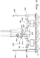
- the calibrated coupling station 500 comprises at least one grip element 501 that is aligned with a predefined stop area of at least one through seat 143.
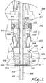
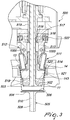
- the grip element 501 comprises a terminal end 502 and can move, by way of the action of a first actuation assembly, from a raised configuration, in which the terminal end 502 faces and is proximate to the seat 143, surmounting it, to a lowered configuration, in which the terminal end 502 rests against an inner surface of the bottom 503 of the bag 13, which in turn is juxtaposed against an inner face of the base 504 of the external body 11.
- the grip element 501 further defines an intermediate configuration for calibrated positioning, in which the terminal end 502 stably coupled to the bottom 503 of the bag 13 is arranged at a predefined distance from the inner face of the base 504 of the external body 11.
- the grip element 501 is substantially aligned with a heat-sealing assembly 511.
- the intermediate configuration allows to position precisely the bag 13 with respect to the external body 11.
- the station 500 may further comprise at least one lower retention member 505, which is aligned with a predefined stop area of at least one through seat 143: obviously, said stop area will be the same one at which the advancement means 14 have stopped in alignment with the grip element 501.
- the lower retention member 505 has a terminal end 506 and can move, by way of the action of a second actuation assembly, from a lowered configuration, in which the terminal end 506 is spaced from the seat 143, to a raised configuration, in which the terminal end 506 contacts and supports the external body 11 at an external face of the base 504.
- the lower retention member 505 and the grip element 501 define together the intermediate configuration for calibrated placement in which the terminal end 502 of the grip element 501 (which is coupled stably to the bottom 503 of the bag 13) is arranged at a predefined distance from the inner face of the base 504 of the external body 11 (said base 504 having an external face which in turn is coupled stably to the terminal end 506 of the lower retention member 505).
- the at least one grip element 501 and the at least one lower retention member 505 respectively comprise a first hollow shaft 507 and a second hollow shaft 508, which translate, with respect to the frame 12, in a direction that is perpendicular to a plane that contains the articulated sector provided with the seat 143: translation is possible by way of the presence of respective actuators, of a known type, which are not shown in the accompanying figures (since they are irrelevant for the definition of the characteristics of the present invention).
- the first hollow shaft 507 and the respective actuator constitute the first actuation assembly of the grip element 501, while the second hollow shaft 508 and the respective actuator constitute the second actuation assembly of the retention member 505.
- the shafts 507 and 508 are provided with internal cavities 509 and 510 that lead, with the interposition of flow control valves controlled by means of a specific control and management unit, to respective pneumatic circuits in partial vacuum.
- the cavities 509 and 510 have, at the respective terminal ends 502 and 506, corresponding openings toward the outside environment.
- the grip elements 501 and the retention members 505 act as suckers in order to retain respectively the bag 13 and the external body 11.
- the terminal end 502 of the grip element 501 and the terminal end 506 of the lower retention member 505 have a substantially disk-like shape, with a diameter that is close to that of the inner surface of the bottom 503 of the bag 13 and of the external face of the base 504 of the external body 11, respectively.
- the terminal end 502 of the grip elements 501 in fact must have a diameter that is similar to, or slightly smaller than, the diameter of the bottom 503 of the bag 13, while the terminal end 506 has a diameter that is preferably close to that of the base 504 of the body 11 (in this second case, the diameter of the terminal end might also be greater or smaller than that of the bottom of the body 11, so long as it is large enough to ensure a firm grip on the base 504 of said external body 11).
- the coupling station 500 also comprises a heat-sealing assembly 511, which is fitted on the shaft 507 and can translate coaxially along it by way of the action of a respective actuator (the actuator is not described specifically and is not shown in the accompanying figures, since it can be any linear actuator of a known type).
- the heat-sealing assembly 511 is provided with a carousel 512, which comprises respective sectors 513 that are pivoted around respective pivots 1000 and define a tubular cover.
- a respective heat-sealing wing 514 is arranged at a first end of each sector 513.
- the sectors 513 are pivoted to the carousel 512 ensures that they can move, arranging their end provided with the respective heat-sealing wing 514 proximate to said carousel 512 (defining the minimum radial space occupation that is needed to perform the translations without interfering with any other component and/or with the external body 11 or with the bag 13) or at a predefined radial distance from the carousel 512 (defining the maximum radial space occupation required to achieve the sealing of the bag 13 on the external body 11, as will become better apparent hereinafter).
- the sectors 513 are pivoted to the carousel 512 at the pivots 1000, which are arranged substantially proximate to the centerline of said sectors 513. This means that the sectors 513 can rotate about the respective pivots 1000, varying the distance between their ends and the carousel 512.
- each sector is provided with a heat-sealing wing 514, which thus can move from a first limit configuration of maximum distance from the carousel 512 (which corresponds to a radial spacing from the carousel 512 due to a rotation of the sector 513 with respect to its own pivot 1000), to a second limit configuration of minimum distance from the carousel 512 (which corresponds to a radial approach to the carousel 512 caused by a rotation, which is opposite with respect to the one described previously, of the sector 513 with respect to its own pivot 1000).
- the carousel 512 can translate coaxially to the shaft 507 along a sleeve 515, which also can move with respect to the frame 12 along a predefined stroke that is independent with respect to the stroke of the shaft 507.
- the sector 513 is provided with a respective feeler 517, which is forced elastically against a contoured section 518 of the sleeve 515.
- the feeler 517 translates radially with respect to the shaft 507, continuing to rest against the contoured section 518, with consequent rotation of the corresponding sector 513 about the pivot 1000.
- the rotation of the sector 513 occurs between the second limit configuration (already defined previously), in which the heat-sealing wings 514 face and are proximate to an inner lateral surface 519 of the bag 13 (which corresponds to a minimal radial space occupation) and a first limit configuration (already defined previously), in which the heat-sealing wings 514 abut by elastic forcing against the inner lateral surface 519, pressing an external lateral surface of the bag 13 against the inner side wall 520 of the external body 11 (which corresponds to a maximum radial space occupation).
- the heat-sealing assembly 511 comprises a plug 521, which is arranged substantially below the heat-sealing wings 514 in order to widen the bag 13 at the second limit configuration (minimum radial space occupation) and in order to ensure that during the translation of the heat-sealing assembly 511 toward the bag 13 the heat-sealing wings 514 do not collide with the bag 13 and do not move said bag 13 with respect to the external body 11.
- the plug 521 is substantially frustum-shaped and ensures that the lateral wall of the bag 13 is pressed against the inner side wall 520 of the external body 11, in order to ensure that the subsequent mutual heat-sealing operations (provided by the heat-sealing wings 514) are performed precisely on correctly juxtaposed surfaces.
- Elastic elements 522 are interposed between the second end 516 of the sector 513 and the carousel 512 and force the feeler 517 on the contoured section 518 of the sleeve 515.
- the contoured sleeve 515 constitutes a cam for the feeler 517, which behaves like a cam follower.
- the feeler 517 undergoes movements in a radial direction by sliding on the sleeve 515 and therefore defines the rule of motion according to which the rotations of each sector 513 about the pivot 1000 occur.
- Each feeler 517 comprises a free roller, which can rotate freely on the contoured sleeve 515: this ensures that the sliding of the feeler 517 occurs on the contoured section 518, minimizing friction (the feeler 517 thus acts as a cam follower of the rolling type).
- the present invention further defines a calibrated coupling method for components of capsules comprising an external body 11, i.e., a non-permeable shell-shaped container, and a bag 13, i.e., a substantially frustum-shaped filter.
- the method according to the invention comprises a plurality of consecutive steps.
- a first step aligns a through seat 143 that accommodates the external body 11, which in turn supports the bag 13, with an upper grip element 501 and with a lower retention member 505.
- a second step it is necessary to make the terminal end 502 of the grip element 501 match up with the inner surface of the body 503 of the bag 13 and make the terminal end 506 of the lower retention member 505 match up with the external face of the base 504 of the body 11.
- This step must be performed while retaining the bottom 503 with the grip element 501 and the base 504 with the lower retention member 505 in conditions of overlap and mutual contact.
- the grip element 501 retains the bottom 503 and the lower retention member 505 retains the base 504 preferably by means of channeled pneumatic suction.
- a third step it is necessary to provide the spacing, according to a predefined distance, of the bottom 503, retained by the terminal end 502 of the lower retention member 505, from the base 504, which is retained by the terminal end 506 of the grip element 501.
- Said third step allows to define precisely the distance of the bottom 503 of the bag 13 from the base 504 of the external body 11, a parameter which must characterize with extreme precision the capsule in its final version.
- said third step allows to define a distance between an inner face of the base 504 of the external body 11 and an external surface of the bottom 503 of the bag 13.
- the stable coupling of the fourth step is provided by heat-sealing the bag 13 to the body 11.
- the present invention relates further to an apparatus 10 for preparing a product in single-use capsules for respective infusion machines to obtain a corresponding beverage, preferably in the form of coffee or based on coffee, particularly to obtain a filter coffee.
- the capsule is of the type that comprises an external supporting body 11, preferably having the general shape of a frustum-like cup, which is adapted to accommodate and retain internally a respective bag 13, which in particular is shaped like a cupcake liner, which in turn is adapted to contain a dose of product.
- the bag 13 is preferably made of a suitable porous or filtering material, for example filter paper.
- the external supporting body 11 of the capsule is conveniently contoured so as to be arranged in corresponding contoured cavities of the infusion machine during the operation for infusion of the beverage.
- the bag 13 comprises a preferably circular bottom, from which a peripheral wall protrudes which is flared in a direction that is transverse to the bottom, is concertina shaped (pleated) and is obtained by means of a plurality of longitudinal folding lines.
- the apparatus 10 comprises means 14 for the advancement of the external body 11 or of the capsule being prepared, which can move along an advancement direction A, along a respective operating path between various operating stations of the apparatus.
- the advancement means 14 are preferably in the form of an endless conveyor belt 141 with articulated sectors, which can rotate on respective end wheels, of which only one, designated by the reference numeral 142, is shown in the accompanying figures.
- the endless conveyor belt 141 defines a plurality of cavities or seats 143 for the accommodation and support of a respective external body 11 of the capsule.
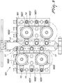
- the presence is provided of a plurality of parallel rows of seats 143 along the advancement direction A (in the illustrated embodiment the parallel rows are six in mumber) for the simultaneous and parallel advancement of a plurality of external bodies 11 or capsules being prepared.
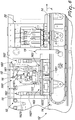
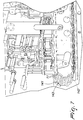
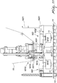
- the apparatus 10 comprises further, in sequence along the advancement direction A, a station 16 for providing and inserting the bag 13 inside the external body 11 of the capsule, a joining station 18 for joining, in particular for heat-sealing, the bag 13 to the external body 11 of the capsule, a filling station 20 for filling the bag with a dose of product, and a closure station 21 (shown schematically in Figure 1 ) to close the external body 11 with a closure sheet.
- the apparatus 10 comprises further a fixed frame 12, which supports the advancement means 14, the station 16 for the provision and insertion of the bag 13, the joining station 18, the filling station 20 and the closure station 21.
- the station 16 for the provision and insertion of the bag 13 comprises at least one working unit 160 for providing and inserting the bag 13, which comprises respectively a device 161 for providing the bag 13, a device 162 for inserting the bag 13 in the external body 11 of the capsule, and a device 163 for conveying the bag 13 in order to convey the bag 13 from the provision device 161 to the insertion device 162.
- the apparatus 10 comprises a first working unit and a second working unit 160, 160 for the provision and insertion of the bag 13, which comprise respectively a first device and a second device 161 for providing the bag 13, a first device and a second device 162 for inserting the bag 13 in the external body 11 of the capsule, and a first device and a second device 163 for conveying the bag 13, in order to convey the bag 13 from the first and second provision device 161 to the first and second insertion device 162 respectively.
- the respective devices 161, 161 for providing the bag and the respective devices 162, 162 for inserting the bag 13 in the external body 11 of the capsule are mutually spaced along the advancement direction A and in particular are mutually spaced longitudinally.
- the first device 162 for inserting the bag 13 within the external body 11 of the capsule is provided upstream with respect to the first device 161 for providing the same bag along the advancement direction A.
- the second device 162 for inserting the bag 13 is provided downstream with respect to the second device 161 for providing the bag 13 along the advancement direction A.
- the first and second units 160, 160 for providing and inserting the bag 13 within the external body 11 of the capsule operate on a single ribbon 15 of filter material.
- first and second units 160, 160 for providing and inserting the bag 13 are mutually adjacent along the advancement direction A and are transversely offset, particularly transversely offset by a row of seats 143.
- the supporting frame 12 comprises an intermediate wall 121, which in particular is extended longitudinally and separates actuations 9 of the apparatus 10 from the working stations of the apparatus.
- the reference numeral 151 designates guiding rollers for the path of the ribbon 15 of filter material toward and from the operating units 160.
- the first unit 160 for the provision and insertion of the bags 13 acts on first external bodies 11 of capsules
- the second unit 160 for the provision and insertion of the bags 13 acts on second external bodies 11 of capsules, the first external bodies 11 of capsules being offset with respect to the second external bodies 11 of capsules along the advancement direction A, particularly transversely to the advancement direction A.
- respective parts or components of the first and second operating units 160, 160 for the provision and insertion of the bags 13 are mutually offset transversely to the advancement direction A.
- the first working unit 160 operates on three first external bodies 11, while the second unit 160 acts on three second external bodies 11, which however are arranged on rows that are interposed or staggered with respect to the rows of the first three external bodies 11 on which the first unit 160 works.
- first and second devices 161, 161 for providing the bags 13 of the first unit and of the second unit 160, 160 are provided mutually adjacent so as to separate, in particular cut, from a single ribbon 15 of filter material corresponding portions 17, particularly having a disk-like or circular shape, in order to provide corresponding bags 13.
- the devices 161, 161 for providing the bag of the first and second units 160, 160 comprise respective elements 1610 for cutting respective portions 17 for bags 13, said cutting elements 1610 being arranged so as to provide respectively first portions 17 and second portions 17.
- the first portions 17 and the second portions 17 are mutually spaced along the advancement direction A and are mutually offset along a direction that is transverse to the advancement direction A.
- the cutting elements 1610 of the first devices 161 for providing the first working unit 160 are substantially aligned along a first direction Y1, which is advantageously perpendicular to the advancement direction A of the external bodies 11, while the cutting elements 1610 of the second provision devices 161 of the second working unit 160 are substantially aligned along a second direction Y2, which is parallel to the first direction Y1 and advantageously perpendicular to the advancement direction A.
- the first portions 17 provided by the cutting elements 1610 of the first provision devices 161 of the first working unit 160 have centers that lie on the first direction Y1
- the second portions 17 for a bag provided by the cutting elements 1610 of the second provision devices 161 of the second working unit 160 have centers that lie on the second direction Y2, respectively.
- first direction Y1 and the second direction Y2 are spaced by less than the diameter of a portion 17 for a bag.
- the cutting elements 1610 can be adapted to provide portions 17 that have a noncircular shape.
- the cutting elements 1610 of the first provision device 161 provide first noncircular portions 17 that are aligned along the first direction Y1
- the cutting elements 1610 of the second provision device 161 provide second noncircular portions 17 that are aligned along the second direction Y2, the first direction Y1 and the second direction Y2 being spaced by less than a maximum distance along the advancement direction A of the noncircular portions 17.
- providing the cutting elements 1610 of the first working unit 160 and the cutting elements 1610 of the second working unit 160 so that they are offset transversely to the advancement direction A allows to minimize waste.
- the cutting elements 1610 comprise a blade or punch 1611, which is advantageously circular and cooperates with a complementary blade or die 1612.
- the die 1612 is advantageously arranged at an upper end of formation means, advantageously a formation hopper 1613, in which the portion 17 for the bag 13 is pushed by pusher means so as to be shaped correspondingly like a cupcake liner.
- the pusher means comprise a corresponding piston 1614.
- the piston 1614 can move coaxially to the respective punch 1611.
- the device 161 for providing the bag 13 comprises, therefore, at least one piston 1614 adapted to engage a face, particularly an upper face, of the portion 17 for the bag and to push said portion 17 for the bag into the corresponding formation means, advantageously into the formation hopper 1613.
- the device 161 for providing the bag 13 comprises following elements, which cooperate with the pusher means, in order to follow the portion 17 for the bag through the corresponding shaping means 1613.
- the following elements comprise an additional piston 1615, which is adapted to engage a face, particularly a lower face, of the portion 17 for the bag.
- the additional piston 1615 is adapted to follow the portion 17 for the bag through the formation hopper 1613.
- the additional piston 1615 can move between a raised position, in which it is extended within the formation hopper 1613, and a lowered position for transferring the cupcake liner-shaped bag 17 to the conveyance device 163.
- the additional piston 1615 is moved in phase coordination with the piston 1614 in order to convey the portion 17 gradually into the formation means 1613.
- the additional piston 1615 is moved in phase coordination with the piston 1614 in order to clamp and force the portion 17 within the formation means or formation hopper 1613.
- the portion 17 is retained by and between the pusher means and the following elements, advantageously between the piston 1614 and the additional piston 1615.
- the formation hopper 1613 comprises adapted protrusions for bending the portion 17 like a cupcake liner.
- the additional piston 1615 while it accompanies the portion 17, by moving vertically, passes through a corresponding seat 1631 of the conveyance devices 163 that is arranged below the formation hopper 1613.
- the conveyance device 163 moves on a horizontal plane.
- said horizontal plane is parallel to a plane on which the external bodies 11 of the capsules lie, i.e., above the means 14 for the advancement of the external bodies 11 and below the formation hopper 1613.
- the conveyance device 163 comprises an endless supporting belt 1632, which is supported by corresponding toothed pulleys for driving and traction 1633, said endless supporting belt 1632 supporting a plurality of seats 1631, which are adapted to be arranged alternatively at the provision means 161 and at the insertion means 162.
- the endless supporting belt 1632 moves the plurality of seats 1631 on a horizontal plane that is parallel to the advancement direction A, i.e., above the advancement means 14 of the external bodies 11 and below the formation hopper 1613.
- the respective seat 1631 of said conveyance means 163 comprises a corresponding through hole for accommodating the bag 13, which is sized appropriately in order to retain by interference the respective bag 13.
- the apparatus shown in the figures comprises a first conveyance device 163 and a second conveyance device 163, which comprise respectively a first endless supporting belt and a second endless supporting belt 1632, which rotate in opposite directions on a horizontal plane above the advancement means 14.
- the endless supporting belts rotate in the same direction.
- Each endless supporting belt 1632 supports at least one seat 1631.
- each belt supports a plurality of seats 1631.
- first endless supporting belt 1632 supports a first series of seats 1631 and the second endless supporting belt 1632 supports a second series of seats 1631.
- the first series of seats 1631 conveys the bags 13 from the first provision device 161 of the first working unit 160 upstream of the advancement direction A at the first insertion device 162, while the second series of seats 1631 conveys the bags 13 from the second provision device 161 of the second working unit 160 downstream with respect to the advancement direction A at the second device for insertion of the bag 162.
- the first and second devices 162, 162 for insertion of the bag 13 within the external body 11 of the capsule comprise respective first and second means for engaging and pushing the bag shaped like a cupcake liner within the respective external body 11 of the capsule.
- the means for engaging and pushing the cupcake liner-shaped bag into the respective external body 11 of the capsule comprise respective pushers, for example respective pistons that pass through the respective seat 1631 for supporting the conveyance devices 163.
- the engagement and pushing devices are also adapted to pass through a corresponding tubular body 1622 that is provided between the respective supporting seat 1631 of the conveyance devices 163 and the accommodation and support seat 143 of the advancement means 14.
- the means for engaging and pushing the cupcake liner-shaped bags into the respective external body of the capsule are supported by a corresponding and common frame 1623, which is actuated by a corresponding crank system 1624.
- the first and second engagement and pushing means each comprise three pushers 1621.
- the pushers 1621 are actuated along vertical directions, in order to push downward the bags 13 within a respective external body 11.
- the pushers 1621 are adapted to push the bottom 503 of the bag 13 into contact with the base 504 of the external body 11.
- the pushers 1621 make contact with (and support) the inner surface of the bottom 503 of the bag 13 and move the external surface of the bottom 503 of said bag 13 into contact with the inner face of the base 504 of the external body 11.
- the pushers 1621 of the first and second engagement and pushing means are arranged on rows that are transverse to the advancement direction A of the external bodies 11.
- the pushers 1621 of the first engagement and pushing means are arranged along a first row upstream of the respective first device 161 for providing the bag 13, while the pushers 1621 of the second engagement and pushing means are arranged along a second row downstream of the respective second device 161 for providing the bag 13.
- the pushers 1621 of the first row are arranged in alternating rows of seats 143 and likewise the pushers 1621 of the second row are arranged on rows of seats 143 that are alternated and different from those of the first row of pushers 1621.
- a method for preparing a product for infusion or extraction in a capsule advantageously a single-use capsule for infusion or extraction beverages, which comprises an external body 11 and a bag 13 of suitable porous and/or filtering material that is shaped like a cupcake liner.
- the method further comprises the steps of feeding a plurality of external bodies 11 of capsules according to a plurality of parallel rows within respective seats 143 of means 14 for advancement along an advancement direction A; of feeding a ribbon 15 of filter material; of obtaining by cutting from the ribbon of filter material a plurality of portions 17 adapted to provide a bag shaped like a cupcake liner; bending the portions 17 so as to form corresponding bags 13 shaped like a cupcake at a device 161 for providing the bag 13; inserting the bags 13 in corresponding seats 1631 of a conveyance device 163; moving the seats 1631 upstream or downstream of the device 161 for providing the bag 13 with respect to the advancement direction A in order to position the bags 13 above corresponding external bodies 11; and inserting the bags 13 within corresponding external bodies 11 that are accommodated within respective seats 143 of the advancement means 14.
- the step of bending the portions 17 so as to form corresponding bags 13 shaped like cupcake liners comprises clamping the portions 17 between pusher means, for example a piston 1614, which are adapted to engage an upper face of the portion 17, and engagement means, for example an additional piston 1615, which is adapted to engage a lower face of the portion 17 and force the portion 17 thus clamped within formation means, for example a formation hopper 1613.
- pusher means for example a piston 1614
- engagement means for example an additional piston 1615, which is adapted to engage a lower face of the portion 17 and force the portion 17 thus clamped within formation means, for example a formation hopper 1613.
- the step of providing by cutting from the ribbon 15 of filter material a plurality of portions 17 adapted to provide a bag 13 shaped like a cupcake liner comprises providing, by cutting, first portions 17 that are aligned along a first direction Y1 and second portions 17 that are aligned along a second direction Y2 that is parallel to the first direction Y1.
- first direction Y1 and said second direction Y2 are mutually parallel and transverse to the advancement direction A.
- first portions 17 and second portions 17 are offset with respect to the second portions 17 along a direction that is perpendicular to the advancement direction A.
- the method comprises inserting the bags 13 provided from the first portions 17 within first external bodies 11 and the bags 13 provided from the second portions 17 within second external bodies 11, the first external bodies 11 being offset along the advancement direction A with respect to the second external bodies 11.
- the first external bodies 11 are arranged upstream of the second external bodies 11.
- the present invention solves the problems described previously, by devising a calibrated coupling station 500 for components of capsules that allows to establish precisely the mutual position of the external body 11 and of the bag 13.
- the calibrated coupling station 500 ensures production with a provision quality that is constant over time by way of the retention of the body 11 and of the bag 13 respectively by way of the retention member 505 and of the grip element 501 and their mutual blocking by means of a plug 521 before performing heat-sealing.
- the apparatus 10 ensures the correct provision of the frustum-like shape with pleated side walls (a so-called "cupcake liner" configuration) of the bag 13 in order to avoid problems of incorrect heat-sealing thereof to the body 11, producing a reduction of the quantity of packages of poor quality or to be discarded that are produced with a corresponding reduction of consequent machine downtimes.
- the apparatus 10 does not require the use of complex and expensive devices for arranging/placing the bag 13 within the body 11.
- the apparatus 10 ensures that the provision and insertion of the bag 13 in the external body 11 are simple and do not require components that entail difficult assembly and complex maintenance and repair.
- the insertion of the bag 13 in the body 11 is total, i.e., the bag 13 is inserted fully within the body 11, since the correct mutual arrangement of said two components is performed subsequently, in the station 500, which allows to move the bottom 503 and the base 504 to the predefined distance set by the design, particularly to space the bottom 503 from the base 504.
- the station 500 for calibrated coupling and the apparatus 10 for packaging said capsule components have low costs and are relatively simple to provide in practice and safe in application.
- the materials used, as well as the dimensions, may be any according to requirements and to the state of the art.
Landscapes
- Engineering & Computer Science (AREA)
- Mechanical Engineering (AREA)
- Textile Engineering (AREA)
- Chemical & Material Sciences (AREA)
- Composite Materials (AREA)
- Apparatus For Making Beverages (AREA)
Claims (13)
- Eine kalibrierte Kopplungsstation (500) für Komponenten von Kapseln von der Art, die einen externen Körper (11) und eine Tasche (13) aus Filtermaterial umfasst, wobei die Station einen durchgehenden Sitz (143) zur festen Aufnahme des externen Körpers (11) umfasst, der die Tasche (13) trägt, angeordnet an einem gelenkigen Abschnitt entsprechender Vorschubmittel (14), beweglich entlang einem Rahmen (12), und mindestens ein Greifelement (501), ausgerichtet mit einem vordefinierten Anschlagsbereich des durchgehenden Sitzes (143) und das ein terminales Ende (502) umfasst, wobei das Greifelement (501) mit Hilfe eines entsprechenden ersten Antriebsaufbaus beweglich ist aus einer erhöhten Anordnung, in welcher das terminale Ende (502) dem durchgehenden Sitz (143) zugewandt ist und an ihn angrenzt, wobei das terminale Ende (502) oberhalb des durchgehenden Sitzes (143) angeordnet ist, in eine abgesenkte Anordnung, in welcher das terminale Ende (502) auf einem Boden (503) der Tasche (13) aufliegt, wiederum an eine Innenfläche einer Basis (504) des externen Körpers (11) angrenzend, dadurch gekennzeichnet, dass
das Greifelement (501) eine intermediäre Anordnung für die kalibrierte Positionierung hat, in welcher das terminale Ende (502), fest mit dem Boden (503) der Tasche (13) gekoppelt, in einem vordefinierten Abstand von der Innenfläche der Basis (504) des externen Körpers (11) angeordnet ist, wobei das Greifelement (501), in der intermediären Anordnung für die kalibrierte Positionierung der Tasche (13) im Verhältnis zu dem externen Körper (11), im Wesentlichen mit einem Heißsiegelaufbau (511) ausgerichtet ist, der ausgebildet ist, um die Tasche (13) und den externen Körper (11) in einer gegenseitigen Anordnung, die durch die intermediäre Anordnung bestimmt wird, fest zu koppeln. - Die Station gemäß Anspruch 1, dadurch gekennzeichnet, dass sie mindestens ein unteres Halteglied (505) umfasst, ausgerichtet mit dem vordefinierten Anschlagsbereich des durchgehenden Sitzes (143), wobei das untere Halteglied (505) ein entsprechendes terminales Ende (506) umfasst und durch die Wirkung eines entsprechenden zweiten Antriebsaufbaus beweglich ist aus einer absenkten Anordnung, in welcher das entsprechende terminale Ende (506) des unteren Haltegliedes (505) dem durchgehenden Sitz (143) zugewandt ist und an ihn angrenzt, wobei das entsprechende terminale Ende (506) des unteren Haltegliedes (505) unterhalb des durchgehenden Sitzes (143) angeordnet ist, in eine erhöhte Anordnung, in welcher das entsprechende terminale Ende (506) des unteren Haltegliedes (505) eine äußere Fläche der Basis (504) des externen Körpers (11) berührt; wobei das untere Halteglied (505) und das Greifelement (501) die intermediäre Anordnung für die kalibrierte Positionierung bestimmen, in welcher das terminale Ende (502) des Greifelements (501), fest mit dem Boden (503) der Tasche (13) gekoppelt, in einem vordefinierten Abstand von der Innenfläche der Basis (504) des externen Körpers (11) angeordnet ist, deren Außenfläche fest mit dem terminalen Ende (506) des unteren Haltegliedes (505) gekoppelt ist.
- Die Station gemäß Anspruch 2, dadurch gekennzeichnet, dass das mindestens eine Greifelement (501) und das mindestens eine untere Halteglied (505) eine erste Hohlwelle (507) beziehungsweise eine zweite Hohlwelle (508) umfassen, die mit Hilfe entsprechender Antriebselemente im Verhältnis zu dem Rahmen (12) eine Translationsbewegung in eine Richtung durchführen, die senkrecht zu einer Ebene ist, welche den gelenkigen Abschnitt enthält, der mit dem durchgehenden Sitz (143) ausgestattet ist, wobei die erste und die zweite Hohlwelle (507, 508), die die Translationsbewegung mit Hilfe der entsprechenden Antriebselemente durchführen, den ersten Antriebsaufbau beziehungsweise den zweiten Antriebsaufbau bilden.
- Die Station gemäß Anspruch 3, dadurch gekennzeichnet, dass die erste und die zweite Hohlwelle (507, 508) entsprechende Innenhohlräume (509, 510) haben, die, mit Zwischenschaltung von Durchflussregelungsventilen, zu entsprechenden Pneumatikkreisläufen in Teilvakuum führen und an entsprechenden terminalen Enden (502, 506) entsprechende Öffnungen zur äußeren Umgebung hin haben.
- Die Station gemäß einem beliebigen der obigen Ansprüche, dadurch gekennzeichnet, dass das terminale Ende (502) des Greifelements (501) und das terminale Ende (506) des unteren Haltegliedes (505) eine im Wesentlichen scheibenähnliche Form haben, mit einem Durchmesser ähnlich dem Durchmesser des Bodens (503) der Tasche (13) beziehungsweise der Basis (504) des externen Körpers (11), an denen sie in der intermediären Anordnung für die kalibrierte Positionierung aufliegen.
- Die Station gemäß einem beliebigen der obigen Ansprüche, dadurch gekennzeichnet, dass der Heißsiegelaufbau (511) an der ersten Welle (507) montiert ist, durch die Wirkung eines entsprechenden Antriebselements eine koaxiale Translationsbewegung entlang derselben durchführen kann; wobei der Heißsiegelaufbau (511) mit einem Karussell (512) ausgestattet ist, an dem entsprechende Sektoren (513), die eine rohrförmige Abdeckung des Karussells (512) bestimmen, über entsprechende Drehzapfen (1000) aufgehängt sind, wobei der Heißsiegelaufbau (511) Heißsiegelflügel (514) umfasst, die an einem ersten Ende der Sektoren (513) angebracht sind.
- Die Station gemäß Anspruch 6, dadurch gekennzeichnet, dass das Karussell (512) koaxial mit der ersten Welle (507) eine Translationsbewegung entlang einer Hülse (515) durchführen kann, die ebenfalls mit einem Hub beweglich ist, der vordefiniert und von der ersten Welle (507) unabhängig ist; wobei an einem zweiten Ende (516) des Sektors (513), das dem ersten, mit den Heißsiegelflügeln (514) versehenen Ende gegenüberliegt, ein Fühler (517) angebracht ist, der elastisch gegen einen konturierten Abschnitt (518) der Hülse (515) gedrückt wird; wobei bei einer vertikalen Translation der Hülse (515), wenn das Karussell (512) bewegungslos ist, der Fühler (517) eine Translationsbewegung in eine radiale Richtung mit Bezug auf die erste Welle (507) durchführt, dabei in Auflagekontakt mit dem konturierten Abschnitt (518) bleibt, mit daraus folgender Drehung eines entsprechenden Sektors (513) um den entsprechenden Drehzapfen (1000) zwischen einer zweiten Grenzposition, in welcher die Heißsiegelflügel (514) einer inneren Seitenfläche (519) der Tasche (13) zugewandt sind und an sie angrenzen, und einer ersten Grenzposition, in welcher die Heißsiegelflügel (514) durch elastisches Drücken an die innere Seitenfläche (519) der Tasche (13) anstoßen, sie gegen eine innere Seitenwand (520) des externen Körpers (11) drückend.
- Die Station gemäß einem beliebigen der Ansprüche 6 und 7, dadurch gekennzeichnet, dass der Heißsiegelaufbau (511) einen Stopfen (521) umfasst, der im Wesentlichen unterhalb der Heißsiegelflügel (514) angeordnet ist, um eine äußere Seitenfläche der Tasche (13) gegen die innere Seitenwand (520) des externen Körpers (11) zu drücken, in der ersten Grenzposition, in der die Heißsiegelflügel (514) durch elastisches Drücken an die innere Seitenfläche (519) der Tasche (13) anstoßen, die äußere Seitenfläche der Tasche (13) gegen die innere Seitenwand (520) des externen Körpers (11) drückend.
- Die Station gemäß einem beliebigen der obigen Ansprüche, dadurch gekennzeichnet, dass die elastischen Elemente (522) zwischen dem zweiten Ende (516) des Sektors (513) und dem Karussell (512) angeordnet sind, um den Fühler (517) gegen den konturierten Abschnitt (518) der Hülse (514) zu drücken, der einen Nocken bildet.
- Die Station gemäß einem beliebigen der obigen Ansprüche, dadurch gekennzeichnet, dass der Fühler (517) eine Leitrolle umfasst, die sich frei auf dem konturierten Abschnitt (518) der Hülse (514) drehen kann.
- Ein kalibriertes Kopplungsverfahren für Komponenten von Kapseln, die einen externen Körper (11) umfassen, ausgestattet mit einer Basis (504) und einer mit einem Boden (503) versehenen Tasche (13), wobei die Tasche (13) von dem externen Körper (11) getragen wird; dadurch gekennzeichnet, dass das Verfahren folgende Schritte umfasst:- Ausrichten eines durchgehenden Sitzes (143), der den externen Körper (11) aufnimmt, welcher die Tasche (13) trägt, mit einem Greifelement (501), ausgebildet, um die Tasche (13) zu halten, und mit einem unteren Halteglied (505), ausgebildet, um den externen Körper (11) zu tragen,- Koppeln eines terminalen Endes (502) des Greifelements (501) mit einer Innenfläche des Bodens (503) der Tasche (13) und Koppeln eines terminalen Endes (506) des unteren Haltegliedes (505) mit einer Außenfläche der Basis (504) des externen Körpers (11), wobei der Boden (503) mit dem Greifelement (501) und die Basis (504) mit dem unteren Halteglied (505) so gehalten werden, dass sie übereinanderliegen und im Kontakt miteinander stehen,- Beabstanden des Bodens (503) von der Basis (504) um einen vordefinierten Abstand,- festes Koppeln der Tasche (13) mit dem externen Körper (11) .
- Eine Vorrichtung zur Herstellung von Kapseln, die ein Aufguss- oder Extraktionsprodukt enthält und einen externen Körper (11) und eine Tasche (13) aus porösem und/oder Filtermaterial umfasst, die wie eine Muffinform geformt ist; wobei die Vorrichtung einen Stützrahmen (12), Vorschubmittel (14) zum Bewegen des externen Körpers (11) entlang einer Vorschubrichtung (A) und eine Bereitstellungs- und Einsetzeinheit (160) zum Bereitstellen und Einsetzen der Tasche (13) in den externen Körper (11) umfasst; dadurch gekennzeichnet, dass die Bereitstellungs- und Einsetzeinheit (160) eine Bereitstellungsvorrichtung (161) zum Bereitstellen der Tasche (13) umfasst, eine Einsetzvorrichtung (162) zum Einsetzen der Tasche (13) in den externen Körper (11) und eine Beförderungsvorrichtung (163) zum Befördern der Tasche (13) von der Bereitstellungsvorrichtung (161) zur Einsetzvorrichtung (162); wobei die Bereitstellungsvorrichtung (161) entlang der Vorschubrichtung (A) stromaufwärts oder stromabwärts von der Einsetzvorrichtung (162) angeordnet ist, und dadurch gekennzeichnet, dass sie eine kalibrierte Kopplungsstation (500) für Komponenten von Kapseln entsprechend einem beliebigen der Ansprüche 1-10 umfasst.
- Die Vorrichtung gemäß Anspruch 12, dadurch gekennzeichnet, dass die Bereitstellungsvorrichtung (161) ausgebildet ist, um von einem einzigen Materialstreifen (15) für Taschen entsprechende Teile (17) abzutrennen, insbesondere abzuschneiden, die insbesondere eine Scheibenform oder Kreisform haben, um entsprechende Taschen (13) zu liefern.
Applications Claiming Priority (2)
| Application Number | Priority Date | Filing Date | Title |
|---|---|---|---|
| ITBO20140314 | 2014-05-28 | ||
| PCT/IB2015/053867 WO2015181705A1 (en) | 2014-05-28 | 2015-05-25 | Calibrated coupling station for components of capsules and apparatus for preparing such capsules |
Publications (2)
| Publication Number | Publication Date |
|---|---|
| EP3148882A1 EP3148882A1 (de) | 2017-04-05 |
| EP3148882B1 true EP3148882B1 (de) | 2018-07-04 |
Family
ID=51220652
Family Applications (1)
| Application Number | Title | Priority Date | Filing Date |
|---|---|---|---|
| EP15734443.3A Active EP3148882B1 (de) | 2014-05-28 | 2015-05-25 | Kalibrierte kupplungsstation für bauteile von kapseln und vorrichtung zur herstellung solcher kapseln |
Country Status (4)
| Country | Link |
|---|---|
| US (1) | US10875673B2 (de) |
| EP (1) | EP3148882B1 (de) |
| CA (1) | CA2950243C (de) |
| WO (1) | WO2015181705A1 (de) |
Families Citing this family (12)
| Publication number | Priority date | Publication date | Assignee | Title |
|---|---|---|---|---|
| US11745906B2 (en) * | 2015-11-23 | 2023-09-05 | Cupper Llc | System, apparatus, and method for preparing a beverage cartridge |
| CN208791164U (zh) * | 2015-11-23 | 2019-04-26 | Mb2杯子发展有限责任公司 | 用于制备饮料胶囊的系统和装置 |
| US12121176B2 (en) * | 2015-11-23 | 2024-10-22 | Cupper Llc | System, apparatus and method for preparing a beverage cartridge |
| DE102016114650A1 (de) * | 2016-08-08 | 2018-02-08 | Gerhard Schubert Gmbh | Kapsel-Füll- Maschine und Verfahren zum Füllen von Kapseln mit einem Pulver |
| IT201700011624A1 (it) * | 2017-02-02 | 2018-08-02 | Ica Spa | Macchina e metodo per formare capsule con corpo capsula plissettato |
| WO2019204914A1 (en) * | 2018-04-23 | 2019-10-31 | 2266170 Ontario Inc. | Capsules, beverage brewing systems and fabrics with optimum filtration characteristics |
| IT201800010250A1 (it) * | 2018-11-12 | 2020-05-12 | Opem S P A | Apparato per il confezionamento di capsule in sottovuoto |
| IT202000018871A1 (it) * | 2020-07-31 | 2022-01-31 | Gd Spa | Unità, metodo ed apparato di accoppiamento tra un componente ed un contenitore |
| EP4192744B1 (de) * | 2020-08-05 | 2025-09-03 | G.D S.p.A. | Herstellungsvorrichtung und herstellungsverfahren für kapseln vom infusionstyp |
| US12312112B2 (en) * | 2020-09-15 | 2025-05-27 | Rychiger Ag | Apparatus for the manufacture of a filter for disposable capsules for the preparation of beverages |
| IT202200024312A1 (it) * | 2022-11-25 | 2024-05-25 | Tecmes Srl | Procedimento di produzione di capsule filtranti di caffe’ e relativa macchina capsulatrice |
| CN116513540A (zh) * | 2023-04-04 | 2023-08-01 | 刘小丰 | 一种咖啡胶囊制造工具及其制造方法 |
Family Cites Families (10)
| Publication number | Priority date | Publication date | Assignee | Title |
|---|---|---|---|---|
| US3385025A (en) * | 1965-10-22 | 1968-05-28 | Jerome H. Lemelson | Packaging machinery and method |
| US4549389A (en) * | 1983-05-05 | 1985-10-29 | Zichy Theodore B R | Precharged containers |
| US5373933A (en) * | 1993-11-09 | 1994-12-20 | Tomra Systems A/S | Conveyor with variable suction force |
| US5517723A (en) * | 1994-09-19 | 1996-05-21 | Sircy; Patricia M. | Hinge pin with insertion tool |
| US20080314256A1 (en) * | 2007-06-21 | 2008-12-25 | Packaging Technologies, Inc. | Filter handling apparatus |
| ITRE20080025A1 (it) * | 2008-02-22 | 2009-08-23 | Opem S P A | Impianto per la fabbricazione di capsule monodose per la preparazione di bevande |
| ITBO20110621A1 (it) * | 2011-11-04 | 2013-05-05 | Ima Ind Srl | Procedimento e macchina per la formazione di una capsula monouso per bevande e capsula cosi' ottenuta. |
| ITBO20120337A1 (it) | 2012-06-20 | 2013-12-21 | Ima Ind Srl | Procedimento e macchina per formare capsule monouso per bevande |
| GB2509046B (en) * | 2012-10-19 | 2016-01-13 | Kraft Foods R & D Inc | Improvement in or relating to capsules |
| ITBO20130406A1 (it) * | 2013-07-26 | 2015-01-27 | P A As | Dispositivo e metodo di assemblaggio di capsule per l'estrazione di bevande. |
-
2015
- 2015-05-25 US US15/314,427 patent/US10875673B2/en active Active
- 2015-05-25 EP EP15734443.3A patent/EP3148882B1/de active Active
- 2015-05-25 WO PCT/IB2015/053867 patent/WO2015181705A1/en not_active Ceased
- 2015-05-25 CA CA2950243A patent/CA2950243C/en active Active
Non-Patent Citations (1)
| Title |
|---|
| None * |
Also Published As
| Publication number | Publication date |
|---|---|
| US20170096243A1 (en) | 2017-04-06 |
| US10875673B2 (en) | 2020-12-29 |
| CA2950243A1 (en) | 2015-12-03 |
| WO2015181705A1 (en) | 2015-12-03 |
| CA2950243C (en) | 2022-04-12 |
| EP3148882A1 (de) | 2017-04-05 |
Similar Documents
| Publication | Publication Date | Title |
|---|---|---|
| EP3148882B1 (de) | Kalibrierte kupplungsstation für bauteile von kapseln und vorrichtung zur herstellung solcher kapseln | |
| EP2825465B1 (de) | Vorrichtung und verfahren zur herstellung von filtern und einsetzen der filter in portionskapseln zur getränkezubereitung | |
| EP2093148B1 (de) | Anlage zur Produktion von Portionskapseln zur Herstellung von Getränken | |
| EP3024735B1 (de) | Vorrichtung und verfahren zur montage von kapseln zur extraktion von getränken | |
| US10315785B2 (en) | Unit and method for filling containers forming single-use capsules for extraction or infusion beverages | |
| EP2935017B1 (de) | Maschine zur herstellung von filterbeuteln für aufbrühbare produkte | |
| EP3177539B1 (de) | Einheit und verfahren zum füllen von einwegkapselbehältern für extraktions- oder aufgussgetränke | |
| US12269630B2 (en) | Production device and production process for infusion type capsules | |
| US20170015078A1 (en) | Apparatus and Method for Pre-Folding Packaging Sleeves | |
| CN105579346B (zh) | 用于将产品包装于由外体及内袋构成的容器中的装置及方法 | |
| WO2018189632A1 (en) | Method and apparatus for making capsules provided with filter | |
| EP4371739A1 (de) | Schweisseinheit für eine maschine zur herstellung von kapseln mit gefaltetem kapselkörper | |
| EP4695158A1 (de) | Verfahren zur herstellung von verpackungen für flüssige oder pastöse produkte und vorrichtung dafür |
Legal Events
| Date | Code | Title | Description |
|---|---|---|---|
| STAA | Information on the status of an ep patent application or granted ep patent |
Free format text: STATUS: THE INTERNATIONAL PUBLICATION HAS BEEN MADE |
|
| PUAI | Public reference made under article 153(3) epc to a published international application that has entered the european phase |
Free format text: ORIGINAL CODE: 0009012 |
|
| STAA | Information on the status of an ep patent application or granted ep patent |
Free format text: STATUS: REQUEST FOR EXAMINATION WAS MADE |
|
| 17P | Request for examination filed |
Effective date: 20161123 |
|
| AK | Designated contracting states |
Kind code of ref document: A1 Designated state(s): AL AT BE BG CH CY CZ DE DK EE ES FI FR GB GR HR HU IE IS IT LI LT LU LV MC MK MT NL NO PL PT RO RS SE SI SK SM TR |
|
| AX | Request for extension of the european patent |
Extension state: BA ME |
|
| DAV | Request for validation of the european patent (deleted) | ||
| DAX | Request for extension of the european patent (deleted) | ||
| GRAP | Despatch of communication of intention to grant a patent |
Free format text: ORIGINAL CODE: EPIDOSNIGR1 |
|
| STAA | Information on the status of an ep patent application or granted ep patent |
Free format text: STATUS: GRANT OF PATENT IS INTENDED |
|
| INTG | Intention to grant announced |
Effective date: 20171206 |
|
| GRAS | Grant fee paid |
Free format text: ORIGINAL CODE: EPIDOSNIGR3 |
|
| GRAA | (expected) grant |
Free format text: ORIGINAL CODE: 0009210 |
|
| STAA | Information on the status of an ep patent application or granted ep patent |
Free format text: STATUS: THE PATENT HAS BEEN GRANTED |
|
| AK | Designated contracting states |
Kind code of ref document: B1 Designated state(s): AL AT BE BG CH CY CZ DE DK EE ES FI FR GB GR HR HU IE IS IT LI LT LU LV MC MK MT NL NO PL PT RO RS SE SI SK SM TR |
|
| REG | Reference to a national code |
Ref country code: GB Ref legal event code: FG4D |
|
| REG | Reference to a national code |
Ref country code: CH Ref legal event code: EP |
|
| REG | Reference to a national code |
Ref country code: AT Ref legal event code: REF Ref document number: 1014225 Country of ref document: AT Kind code of ref document: T Effective date: 20180715 |
|
| REG | Reference to a national code |
Ref country code: IE Ref legal event code: FG4D |
|
| REG | Reference to a national code |
Ref country code: DE Ref legal event code: R096 Ref document number: 602015013086 Country of ref document: DE |
|
| REG | Reference to a national code |
Ref country code: CH Ref legal event code: NV Representative=s name: MODIANO AND PARTNERS S.A., CH |
|
| REG | Reference to a national code |
Ref country code: NL Ref legal event code: MP Effective date: 20180704 |
|
| REG | Reference to a national code |
Ref country code: LT Ref legal event code: MG4D |
|
| REG | Reference to a national code |
Ref country code: AT Ref legal event code: MK05 Ref document number: 1014225 Country of ref document: AT Kind code of ref document: T Effective date: 20180704 |
|
| PG25 | Lapsed in a contracting state [announced via postgrant information from national office to epo] |
Ref country code: NL Free format text: LAPSE BECAUSE OF FAILURE TO SUBMIT A TRANSLATION OF THE DESCRIPTION OR TO PAY THE FEE WITHIN THE PRESCRIBED TIME-LIMIT Effective date: 20180704 |
|
| PG25 | Lapsed in a contracting state [announced via postgrant information from national office to epo] |
Ref country code: GR Free format text: LAPSE BECAUSE OF FAILURE TO SUBMIT A TRANSLATION OF THE DESCRIPTION OR TO PAY THE FEE WITHIN THE PRESCRIBED TIME-LIMIT Effective date: 20181005 Ref country code: SE Free format text: LAPSE BECAUSE OF FAILURE TO SUBMIT A TRANSLATION OF THE DESCRIPTION OR TO PAY THE FEE WITHIN THE PRESCRIBED TIME-LIMIT Effective date: 20180704 Ref country code: PL Free format text: LAPSE BECAUSE OF FAILURE TO SUBMIT A TRANSLATION OF THE DESCRIPTION OR TO PAY THE FEE WITHIN THE PRESCRIBED TIME-LIMIT Effective date: 20180704 Ref country code: IS Free format text: LAPSE BECAUSE OF FAILURE TO SUBMIT A TRANSLATION OF THE DESCRIPTION OR TO PAY THE FEE WITHIN THE PRESCRIBED TIME-LIMIT Effective date: 20181104 Ref country code: FI Free format text: LAPSE BECAUSE OF FAILURE TO SUBMIT A TRANSLATION OF THE DESCRIPTION OR TO PAY THE FEE WITHIN THE PRESCRIBED TIME-LIMIT Effective date: 20180704 Ref country code: LT Free format text: LAPSE BECAUSE OF FAILURE TO SUBMIT A TRANSLATION OF THE DESCRIPTION OR TO PAY THE FEE WITHIN THE PRESCRIBED TIME-LIMIT Effective date: 20180704 Ref country code: RS Free format text: LAPSE BECAUSE OF FAILURE TO SUBMIT A TRANSLATION OF THE DESCRIPTION OR TO PAY THE FEE WITHIN THE PRESCRIBED TIME-LIMIT Effective date: 20180704 Ref country code: BG Free format text: LAPSE BECAUSE OF FAILURE TO SUBMIT A TRANSLATION OF THE DESCRIPTION OR TO PAY THE FEE WITHIN THE PRESCRIBED TIME-LIMIT Effective date: 20181004 Ref country code: NO Free format text: LAPSE BECAUSE OF FAILURE TO SUBMIT A TRANSLATION OF THE DESCRIPTION OR TO PAY THE FEE WITHIN THE PRESCRIBED TIME-LIMIT Effective date: 20181004 Ref country code: AT Free format text: LAPSE BECAUSE OF FAILURE TO SUBMIT A TRANSLATION OF THE DESCRIPTION OR TO PAY THE FEE WITHIN THE PRESCRIBED TIME-LIMIT Effective date: 20180704 Ref country code: CZ Free format text: LAPSE BECAUSE OF FAILURE TO SUBMIT A TRANSLATION OF THE DESCRIPTION OR TO PAY THE FEE WITHIN THE PRESCRIBED TIME-LIMIT Effective date: 20180704 |
|
| PG25 | Lapsed in a contracting state [announced via postgrant information from national office to epo] |
Ref country code: AL Free format text: LAPSE BECAUSE OF FAILURE TO SUBMIT A TRANSLATION OF THE DESCRIPTION OR TO PAY THE FEE WITHIN THE PRESCRIBED TIME-LIMIT Effective date: 20180704 Ref country code: ES Free format text: LAPSE BECAUSE OF FAILURE TO SUBMIT A TRANSLATION OF THE DESCRIPTION OR TO PAY THE FEE WITHIN THE PRESCRIBED TIME-LIMIT Effective date: 20180704 Ref country code: HR Free format text: LAPSE BECAUSE OF FAILURE TO SUBMIT A TRANSLATION OF THE DESCRIPTION OR TO PAY THE FEE WITHIN THE PRESCRIBED TIME-LIMIT Effective date: 20180704 Ref country code: LV Free format text: LAPSE BECAUSE OF FAILURE TO SUBMIT A TRANSLATION OF THE DESCRIPTION OR TO PAY THE FEE WITHIN THE PRESCRIBED TIME-LIMIT Effective date: 20180704 |
|
| REG | Reference to a national code |
Ref country code: DE Ref legal event code: R097 Ref document number: 602015013086 Country of ref document: DE |
|
| PG25 | Lapsed in a contracting state [announced via postgrant information from national office to epo] |
Ref country code: EE Free format text: LAPSE BECAUSE OF FAILURE TO SUBMIT A TRANSLATION OF THE DESCRIPTION OR TO PAY THE FEE WITHIN THE PRESCRIBED TIME-LIMIT Effective date: 20180704 Ref country code: RO Free format text: LAPSE BECAUSE OF FAILURE TO SUBMIT A TRANSLATION OF THE DESCRIPTION OR TO PAY THE FEE WITHIN THE PRESCRIBED TIME-LIMIT Effective date: 20180704 |
|
| PLBE | No opposition filed within time limit |
Free format text: ORIGINAL CODE: 0009261 |
|
| STAA | Information on the status of an ep patent application or granted ep patent |
Free format text: STATUS: NO OPPOSITION FILED WITHIN TIME LIMIT |
|
| PG25 | Lapsed in a contracting state [announced via postgrant information from national office to epo] |
Ref country code: SM Free format text: LAPSE BECAUSE OF FAILURE TO SUBMIT A TRANSLATION OF THE DESCRIPTION OR TO PAY THE FEE WITHIN THE PRESCRIBED TIME-LIMIT Effective date: 20180704 Ref country code: SK Free format text: LAPSE BECAUSE OF FAILURE TO SUBMIT A TRANSLATION OF THE DESCRIPTION OR TO PAY THE FEE WITHIN THE PRESCRIBED TIME-LIMIT Effective date: 20180704 Ref country code: DK Free format text: LAPSE BECAUSE OF FAILURE TO SUBMIT A TRANSLATION OF THE DESCRIPTION OR TO PAY THE FEE WITHIN THE PRESCRIBED TIME-LIMIT Effective date: 20180704 |
|
| 26N | No opposition filed |
Effective date: 20190405 |
|
| PG25 | Lapsed in a contracting state [announced via postgrant information from national office to epo] |
Ref country code: SI Free format text: LAPSE BECAUSE OF FAILURE TO SUBMIT A TRANSLATION OF THE DESCRIPTION OR TO PAY THE FEE WITHIN THE PRESCRIBED TIME-LIMIT Effective date: 20180704 |
|
| GBPC | Gb: european patent ceased through non-payment of renewal fee |
Effective date: 20190525 |
|
| PG25 | Lapsed in a contracting state [announced via postgrant information from national office to epo] |
Ref country code: MC Free format text: LAPSE BECAUSE OF FAILURE TO SUBMIT A TRANSLATION OF THE DESCRIPTION OR TO PAY THE FEE WITHIN THE PRESCRIBED TIME-LIMIT Effective date: 20180704 |
|
| REG | Reference to a national code |
Ref country code: BE Ref legal event code: MM Effective date: 20190531 |
|
| PG25 | Lapsed in a contracting state [announced via postgrant information from national office to epo] |
Ref country code: LU Free format text: LAPSE BECAUSE OF NON-PAYMENT OF DUE FEES Effective date: 20190525 |
|
| PG25 | Lapsed in a contracting state [announced via postgrant information from national office to epo] |
Ref country code: TR Free format text: LAPSE BECAUSE OF FAILURE TO SUBMIT A TRANSLATION OF THE DESCRIPTION OR TO PAY THE FEE WITHIN THE PRESCRIBED TIME-LIMIT Effective date: 20180704 |
|
| PG25 | Lapsed in a contracting state [announced via postgrant information from national office to epo] |
Ref country code: GB Free format text: LAPSE BECAUSE OF NON-PAYMENT OF DUE FEES Effective date: 20190525 Ref country code: IE Free format text: LAPSE BECAUSE OF NON-PAYMENT OF DUE FEES Effective date: 20190525 |
|
| PG25 | Lapsed in a contracting state [announced via postgrant information from national office to epo] |
Ref country code: BE Free format text: LAPSE BECAUSE OF NON-PAYMENT OF DUE FEES Effective date: 20190531 |
|
| PG25 | Lapsed in a contracting state [announced via postgrant information from national office to epo] |
Ref country code: FR Free format text: LAPSE BECAUSE OF NON-PAYMENT OF DUE FEES Effective date: 20190531 Ref country code: PT Free format text: LAPSE BECAUSE OF FAILURE TO SUBMIT A TRANSLATION OF THE DESCRIPTION OR TO PAY THE FEE WITHIN THE PRESCRIBED TIME-LIMIT Effective date: 20181104 |
|
| PG25 | Lapsed in a contracting state [announced via postgrant information from national office to epo] |
Ref country code: CY Free format text: LAPSE BECAUSE OF FAILURE TO SUBMIT A TRANSLATION OF THE DESCRIPTION OR TO PAY THE FEE WITHIN THE PRESCRIBED TIME-LIMIT Effective date: 20180704 |
|
| PG25 | Lapsed in a contracting state [announced via postgrant information from national office to epo] |
Ref country code: HU Free format text: LAPSE BECAUSE OF FAILURE TO SUBMIT A TRANSLATION OF THE DESCRIPTION OR TO PAY THE FEE WITHIN THE PRESCRIBED TIME-LIMIT; INVALID AB INITIO Effective date: 20150525 Ref country code: MT Free format text: LAPSE BECAUSE OF FAILURE TO SUBMIT A TRANSLATION OF THE DESCRIPTION OR TO PAY THE FEE WITHIN THE PRESCRIBED TIME-LIMIT Effective date: 20180704 |
|
| PG25 | Lapsed in a contracting state [announced via postgrant information from national office to epo] |
Ref country code: MK Free format text: LAPSE BECAUSE OF FAILURE TO SUBMIT A TRANSLATION OF THE DESCRIPTION OR TO PAY THE FEE WITHIN THE PRESCRIBED TIME-LIMIT Effective date: 20180704 |
|
| REG | Reference to a national code |
Ref country code: DE Ref legal event code: R082 Ref document number: 602015013086 Country of ref document: DE Representative=s name: SCHIEBER - FARAGO PATENTANWAELTE, DE Ref country code: DE Ref legal event code: R082 Ref document number: 602015013086 Country of ref document: DE Representative=s name: FARAGO PATENTANWALTSGESELLSCHAFT MBH, DE |
|
| REG | Reference to a national code |
Ref country code: DE Ref legal event code: R082 Ref document number: 602015013086 Country of ref document: DE Representative=s name: SCHIEBER - FARAGO PATENTANWAELTE, DE |
|
| P01 | Opt-out of the competence of the unified patent court (upc) registered |
Effective date: 20230516 |
|
| PGFP | Annual fee paid to national office [announced via postgrant information from national office to epo] |
Ref country code: DE Payment date: 20250512 Year of fee payment: 11 |
|
| PGFP | Annual fee paid to national office [announced via postgrant information from national office to epo] |
Ref country code: IT Payment date: 20250512 Year of fee payment: 11 |
|
| PGFP | Annual fee paid to national office [announced via postgrant information from national office to epo] |
Ref country code: CH Payment date: 20250601 Year of fee payment: 11 |