EP3148890B1 - Dispositif auxiliaire de transport pour palettes - Google Patents
Dispositif auxiliaire de transport pour palettes Download PDFInfo
- Publication number
- EP3148890B1 EP3148890B1 EP15712959.4A EP15712959A EP3148890B1 EP 3148890 B1 EP3148890 B1 EP 3148890B1 EP 15712959 A EP15712959 A EP 15712959A EP 3148890 B1 EP3148890 B1 EP 3148890B1
- Authority
- EP
- European Patent Office
- Prior art keywords
- support
- pallet
- transport
- strut
- projection
- Prior art date
- Legal status (The legal status is an assumption and is not a legal conclusion. Google has not performed a legal analysis and makes no representation as to the accuracy of the status listed.)
- Active
Links
Images










Classifications
-
- B—PERFORMING OPERATIONS; TRANSPORTING
- B65—CONVEYING; PACKING; STORING; HANDLING THIN OR FILAMENTARY MATERIAL
- B65D—CONTAINERS FOR STORAGE OR TRANSPORT OF ARTICLES OR MATERIALS, e.g. BAGS, BARRELS, BOTTLES, BOXES, CANS, CARTONS, CRATES, DRUMS, JARS, TANKS, HOPPERS, FORWARDING CONTAINERS; ACCESSORIES, CLOSURES, OR FITTINGS THEREFOR; PACKAGING ELEMENTS; PACKAGES
- B65D19/00—Pallets or like platforms, with or without side walls, for supporting loads to be lifted or lowered
- B65D19/38—Details or accessories
- B65D19/385—Frames, corner posts or pallet converters, e.g. for facilitating stacking of charged pallets
-
- B—PERFORMING OPERATIONS; TRANSPORTING
- B65—CONVEYING; PACKING; STORING; HANDLING THIN OR FILAMENTARY MATERIAL
- B65D—CONTAINERS FOR STORAGE OR TRANSPORT OF ARTICLES OR MATERIALS, e.g. BAGS, BARRELS, BOTTLES, BOXES, CANS, CARTONS, CRATES, DRUMS, JARS, TANKS, HOPPERS, FORWARDING CONTAINERS; ACCESSORIES, CLOSURES, OR FITTINGS THEREFOR; PACKAGING ELEMENTS; PACKAGES
- B65D19/00—Pallets or like platforms, with or without side walls, for supporting loads to be lifted or lowered
- B65D19/0004—Rigid pallets without side walls
- B65D19/0053—Rigid pallets without side walls the load supporting surface being made of more than one element
- B65D19/0077—Rigid pallets without side walls the load supporting surface being made of more than one element forming discontinuous or non-planar contact surfaces
- B65D19/0089—Rigid pallets without side walls the load supporting surface being made of more than one element forming discontinuous or non-planar contact surfaces the base surface being made of more than one element
- B65D19/0093—Rigid pallets without side walls the load supporting surface being made of more than one element forming discontinuous or non-planar contact surfaces the base surface being made of more than one element forming discontinuous or non-planar contact surfaces
- B65D19/0095—Rigid pallets without side walls the load supporting surface being made of more than one element forming discontinuous or non-planar contact surfaces the base surface being made of more than one element forming discontinuous or non-planar contact surfaces and each contact surface having a stringer-like shape
-
- B—PERFORMING OPERATIONS; TRANSPORTING
- B65—CONVEYING; PACKING; STORING; HANDLING THIN OR FILAMENTARY MATERIAL
- B65D—CONTAINERS FOR STORAGE OR TRANSPORT OF ARTICLES OR MATERIALS, e.g. BAGS, BARRELS, BOTTLES, BOXES, CANS, CARTONS, CRATES, DRUMS, JARS, TANKS, HOPPERS, FORWARDING CONTAINERS; ACCESSORIES, CLOSURES, OR FITTINGS THEREFOR; PACKAGING ELEMENTS; PACKAGES
- B65D19/00—Pallets or like platforms, with or without side walls, for supporting loads to be lifted or lowered
- B65D19/02—Rigid pallets with side walls, e.g. box pallets
- B65D19/06—Rigid pallets with side walls, e.g. box pallets with bodies formed by uniting or interconnecting two or more components
-
- B—PERFORMING OPERATIONS; TRANSPORTING
- B65—CONVEYING; PACKING; STORING; HANDLING THIN OR FILAMENTARY MATERIAL
- B65D—CONTAINERS FOR STORAGE OR TRANSPORT OF ARTICLES OR MATERIALS, e.g. BAGS, BARRELS, BOTTLES, BOXES, CANS, CARTONS, CRATES, DRUMS, JARS, TANKS, HOPPERS, FORWARDING CONTAINERS; ACCESSORIES, CLOSURES, OR FITTINGS THEREFOR; PACKAGING ELEMENTS; PACKAGES
- B65D19/00—Pallets or like platforms, with or without side walls, for supporting loads to be lifted or lowered
- B65D19/38—Details or accessories
-
- B—PERFORMING OPERATIONS; TRANSPORTING
- B65—CONVEYING; PACKING; STORING; HANDLING THIN OR FILAMENTARY MATERIAL
- B65D—CONTAINERS FOR STORAGE OR TRANSPORT OF ARTICLES OR MATERIALS, e.g. BAGS, BARRELS, BOTTLES, BOXES, CANS, CARTONS, CRATES, DRUMS, JARS, TANKS, HOPPERS, FORWARDING CONTAINERS; ACCESSORIES, CLOSURES, OR FITTINGS THEREFOR; PACKAGING ELEMENTS; PACKAGES
- B65D2519/00—Pallets or like platforms, with or without side walls, for supporting loads to be lifted or lowered
- B65D2519/00004—Details relating to pallets
- B65D2519/00009—Materials
- B65D2519/00014—Materials for the load supporting surface
- B65D2519/00029—Wood
-
- B—PERFORMING OPERATIONS; TRANSPORTING
- B65—CONVEYING; PACKING; STORING; HANDLING THIN OR FILAMENTARY MATERIAL
- B65D—CONTAINERS FOR STORAGE OR TRANSPORT OF ARTICLES OR MATERIALS, e.g. BAGS, BARRELS, BOTTLES, BOXES, CANS, CARTONS, CRATES, DRUMS, JARS, TANKS, HOPPERS, FORWARDING CONTAINERS; ACCESSORIES, CLOSURES, OR FITTINGS THEREFOR; PACKAGING ELEMENTS; PACKAGES
- B65D2519/00—Pallets or like platforms, with or without side walls, for supporting loads to be lifted or lowered
- B65D2519/00004—Details relating to pallets
- B65D2519/00009—Materials
- B65D2519/00049—Materials for the base surface
- B65D2519/00064—Wood
-
- B—PERFORMING OPERATIONS; TRANSPORTING
- B65—CONVEYING; PACKING; STORING; HANDLING THIN OR FILAMENTARY MATERIAL
- B65D—CONTAINERS FOR STORAGE OR TRANSPORT OF ARTICLES OR MATERIALS, e.g. BAGS, BARRELS, BOTTLES, BOXES, CANS, CARTONS, CRATES, DRUMS, JARS, TANKS, HOPPERS, FORWARDING CONTAINERS; ACCESSORIES, CLOSURES, OR FITTINGS THEREFOR; PACKAGING ELEMENTS; PACKAGES
- B65D2519/00—Pallets or like platforms, with or without side walls, for supporting loads to be lifted or lowered
- B65D2519/00004—Details relating to pallets
- B65D2519/00009—Materials
- B65D2519/00084—Materials for the non-integral separating spacer
- B65D2519/00099—Wood
-
- B—PERFORMING OPERATIONS; TRANSPORTING
- B65—CONVEYING; PACKING; STORING; HANDLING THIN OR FILAMENTARY MATERIAL
- B65D—CONTAINERS FOR STORAGE OR TRANSPORT OF ARTICLES OR MATERIALS, e.g. BAGS, BARRELS, BOTTLES, BOXES, CANS, CARTONS, CRATES, DRUMS, JARS, TANKS, HOPPERS, FORWARDING CONTAINERS; ACCESSORIES, CLOSURES, OR FITTINGS THEREFOR; PACKAGING ELEMENTS; PACKAGES
- B65D2519/00—Pallets or like platforms, with or without side walls, for supporting loads to be lifted or lowered
- B65D2519/00004—Details relating to pallets
- B65D2519/00009—Materials
- B65D2519/00154—Materials for the side walls
- B65D2519/00164—Metal
-
- B—PERFORMING OPERATIONS; TRANSPORTING
- B65—CONVEYING; PACKING; STORING; HANDLING THIN OR FILAMENTARY MATERIAL
- B65D—CONTAINERS FOR STORAGE OR TRANSPORT OF ARTICLES OR MATERIALS, e.g. BAGS, BARRELS, BOTTLES, BOXES, CANS, CARTONS, CRATES, DRUMS, JARS, TANKS, HOPPERS, FORWARDING CONTAINERS; ACCESSORIES, CLOSURES, OR FITTINGS THEREFOR; PACKAGING ELEMENTS; PACKAGES
- B65D2519/00—Pallets or like platforms, with or without side walls, for supporting loads to be lifted or lowered
- B65D2519/00004—Details relating to pallets
- B65D2519/00258—Overall construction
- B65D2519/00263—Overall construction of the pallet
- B65D2519/00273—Overall construction of the pallet made of more than one piece
-
- B—PERFORMING OPERATIONS; TRANSPORTING
- B65—CONVEYING; PACKING; STORING; HANDLING THIN OR FILAMENTARY MATERIAL
- B65D—CONTAINERS FOR STORAGE OR TRANSPORT OF ARTICLES OR MATERIALS, e.g. BAGS, BARRELS, BOTTLES, BOXES, CANS, CARTONS, CRATES, DRUMS, JARS, TANKS, HOPPERS, FORWARDING CONTAINERS; ACCESSORIES, CLOSURES, OR FITTINGS THEREFOR; PACKAGING ELEMENTS; PACKAGES
- B65D2519/00—Pallets or like platforms, with or without side walls, for supporting loads to be lifted or lowered
- B65D2519/00004—Details relating to pallets
- B65D2519/00258—Overall construction
- B65D2519/00283—Overall construction of the load supporting surface
- B65D2519/00293—Overall construction of the load supporting surface made of more than one piece
-
- B—PERFORMING OPERATIONS; TRANSPORTING
- B65—CONVEYING; PACKING; STORING; HANDLING THIN OR FILAMENTARY MATERIAL
- B65D—CONTAINERS FOR STORAGE OR TRANSPORT OF ARTICLES OR MATERIALS, e.g. BAGS, BARRELS, BOTTLES, BOXES, CANS, CARTONS, CRATES, DRUMS, JARS, TANKS, HOPPERS, FORWARDING CONTAINERS; ACCESSORIES, CLOSURES, OR FITTINGS THEREFOR; PACKAGING ELEMENTS; PACKAGES
- B65D2519/00—Pallets or like platforms, with or without side walls, for supporting loads to be lifted or lowered
- B65D2519/00004—Details relating to pallets
- B65D2519/00258—Overall construction
- B65D2519/00283—Overall construction of the load supporting surface
- B65D2519/00298—Overall construction of the load supporting surface skeleton type
-
- B—PERFORMING OPERATIONS; TRANSPORTING
- B65—CONVEYING; PACKING; STORING; HANDLING THIN OR FILAMENTARY MATERIAL
- B65D—CONTAINERS FOR STORAGE OR TRANSPORT OF ARTICLES OR MATERIALS, e.g. BAGS, BARRELS, BOTTLES, BOXES, CANS, CARTONS, CRATES, DRUMS, JARS, TANKS, HOPPERS, FORWARDING CONTAINERS; ACCESSORIES, CLOSURES, OR FITTINGS THEREFOR; PACKAGING ELEMENTS; PACKAGES
- B65D2519/00—Pallets or like platforms, with or without side walls, for supporting loads to be lifted or lowered
- B65D2519/00004—Details relating to pallets
- B65D2519/00258—Overall construction
- B65D2519/00313—Overall construction of the base surface
- B65D2519/00323—Overall construction of the base surface made of more than one piece
-
- B—PERFORMING OPERATIONS; TRANSPORTING
- B65—CONVEYING; PACKING; STORING; HANDLING THIN OR FILAMENTARY MATERIAL
- B65D—CONTAINERS FOR STORAGE OR TRANSPORT OF ARTICLES OR MATERIALS, e.g. BAGS, BARRELS, BOTTLES, BOXES, CANS, CARTONS, CRATES, DRUMS, JARS, TANKS, HOPPERS, FORWARDING CONTAINERS; ACCESSORIES, CLOSURES, OR FITTINGS THEREFOR; PACKAGING ELEMENTS; PACKAGES
- B65D2519/00—Pallets or like platforms, with or without side walls, for supporting loads to be lifted or lowered
- B65D2519/00004—Details relating to pallets
- B65D2519/00258—Overall construction
- B65D2519/00368—Overall construction of the non-integral separating spacer
- B65D2519/00373—Overall construction of the non-integral separating spacer whereby at least one spacer is made of one piece
-
- B—PERFORMING OPERATIONS; TRANSPORTING
- B65—CONVEYING; PACKING; STORING; HANDLING THIN OR FILAMENTARY MATERIAL
- B65D—CONTAINERS FOR STORAGE OR TRANSPORT OF ARTICLES OR MATERIALS, e.g. BAGS, BARRELS, BOTTLES, BOXES, CANS, CARTONS, CRATES, DRUMS, JARS, TANKS, HOPPERS, FORWARDING CONTAINERS; ACCESSORIES, CLOSURES, OR FITTINGS THEREFOR; PACKAGING ELEMENTS; PACKAGES
- B65D2519/00—Pallets or like platforms, with or without side walls, for supporting loads to be lifted or lowered
- B65D2519/00004—Details relating to pallets
- B65D2519/00258—Overall construction
- B65D2519/00398—Overall construction reinforcements
- B65D2519/00402—Integral, e.g. ribs
- B65D2519/00422—Integral, e.g. ribs on the walls
-
- B—PERFORMING OPERATIONS; TRANSPORTING
- B65—CONVEYING; PACKING; STORING; HANDLING THIN OR FILAMENTARY MATERIAL
- B65D—CONTAINERS FOR STORAGE OR TRANSPORT OF ARTICLES OR MATERIALS, e.g. BAGS, BARRELS, BOTTLES, BOXES, CANS, CARTONS, CRATES, DRUMS, JARS, TANKS, HOPPERS, FORWARDING CONTAINERS; ACCESSORIES, CLOSURES, OR FITTINGS THEREFOR; PACKAGING ELEMENTS; PACKAGES
- B65D2519/00—Pallets or like platforms, with or without side walls, for supporting loads to be lifted or lowered
- B65D2519/00004—Details relating to pallets
- B65D2519/00258—Overall construction
- B65D2519/00492—Overall construction of the side walls
- B65D2519/00497—Overall construction of the side walls whereby at least one side wall is made of one piece
-
- B—PERFORMING OPERATIONS; TRANSPORTING
- B65—CONVEYING; PACKING; STORING; HANDLING THIN OR FILAMENTARY MATERIAL
- B65D—CONTAINERS FOR STORAGE OR TRANSPORT OF ARTICLES OR MATERIALS, e.g. BAGS, BARRELS, BOTTLES, BOXES, CANS, CARTONS, CRATES, DRUMS, JARS, TANKS, HOPPERS, FORWARDING CONTAINERS; ACCESSORIES, CLOSURES, OR FITTINGS THEREFOR; PACKAGING ELEMENTS; PACKAGES
- B65D2519/00—Pallets or like platforms, with or without side walls, for supporting loads to be lifted or lowered
- B65D2519/00004—Details relating to pallets
- B65D2519/00547—Connections
- B65D2519/00577—Connections structures connecting side walls, including corner posts, to each other
- B65D2519/00582—Connections structures connecting side walls, including corner posts, to each other structures intended to be disassembled, i.e. collapsible or dismountable
-
- B—PERFORMING OPERATIONS; TRANSPORTING
- B65—CONVEYING; PACKING; STORING; HANDLING THIN OR FILAMENTARY MATERIAL
- B65D—CONTAINERS FOR STORAGE OR TRANSPORT OF ARTICLES OR MATERIALS, e.g. BAGS, BARRELS, BOTTLES, BOXES, CANS, CARTONS, CRATES, DRUMS, JARS, TANKS, HOPPERS, FORWARDING CONTAINERS; ACCESSORIES, CLOSURES, OR FITTINGS THEREFOR; PACKAGING ELEMENTS; PACKAGES
- B65D2519/00—Pallets or like platforms, with or without side walls, for supporting loads to be lifted or lowered
- B65D2519/00004—Details relating to pallets
- B65D2519/00547—Connections
- B65D2519/00577—Connections structures connecting side walls, including corner posts, to each other
- B65D2519/00631—Connections structures connecting side walls, including corner posts, to each other sidewalls not connected to each other, e.g. spaced apart frames
-
- B—PERFORMING OPERATIONS; TRANSPORTING
- B65—CONVEYING; PACKING; STORING; HANDLING THIN OR FILAMENTARY MATERIAL
- B65D—CONTAINERS FOR STORAGE OR TRANSPORT OF ARTICLES OR MATERIALS, e.g. BAGS, BARRELS, BOTTLES, BOXES, CANS, CARTONS, CRATES, DRUMS, JARS, TANKS, HOPPERS, FORWARDING CONTAINERS; ACCESSORIES, CLOSURES, OR FITTINGS THEREFOR; PACKAGING ELEMENTS; PACKAGES
- B65D2519/00—Pallets or like platforms, with or without side walls, for supporting loads to be lifted or lowered
- B65D2519/00004—Details relating to pallets
- B65D2519/00547—Connections
- B65D2519/00636—Connections structures connecting side walls to the pallet
- B65D2519/00641—Structures intended to be disassembled
-
- B—PERFORMING OPERATIONS; TRANSPORTING
- B65—CONVEYING; PACKING; STORING; HANDLING THIN OR FILAMENTARY MATERIAL
- B65D—CONTAINERS FOR STORAGE OR TRANSPORT OF ARTICLES OR MATERIALS, e.g. BAGS, BARRELS, BOTTLES, BOXES, CANS, CARTONS, CRATES, DRUMS, JARS, TANKS, HOPPERS, FORWARDING CONTAINERS; ACCESSORIES, CLOSURES, OR FITTINGS THEREFOR; PACKAGING ELEMENTS; PACKAGES
- B65D2519/00—Pallets or like platforms, with or without side walls, for supporting loads to be lifted or lowered
- B65D2519/00004—Details relating to pallets
- B65D2519/00736—Details
- B65D2519/00935—Details with special means for nesting or stacking
- B65D2519/00955—Details with special means for nesting or stacking stackable
- B65D2519/00965—Details with special means for nesting or stacking stackable when loaded
- B65D2519/00975—Details with special means for nesting or stacking stackable when loaded through the side walls
Definitions
- the present invention relates to a transport auxiliary device.
- the present invention relates to a transport auxiliary device which is capable of improving the transportation of objects transported on pallets and which are therefore referred to as pallet goods hereinafter.
- a flat pallet stacking bracket with support tubes is known, at the lower ends of which clamp-like fittings are arranged, which are flush pushed on two opposite end faces of the flat pallet.
- a spreading device is arranged, by means of which the support tubes in the lower end region are separated and compressible.
- the stacking bracket also has yoke bars with welded catch plates, which form a slip-off protection for another flat pallet that can be placed on the stacking bar.
- a device for securing cargo of cargo on pallets which has at least one dimensionally stable support member which is fixed to a mounting end in the form of a side edge of the pallet at this fixable.
- the attachment end has for this purpose at least one horizontally projecting, with an end portion in an opening in the transport base of the pallet engaging fastening tongue.
- a plurality of support elements are arranged in pairs assigned to each other on opposite side edges of the pallet. In this arrangement, the device is stackable, so that another pallet comes to rest at a distance from the first pallet.
- a pallet transport auxiliary device which comprises a support device with a support rail, which can be connected via a connecting device to a first, lower pallet and via a holding device to a second pallet is such that the second pallet is kept at a vertical distance from the first pallet.
- the transport auxiliary device is provided for at least two pallets.
- the pallets have a loading floor that is essentially horizontal in use position during transport.
- the auxiliary transport device has a first support device and a second support device for supporting at least one of the pallets.
- Both support devices have at least one connecting element for mechanical, in particular for the positive and / or non-positive, connection of the respective support means with at least the first, in particular the lower, pallet.
- Both support devices each have at least two support spars, which extend in the use position during transport substantially in the vertical direction.
- Each of the support bars has a first end which forms the upper end during transport.
- At least two retaining elements are each connected to a first end of one of the at least two support struts, in particular materially connected.
- Each of the holding elements is intended to hold in use position during transport of the two pallets, the second of these pallets at a vertical distance from the first pallet or support.
- the invention solves the problem of poor space utilization by those pallets which are loaded with only a comparatively small height, by making better use of available cargo space. This solves the underlying task.
- a pallet is understood to mean a device which in particular carries articles which are referred to as pallet goods in the present application.
- the pallet has at least one, preferably substantially rectangular, loading floor on which the pallet material is deposited for transport.
- the pallet has at least a first recess for a so-called.
- Lifting means Hubstoffaus strictlyung
- the pallet has two opposite lateral surfaces, which are arranged substantially vertically in the use position during transport, through which at least one of the aforementioned Hubffenaus brieflyung is accessible.
- the pallet has at least two HubschausEnglishept, which are arranged to each other at a predetermined angle, more preferably at an angle of 90 ° or 0 °.
- spacers are preferably arranged, which serve in particular to space the loading floor of the pallet from the floor of a warehouse, a shelf or a cargo hold of a means of transport.
- a spacer is arranged at three, four or more positions below the loading floor, which advantageously counteracts an unintentional tilting of the loading floor.
- a particular prismatic spacer is attached below each corner of the particular rectangular shaped loading floor.
- two spacers define a recess.
- a floorboard extends parallel to the loading floor below a spacer, more preferably under several spacers through.
- the loading floor is formed in several parts with a plurality of loading floor boards, wherein two of these loading floor boards can form a gap, hereinafter also known recess.
- Shop floor, load floor boards, spacers and floor boards of the range also referred to as pallet body are also referred to as pallet body.
- a support means in the context of the invention is a device to understand, which holds at least one connecting element and a holding element with a predetermined distance from each other.
- the support device has two support struts, each with first and second end, which serves in particular for receiving a force, in particular a weight force which acts in the use position during transport substantially along its longitudinal axis.
- the support device can be supported in the use position during transport on the load compartment floor, so that a weight force from the second pallet can be supported by the load compartment floor.
- the support beam, a lateral force, and / or a bending and / or torque, in particular from a gravitational force from the second pallet result, record.
- the two support beams with at least one radius into each other, whereby in particular the power flow between the support beams is improved.
- the support device is formed with a base plate.
- a connecting element in the context of the invention is a device to understand, which can connect a support means of the transport auxiliary device with a first pallet.
- the connecting element in use position during transport transmits a force and / or torque between the support device and the first pallet, preferably by means of positive and / or non-positive connection.
- the connecting element produces a force flow between the second pallet and a lifting means.
- the connecting element transmits the weight force from the second pallet on a lifting means, which at the same time with the weight the first pallet is acted upon, such as when transporting a unit from the first and second pallet.
- a holding element according to the invention means a device which serves to support a second pallet.
- the holding element temporarily takes in particular a weight force from the second pallet and introduces this weight force into the support device.
- the retaining element takes at least temporarily transverse forces from the weight of the second pallet and transmits them to the support means.
- the retaining element is connected to the support device, in particular to the first end of one of the support struts, in particular materially connected.
- the holding element has a predetermined distance from the first end of the support device or to the connecting element.
- the distance between the retaining element and the connecting element is dependent on the height of the available cargo space.
- the holding element preferably has one of the mechanical connecting means explained below.
- a mechanical connection means in the sense of the invention means a mechanical, in particular releasable, connection of a first part of the auxiliary transport device to a second part of the auxiliary transport device.
- the mechanical connection means is designed as an eyelet, hole, hole, blind hole, recess, projection, hook, pin, bolt, axle or locking means.
- auxiliary transport device Further features of the invention and preferred developments of the auxiliary transport device are described below, wherein the latter can each be combined with each other, unless it is expressly excluded.
- one or more of the support means comprises a material from a group which includes wood, plastic, metal, cardboard, steel, light metals, aluminum, alloys with aluminum, plastic, polypropylene, polyethylene.
- at least one of the support means to a plastic, wherein as reinforcing fibers such from glass, carbon, mineral fibers, wood fibers come into question.
- the device has a structure with cavities, more preferably a cured foam and / or honeycomb.
- a cured foam and / or a honeycomb structure is provided with at least one cover, particularly preferably with a thin-walled plate.
- At least one of the support devices is designed as a so-called sandwich plate, in which a foam layer or honeycomb layer extending essentially in one plane is connected on both sides, in each case with a cover plate, in particular in a materially bonded manner.
- the support spar has a cross-section whose moments of resistance are at a predetermined ratio about two bending axes arranged at right angles to one another. This counteracts uneven biaxial bending when the support spar is loaded with a force transverse to the longitudinal axis and / or a bending moment.
- the stability of the thus formed transport auxiliary device is improved during transport.
- the ratio of the resistance moments is between 2 and 0.5, more preferably between 1.5 and 0.75, more preferably between 1.1 and 0.9.
- at least one leg has one of the support spars Recesses, in particular for weight savings or releasable mechanical connection with one of the connecting struts described below.
- two first connecting projections of the connecting element extend essentially at right angles and in a use position essentially horizontally out of the base plate of the supporting device, wherein each first connecting projection can engage mechanically, in particular positively and / or non-positively, in a first lifting means recess of the first pallet.
- the first connecting projection on at least one stiffening leg and a, relative to the stiffening leg angled, second leg.
- the stiffening leg of the first connecting projection can be supported in particular on the load compartment floor during transport.
- the second leg of the first connecting projection may extend along the loading floor and serve as a support for the lifting means when lifting the transport auxiliary device.
- stiffening legs of the first connecting projection in particular during transport, abut within one of the lifting means recesses on one or more of the spacers of the pallet body.
- a second leg of the first connecting projection in particular during transport, abuts within one of the Hubstoffausappel traditions on the loading floor.
- the first connection projection is formed with an angled plate, in particular with a metal plate.
- the first connecting projection on two of the stiffening legs which are mutually arranged substantially parallel and spaced from each other by the second leg.
- the first connection projection has a substantially U-shaped cross section, which particularly preferably to the load compartment floor is open.
- the first connection projection is formed with a doubly angled plate, in particular with a metal plate.
- the mechanical stability of the first connection projection is improved.
- the two first connecting projections of the connecting element can engage in different HubschausEnglishept, wherein they are spaced apart for this purpose.
- a weight force from the second pallet on at least one of the holding elements, one of the support bars and the second leg act on the lifting means.
- the first connection projection can improve the mechanical connection of the support device with at least one of the pallets and / or serve to transmit a weight force from the second pallet to the load compartment floor.
- At least one or more of the connecting elements has a second connecting projection, which is vertically spaced apart from the first connecting projection during transport.
- a section of one of the pallets, in particular the loading floor of the first pallet can be received mechanically, in particular in a form-locking and / or force-locking manner, between the first and second connection projections.
- the second connecting projection is arranged above the first connecting projection during transport.
- the second connection projection is dimensioned such that it can engage in a recess in the loading floor or in a gap of between two loading floor boards.
- the second connection projection has a substantially L-shaped or U-shaped cross-section, the second leg of which extends substantially parallel to the second leg of the first connection projection.
- the second connection projection is a double-angled plate, in particular with a metal plate.
- the distance between the second legs of the first and the second connecting protrusion is not greater than the thickness of the loading floor plus a manufacturing tolerance.
- at least one stiffening leg abuts against a lateral surface of one of the loading floor boards during transport.
- the second connection projection can improve the mechanical connection of the connection element with at least one of the pallets.
- At least one of the second connecting projections has at least one second leg which can rest against a loading floor of one of the pallets, in particular the first pallet, and a stiffening leg angled relative to the second leg for stiffening the connecting projection.
- the second leg of the first connecting projection extend, in particular during transport, along the loading floor and serve as a support for a lifting means when lifting the transport auxiliary device.
- At least one of the support means comprises at least one or two foot plates for supporting the first pallet.
- the at least one foot plate is arranged at the lower end of the support device and below the first pallet.
- the at least one base plate is folded from the base plate of the support means.
- the footplate can protect the first pallet.
- At least one of the foot plates is provided with a stiffening leg of the first connection projection mechanically, in particular cohesively, connected.
- the mechanical stability of the first connection projection is improved, in particular when lifting the auxiliary transport device.
- two stiffening ribs extend from the base plate of the support means.
- the stiffening ribs during transport are oriented substantially vertically.
- the stiffening ribs extend along a portion of one of the support beams and / or at an angle of about 90 ° from the base plate.
- the stiffening ribs of the support means are produced by means of bending or raising the base plate.
- each of the support means has two of these stiffening ribs which extend from opposite ends of the base plate and are oriented substantially parallel to one another.
- the stiffening ribs serve to stiffen the support device or the support struts.
- At least one or more of the holding elements has a first support surface, which is oriented substantially horizontally during transport, for supporting the second pallet and at least one support projection which is angled away from the first support surface.
- the first support surface is supported by means of one of the reinforcing ribs or a leg of the associated support spar.
- the support projection serves to counter the transport of an undesirable, in particular horizontal, displacement of the second pallet with respect to the holding element or its first support surface.
- the support projection extends in sections along a boundary edge of the first support surface.
- the support projection with the first support surface forms an angle between 90 ° and 135 °.
- a larger angle of the support projection can simplify the storage of the second pallet by the second pallet can be performed when depositing with the support projection in the direction of the first support surface.
- At least one of the holding elements is formed with an angled metal sheet, wherein the legs of the metal sheet form the first support surface and one of the support projections.
- the holding element formed in this way is connected in a material-locking manner to the first end of one of the support struts.
- At least one or more of the holding elements in each case two of these support projections, which extend along different, in particular at right angles arranged, boundary edges of the first support surface.
- a portion of the first end of an undesirable displacement of the second pallet with respect to the support means or the first support surface counteract by the support surface is arranged during transport at least 10 mm below the first end.
- the two support projections can guide the second pallet when depositing in the vertical or Z direction of a three-dimensional Cartesian coordinate system both in the X direction and in the Y direction.
- the two support projections can counteract an undesired displacement of the second pallet both in the X direction and in the Y direction with respect to the holding element or its first support surface.
- two of the holding elements of the same support device are connected to one another by means of a second stabilizing strut, in particular cohesively connected.
- the second stabilizing strut preferably has the same material as the holding elements.
- the second stabilizing strut preferably extends between the holding elements or their first supporting surfaces, in particular for a small space requirement.
- the second stabilizing strut extends substantially horizontally during transport.
- the second stabilizing strut improve the mechanical stability of the support means, in particular counteract a relative movement of the two holding elements to each other.
- the second stabilizing strut can be used as a handle and facilitate the handling of the support device, in particular when connecting the connecting element to the first pallet.
- the two support struts of at least one of the support devices are connected to one another by means of a first stabilizing strut, in particular a material fit.
- the first stabilizing strut preferably has the same material as the baseplate of the support device.
- one of the first stabilizing struts extends in a plane of the base plate, in particular for a small space requirement, and connects the two support struts.
- one of the first stabilizing struts during transport extends substantially horizontally adjacent to the first ends of the two support struts and connects the two first ends.
- one of the first stabilizing struts extends substantially horizontally during transport and connects the two holding elements of the support device.
- the first stabilizing strut can improve the mechanical stability of the support device, in particular counteract a relative movement of the two support struts relative to one another.
- the first stabilizing strut can be used as a handle and facilitate the handling of the support device, in particular when connecting the connecting element to the first pallet.
- the base plate of at least one of the support devices has one or more recesses, each of which has a connection section of one of the holding elements, one of the first stabilizing struts, one of the second stabilizing struts, one of the first connecting protrusions or one of the second connecting protrusions, hereinafter referred to collectively as attachments, be able to record.
- One of these recesses and one of the connecting sections preferably form a plug-in connection.
- a stiffening leg and a second leg of at least one of the first and / or second connecting projections each have at least one of these connecting portions.
- At least one of the retaining elements in particular its support projection, at least one or two of these connecting portions.
- the positioning of the respective fixture with respect to the base plate in the manufacture of one of the support means, in particular the subsequent joining of the base plate and fixture simplified.
- the auxiliary transport device has at least one or more connecting struts for the releasable mechanical connection of the two support devices with each other.
- the connecting strut can strike the two support means with a tensile force urging the two support means to each other.
- the connecting strut is formed with a metal profile, a pull rod, a rope, a chain, a belt or a belt.
- the connecting strut has at least one stop means for the mechanical connection with one of the support means, one of Support struts, or a stiffening rib of the base plate of the support means.
- the stop means is formed with a hook, eye, locking means or loop.
- the connecting strut is elastic or adjustable in length.
- the connecting strut is formed with a belt or band whose ends each have a loop.
- the connecting strut is formed with a pull rod and its ends in each case with one of the mechanical connection means, in particular with a hook, an eyelet or a latching means.
- the connecting strut is rod-shaped, the second end of which has one of the mechanical connection means, in particular a hook, an eye or a latching means, and whose second end opposite the first end for articulated connection with one of the support means, in particular with one of the holding elements configured .
- the connecting strut improve the cohesion of the auxiliary transport device.
- the connecting strut for releasable mechanical connection with one of the support struts of the two support means is configured.
- the connecting strut for releasable mechanical connection with one of the aforementioned stabilizing struts of the two support means is configured.
- the connecting strut can improve the mechanical connection of at least the connecting element with the first pallet.
- the connecting strut can encounter a displacement of the first support device with respect to the second support device.
- At least one of the abovementioned stiffening ribs of the base plate of one of the support devices has a mechanical connecting means for the mechanical, in particular releasable, connection to one of the abovementioned connecting struts.
- the mechanical connecting means is connectable with, in particular one of the aforementioned stop means, the connecting strut.
- the mechanical connection means is designed as an eyelet, projection, hook, pin, bolt, latching means or recess.
- a preferred embodiment of the mechanical connecting means is formed with a, in particular from the stiffening rib cut, pin which extends during transport substantially in the vertical direction and which is in particular connectable with a trained as a loop stop means of the connecting strut.
- the mechanical connection between the loop and the pin can be made and released with little expenditure of time.
- An alternative preferred embodiment of the mechanical connection means is formed with two, in particular of the stiffening rib cut projections, which extend during transport substantially in the vertical direction. One of these projections has during transport down, the other of these projections upwards and between the free ends of these projections remains a gap. Through this gap trained as a loop attachment means of the connecting strut out and be slipped over both projections.
- the connecting strut can be connected more permanently to the reinforcing rib or the support device.
- the auxiliary transport device has at least one of the connecting struts, wherein a first end of the connecting strut hingedly connected to one of the holding elements of a first support means wherein a second end of the connecting strut opposite the first end, comprising one of the mechanical connecting means, is releasably mechanically connectable to a first holding member of a second supporting means, and wherein the first holding members of the second supporting means comprises a mechanical connecting means complementary to the mechanical connecting means of the connecting strut.
- the first end of the connecting strut has an axis.
- the second end of the connecting strut has a, more preferably arcuate, hook.
- the first holding element has a receiving element for the axis of the connecting strut.
- the first holding element has an eye, bore, blind hole, hole or recess.
- a portion of the first retaining element having the complementary mechanical connecting means extends out of the first supporting face, with which at least the thickness of the connecting strut can be compensated.
- the connecting strut can be converted reversibly from a rest position in which the connecting strut extends substantially along one of the support struts of the first support means into a use position in which the mechanical connecting means is detachably connected to the first support member of the second support means and the connecting strut extends substantially horizontally.
- both the first and the second support means each have one of these connecting struts and in each case the first holding element.
- the cohesion of the two support means during transport or in the use position can be improved.
- At least two of the support struts of a first support device are in particular materially connected to one another by means of a functional strut, preferably one, two or more of the connecting struts being mechanically connectable to the functional strut.
- the functional strut is formed with a profile strut.
- the functional strut is formed with an angled profile, particularly preferably with an L-profile, V-profile, T-profile, H-profile, double-T-profile, C-profile, U-profile or two parallel legs.
- the functional strut and the base plate or support struts of the first support device preferably have material that can be connected to one another in a material-locking manner.
- the functional strut is connected to the two support members adjacent to their holding elements mechanically or cohesively.
- the connecting strut formed with a belt or band has at a first end of one of the mechanical connecting means, wherein the mechanical connecting means of the releasable mechanical connection with a second support means is used.
- the connecting strut is formed with a fabric band.
- the connecting strut formed with a belt or band is at least partially stored on a belt reel which can be mechanically connected, particularly preferably spring-loaded, with the functional strut.
- the connecting strut is designed as a tension belt, the second end of which is mechanically connectable to the functional strut.
- the at least one formed with a belt or band connecting strut is reversibly convertible into a use position, in which the connecting strut with the second support means is releasably mechanically connected.
- the cohesion of the two support means during transport or in the use position can be improved.
- An inventive arrangement comprises a transport auxiliary device according to the invention and one or two pallets, wherein the first support means and the second support means are each mechanically connected by means of the connecting element with the first pallet.
- the support struts extend in the vertical direction and the holding elements form the upper ends of the support struts.
- the base plates of the first and the second support means bear against opposite lateral surfaces of the first pallet.
- this arrangement is suitable for loading or for depositing the second pallet without the pallet goods of the first pallet being loaded by the second pallet.
- a weight force can be transmitted from the second pallet by means of the support means directly to the bottom of a storage location or a load compartment floor.
- the second pallet in particular during transport, held or crashed by means of at least one or more of the holding elements at a vertical distance from the first pallet.
- the pallet product of the first pallet is not loaded by the second pallet.
- the first support means is mechanically connected to the second support means by means of at least one or two of these connecting struts.
- the connecting strut exert a force on the two support means, which urges these support means to each other.
- the cohesion of the auxiliary transport device is improved, in particular during transport.
- each support device has two first connection projections which extend substantially at a right angle from the base plate of the respective support device.
- the first connection projection engages mechanically in a first recess or HubffenausEnglishung the first pallet.
- the base plate abuts in sections on a first lateral surface of the first pallet.
- the second support means is partially on a, the first lateral surface of the first pallet opposite, second lateral surface of the first pallet.
- this arrangement is suitable for loading with or for depositing the second pallet without the pallet goods of the first pallet being loaded by the second pallet.
- a weight force can be transmitted from the second pallet by means of the support means directly to the bottom of a storage location or a load compartment floor.
- one of the connecting struts during transport is detachably connected to the first stabilizing strut of the first supporting device and to the first stabilizing strut of the second supporting device.
- the cohesion of the auxiliary transport device can be improved during transport.
- a preferred arrangement comprises a transport auxiliary device according to the invention and a pallet, wherein the first support means rests on the loading floor of the pallet, wherein the second support means rests on the first support means, and wherein the two support means are releasably mechanically connected to the pallet, preferably by means of at least one the formed with a belt connecting struts.
- the two support devices are preferably supported by the pallet in such a way that the support devices do not extend or extend only insignificantly beyond the boundary edges of the loading floor.
- the transport auxiliary device can be transported, loaded or stored by means of this arrangement easier.
- step S4 is performed such that at least one of the connecting struts is connected both to a support spar or retaining element of the first support device and to a support spar or retaining element of the second support device (step S4 ').
- step S4 is carried out by tensioning a connection strut formed with a tension belt.
- step S4 can take place while pivoting and hooking a connection strut articulated to the first support device and formed with a hook into a mechanical connection means of the second support device.
- the invention solves the problem of poor space utilization by those pallets which are loaded with only a comparatively small height, by making better use of available cargo space. This solves the underlying task.
- the transport auxiliary device can be transported, loaded or stored after step S10 easier.
- Fig. 1 shows partially schematically an arrangement with a preferred development of the transport auxiliary device 1 and with two pallets 20, 25th
- Two support means 2, 2a are connected to the first, lower pallet 20 and abut against the opposite lateral surface 24, 24a.
- the two support means 2, 2a are connected to each other by means of two connecting struts 33, 33a.
- the connecting struts 33, 33a stabilize the auxiliary transport device and counteract undesired relative movement of the two support devices 2, 2a.
- the second pallet 25 is placed on holding elements 5, 16 of the support devices 2, 2a. Thanks to the auxiliary transport device, the first pallet 20 can be loaded with pressure-sensitive pallet goods and / or only partially, without the space between the above-arranged second pallet 25 and an upper boundary of the cargo space, such as the roof of a truck body, to remain unused.
- the connecting element 4 of the support device 2 has two first connecting projections 8 and a plurality of second connecting projections 11, 11 a, 11 b, 11 c, which each extend substantially perpendicularly from the base plate 6.
- the first connecting projections 8 with substantially U-shaped cross sections engage in HubschausEnglishept 22 of the first pallet 20 a.
- the first connecting projections 8 each have second legs 10, which extend below the loading floor of the first pallet within a respective Hubstoffausappelung 22 and may rest against the loading floor 21.
- the first connecting projections 8 each have two stiffening legs 9, which can be supported on a load compartment floor or a floor of a storage location, in particular during transport. In addition, the stiffen Stiffening leg 9, the second leg 10 and thus the first connection projection 8.
- the second connection projections 11 each extend within a gap of the loading floor 21, in particular between each two of the loading floor boards of the first pallet 20th
- the first stiffening ribs 7, 7a each extend in sections along the transport of substantially vertically aligned boundary edges of the base plate 6 and the sections of the base plate 6, respectively, stiffening ribs 7, 7a for stiffening the base plate 6, the support bars Supporting device 2.
- the base plate 6 is each cut from a metal plate.
- the mutually substantially parallel support bars 3, 3a are connected by means of a stabilizing strut 18 and mutually supported.
- the stiffening ribs 7, 7a also act stiffening on the support struts 3, 3a.
- the holding elements 5 each have a first, substantially horizontally oriented first support surface 17 and at least one, with respect to the first support surface 17 angled, second support projection 17a.
- the first support surfaces 17 serve to support the second pallet 25 or the second pallet 25 from the first pallet 20.
- the support projections 17a counteract undesired displacement of the second pallet 25 relative to the first support surface 17.
- at least one of the support projections 17a with the first support surface 17 of the same support member 5 forms an angle between 90 ° and 135 °.
- the laying down of the second pallet 25 on the holding elements 5 is simplified by the supporting projections 17a.
- the stiffening ribs 7, 7a each have mechanical connecting means 19, 19a for detachable connection to one of the connecting struts 33 formed with a belt.
- One of the mechanical connecting means is formed with a, in particular from the stiffening rib 7a cut, pin 19, which extends during transport substantially in the vertical direction and which is in particular connected to a formed as a loop 34 stop means of the connecting strut 33a.
- this loop 34 is preferably to be solved.
- Another mechanical connection means is formed with two projections 19a, 19b, cut in particular from the reinforcing rib 7a, which extend in a substantially vertical direction during transport.
- One of these projections 19a points downwards during transport, the other of these projections 19b upwards, and a gap remains between the free ends of these projections 19a, 19b.
- This gap formed as a loop 34 stop means of trained with a belt connecting strut 33 and be slipped over both projections 19a, 19b.
- Fig. 2 shows partially schematically a perspective view of a support device 2 of a preferred embodiment of the transport auxiliary device. 1
- stiffening ribs 7, 7a extend at least in sections.
- the free ends and the holding elements arranged there of the substantially vertically oriented support bars 3, 3 a are not shown.
- the connecting element 4 is formed with two first connecting projections 8, 8a and with four second connecting projections 11, 11a, 11b, 11c.
- the connecting projections 8,11 each have U-shaped cross sections.
- the first connecting projections 8, 8a which are to be used in HubschausEnglishept 22, each have a, in particular during transport substantially horizontally oriented, second leg 10, 10a, on which the loading floor 21 of the first pallet can rest during transport.
- the first connecting projections 8, 8a have stiffening legs 9, 9a, 9b, 9c, which can stiffen the second legs 10, 10a and which, in particular during transport, can be supported on a loading floor or the floor of a storage location.
- the distance between the first connecting protrusions 8 and the second connecting protrusions 11 is dimensioned such that the loading floor, not shown, of a pallet can be received between the connecting protrusions 8, 11 with little play.
- the connecting projections 8,11 are welded to the base plate 6. Otherwise, the comments on the previous figures apply.
- the mechanical connecting means 19 is formed with a particular of the stiffening rib 7 cut, pin 19, which extends during transport substantially in the vertical direction and which is in particular connected to a formed as a loop 34 stop means of the connecting strut 33a.
- this loop 34 is preferably to be solved. Otherwise, the comments on the previous figures apply.
- the mechanical connecting means is formed with two, in particular from the stiffening rib 7 cut projections 19a, 19b, which during transport substantially in extend in the vertical direction.
- One of these projections 19a points downwards during transport, the other of these projections 19b upwards, and a gap remains between the free ends of these projections 19a, 19b.
- a gap remains between the free ends of these projections 19a, 19b.
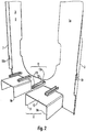
- FIG. 3 shows partially schematically a detail of the arrangement of FIG. 1 .
- the second pallet 25 is also stored on the holding element 5.
- the holding element 5 is connected to the first end of the support spar 3. From the support member 3, the stabilizing strut 18 extends to the adjacent support spar, not shown.
- a support projection 17a extend from mutually substantially perpendicularly arranged boundary edges of the first support surface 17.
- the support projection 17a counteracts an undesired displacement of the second pallet 25 with respect to the first support surface 17. Otherwise, the comments on the previous figures apply.
- Fig. 4 shows partially schematically another arrangement with a preferred embodiment of the transport auxiliary device and a pallet.
- the transport auxiliary device of FIG. 1 is stored on the loading floor 21 of the pallet 20 for storage or return transport.
- the first support device 2 is deposited on the pallet 20, the second support device 2a is placed on the first support device 2.
- the two support devices 2, 2a are detachably connected mechanically to the pallet 20, preferably by means of at least one of the connecting struts 33 formed with a belt.
- the two support devices 2, 2a extend only insignificantly beyond boundary edges of the loading floor 21. In this state, the transport auxiliary device 1 can be stored with little effort and / or moved between two storage locations. Otherwise, the comments on the previous figures apply.
- Fig. 5 shows partially schematically different views of a preferred embodiment of the auxiliary transport device.
- Stiffening ribs 7, 7a at least in sections extend from opposite boundary edges of the metallic base plate 6 of the support device 2 for stiffening the base plate 6 and the support device 2.
- the stiffening ribs 7, 7a have mechanical connecting means 19 correspondingly Figures 2 on.
- the connecting member 4 is provided with first connecting protrusions 8 and second connecting protrusions 11 corresponding to FIG FIG. 2 educated.
- First ends of the substantially parallel aligned support rails 3, 3a have holding elements 5, 5a substantially corresponding to those of FIG. 1 on.
- a stabilizing strut 18 connects the support struts 3, 3a and a further stabilizing strut 18a connects the holding elements 5, 5a, in particular for the mechanical stabilization of the support means 2.
- the connecting strut 33 formed with a pull rod serves for releasable mechanical connection with the stabilizing struts 18a. Otherwise, the comments on the previous figures apply.
- Fig. 6 shows partially schematically different views of a preferred embodiment of the auxiliary transport device. The following are the differences from the execution of the FIG. 5 explained.
- the stiffening rib 7 extends over the entire length of the support spar 3a and forms a leg of the support spar 3a.
- the stiffening rib 7 has a mechanical Connecting means 19 according to the FIG. 2 on.
- the support spar 3a has a plurality of recesses 15, 15a for releasable mechanical connection with one of the connecting struts.
- the connection strut 33 formed with a pull rod serves for releasable mechanical connection with the stabilizing struts 18a.
- Fig. 7 shows partially schematically different views of a preferred embodiment of the auxiliary transport device.
- Stiffening ribs 7, 7a at least in sections extend from opposite boundary edges of the metallic base plate 6 of the support device 2 for stiffening the base plate 6 and the support device 2.
- the stiffening ribs 7, 7a have mechanical connecting means 19 correspondingly Figures 2 on.
- the connecting member 4 is provided with first connecting protrusions 8 and second connecting protrusions 11 corresponding to FIG FIG. 2 educated.
- First ends of the substantially parallel aligned support rails 3, 3a have holding elements 5, 5a substantially corresponding to those of FIG. 1 on.
- a stabilizing strut 18 connects the support struts 3, 3a and a further stabilizing strut 18a connects the holding elements 5, 5a, in particular for the mechanical stabilization of the support means 2.
- the connecting strut 33 formed with a pull rod serves for releasable mechanical connection with the stabilizing struts 18a. Otherwise, the comments on the previous figures apply.
- Fig. 8 shows partially schematically different views of a preferred embodiment of the auxiliary transport device. The following are the differences from the execution of the FIG. 6 explained.
- the support device 2 or its support member 3a which a foot plate 14, which can support the first pallet, not shown, during transport.
- the foot plate 14, particularly preferably cohesively connected to the stiffening leg 9, in particular for improved mechanical stability of the connecting element 4.
- the trained with a pull rod connecting bar 33 serves for releasable mechanical connection with the stabilizing struts 18 a.
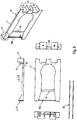
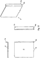
- Fig. 9 shows partially schematically different views of a base plate 6 of a preferred embodiment of the auxiliary transport device.
- the base plate 6 extend in sections stiffening ribs 7, 7a. Holding elements 5, 5a are connected to the first ends of the support bars 3, 3a.
- the connecting element is not finished yet.
- the base plate 6 has a plurality of recesses 15 for later connection to first and / or second connecting projections of the connecting element.
- the stiffening ribs 7, 7a each have mechanical connecting means 19, 19a for detachable connection to one of the connecting struts 33.
- One of the mechanical connecting means is formed with a, in particular from the stiffening rib 7a cut, pin 19, which extends during transport substantially in the vertical direction and which is in particular connected to a formed as a loop 34 stop means of the connecting strut 33a.
- this loop 34 is preferably to be solved.
- Another mechanical connection means is formed with two projections 19a, 19b, cut in particular from the reinforcing rib 7a, which extend in a substantially vertical direction during transport.
- One of these projections 19a points downwards during transport, the other of these projections 19b upwards, and a gap remains between the free ends of these projections 19a, 19b.
- This gap can be designed as a loop 34 stop means of Connecting strut 33 is guided and slipped over both projections 19a, 19b.
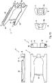
- Fig. 10 shows partially schematically different views of a first connection projection 8 of a preferred embodiment of the transport auxiliary device.
- the first connecting projection 8 is provided for later cohesive connection with the base plate.
- the first connection projection 8 has a second leg 10, which is supported by two stiffening legs 9, 9a.
- the first connection projection 8 is made with a metal plate.
- the stiffening legs 9, 9a are produced by bending the metal plate.
- Connecting portions 40, 40a, 40b extend from the legs 9, 10. These connecting portions are for mechanical connection with recesses 15 of the base plate 6 of the FIG. 9 intended.
- Fig. 11 shows partially schematically different views of a second connection projection 11 of a preferred embodiment of the transport auxiliary device.
- the second connection projection 11 is for later cohesive connection with the base plate 6, for example, the FIG. 9 intended.
- the second connection projection 11 has a second leg 13, which is supported by two stiffening legs 12, 12a.
- the second connection projection 11 is made with a metal plate.
- the stiffening legs 12, 12a are produced by bending the metal plate.
- Connecting portions 40, 40a extend from the stiffening legs 12, 12a. These connection sections are for mechanical connection with recesses 15 of the base plate 6, for example the FIG. 9 intended.
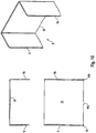
- Fig. 12 shows partially schematically different views of a holding element 5 of a preferred embodiment of the auxiliary transport device.
- the holding element 5 is provided for later cohesive connection with one of the support members.
- the holding element 5 is formed with an angled metal plate. Along a boundary edge of the support surface 17, the support projection 17a extends. Extending from the holding element 5 are connecting sections 40, 40a, which for mechanical connection with recesses 15 of the base plate 6, for example, the FIG. 9 are provided.
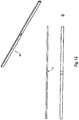
- Fig. 13 shows partially schematically different views of a stabilizing strut 18 of a preferred embodiment of the auxiliary transport device.
- the stabilizing strut 18 is formed with a metal profile and is provided, later with the base plate 6, for example, the FIG. 9 or with the two support beams of the same support means, in particular cohesively, to be connected.
- the stabilizing strut 18 has a recess 15, which is provided for releasable mechanical connection with a connecting strut of the same transport auxiliary device.
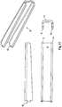
- Fig. 14 shows partially schematically different views of a connecting strut 33 of a preferred embodiment of the transport auxiliary device.
- the connecting strut 33 is formed with a metal profile and is provided to be releasably mechanically connected to one of the stabilizing struts of the two support devices later. At their ends, the connecting strut 33 respectively recesses on which to engage in recesses of the stabilizing strut of FIG. 13 are provided.
- Fig. 15 shows partially schematically different views of one of the support means of a preferred embodiment of the auxiliary transport device.
- the auxiliary transport device has at least one of the connecting struts 33, wherein a first end of the connecting strut 33 is pivotally connected to one of the holding elements 16 of the first support means 2 and has an axis 19b.
- the holding element 16 has a receiving element for the axis 19b of the connecting strut 33.
- a second end of the connecting strut 33, comprising a hook 19, is releasably mechanically connectable to a holding element of the second supporting device, not shown.
- the first support means 2 also has a holding element 5, which serves the releasable mechanical connection with a connecting strut of the second support means, not shown.
- the holding element 5 in a section on a through hole 19a, wherein the portion is made by deformation of the remaining holding element 5, whereby at least the thickness of the connecting strut of the second support means, not shown, can be compensated.
- the connecting strut 33 can be reversibly moved from a rest position, in which the connecting strut extends substantially along one of the support struts of the first support means 2, into a use position be transferred, in which the mechanical connection means is releasably connected to the first holding element of the second support means and the connecting strut extends substantially horizontally.
- the support bars 3, 3a are connected to each other by a stabilizing strut 18.
- the holding element 5 and the holding element 16 are connected to different support bars 3, 3a.
- the base plate 6 is connected to first connecting protrusions 8, 8 a and to second connecting protrusions 11.
- Fig. 16 shows partially schematically a base plate of the support means of Fig. 15 ,
- This base plate 3 is made by means of cutting and forming and is prepared for connection with holding elements and connecting projections.
- the base plate is formed with aluminum.
- the stiffening rib is produced by means of forming.
- Fig. 17 shows partially schematically a holding element 16 of the support means of Fig. 15 which extends from the holding element of Fig. 12 especially distinguished by a recess for one of the connecting struts.
- Fig. 18 shows partially schematically another holding element 5 of the support means of Fig. 15 , which is retaining element of Fig. 12 especially differs by a portion with the through hole 19a.
- the plane of the through hole 19 a is spaced from the plane of the first support surface 17.
- Fig. 19 shows partially schematically a connecting strut 33 of the preferred embodiment of the transport auxiliary device of Fig. 15 ,
- the first end of the connecting strut 33 has a Through hole for an axis on and the second end of the hook 19th
- Fig. 20 shows partially schematically the transport auxiliary device of Fig. 15 with two pallets 20, 25.
- the first connecting strut 33 is pivotally connected to the first support means 2 and the second connecting strut 33a is pivotally connected to the second support means 2a.
- the connecting struts 33, 33a are not yet converted into their use positions.
- the support devices 2, 2 a are already connected by means of their connecting elements or first connecting projections 8 to the lower pallet 20 and the second pallet 25 is placed on the holding elements 5, 16.
- the cohesion of the two support means during transport or in the use position can be improved.
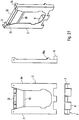
- Fig. 21 shows partially schematically one of the support means 2 of another preferred embodiment of the auxiliary transport device.
- At least two of the support bars 3, 3a of the support device 2 are connected to one another by means of the functional strut 32, in particular materially connected, preferably wherein one, two or more of the connecting struts, not shown, are mechanically connectable to the functional strut 32.
- the functional strut is formed with a U-profile, which are arranged in the use position below the holding elements 5, 16. Within the U-profile belt reels or straps can be attached.
- the support beams 3, 3 a are connected to one another by means of one of the stabilizing struts 18.
- the Supporting device 2 has two first connecting projections 8, 8a and mechanical connecting means 19a for connection struts, not shown.
- Fig. 22 shows partially schematically a base plate 6 of the support means of Fig. 21 with stiffening ribs 7 and mechanical connection means 19a for connection struts, not shown.
- Fig. 23 shows partially schematically a functional strut 32 of the support means of Fig. 21 , with a substantially U-shaped cross-section.
- the functional strut 32 is prepared for mechanical connection with two straps.
- Fig. 24 shows partially schematically the transport auxiliary device of Fig. 21 with two pallets 20, 25.
- the support means 2, 2a are connected by means of their connecting elements or first connecting projections 8 but already with the lower pallet 20 and the second pallet 25 is placed on the holding elements 5, 16.
- the respectively formed as a tension belt connecting struts 33, 33a are transferred to their use positions, ie the first ends of the connecting struts 33, 33a are releasably mechanically connected to the other support means 2, 2a.
- the first ends of the connecting struts 33, 33 a each have a mechanical connecting means designed as a loop 34.
- the tension straps are stretched and urge the support means 2, 2a to each other.
- the cohesion of the two support means during transport or in the use position can be improved.
Landscapes
- Engineering & Computer Science (AREA)
- Mechanical Engineering (AREA)
- Pallets (AREA)
Claims (9)
- Dispositif auxiliaire de transport (1) pour au moins une première et une deuxième palette (20, 25), les palettes (20, 25) présentant un fond de chargement (21) orienté essentiellement horizontalement dans la position d'utilisation lors du transport, avec un premier dispositif de support (2) et avec un deuxième dispositif de support (2a) pour supporter au moins l'une des palettes (20, 25), les deux dispositifs de support (2, 2a) présentant :- au moins un élément de raccordement (4) pour le raccordement mécanique du dispositif de support (2, 2a) à la première palette (20), l'élément de raccordement (4) présentant deux premières saillies de raccordement (8) qui peuvent s'engager mécaniquement dans différents évidements pour des moyens de levage (22) de la première palette (20) et qui sont espacées l'une de l'autre à cet effet, chaque première saillie de raccordement (8) présentant au moins une branche de rigidification (9) et une deuxième branche (10) coudée par rapport à la branche de rigidification,- au moins deux longerons de support (3, 3a) qui s'étendent essentiellement dans la direction verticale dans la position d'utilisation lors du transport, à chaque fois avec une première extrémité qui forme, dans la position d'utilisation, l'extrémité supérieure du longeron de support respectif lors du transport,- au moins deux éléments de retenue (5, 16) qui sont raccordés à chaque fois à la première extrémité de l'un des deux longerons de support (3, 3a), chacun des éléments de retenue (5, 16) étant prévu pour retenir ou supporter la deuxième de ces palettes (25) à distance verticale de la première palette (20) dans la position d'utilisation lors du transport des deux palettes (20, 25),caractérisé en ce que
le dispositif de support (2, 2a) est réalisé avec une plaque de base (6) depuis laquelle deux nervures de rigidification (7) s'étendent depuis des extrémités opposées de la plaque de base et sont orientées essentiellement parallèlement, les premières saillies de raccordement (8) de l'élément de raccordement (4) s'étendant essentiellement à angle droit et, dans la position d'utilisation, essentiellement horizontalement à partir de la plaque de base (6) du dispositif de support (2, 2a). - Dispositif auxiliaire de transport (1) selon la revendication 1, caractérisé par une deuxième saillie de raccordement (11) du même élément de raccordement (4), espacée verticalement dans la position d'utilisation lors du transport par rapport à une première saillie de raccordement (8), une portion de la première palette (20) pouvant être reçue mécaniquement entre les deux saillies de raccordement (8, 11).
- Dispositif auxiliaire de transport (1) selon l'une quelconque des revendications précédentes, caractérisé en ce qu'au moins l'un des éléments de retenue (5, 16) présente une première surface de support (17) orientée essentiellement horizontalement pendant le transport pour supporter la deuxième palette (25) et au moins une saillie de support (17a) coudée par rapport à la première surface de support (17).
- Dispositif auxiliaire de transport (1) selon l'une quelconque des revendications précédentes, caractérisé en ce que les deux longerons de support (3, 3a) d'au moins l'un des dispositifs de support (2, 2a) sont raccordés l'un à l'autre au moyen d'une première entretoise de stabilisation (18) .
- Dispositif auxiliaire de transport (1) selon l'une quelconque des revendications précédentes, caractérisé par au moins une entretoise de raccordement (33) pour le raccordement mécanique amovible du premier dispositif de support (2) au deuxième dispositif de support (2a).
- Dispositif auxiliaire de transport (1) selon la revendication 5, caractérisé en ce que l'une des nervures de rigidification (7) de la plaque de base (6) présente un moyen de raccordement mécanique (19) pour le raccordement mécanique à l'une des entretoises de raccordement (33).
- Dispositif auxiliaire de transport (1) selon la revendication 5 ou 6, caractérisé en ce qu'une première extrémité de l'entretoise de raccordement (33) est raccordée de manière articulée à l'un des éléments de retenue (5, 16) du premier dispositif de support (2),
une deuxième extrémité de l'entretoise de raccordement (33), opposée à la première extrémité, présentant un moyen de raccordement mécanique (19), peut être raccordée mécaniquement de manière amovible à un premier élément de retenue (5, 16) du deuxième dispositif de support (2a),
le premier élément de retenue (5, 16) du deuxième dispositif de support (2a) présente un moyen de raccordement mécanique (19a) complémentaire du moyen de raccordement mécanique (19) de l'entretoise de raccordement (33). - Dispositif auxiliaire de transport (1) selon l'une quelconque des revendications précédentes, caractérisé en ce que les deux longerons de support (3, 3a) d'au moins l'un des dispositifs de support (2, 2a) sont raccordés l'un à l'autre au moyen d'une entretoise fonctionnelle (32), de préférence au moins l'une des entretoises de raccordement (33) selon l'une quelconque des revendications 5 à 7 peut être raccordée à l'entretoise fonctionnelle (32).
- Agencement comprenant un dispositif auxiliaire de transport (1) selon l'une quelconque des revendications précédentes et comprenant une ou deux palettes (20, 25), le premier dispositif de support (2) et le deuxième dispositif de support (2a) étant à chaque fois raccordés mécaniquement à la première palette (20) au moyen de leur élément de raccordement (4).
Applications Claiming Priority (3)
| Application Number | Priority Date | Filing Date | Title |
|---|---|---|---|
| DE102014007905.8A DE102014007905A1 (de) | 2014-05-28 | 2014-05-28 | Transporthilfsvorrichtung und Verfahren zu deren Anwendung |
| DE102014014667.7A DE102014014667A1 (de) | 2014-10-02 | 2014-10-02 | Transporthilfsvorrichtung und Verfahren zu deren Anwendung |
| PCT/EP2015/057099 WO2015180870A1 (fr) | 2014-05-28 | 2015-03-31 | Dispositif d'aide au transport et son procédé d'utilisation |
Publications (2)
| Publication Number | Publication Date |
|---|---|
| EP3148890A1 EP3148890A1 (fr) | 2017-04-05 |
| EP3148890B1 true EP3148890B1 (fr) | 2019-08-21 |
Family
ID=52774260
Family Applications (1)
| Application Number | Title | Priority Date | Filing Date |
|---|---|---|---|
| EP15712959.4A Active EP3148890B1 (fr) | 2014-05-28 | 2015-03-31 | Dispositif auxiliaire de transport pour palettes |
Country Status (9)
| Country | Link |
|---|---|
| US (1) | US10029820B2 (fr) |
| EP (1) | EP3148890B1 (fr) |
| JP (1) | JP6805131B2 (fr) |
| CN (1) | CN106536359B (fr) |
| AU (1) | AU2015266347B2 (fr) |
| BR (1) | BR112016027622B1 (fr) |
| CA (1) | CA2950332C (fr) |
| ES (1) | ES2757955T3 (fr) |
| WO (1) | WO2015180870A1 (fr) |
Families Citing this family (8)
| Publication number | Priority date | Publication date | Assignee | Title |
|---|---|---|---|---|
| CN106536359B (zh) | 2014-05-28 | 2019-10-18 | 灵智投资股份有限公司 | 输送辅助装置及其使用方法 |
| DE102016104861A1 (de) * | 2016-03-16 | 2017-09-21 | Sprick Gmbh Bielefelder Papier- Und Wellpappenwerke & Co. | Kippschutzvorrichtung |
| UA127988C2 (uk) * | 2016-11-27 | 2024-03-06 | Спейсінвайдер Апс | Система полиць для піддонів та спосіб зберігання товарів на системі полиць для піддонів |
| US10954033B2 (en) * | 2017-09-29 | 2021-03-23 | Mtd Products Inc | Foldable crate for a lawn maintenance vehicle |
| GB201806264D0 (en) * | 2018-04-17 | 2018-05-30 | Chep Technology Pty Ltd | Pallet |
| USD904477S1 (en) * | 2019-03-26 | 2020-12-08 | Rapyuta Robotics Co., Ltd. | Roll pallet opener |
| US10934053B1 (en) * | 2019-12-09 | 2021-03-02 | FreightWeb Services, Inc. | Adjustable pallet rack |
| WO2021119509A1 (fr) * | 2019-12-13 | 2021-06-17 | Tarpey James | Insert de plateforme de distribution de charge |
Citations (12)
| Publication number | Priority date | Publication date | Assignee | Title |
|---|---|---|---|---|
| US2926792A (en) | 1958-10-14 | 1960-03-01 | Hatfield Ind Inc | Stacking rack for pallets |
| GB1137244A (en) | 1967-09-11 | 1968-12-18 | Erik Nobel | A framework for use with a load-bearing plate |
| DE7732613U1 (de) | 1977-10-22 | 1978-03-09 | Aspa Foerdergeraete | Flachpaletten-Stapelbuegel |
| DE102005051347B3 (de) | 2005-10-25 | 2007-02-08 | Siegel Gmbh & Co.Kg | Palettenbügel für eine Euro-Palette |
| EP2357142A1 (fr) | 2010-02-11 | 2011-08-17 | Number 1 Logistics Group S.p.A. | Structure en forme de cage pour le transport de marchandises |
| DE102010000535A1 (de) | 2010-02-24 | 2011-08-25 | Pötzsch, Holger, 64297 | Vorrichtung zur Ladungssicherung von Transportgütern auf Paletten |
| DE102011008019A1 (de) * | 2011-01-05 | 2012-07-05 | @Vance B.V. | Transporthilfsvorrichtung und Verfahren zu ihrer Anwendung |
| EP2733085A1 (fr) | 2012-11-20 | 2014-05-21 | David Wright | Cadre pour palettes |
| WO2015055206A1 (fr) | 2013-10-14 | 2015-04-23 | Freebird & Sunshine | Système d'étagère à palettes et procédé de stockage de marchandises sur un système d'étagère à palettes |
| DE102014007905A1 (de) | 2014-05-28 | 2015-12-03 | @Vance B.V. | Transporthilfsvorrichtung und Verfahren zu deren Anwendung |
| WO2015180870A1 (fr) | 2014-05-28 | 2015-12-03 | @Vance B.V. | Dispositif d'aide au transport et son procédé d'utilisation |
| DE102014014667A1 (de) | 2014-10-02 | 2016-04-07 | @Vance B.V. | Transporthilfsvorrichtung und Verfahren zu deren Anwendung |
Family Cites Families (23)
| Publication number | Priority date | Publication date | Assignee | Title |
|---|---|---|---|---|
| US2728544A (en) * | 1950-07-28 | 1955-12-27 | Republic Steel Corp | Stacking boxes |
| US2941772A (en) * | 1958-08-25 | 1960-06-21 | Lynn W Thayer | Shelving support for pallet frames |
| US3091195A (en) * | 1961-04-07 | 1963-05-28 | Ralph W Kenyon | Pallet superstructure |
| US3327654A (en) * | 1966-03-10 | 1967-06-27 | Collapsible Pallet Co | Collapsible cargo pallet with removable top |
| JPS5553472Y2 (fr) * | 1975-05-21 | 1980-12-11 | ||
| US3998169A (en) * | 1975-09-04 | 1976-12-21 | Bliss & Laughlin Ind., Inc. | Knock-down pallet stacker |
| US4165806A (en) * | 1976-07-26 | 1979-08-28 | Bud Antle, Inc. | Palletizing system for produce cartons and the like |
| US4491076A (en) * | 1981-07-29 | 1985-01-01 | Formall Syn-Trac Systems, Inc. | Stacking cube construction |
| US4703702A (en) * | 1986-10-16 | 1987-11-03 | Ready Metal Manufacturing Company | Multi-level pallet assembly |
| FR2673600B1 (fr) * | 1991-03-08 | 1993-05-28 | Maillard Gilbert | Pied, notamment pour embase de conteneur, du type palette, pouvant etre empile. |
| NL9300280A (nl) * | 1993-02-12 | 1994-09-01 | Mattheus Antoon Johan Pronk | Laadbord-afstandhoudersamenstel. |
| JPH0858789A (ja) * | 1994-08-18 | 1996-03-05 | Wako Paretsuto:Kk | ポストパレット |
| USD376889S (en) * | 1995-02-02 | 1996-12-24 | Ohio Rack, Inc. | Design for material handling support rack |
| US5979338A (en) * | 1997-05-23 | 1999-11-09 | Salmanson; Jeffrey | Modular low cost pallet and shelf assembly |
| US5918551A (en) * | 1998-02-04 | 1999-07-06 | Liu; Ching Rong | Trestle stage |
| GB2336147A (en) * | 1998-04-08 | 1999-10-13 | Deryn Richard Warren Best | A support frame suitable for use with a non-rigid container |
| GB2354225B (en) * | 1999-07-07 | 2001-08-08 | Ricoh Kk | Commodity carrying and storing apparatus |
| US6202569B1 (en) * | 1999-08-03 | 2001-03-20 | Bailey Nurseries, Inc. | Stackable pallet system |
| US6405880B1 (en) * | 2001-07-02 | 2002-06-18 | Rtc Industries, Inc. | Rack merchandising system |
| US7802526B2 (en) * | 2007-03-05 | 2010-09-28 | Paccar Inc | Modular and customizable returnable rack system |
| JP3155486U (ja) * | 2009-09-07 | 2009-11-19 | 富山工業株式会社 | パレットサポートの組立具 |
| GB201008131D0 (en) * | 2010-05-14 | 2010-06-30 | Transport pallet | |
| CN103237733B (zh) * | 2010-11-12 | 2015-12-02 | 艾特万斯私人有限公司 | 运输辅助设备及其使用方法 |
-
2015
- 2015-03-31 CN CN201580038547.3A patent/CN106536359B/zh not_active Expired - Fee Related
- 2015-03-31 US US15/314,402 patent/US10029820B2/en active Active
- 2015-03-31 WO PCT/EP2015/057099 patent/WO2015180870A1/fr not_active Ceased
- 2015-03-31 BR BR112016027622-1A patent/BR112016027622B1/pt active IP Right Grant
- 2015-03-31 ES ES15712959T patent/ES2757955T3/es active Active
- 2015-03-31 JP JP2017514790A patent/JP6805131B2/ja active Active
- 2015-03-31 CA CA2950332A patent/CA2950332C/fr active Active
- 2015-03-31 EP EP15712959.4A patent/EP3148890B1/fr active Active
- 2015-03-31 AU AU2015266347A patent/AU2015266347B2/en active Active
Patent Citations (12)
| Publication number | Priority date | Publication date | Assignee | Title |
|---|---|---|---|---|
| US2926792A (en) | 1958-10-14 | 1960-03-01 | Hatfield Ind Inc | Stacking rack for pallets |
| GB1137244A (en) | 1967-09-11 | 1968-12-18 | Erik Nobel | A framework for use with a load-bearing plate |
| DE7732613U1 (de) | 1977-10-22 | 1978-03-09 | Aspa Foerdergeraete | Flachpaletten-Stapelbuegel |
| DE102005051347B3 (de) | 2005-10-25 | 2007-02-08 | Siegel Gmbh & Co.Kg | Palettenbügel für eine Euro-Palette |
| EP2357142A1 (fr) | 2010-02-11 | 2011-08-17 | Number 1 Logistics Group S.p.A. | Structure en forme de cage pour le transport de marchandises |
| DE102010000535A1 (de) | 2010-02-24 | 2011-08-25 | Pötzsch, Holger, 64297 | Vorrichtung zur Ladungssicherung von Transportgütern auf Paletten |
| DE102011008019A1 (de) * | 2011-01-05 | 2012-07-05 | @Vance B.V. | Transporthilfsvorrichtung und Verfahren zu ihrer Anwendung |
| EP2733085A1 (fr) | 2012-11-20 | 2014-05-21 | David Wright | Cadre pour palettes |
| WO2015055206A1 (fr) | 2013-10-14 | 2015-04-23 | Freebird & Sunshine | Système d'étagère à palettes et procédé de stockage de marchandises sur un système d'étagère à palettes |
| DE102014007905A1 (de) | 2014-05-28 | 2015-12-03 | @Vance B.V. | Transporthilfsvorrichtung und Verfahren zu deren Anwendung |
| WO2015180870A1 (fr) | 2014-05-28 | 2015-12-03 | @Vance B.V. | Dispositif d'aide au transport et son procédé d'utilisation |
| DE102014014667A1 (de) | 2014-10-02 | 2016-04-07 | @Vance B.V. | Transporthilfsvorrichtung und Verfahren zu deren Anwendung |
Non-Patent Citations (1)
| Title |
|---|
| ANONYMOUS: "Spaceinvaders", 17 May 2014 (2014-05-17), XP055722900, Retrieved from the Internet <URL:http://web.archive.org/web/20140517105736/http://fands.dk/#spaceinvader> |
Also Published As
| Publication number | Publication date |
|---|---|
| BR112016027622A2 (fr) | 2017-08-15 |
| CN106536359A (zh) | 2017-03-22 |
| BR112016027622B1 (pt) | 2022-05-24 |
| CN106536359B (zh) | 2019-10-18 |
| EP3148890A1 (fr) | 2017-04-05 |
| ES2757955T3 (es) | 2020-04-30 |
| CA2950332C (fr) | 2023-03-21 |
| JP2017516724A (ja) | 2017-06-22 |
| CA2950332A1 (fr) | 2015-12-03 |
| AU2015266347A1 (en) | 2016-12-22 |
| JP6805131B2 (ja) | 2020-12-23 |
| WO2015180870A1 (fr) | 2015-12-03 |
| AU2015266347B2 (en) | 2020-01-30 |
| US10029820B2 (en) | 2018-07-24 |
| US20170190464A1 (en) | 2017-07-06 |
Similar Documents
| Publication | Publication Date | Title |
|---|---|---|
| EP3148890A1 (fr) | Dispositif d'aide au transport et son procédé d'utilisation | |
| EP2637942B1 (fr) | Dispositif auxiliaire de transport notamment pour palettes | |
| EP2088094B1 (fr) | Unité de chargement pour le transport intermodal et le transfert de marchandises | |
| WO2010146089A1 (fr) | Système de transport | |
| DE102008052238B4 (de) | Einrichtung zum Transportieren von im Wesentlichen langgestreckten runden Gegenständen | |
| DE202015106050U1 (de) | Entfernbare Rahmensysteme für den Fahrzeugtransport | |
| DE102010000535A1 (de) | Vorrichtung zur Ladungssicherung von Transportgütern auf Paletten | |
| EP3429934B1 (fr) | Dispositif de support pour une palette | |
| EP2590867B1 (fr) | Dispositif de transport | |
| EP3552992B1 (fr) | Plateforme de transport | |
| DE10312638A1 (de) | Verfahren und Vorrichtung zur Ladungssicherung | |
| DE102014014667A1 (de) | Transporthilfsvorrichtung und Verfahren zu deren Anwendung | |
| DE19517925C1 (de) | Gestell zum Lagern und/oder Transportieren von Glasscheibenpaketen | |
| DE102014007905A1 (de) | Transporthilfsvorrichtung und Verfahren zu deren Anwendung | |
| DE19706493A1 (de) | LKW-Aufbau | |
| DE102016109634B4 (de) | Ladungssicherungshaken zum Verbinden eines Haltemittels mit einerLadungssicherungsschiene sowie Ladungssicherungsmittel und Aufbau einesNutzfahrzeugs jeweils mit dem Ladungssicherungshaken | |
| EP3800159B1 (fr) | Combinaison chariot de manutention et aide au transport | |
| DE3535940C2 (fr) | ||
| DE69703647T2 (de) | Leichter und zerlegbarer Transportbehälter | |
| DE202021102146U1 (de) | Transportsicherung | |
| DE3220859C2 (de) | Langgut-Container | |
| DE102016115786B4 (de) | Ladungssicherungseinrichtung für Nutzfahrzeuge | |
| DE102011008019A1 (de) | Transporthilfsvorrichtung und Verfahren zu ihrer Anwendung | |
| DE9401032U1 (de) | Tragevorrichtung für Ladepaletten | |
| DE2902940A1 (de) | Vorrichtung zum buendeln von materialrollen |
Legal Events
| Date | Code | Title | Description |
|---|---|---|---|
| STAA | Information on the status of an ep patent application or granted ep patent |
Free format text: STATUS: THE INTERNATIONAL PUBLICATION HAS BEEN MADE |
|
| PUAI | Public reference made under article 153(3) epc to a published international application that has entered the european phase |
Free format text: ORIGINAL CODE: 0009012 |
|
| STAA | Information on the status of an ep patent application or granted ep patent |
Free format text: STATUS: REQUEST FOR EXAMINATION WAS MADE |
|
| 17P | Request for examination filed |
Effective date: 20161201 |
|
| AK | Designated contracting states |
Kind code of ref document: A1 Designated state(s): AL AT BE BG CH CY CZ DE DK EE ES FI FR GB GR HR HU IE IS IT LI LT LU LV MC MK MT NL NO PL PT RO RS SE SI SK SM TR |
|
| AX | Request for extension of the european patent |
Extension state: BA ME |
|
| DAV | Request for validation of the european patent (deleted) | ||
| DAX | Request for extension of the european patent (deleted) | ||
| STAA | Information on the status of an ep patent application or granted ep patent |
Free format text: STATUS: EXAMINATION IS IN PROGRESS |
|
| 17Q | First examination report despatched |
Effective date: 20180122 |
|
| GRAP | Despatch of communication of intention to grant a patent |
Free format text: ORIGINAL CODE: EPIDOSNIGR1 |
|
| STAA | Information on the status of an ep patent application or granted ep patent |
Free format text: STATUS: GRANT OF PATENT IS INTENDED |
|
| INTG | Intention to grant announced |
Effective date: 20190219 |
|
| GRAS | Grant fee paid |
Free format text: ORIGINAL CODE: EPIDOSNIGR3 |
|
| GRAJ | Information related to disapproval of communication of intention to grant by the applicant or resumption of examination proceedings by the epo deleted |
Free format text: ORIGINAL CODE: EPIDOSDIGR1 |
|
| GRAL | Information related to payment of fee for publishing/printing deleted |
Free format text: ORIGINAL CODE: EPIDOSDIGR3 |
|
| STAA | Information on the status of an ep patent application or granted ep patent |
Free format text: STATUS: EXAMINATION IS IN PROGRESS |
|
| GRAJ | Information related to disapproval of communication of intention to grant by the applicant or resumption of examination proceedings by the epo deleted |
Free format text: ORIGINAL CODE: EPIDOSDIGR1 |
|
| GRAL | Information related to payment of fee for publishing/printing deleted |
Free format text: ORIGINAL CODE: EPIDOSDIGR3 |
|
| GRAR | Information related to intention to grant a patent recorded |
Free format text: ORIGINAL CODE: EPIDOSNIGR71 |
|
| STAA | Information on the status of an ep patent application or granted ep patent |
Free format text: STATUS: GRANT OF PATENT IS INTENDED |
|
| INTC | Intention to grant announced (deleted) | ||
| GRAA | (expected) grant |
Free format text: ORIGINAL CODE: 0009210 |
|
| STAA | Information on the status of an ep patent application or granted ep patent |
Free format text: STATUS: THE PATENT HAS BEEN GRANTED |
|
| INTC | Intention to grant announced (deleted) | ||
| AK | Designated contracting states |
Kind code of ref document: B1 Designated state(s): AL AT BE BG CH CY CZ DE DK EE ES FI FR GB GR HR HU IE IS IT LI LT LU LV MC MK MT NL NO PL PT RO RS SE SI SK SM TR |
|
| INTG | Intention to grant announced |
Effective date: 20190716 |
|
| REG | Reference to a national code |
Ref country code: GB Ref legal event code: FG4D Free format text: NOT ENGLISH |
|
| REG | Reference to a national code |
Ref country code: CH Ref legal event code: EP |
|
| REG | Reference to a national code |
Ref country code: DE Ref legal event code: R096 Ref document number: 502015010065 Country of ref document: DE |
|
| REG | Reference to a national code |
Ref country code: AT Ref legal event code: REF Ref document number: 1169483 Country of ref document: AT Kind code of ref document: T Effective date: 20190915 |
|
| REG | Reference to a national code |
Ref country code: IE Ref legal event code: FG4D Free format text: LANGUAGE OF EP DOCUMENT: GERMAN |
|
| REG | Reference to a national code |
Ref country code: SE Ref legal event code: TRGR |
|
| REG | Reference to a national code |
Ref country code: NL Ref legal event code: FP |
|
| REG | Reference to a national code |
Ref country code: LT Ref legal event code: MG4D |
|
| REG | Reference to a national code |
Ref country code: NO Ref legal event code: T2 Effective date: 20190821 |
|
| PG25 | Lapsed in a contracting state [announced via postgrant information from national office to epo] |
Ref country code: BG Free format text: LAPSE BECAUSE OF FAILURE TO SUBMIT A TRANSLATION OF THE DESCRIPTION OR TO PAY THE FEE WITHIN THE PRESCRIBED TIME-LIMIT Effective date: 20191121 Ref country code: HR Free format text: LAPSE BECAUSE OF FAILURE TO SUBMIT A TRANSLATION OF THE DESCRIPTION OR TO PAY THE FEE WITHIN THE PRESCRIBED TIME-LIMIT Effective date: 20190821 Ref country code: PT Free format text: LAPSE BECAUSE OF FAILURE TO SUBMIT A TRANSLATION OF THE DESCRIPTION OR TO PAY THE FEE WITHIN THE PRESCRIBED TIME-LIMIT Effective date: 20191223 Ref country code: LT Free format text: LAPSE BECAUSE OF FAILURE TO SUBMIT A TRANSLATION OF THE DESCRIPTION OR TO PAY THE FEE WITHIN THE PRESCRIBED TIME-LIMIT Effective date: 20190821 |
|
| PG25 | Lapsed in a contracting state [announced via postgrant information from national office to epo] |
Ref country code: GR Free format text: LAPSE BECAUSE OF FAILURE TO SUBMIT A TRANSLATION OF THE DESCRIPTION OR TO PAY THE FEE WITHIN THE PRESCRIBED TIME-LIMIT Effective date: 20191122 Ref country code: IS Free format text: LAPSE BECAUSE OF FAILURE TO SUBMIT A TRANSLATION OF THE DESCRIPTION OR TO PAY THE FEE WITHIN THE PRESCRIBED TIME-LIMIT Effective date: 20191221 Ref country code: RS Free format text: LAPSE BECAUSE OF FAILURE TO SUBMIT A TRANSLATION OF THE DESCRIPTION OR TO PAY THE FEE WITHIN THE PRESCRIBED TIME-LIMIT Effective date: 20190821 Ref country code: AL Free format text: LAPSE BECAUSE OF FAILURE TO SUBMIT A TRANSLATION OF THE DESCRIPTION OR TO PAY THE FEE WITHIN THE PRESCRIBED TIME-LIMIT Effective date: 20190821 Ref country code: LV Free format text: LAPSE BECAUSE OF FAILURE TO SUBMIT A TRANSLATION OF THE DESCRIPTION OR TO PAY THE FEE WITHIN THE PRESCRIBED TIME-LIMIT Effective date: 20190821 |
|
| REG | Reference to a national code |
Ref country code: ES Ref legal event code: FG2A Ref document number: 2757955 Country of ref document: ES Kind code of ref document: T3 Effective date: 20200430 |
|
| PG25 | Lapsed in a contracting state [announced via postgrant information from national office to epo] |
Ref country code: DK Free format text: LAPSE BECAUSE OF FAILURE TO SUBMIT A TRANSLATION OF THE DESCRIPTION OR TO PAY THE FEE WITHIN THE PRESCRIBED TIME-LIMIT Effective date: 20190821 Ref country code: EE Free format text: LAPSE BECAUSE OF FAILURE TO SUBMIT A TRANSLATION OF THE DESCRIPTION OR TO PAY THE FEE WITHIN THE PRESCRIBED TIME-LIMIT Effective date: 20190821 Ref country code: RO Free format text: LAPSE BECAUSE OF FAILURE TO SUBMIT A TRANSLATION OF THE DESCRIPTION OR TO PAY THE FEE WITHIN THE PRESCRIBED TIME-LIMIT Effective date: 20190821 Ref country code: PL Free format text: LAPSE BECAUSE OF FAILURE TO SUBMIT A TRANSLATION OF THE DESCRIPTION OR TO PAY THE FEE WITHIN THE PRESCRIBED TIME-LIMIT Effective date: 20190821 |
|
| REG | Reference to a national code |
Ref country code: DE Ref legal event code: R026 Ref document number: 502015010065 Country of ref document: DE |
|
| PG25 | Lapsed in a contracting state [announced via postgrant information from national office to epo] |
Ref country code: IS Free format text: LAPSE BECAUSE OF FAILURE TO SUBMIT A TRANSLATION OF THE DESCRIPTION OR TO PAY THE FEE WITHIN THE PRESCRIBED TIME-LIMIT Effective date: 20200224 Ref country code: SK Free format text: LAPSE BECAUSE OF FAILURE TO SUBMIT A TRANSLATION OF THE DESCRIPTION OR TO PAY THE FEE WITHIN THE PRESCRIBED TIME-LIMIT Effective date: 20190821 Ref country code: CZ Free format text: LAPSE BECAUSE OF FAILURE TO SUBMIT A TRANSLATION OF THE DESCRIPTION OR TO PAY THE FEE WITHIN THE PRESCRIBED TIME-LIMIT Effective date: 20190821 Ref country code: SM Free format text: LAPSE BECAUSE OF FAILURE TO SUBMIT A TRANSLATION OF THE DESCRIPTION OR TO PAY THE FEE WITHIN THE PRESCRIBED TIME-LIMIT Effective date: 20190821 |
|
| PLBI | Opposition filed |
Free format text: ORIGINAL CODE: 0009260 |
|
| PLAX | Notice of opposition and request to file observation + time limit sent |
Free format text: ORIGINAL CODE: EPIDOSNOBS2 |
|
| REG | Reference to a national code |
Ref country code: FI Ref legal event code: MDE Opponent name: SPACEINVADER APS |
|
| 26 | Opposition filed |
Opponent name: SPACEINVADER APS Effective date: 20200520 |
|
| PG2D | Information on lapse in contracting state deleted |
Ref country code: IS |
|
| PG25 | Lapsed in a contracting state [announced via postgrant information from national office to epo] |
Ref country code: SI Free format text: LAPSE BECAUSE OF FAILURE TO SUBMIT A TRANSLATION OF THE DESCRIPTION OR TO PAY THE FEE WITHIN THE PRESCRIBED TIME-LIMIT Effective date: 20190821 |
|
| PLAK | Information related to reply of patent proprietor to notice(s) of opposition modified |
Free format text: ORIGINAL CODE: EPIDOSCOBS3 |
|
| PLBB | Reply of patent proprietor to notice(s) of opposition received |
Free format text: ORIGINAL CODE: EPIDOSNOBS3 |
|
| PG25 | Lapsed in a contracting state [announced via postgrant information from national office to epo] |
Ref country code: MC Free format text: LAPSE BECAUSE OF FAILURE TO SUBMIT A TRANSLATION OF THE DESCRIPTION OR TO PAY THE FEE WITHIN THE PRESCRIBED TIME-LIMIT Effective date: 20190821 |
|
| REG | Reference to a national code |
Ref country code: CH Ref legal event code: PL |
|
| PG25 | Lapsed in a contracting state [announced via postgrant information from national office to epo] |
Ref country code: LU Free format text: LAPSE BECAUSE OF NON-PAYMENT OF DUE FEES Effective date: 20200331 |
|
| PG25 | Lapsed in a contracting state [announced via postgrant information from national office to epo] |
Ref country code: LI Free format text: LAPSE BECAUSE OF NON-PAYMENT OF DUE FEES Effective date: 20200331 Ref country code: CH Free format text: LAPSE BECAUSE OF NON-PAYMENT OF DUE FEES Effective date: 20200331 Ref country code: IE Free format text: LAPSE BECAUSE OF NON-PAYMENT OF DUE FEES Effective date: 20200331 |
|
| PLAB | Opposition data, opponent's data or that of the opponent's representative modified |
Free format text: ORIGINAL CODE: 0009299OPPO |
|
| R26 | Opposition filed (corrected) |
Opponent name: SPACEINVADER APS Effective date: 20200520 |
|
| REG | Reference to a national code |
Ref country code: AT Ref legal event code: MM01 Ref document number: 1169483 Country of ref document: AT Kind code of ref document: T Effective date: 20200331 |
|
| PG25 | Lapsed in a contracting state [announced via postgrant information from national office to epo] |
Ref country code: AT Free format text: LAPSE BECAUSE OF NON-PAYMENT OF DUE FEES Effective date: 20200331 |
|
| PG25 | Lapsed in a contracting state [announced via postgrant information from national office to epo] |
Ref country code: MT Free format text: LAPSE BECAUSE OF FAILURE TO SUBMIT A TRANSLATION OF THE DESCRIPTION OR TO PAY THE FEE WITHIN THE PRESCRIBED TIME-LIMIT Effective date: 20190821 Ref country code: CY Free format text: LAPSE BECAUSE OF FAILURE TO SUBMIT A TRANSLATION OF THE DESCRIPTION OR TO PAY THE FEE WITHIN THE PRESCRIBED TIME-LIMIT Effective date: 20190821 |
|
| PLCK | Communication despatched that opposition was rejected |
Free format text: ORIGINAL CODE: EPIDOSNREJ1 |
|
| PG25 | Lapsed in a contracting state [announced via postgrant information from national office to epo] |
Ref country code: MK Free format text: LAPSE BECAUSE OF FAILURE TO SUBMIT A TRANSLATION OF THE DESCRIPTION OR TO PAY THE FEE WITHIN THE PRESCRIBED TIME-LIMIT Effective date: 20190821 |
|
| APBM | Appeal reference recorded |
Free format text: ORIGINAL CODE: EPIDOSNREFNO |
|
| APBP | Date of receipt of notice of appeal recorded |
Free format text: ORIGINAL CODE: EPIDOSNNOA2O |
|
| APAH | Appeal reference modified |
Free format text: ORIGINAL CODE: EPIDOSCREFNO |
|
| APBQ | Date of receipt of statement of grounds of appeal recorded |
Free format text: ORIGINAL CODE: EPIDOSNNOA3O |
|
| P01 | Opt-out of the competence of the unified patent court (upc) registered |
Effective date: 20230601 |
|
| REG | Reference to a national code |
Ref country code: DE Ref legal event code: R100 Ref document number: 502015010065 Country of ref document: DE |
|
| APBU | Appeal procedure closed |
Free format text: ORIGINAL CODE: EPIDOSNNOA9O |
|
| PGFP | Annual fee paid to national office [announced via postgrant information from national office to epo] |
Ref country code: FI Payment date: 20240320 Year of fee payment: 10 Ref country code: GB Payment date: 20240320 Year of fee payment: 10 |
|
| PLBN | Opposition rejected |
Free format text: ORIGINAL CODE: 0009273 |
|
| STAA | Information on the status of an ep patent application or granted ep patent |
Free format text: STATUS: OPPOSITION REJECTED |
|
| PGFP | Annual fee paid to national office [announced via postgrant information from national office to epo] |
Ref country code: SE Payment date: 20240320 Year of fee payment: 10 Ref country code: NO Payment date: 20240322 Year of fee payment: 10 Ref country code: IT Payment date: 20240329 Year of fee payment: 10 |
|
| 27O | Opposition rejected |
Effective date: 20240416 |
|
| REG | Reference to a national code |
Ref country code: FI Ref legal event code: FGE |
|
| PGFP | Annual fee paid to national office [announced via postgrant information from national office to epo] |
Ref country code: DE Payment date: 20250331 Year of fee payment: 11 |
|
| PGFP | Annual fee paid to national office [announced via postgrant information from national office to epo] |
Ref country code: NL Payment date: 20250319 Year of fee payment: 11 |
|
| PGFP | Annual fee paid to national office [announced via postgrant information from national office to epo] |
Ref country code: BE Payment date: 20250319 Year of fee payment: 11 |
|
| PGFP | Annual fee paid to national office [announced via postgrant information from national office to epo] |
Ref country code: FR Payment date: 20250325 Year of fee payment: 11 |
|
| PGFP | Annual fee paid to national office [announced via postgrant information from national office to epo] |
Ref country code: TR Payment date: 20250325 Year of fee payment: 11 |
|
| PGFP | Annual fee paid to national office [announced via postgrant information from national office to epo] |
Ref country code: ES Payment date: 20250429 Year of fee payment: 11 |
|
| PG25 | Lapsed in a contracting state [announced via postgrant information from national office to epo] |
Ref country code: FI Free format text: LAPSE BECAUSE OF NON-PAYMENT OF DUE FEES Effective date: 20250331 |
|
| GBPC | Gb: european patent ceased through non-payment of renewal fee |
Effective date: 20250331 |
|
| REG | Reference to a national code |
Ref country code: SE Ref legal event code: EUG |
|
| PG25 | Lapsed in a contracting state [announced via postgrant information from national office to epo] |
Ref country code: GB Free format text: LAPSE BECAUSE OF NON-PAYMENT OF DUE FEES Effective date: 20250331 |
|
| PG25 | Lapsed in a contracting state [announced via postgrant information from national office to epo] |
Ref country code: NO Free format text: LAPSE BECAUSE OF NON-PAYMENT OF DUE FEES Effective date: 20250331 |
|
| PG25 | Lapsed in a contracting state [announced via postgrant information from national office to epo] |
Ref country code: IT Free format text: LAPSE BECAUSE OF NON-PAYMENT OF DUE FEES Effective date: 20250331 |
|
| PG25 | Lapsed in a contracting state [announced via postgrant information from national office to epo] |
Ref country code: SE Free format text: LAPSE BECAUSE OF NON-PAYMENT OF DUE FEES Effective date: 20250401 |