EP3148901B1 - Système de contenants de transport et procédé - Google Patents
Système de contenants de transport et procédé Download PDFInfo
- Publication number
- EP3148901B1 EP3148901B1 EP15717805.4A EP15717805A EP3148901B1 EP 3148901 B1 EP3148901 B1 EP 3148901B1 EP 15717805 A EP15717805 A EP 15717805A EP 3148901 B1 EP3148901 B1 EP 3148901B1
- Authority
- EP
- European Patent Office
- Prior art keywords
- container
- wall elements
- version
- elements
- wall
- Prior art date
- Legal status (The legal status is an assumption and is not a legal conclusion. Google has not performed a legal analysis and makes no representation as to the accuracy of the status listed.)
- Active
Links
Images


Classifications
-
- B—PERFORMING OPERATIONS; TRANSPORTING
- B65—CONVEYING; PACKING; STORING; HANDLING THIN OR FILAMENTARY MATERIAL
- B65D—CONTAINERS FOR STORAGE OR TRANSPORT OF ARTICLES OR MATERIALS, e.g. BAGS, BARRELS, BOTTLES, BOXES, CANS, CARTONS, CRATES, DRUMS, JARS, TANKS, HOPPERS, FORWARDING CONTAINERS; ACCESSORIES, CLOSURES, OR FITTINGS THEREFOR; PACKAGING ELEMENTS; PACKAGES
- B65D81/00—Containers, packaging elements, or packages, for contents presenting particular transport or storage problems, or adapted to be used for non-packaging purposes after removal of contents
- B65D81/38—Containers, packaging elements, or packages, for contents presenting particular transport or storage problems, or adapted to be used for non-packaging purposes after removal of contents with thermal insulation
- B65D81/3813—Containers, packaging elements, or packages, for contents presenting particular transport or storage problems, or adapted to be used for non-packaging purposes after removal of contents with thermal insulation rigid container being in the form of a box, tray or like container
- B65D81/3823—Containers, packaging elements, or packages, for contents presenting particular transport or storage problems, or adapted to be used for non-packaging purposes after removal of contents with thermal insulation rigid container being in the form of a box, tray or like container formed of different materials, e.g. laminated or foam filling between walls
-
- B—PERFORMING OPERATIONS; TRANSPORTING
- B65—CONVEYING; PACKING; STORING; HANDLING THIN OR FILAMENTARY MATERIAL
- B65D—CONTAINERS FOR STORAGE OR TRANSPORT OF ARTICLES OR MATERIALS, e.g. BAGS, BARRELS, BOTTLES, BOXES, CANS, CARTONS, CRATES, DRUMS, JARS, TANKS, HOPPERS, FORWARDING CONTAINERS; ACCESSORIES, CLOSURES, OR FITTINGS THEREFOR; PACKAGING ELEMENTS; PACKAGES
- B65D43/00—Lids or covers for rigid or semi-rigid containers
- B65D43/02—Removable lids or covers
-
- B—PERFORMING OPERATIONS; TRANSPORTING
- B65—CONVEYING; PACKING; STORING; HANDLING THIN OR FILAMENTARY MATERIAL
- B65D—CONTAINERS FOR STORAGE OR TRANSPORT OF ARTICLES OR MATERIALS, e.g. BAGS, BARRELS, BOTTLES, BOXES, CANS, CARTONS, CRATES, DRUMS, JARS, TANKS, HOPPERS, FORWARDING CONTAINERS; ACCESSORIES, CLOSURES, OR FITTINGS THEREFOR; PACKAGING ELEMENTS; PACKAGES
- B65D81/00—Containers, packaging elements, or packages, for contents presenting particular transport or storage problems, or adapted to be used for non-packaging purposes after removal of contents
- B65D81/38—Containers, packaging elements, or packages, for contents presenting particular transport or storage problems, or adapted to be used for non-packaging purposes after removal of contents with thermal insulation
- B65D81/3825—Containers, packaging elements, or packages, for contents presenting particular transport or storage problems, or adapted to be used for non-packaging purposes after removal of contents with thermal insulation rigid container being in the form of a box, tray or like container with one or more containers located inside the external container
-
- F—MECHANICAL ENGINEERING; LIGHTING; HEATING; WEAPONS; BLASTING
- F25—REFRIGERATION OR COOLING; COMBINED HEATING AND REFRIGERATION SYSTEMS; HEAT PUMP SYSTEMS; MANUFACTURE OR STORAGE OF ICE; LIQUEFACTION SOLIDIFICATION OF GASES
- F25D—REFRIGERATORS; COLD ROOMS; ICE-BOXES; COOLING OR FREEZING APPARATUS NOT OTHERWISE PROVIDED FOR
- F25D3/00—Devices using other cold materials; Devices using cold-storage bodies
- F25D3/02—Devices using other cold materials; Devices using cold-storage bodies using ice, e.g. ice-boxes
- F25D3/06—Movable containers
- F25D3/08—Movable containers portable, i.e. adapted to be carried personally
-
- F—MECHANICAL ENGINEERING; LIGHTING; HEATING; WEAPONS; BLASTING
- F25—REFRIGERATION OR COOLING; COMBINED HEATING AND REFRIGERATION SYSTEMS; HEAT PUMP SYSTEMS; MANUFACTURE OR STORAGE OF ICE; LIQUEFACTION SOLIDIFICATION OF GASES
- F25D—REFRIGERATORS; COLD ROOMS; ICE-BOXES; COOLING OR FREEZING APPARATUS NOT OTHERWISE PROVIDED FOR
- F25D2201/00—Insulation
- F25D2201/10—Insulation with respect to heat
- F25D2201/14—Insulation with respect to heat using subatmospheric pressure
-
- F—MECHANICAL ENGINEERING; LIGHTING; HEATING; WEAPONS; BLASTING
- F25—REFRIGERATION OR COOLING; COMBINED HEATING AND REFRIGERATION SYSTEMS; HEAT PUMP SYSTEMS; MANUFACTURE OR STORAGE OF ICE; LIQUEFACTION SOLIDIFICATION OF GASES
- F25D—REFRIGERATORS; COLD ROOMS; ICE-BOXES; COOLING OR FREEZING APPARATUS NOT OTHERWISE PROVIDED FOR
- F25D2303/00—Details of devices using other cold materials; Details of devices using cold-storage bodies
- F25D2303/08—Devices using cold storage material, i.e. ice or other freezable liquid
- F25D2303/082—Devices using cold storage material, i.e. ice or other freezable liquid disposed in a cold storage element not forming part of a container for products to be cooled, e.g. ice pack or gel accumulator
- F25D2303/0822—Details of the element
- F25D2303/08222—Shape of the element
-
- F—MECHANICAL ENGINEERING; LIGHTING; HEATING; WEAPONS; BLASTING
- F25—REFRIGERATION OR COOLING; COMBINED HEATING AND REFRIGERATION SYSTEMS; HEAT PUMP SYSTEMS; MANUFACTURE OR STORAGE OF ICE; LIQUEFACTION SOLIDIFICATION OF GASES
- F25D—REFRIGERATORS; COLD ROOMS; ICE-BOXES; COOLING OR FREEZING APPARATUS NOT OTHERWISE PROVIDED FOR
- F25D2303/00—Details of devices using other cold materials; Details of devices using cold-storage bodies
- F25D2303/08—Devices using cold storage material, i.e. ice or other freezable liquid
- F25D2303/084—Position of the cold storage material in relationship to a product to be cooled
- F25D2303/0843—Position of the cold storage material in relationship to a product to be cooled on the side of the product
-
- F—MECHANICAL ENGINEERING; LIGHTING; HEATING; WEAPONS; BLASTING
- F25—REFRIGERATION OR COOLING; COMBINED HEATING AND REFRIGERATION SYSTEMS; HEAT PUMP SYSTEMS; MANUFACTURE OR STORAGE OF ICE; LIQUEFACTION SOLIDIFICATION OF GASES
- F25D—REFRIGERATORS; COLD ROOMS; ICE-BOXES; COOLING OR FREEZING APPARATUS NOT OTHERWISE PROVIDED FOR
- F25D2303/00—Details of devices using other cold materials; Details of devices using cold-storage bodies
- F25D2303/08—Devices using cold storage material, i.e. ice or other freezable liquid
- F25D2303/084—Position of the cold storage material in relationship to a product to be cooled
- F25D2303/0844—Position of the cold storage material in relationship to a product to be cooled above the product
-
- F—MECHANICAL ENGINEERING; LIGHTING; HEATING; WEAPONS; BLASTING
- F25—REFRIGERATION OR COOLING; COMBINED HEATING AND REFRIGERATION SYSTEMS; HEAT PUMP SYSTEMS; MANUFACTURE OR STORAGE OF ICE; LIQUEFACTION SOLIDIFICATION OF GASES
- F25D—REFRIGERATORS; COLD ROOMS; ICE-BOXES; COOLING OR FREEZING APPARATUS NOT OTHERWISE PROVIDED FOR
- F25D2303/00—Details of devices using other cold materials; Details of devices using cold-storage bodies
- F25D2303/08—Devices using cold storage material, i.e. ice or other freezable liquid
- F25D2303/084—Position of the cold storage material in relationship to a product to be cooled
- F25D2303/0845—Position of the cold storage material in relationship to a product to be cooled below the product
Definitions
- the invention relates to a transport container system having the features of the preamble of claim 1 and to a method for equipping a container of a transport container system having the features of the preamble of claim 11.
- a transport container system whose basic component is first a container having a bottom, a jacket and a lid.
- a container may be cubic or cuboidal.
- the mantle has longitudinal walls and transverse walls.
- the container may also be cylindrical or tubular.
- the mantle has a cylindrical shape.
- the jacket can be made in one piece with the ground. It is essential that at least one cover is present, so that the interior of the container is accessible from the outside. Cover in this sense may also be a laterally arranged door when it is a cup-like, closed by a door from the top container instead of a trough-like, closed by a lid from above container.
- the transport container system includes at least one container and a suitable number of inner wall elements. To a transport container system but can also include several containers with a correspondingly higher number of inner wall elements. For multiple containers, the containers may have the same size / shape or different sizes / shapes.
- a transport container system with a corresponding thermally insulated container is from the WO 2004/104498 A2 known.
- the container is designed here like a cabinet with an outer container made of sheet metal or plate-like plastic material and an inner container fitted in the outer container.
- the inner container is formed by inner container wall elements, which are designed as thermal insulation elements. These inner container wall elements are here throughout vacuum insulation panels. These are currently the most efficient thermal insulation elements.
- the transport container known from the previously described prior art has a plurality of insertion guides in the interior. Leave in the slot guides to use a suitable for the purpose number of cooling batteries or latent heat storage elements. Also in this respect, reference may be made to the disclosure of this citation.
- a latent heat storage element is based on the use of latent heat storage material.
- a latent heat storage material has the advantage that it can store relatively large amounts of heat with it in a small temperature interval. Since the phase transition occurs at a substantially constant temperature over a certain period of time, it is possible to compensate for temperature fluctuations and to avoid temperature peaks.
- Latent heat storage materials are known in various forms. These materials are also called PCM materials (phase change material) from English terminology.
- a latent heat storage element according to the present invention is a latent heat storage material in a closed, possibly also provided with a pressure equalization valve enclosure. This is also referred to as a macroencapsulated PCM material.
- the wrapping is often made of plastic.
- Such latent heat storage elements can be considered individually or as a plurality of, for example, built in a corresponding container latent heat storage elements.
- Latent heat storage elements of the type in question are now available for a wealth of target temperatures, in particular by the applicant (Prospectus "va-Q-tec Packaging Portfolio, January 2011”). There you will find latent heat storage elements for target temperatures of 37 ° C, 22 ° C, 4 ° C, 0 ° C, -19 ° C, -21 ° C and -32 ° C. Other suppliers have comparable latent heat storage elements in the sales program, in part also for other target temperatures.
- Latent heat storage elements of the type in question are used in the present field of application in thermally insulated containers, especially for transport purposes.
- this applies to the transport of temperature-sensitive goods such as pharmaceuticals, biotechnological products, testing equipment or samples for and from clinical studies, transplant goods or stored blood.
- the optimum transport and storage temperature to be observed is 2 ° C to 8 ° C.
- the products are only stable in a very narrow temperature range. These products must therefore be transported and stored in this temperature range mandatory.
- such products, which are very sensitive to the transport temperature must never freeze under any circumstances. Temperatures below 0 ° C must then be safely avoided.
- thermally insulated container WO 2004/104498 A2
- the design of the inner container and the arrangement of the individual inner container wall elements is fixed from the outset. All inner container wall elements are designed the same, there are preferably vacuum insulation panels. If and as far as a single inner container wall element can be removed and used, it is replaced by an identical inner container wall element. This happens when damaged, for example, a vacuum insulation panel.
- Variable is in the known transport container system, the number of latent heat storage elements in the insertion guides, which are arranged inside the inner container on the inner surfaces. By a larger or smaller number of latent heat storage elements in the transport container can be considered different thermal requirements for the cargo.
- the prior art described above relates to a transport container for temperature-sensitive cargo, but no transport container system in the strict sense.
- a transport container system of the type in question is known from the starting point for the teaching of the present invention forming DE 203 01 839 U1 ,
- the local transport container system has a container with an outer container made of heat-insulating material and an inner container, which consists entirely of vacuum insulation panels.
- an inner container which consists entirely of vacuum insulation panels.
- six plate-shaped vacuum insulation panels are needed there (on the bottom, on the four side walls and on the lid) to form the inner container.
- each inner wall element has predetermined, matching the associated inner surface of the container dimensions.
- the idea of the known state of the art is then to design only the inner wall elements on the two largest surfaces as vacuum insulation panels, the inner wall elements on the four narrower side surfaces on the other hand with thermal insulation elements of classic design, for example, from conventional foam plastic equip.
- thermal insulation elements of classic design for example, from conventional foam plastic equip.
- the flexibility of the arrangement is improved in this prior art in that instead of running as a vacuum insulation panels inner container wall elements also designed as cooling batteries or holding batteries inner container wall elements can be used with the same dimensions.
- transport containers of the type in question must be designed according to the specific application for different thermal requirements.
- the desired service life ie the time over which the target temperature is maintained in the interior of the transport container intended for receiving the transported goods (holding period)
- an adaptable transport container system according to the preamble of claim 1 is with EP 2 221 569 A1 disclosed.
- the teaching is therefore based on the problem, the transport container system of the type in question in such a way and further, that it can be more flexible than before adapted to different thermal requirements.
- the teaching is also based on the problem of specifying a correspondingly improved method for equipping a container of such a transport container system.
- the present invention solves the above-identified problem in a transport container system having the features of the preamble of claim 1 by the features of the characterizing portion of claim 1.
- Preferred embodiments and further developments are the subject of the subclaims related to the device.
- the basic idea of the transport container system according to the invention consists first of all at least in some of the inner wall elements vorzuhalten several versions that have at least substantially the same dimensions, but differ significantly in thermal terms. Due to the appropriate selection of the inner wall element to be used on the intended inner surface from a supply of inner wall elements of different designs, a transport container perfectly adapted to the specific requirements can be realized.
- According to the invention can therefore select the individual inner wall elements in the container so that the simple and secure packing scheme remains unchanged in the container, but compared to the thermally optimal equipment of the container some or more inner wall elements against inner wall elements of the same dimensions, but thermally less demanding and thus cheaper Execution be replaced.
- the invention provides that an inner wall element, which is provided in at least two embodiments, in a first embodiment, a latent heat storage element or other heat storage element or a Vakuumisolationspaneel and in a second embodiment, a placeholder element with lower thermal insulation than a vacuum insulation panel.
- an inner wall element namely as a latent heat storage element or another heat storage element in a first embodiment, as a vacuum insulation panel in a second embodiment and as a placeholder element with a lower thermal insulation effect in a third embodiment.
- a latent heat storage element of the type described in detail initially represents the most efficient form of heat storage element.
- other heat storage elements are used, for example, based on sensitive heat heat storage element such as a cold pack or even a heat storage block high mass (for example, stone or chamotte).
- the system can be further modified for the placeholder element by holding up placeholder elements with a lower thermal insulation effect than a vacuum insulation panel in turn in different versions with different thermal insulation effect for selection.
- an inner wall element in one of the available embodiments can be used at the intended for the affected inner wall element position in the container. So you can largely modify the equipment of the container in thermal terms. It is possible to exchange interior wall elements with different thermal effects, for example heat insulation on the one hand and heat storage on the other, or one can use designs of different quality and different price within a selection of different interior wall elements of the same thermal effect. The overall performance of the transport container in the appropriately chosen within the system design can be optimally adjusted.
- EPS expanded polystyrene
- EPP expanded Polypropylene
- PU polyurethane
- the previously described container in the thermally optimal design can be modified in the direction of influencing the internal temperature thereby that some of the inner wall elements in the embodiment as vacuum insulation panels replaced by inner wall elements in the design as latent heat storage elements or, at lower requirements than other heat storage elements.
- the transport container system in a particularly preferred embodiment to work in multiple layers, namely with an outer container and an inner container fitted in the outer container.
- the inner container in turn consists of individual, individually removable and usable inner container wall elements and that the inner container wall elements are designed as thermal insulation elements.
- the inner wall elements in the container are in this embodiment with outer container and inner container on the inner surfaces of the inner container.
- the inner container with its inner container wall elements represents the heat insulation, while the inner wall elements in the container can all be latent heat storage elements, or also partially latent heat storage elements, partially vacuum insulation panels or placeholder elements.
- all interior wall elements are vacuum insulation panels or placeholder elements if one wishes to dispense entirely with a latent heat storage element.
- the inner wall elements and / or the inner container wall elements of different types have at least approximately matching properties in mechanical terms.
- the inserted element also substantially fulfills the mechanical functions, for example the function of stiffening the container or the function of a support or fixation of other elements.
- the inner wall elements and / or the inner container wall elements plate-shaped and, preferably, at the mutually facing edges to each other are bevelled appropriately. In the latter and preferred case, one has the least possible gaps between the inner wall elements or the inner container wall elements.
- Embodiments of other containers find exemplary examples in the prior art explained in the introduction ( DE 203 01 839 U1 ). This disclosure content may be expressly referred to here.
- the serving as placeholder elements inner wall elements and / or inner container wall elements may also have recesses for receiving corresponding functional elements. This is difficult with vacuum insulation panels, but can be well realized in other, consisting of other materials placeholder elements. So you can, for example, there again provide recesses for attaching latent heat storage elements or cooling batteries, but also for data carriers, documents or other measuring devices.
- the invention also provides a method for equipping a container of a transport container system with the features of the preamble of claim 11, which is defined in more detail by the features of the characterizing part of claim 11.
- preferred embodiments and further developments of the method according to the invention are the subject matter of claims 12 to 15.
- a suitable selection of inner wall elements in the container can be made with the method.
- the simple and secure packing scheme in the container remains unchanged.
- the container can be optimized for the full range of possible equipment. Depending on the requirement profile for the material to be transported, it is possible to thermally equip more or less demanding and therefore higher or lower in price.
- the inner wall elements are provided in three versions, namely a first embodiment as latent heat storage element or as another heat storage element, in a second embodiment as a vacuum insulation panel and in a third embodiment as a heat-insulating placeholder element with a lower thermal insulation effect than a vacuum insulation panel or that in step 1.
- the inner wall elements are provided in four embodiments, namely a first embodiment as latent heat storage element, in a second embodiment as another heat storage element, in a third embodiment as a vacuum insulation panel and in a fourth embodiment as a heat-insulating placeholder element with a lower thermal insulation effect than a vacuum insulation panel.
- inner container wall elements designed as thermal insulation elements are provided in method step 1, wherein, preferably, the inner container wall elements are provided in at least two embodiments, namely at least one embodiment as a vacuum insulation panel and in a second embodiment as heat-insulating Placeholder element with a lower thermal insulation effect than a vacuum insulation panel.
- the placeholder elements themselves can work in the inventive method with different designs.
- the inner wall elements or inner container wall elements designed as heat-insulating placeholder elements are in turn provided in different embodiments, namely a design of plastic, in particular of foamed plastic, and / or a design of paper / cardboard and / or one Made of wood, in particular of wood products, and / or a version made of lightweight construction material.
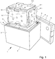
- the in Fig. 1 illustrated transport container 1 of a transport container system initially has a bottom 2, a jacket 3 and a cover 4.
- the container 1 is cuboid shaped.
- the jacket 3 has two longitudinal sides and two transverse sides.
- other container shapes are known, for example, with a cylindrical shell. On the remarks may be referred.
- Fig. 1 illustrated embodiment 5 inner wall elements 6 are arranged in the container 1 on the inner side of the wall, which can be removed from the container 1 and inserted into the container 1.
- Each inner wall element 6 has predetermined dimensions matching the associated inner surface 5 of the container 1.
- Fig. 1 illustrated embodiment is a particular embodiment in such a way that the container 1 itself again has an outer container 7 and a fitted in the outer container 7 inner container 8.
- the construction of the container 1 in the illustrated embodiment corresponds to the construction provided in the container of the prior art forming the starting point.
- the invention is also concerned with a transport container system with at least one container 1, which consists only of the outer container 7, that is, does not have a fitted inner container 8.
- the outer container 7 is, for example, a container of comparatively thin-walled foamed plastic material (e.g., an EPP molding).
- the container 1 is like a trough with top lid 4 executed.
- the bottom 2 with the jacket 3 is made in one piece.
- the container 1 thus shown may be provided externally again with a cardboard packaging.
- the outer carton of the particular embodiment designed in this way may carry an advertising inscription or instructions for use.
- an inner wall for example, an inner box or an inliner, which defines the interior of the container 1. Again, this is just a preferred embodiment.
- FIG. 1 illustrated and preferred embodiment shows a total of six plate-shaped inner wall elements 6.
- Each of the inner wall elements 6 is designed here as a latent heat storage element. It is therefore inner wall elements 6 in a first embodiment 6.1 as latent heat storage elements.
- Fig. 2 shows the embodiment Fig. 1 modified.
- some inner wall elements 6.1 in the first embodiment are designed as latent heat storage elements by inner wall elements 6.3 in one embodiment as placeholder elements with a lower thermal insulation effect than a vacuum insulation panel.
- each an inner wall element 6.1, designed as latent heat storage element, left and right on the long sides each have an inner wall element 6.1, designed as latent heat storage element, and the front side an inner wall element 6.3, designed as a placeholder element.
- the latter end wall-side inner wall elements 6.3 of the third embodiment replace the inner wall element 6.1 Fig. 1 , This is possible because the exchanged within the transport container system according to the invention inner wall elements 6 have at least substantially the same dimensions.
- the long sides of the shell 3 associated inner wall elements are also 6.1 replaced in the embodiment as latent heat storage elements by inner wall elements 6.2 in the embodiment as a vacuum insulation panels.
- the heat storage elements have also been replaced by thermal insulation elements, but by the most efficient form of thermal insulation elements, namely by inner wall elements 6.2 in the second embodiment as a vacuum insulation panels.
- the thermal insulation over the large areas is thus particularly efficient, can be used with the inner wall elements 6.3 in the third embodiment as placeholder elements with lower thermal insulation effect on the smaller faces, without affecting the overall performance of the concrete so designed transport container too strong.
- the container 1 of outer container 7 and inner container 8 is constructed.
- the inner container 8 in turn consists of individually removable inner container wall elements 9.
- the inner container wall elements 9 are here consistently designed as thermal insulation elements.
- all inner container wall elements 9 are designed consistently, namely as inner container vacuum insulation panels.
- a modification namely, provide that there are several versions, at least one embodiment as mecanical-Vakuumisolationspaneel and another embodiment at least substantially the same dimension as a placeholder element with lower thermal insulation than a vacuum insulation.
- a placeholder element with a lower thermal insulation effect than a vacuum insulation panel can be in the inner wall elements 6 as well as in the inner container wall elements 9 introduce more levels, so for example placeholder elements different thermal insulation effect. This can for example be based on the fact that placeholder elements made of different materials (well-foamed plastic, wood, paper / cardboard) are optionally used.
- the inner wall elements 6 and / or the inner container wall elements 9 of different embodiments have at least approximately matching properties in mechanical terms.
- the inner container wall elements 9 are plate-shaped. They are designed as vacuum insulation panels smooth plate-shaped, so not bevelled at the edges. They are rather blunt abutting installed in the outer container 7.
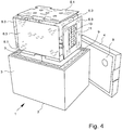
- FIG. 4 illustrated, further modified embodiment makes it clear that it is further possible according to a preferred teaching that at least one of the placeholder elements designed as inner wall elements 6.3 and / or inner container wall elements 9 has at least one recess 10 for receiving an otherwise functional element 11.
- the functional elements 11, which are indicated here, are water-based cooling batteries which have a different target temperature than the latent heat storage elements, which are positioned as inner wall elements 6.1 on the bottom 2 and the lid 4 of the container 1 in the concrete embodiment. This makes it possible to create special thermal boundary conditions in the interior of the container 1 for the transported goods located there.
- the transport container system according to the invention can be modified, for example, as follows:
- all inner container wall elements 9 are used in the embodiment as vacuum insulation panels.
- All six inner wall elements 6 are inner wall elements 6.1 in the form of latent heat storage elements.
- two of the six latent heat storage elements are replaced, so that four inner wall elements 6.1 are provided in the form of latent heat storage elements and two inner wall elements 6.2 in the form of vacuum insulation panels or two dimensionally similar inner wall elements 6.3 are provided in the form of placeholder elements with lower thermal insulation effect as a vacuum insulation panel (see Fig. 2 ).
- inner container wall elements 9 can make appropriate modifications and replace, for example, on the front pages, the relatively expensive vacuum insulation panels by placeholder elements with lower thermal insulation effect as a vacuum insulation panel.
- recesses 10 can be used for functional elements 11 of all kinds. It does not have to be the concrete water cooling batteries shown there.
- these inner wall elements 6.3 in the form of placeholder elements can also be designed simply as empty, possibly unilaterally open plastic sheaths. In such a plastic envelope can then be, for example, a required or appropriate document for the cargo.
Landscapes
- Engineering & Computer Science (AREA)
- Mechanical Engineering (AREA)
- Chemical & Material Sciences (AREA)
- Combustion & Propulsion (AREA)
- Physics & Mathematics (AREA)
- Thermal Sciences (AREA)
- General Engineering & Computer Science (AREA)
- Packages (AREA)
- Thermal Insulation (AREA)
Claims (15)
- Système de récipient de transport présentant au moins un récipient (1) doté d'un fond (2), d'une enveloppe (3) et d'un couvercle (4),
des éléments (6) de paroi intérieure disposés sur la surface intérieure (5) des parois du récipient (1), aptes à être retirés du récipient (1) et à être insérés dans le récipient (1),
chaque élément (6) de paroi intérieure présentant des dimensions prédéterminées et adaptées à la surface intérieure (5) associée du récipient (1),
plusieurs modes de réalisation d'au moins certains des éléments (6) de paroi intérieure et présentant essentiellement les mêmes dimensions faisant partie du système de récipient de transport,
un élément (6) de paroi intérieure pouvant être inséré dans l'un des modes de réalisation (6.1; 6.2; 6.3) sélectivement dans le récipient (1) en la position prévue pour l'élément (6) de paroi intérieure concerné, caractérisé en ce que
l'élément (6) de paroi intérieure concerné est dans un premier mode de réalisation un élément d'accumulation de chaleur latente, un autre élément d'accumulation de chaleur ou un panneau d'isolation sous vide et dans un deuxième mode de réalisation, l'élément (6) de paroi intérieure est un élément de placement dont la capacité d'isolation thermique est plus faible que celle d'un panneau d'isolation sous vide ou
en ce que dans un premier mode de réalisation, l'élément (6.1) de paroi intérieure est un élément d'accumulation de chaleur latente ou un autre élément d'accumulation de chaleur, dans un deuxième mode de réalisation, l'élément (6.2) de paroi intérieure est un panneau d'isolation sous vide et dans un troisième mode de réalisation, l'élément (6.3) de paroi intérieure est un élément de placement dont la capacité d'isolation thermique est plus faible que celle d'un panneau d'isolation sous vide. - Système de récipient de transport selon la revendication 1, caractérisé en ce que des éléments (6) de paroi intérieure sont disposés dans le récipient (1) sur toutes les surfaces intérieures (5), à l'exception éventuelle de petits interstices.
- Système de récipient de transport selon les revendications 1 ou 2, caractérisé en ce que le fond (2) et l'enveloppe (3) de récipient (1) sont reliés solidairement l'un à l'autre ou sont réalisés d'une seule pièce, le récipient (1) ouvert dans le haut pouvant être fermé par le couvercle (4).
- Système de récipient de transport selon l'une des revendications 1 à 3, caractérisé en ce que le récipient (1) présente un récipient extérieur (7) et un récipient intérieur (8) adapté dans le récipient extérieur (7) et en ce que le récipient intérieur (8) est pour sa part constitué de différents éléments (9) de paroi de récipient intérieur qui peuvent être extraits et insérés séparément.
- Système de récipient de transport selon la revendication 4, caractérisé en ce que les éléments (9) de paroi de récipient intérieur sont réalisés sous la forme d'éléments d'isolation thermique et en ce qu'au moins deux modes de réalisation d'éléments (9) de paroi de récipient intérieur sont prévus, à savoir au moins un mode de réalisation comme panneau d'isolation sous vide du récipient intérieur et un autre mode de réalisation comme élément de placement dont la capacité d'isolation thermique est plus faible que celle d'un panneau d'isolation sous vide.
- Système de récipient de transport selon l'une des revendications 1 à 5, caractérisé en ce que les éléments (6) de paroi intérieure et/ou les éléments (9) de paroi de récipient intérieur présentent différents modes de réalisation dont les propriétés mécaniques se correspondent au moins approximativement.
- Système de récipient de transport selon l'une des revendications 1 à 6, caractérisé en ce que les éléments (6) de paroi intérieure et/ou les éléments (9) de paroi de récipient intérieur sont réalisés en forme de plaques de préférence chanfreinées de manière mutuellement adaptée sur leurs bords tournés les uns vers les autres, et en particulier à un angle de 45°.
- Système de récipient de transport selon l'une des revendications 1 à 7, caractérisé en ce que les éléments (6) de paroi intérieure et/ou les éléments (9) de paroi de récipient intérieur sont réalisés sous la forme d'éléments de placement sont réalisés en matière synthétique, en particulier en matière synthétique moussée, en papier et/ou carton, en bois, en particulier en produits à base de bois, ou en matériau léger de construction.
- Système de récipient de transport selon l'une des revendications 1 à 8, caractérisé en ce qu'au moins l'un des éléments (6) de paroi intérieure et/ou des éléments (9) de paroi de récipient intérieur réalisés sous la forme d'éléments de placement présente au moins une découpe (10) qui reprend un élément fonctionnel (11) de nature quelconque.
- Système de récipient de transport selon l'une des revendications 1 à 7, caractérisé en ce qu'au moins l'un des éléments (6) de paroi intérieure et/ou des éléments (9) de paroi de récipient intérieur est constitué d'un matériau qui accumule l'humidité et/ou qui régule l'humidité ou est doté d'un tel matériau.
- Procédé d'équipement d'un récipient (1) d'un système de récipient de transport, dans lequel
le récipient (1) présente un fond (2), une enveloppe (3) et un couvercle (4),
des éléments (6) de paroi intérieure pouvant être placés sur la surface intérieure (5) des parois du récipient (1),
chaque élément (6) de paroi intérieure présentant des dimensions prédéterminées adaptées à la surface intérieure (5) associée du récipient (1),
les éléments (6) de paroi intérieure pouvant être insérés dans le récipient (1) et pouvant être extraits du récipient (1),
caractérisé par les étapes suivantes :1. préparation d'une sélection d'éléments (6) de paroi intérieure pour le récipient (1), et donc préparation d'au moins certains éléments (6) de paroi intérieure en au moins deux modes de réalisation, à savoir un premier mode de réalisation comme élément d'accumulation de chaleur latente, comme autre élément d'accumulation de chaleur ou comme panneau d'isolation sous vide et en dans un deuxième mode de réalisation comme élément de placement thermiquement isolant mais dont la capacité d'isolation thermique est inférieure à celle d'un panneau d'isolation sous vide,2. sélection de tous les éléments (6) de paroi intérieure du récipient (1) parmi les éléments (6) de paroi intérieure préparés à l'étape 1. du procédé,3. insertion des éléments (6) de paroi intérieure sélectionnés à l'étape 2. du procédé, dans le mode de réalisation particulier sélectionné, en les positions prévues dans le récipient (1). - Procédé selon la revendication 11, caractérisé en ce que lors de l'étape 1 du procédé, les éléments (6) de paroi intérieure sont préparés en trois modes de réalisation, à savoir un premier mode de réalisation comme élément d'accumulation de chaleur latente ou un autre élément d'accumulation de chaleur, dans un deuxième mode de réalisation comme panneau d'isolation sous vide et dans un troisième mode de réalisation comme élément de placement dont la capacité d'isolation thermique est plus faible que celle d'un panneau d'isolation sous vide ou
en ce qu'à l'étape 1 du procédé, les éléments (6) de paroi intérieure sont préparés en quatre modes de réalisation, à savoir un premier mode de réalisation comme élément d'accumulation de chaleur latente, un deuxième mode de réalisation comme autre élément d'accumulation de chaleur, un troisième mode de réalisation comme panneau d'isolation sous vide et un quatrième mode de réalisation comme élément de placement dont la capacité d'isolation thermique est plus faible que celle d'un panneau d'isolation sous vide. - Procédé selon les revendications 11 ou 12, caractérisé par les autres étapes qui consistent à :4. préparer une sélection d'éléments (9) de paroi de récipient intérieur pour un récipient intérieur (8) qui peut être adapté dans un récipient extérieur (7) du récipient (1),5. sélection de tous les éléments (9) de paroi de récipient intérieur pour le récipient intérieur (8) parmi les éléments (9) de paroi de récipient intérieur préparés à l'étape 4. du procédé et6. placement des éléments (9) de paroi de récipient intérieur sélectionnés dans l'étape 5 du procédé en les positions prévues dans le récipient extérieur (7).
- Procédé selon la revendication 13, caractérisé en ce que dans l'étape 1. du procédé sont préparés des éléments (9) de paroi de récipient intérieur réalisés sous la forme d'éléments d'isolation thermique, les éléments (9) de paroi de récipient intérieur étant préparés de préférence en au moins deux modes de réalisation, à savoir au moins un mode de réalisation comme panneau d'isolation sous vide et dans un deuxième mode de réalisation comme élément de placement dont la capacité d'isolation thermique est plus faible que celle d'un panneau d'isolation sous vide.
- Procédé selon l'une des revendications 11 à 14, caractérisé en ce que les éléments (6) de paroi intérieure et/ou les éléments (9) de paroi de récipient intérieur réalisés sous la forme d'éléments de placement thermiquement isolant sont pour leur part préparés en différents modes de réalisation, à savoir un mode de réalisation en matière synthétique, en particulier en matière synthétique moussée, et/ou un mode de réalisation en papier/carton, un mode de réalisation en bois, en particulier en produit à base de bois et/ou un mode de réalisation en matériau léger de construction.
Applications Claiming Priority (3)
| Application Number | Priority Date | Filing Date | Title |
|---|---|---|---|
| DE202014004395 | 2014-05-30 | ||
| DE202014004515.1U DE202014004515U1 (de) | 2014-05-30 | 2014-06-05 | Transportbehältersystem |
| PCT/EP2015/000760 WO2015180808A1 (fr) | 2014-05-30 | 2015-04-10 | Système et procédé de contenant de transport |
Publications (2)
| Publication Number | Publication Date |
|---|---|
| EP3148901A1 EP3148901A1 (fr) | 2017-04-05 |
| EP3148901B1 true EP3148901B1 (fr) | 2018-06-06 |
Family
ID=54193504
Family Applications (1)
| Application Number | Title | Priority Date | Filing Date |
|---|---|---|---|
| EP15717805.4A Active EP3148901B1 (fr) | 2014-05-30 | 2015-04-10 | Système de contenants de transport et procédé |
Country Status (7)
| Country | Link |
|---|---|
| US (1) | US10287085B2 (fr) |
| EP (1) | EP3148901B1 (fr) |
| JP (1) | JP6643257B2 (fr) |
| CN (1) | CN106458423B (fr) |
| DE (1) | DE202014004515U1 (fr) |
| SG (1) | SG11201609892RA (fr) |
| WO (1) | WO2015180808A1 (fr) |
Families Citing this family (66)
| Publication number | Priority date | Publication date | Assignee | Title |
|---|---|---|---|---|
| US9814331B2 (en) | 2010-11-02 | 2017-11-14 | Ember Technologies, Inc. | Heated or cooled dishware and drinkware |
| US11950726B2 (en) | 2010-11-02 | 2024-04-09 | Ember Technologies, Inc. | Drinkware container with active temperature control |
| US10010213B2 (en) | 2010-11-02 | 2018-07-03 | Ember Technologies, Inc. | Heated or cooled dishware and drinkware and food containers |
| GB2534910C (en) * | 2015-02-05 | 2021-10-27 | Laminar Medica Ltd | A Thermally Insulated Container and Method for Making Same |
| CN108495795B (zh) | 2015-11-25 | 2021-01-15 | 野醍冷却器有限责任公司 | 具有真空绝热面板的绝热容器和方法 |
| DE202016001097U1 (de) | 2016-01-28 | 2017-05-02 | Va-Q-Tec Ag | Transportbehältersystem |
| WO2017143540A1 (fr) * | 2016-02-24 | 2017-08-31 | 松冷(武汉)科技有限公司 | Réceptacle de transport, dispositif de transport et procédé de transport |
| US10689157B2 (en) | 2017-01-04 | 2020-06-23 | Otter Products, Llc | Food and beverage cooler assembly |
| US10843863B2 (en) | 2017-01-04 | 2020-11-24 | Otter Products, Llc | Food and beverage cooler assembly |
| USD823064S1 (en) | 2017-01-04 | 2018-07-17 | Otter Products, Llc | Cooler |
| DE102017000622B4 (de) * | 2017-01-25 | 2023-10-26 | Va-Q-Tec Ag | Verfahren zum Präparieren eines Transportbehälters |
| USD860789S1 (en) | 2017-03-06 | 2019-09-24 | Otter Products, Llc | Divider for storage container |
| USD823065S1 (en) | 2017-03-21 | 2018-07-17 | Otter Products, Llc | Cooler |
| USD823066S1 (en) | 2017-03-21 | 2018-07-17 | Otter Products, Llc | Cooler |
| DE102017003327B4 (de) * | 2017-03-30 | 2023-01-26 | Guido Becker | Quaderförmiger Kühl- und Transportbehälter |
| US10351330B2 (en) | 2017-04-11 | 2019-07-16 | Otter Products, Llc | Portable storage container |
| US10106393B1 (en) * | 2017-04-19 | 2018-10-23 | Winter Creek Designs | Beverage dispensing system |
| USD821165S1 (en) | 2017-04-21 | 2018-06-26 | Otter Products, Llc | Cupholder accessory |
| USD824730S1 (en) | 2017-04-21 | 2018-08-07 | Otter Products, Llc | Table accessory |
| US11511928B2 (en) | 2017-05-09 | 2022-11-29 | Cold Chain Technologies, Llc | Shipping system for storing and/or transporting temperature-sensitive materials |
| EP3634879B1 (fr) | 2017-05-09 | 2023-11-01 | Cold Chain Technologies, LLC | Système d'expédition pour le stockage et/ou le transport de matériaux sensibles à la température |
| USD821824S1 (en) | 2017-05-16 | 2018-07-03 | Yeti Coolers, Llc | Insulating device |
| US10443918B2 (en) | 2017-05-18 | 2019-10-15 | Otter Products, Llc | Configurable insulated storage container |
| US10906723B2 (en) | 2017-06-05 | 2021-02-02 | Otter Products, Llc | Collapsible portable storage container |
| CN107323878A (zh) * | 2017-06-29 | 2017-11-07 | 福建赛特新材股份有限公司 | 一种冷链保温箱和冷链保温箱的制造方法 |
| USD839054S1 (en) | 2017-08-17 | 2019-01-29 | Yeti Coolers, Llc | Container |
| US11072469B1 (en) | 2017-08-17 | 2021-07-27 | Yeti Coolers, Llc | Container and lid |
| USD856748S1 (en) | 2017-08-17 | 2019-08-20 | Yeti Coolers, Llc | Lid |
| USD839055S1 (en) | 2017-08-17 | 2019-01-29 | Yeti Coolers, Llc | Container |
| USD839056S1 (en) | 2017-08-17 | 2019-01-29 | Yeti Coolers, Llc | Container |
| KR20190055589A (ko) * | 2017-11-15 | 2019-05-23 | 오씨아이 주식회사 | 온도 조절 케이스 및 그것을 포함하는 온도 조절 패키지 |
| USD845717S1 (en) | 2018-01-18 | 2019-04-16 | Otter Products, Llc | Insulated container |
| USD850865S1 (en) | 2018-01-18 | 2019-06-11 | Otter Products, Llc | Insulated container |
| USD885903S1 (en) | 2018-04-11 | 2020-06-02 | Yeti Coolers, Llc | Lid |
| USD888509S1 (en) | 2018-04-11 | 2020-06-30 | Yeti Coolers, Llc | Container |
| USD888508S1 (en) | 2018-04-11 | 2020-06-30 | Yeti Coolers, Llc | Container |
| USD887793S1 (en) | 2018-04-11 | 2020-06-23 | Yeti Coolers, Llc | Container |
| USD878163S1 (en) | 2018-04-11 | 2020-03-17 | Yeti Coolers, Llc | Container |
| USD878166S1 (en) | 2018-04-11 | 2020-03-17 | Yeti Coolers, Llc | Container |
| WO2019204660A1 (fr) | 2018-04-19 | 2019-10-24 | Ember Technologies, Inc. | Réfrigérateur transportable à commande de température active |
| DE202018104807U1 (de) | 2018-08-21 | 2018-08-28 | Va-Q-Tec Ag | Vakuumgedämmter Stapelbehälter für den temperaturgeführten Transport von Nahrungsmitteln |
| US11267621B2 (en) | 2018-09-27 | 2022-03-08 | Otter Products, Llc | Storage container and floating latch |
| US11161678B2 (en) | 2018-11-27 | 2021-11-02 | Otter Products, Llc | Portable storage container |
| AU2020206753B2 (en) | 2019-01-11 | 2025-08-21 | Ember Lifesciences, Inc. | Portable cooler with active temperature control |
| USD908357S1 (en) | 2019-02-08 | 2021-01-26 | Otter Products, Llc | Container |
| USD912400S1 (en) | 2019-02-08 | 2021-03-09 | Otter Products, Llc | Container |
| US11162716B2 (en) | 2019-06-25 | 2021-11-02 | Ember Technologies, Inc. | Portable cooler |
| CA3143365A1 (fr) | 2019-06-25 | 2020-12-30 | Ember Technologies, Inc. | Refroidisseur portable |
| US11668508B2 (en) | 2019-06-25 | 2023-06-06 | Ember Technologies, Inc. | Portable cooler |
| JP7463669B2 (ja) * | 2019-07-02 | 2024-04-09 | 大日本印刷株式会社 | 真空断熱材が使用され、蓄熱材を備えた断熱容器 |
| US11377290B2 (en) | 2019-07-15 | 2022-07-05 | Otter Products, Llc | Portable insulated container |
| US11472625B2 (en) | 2019-07-23 | 2022-10-18 | Cold Chain Technologies, Llc | Method and system for maintaining temperature-sensitive materials within a desired temperature range for a period of time |
| US11242175B2 (en) | 2019-08-21 | 2022-02-08 | Otter Products, Llc | Configurable container |
| US11267637B2 (en) | 2019-08-21 | 2022-03-08 | Otter Products, Llc | Configurable container |
| EP4025522A4 (fr) | 2019-09-05 | 2023-12-27 | Cold Chain Technologies, LLC | Système d'expédition pour matériaux sensibles à la température |
| US11685588B2 (en) | 2020-03-26 | 2023-06-27 | Walmart Apollo, Llc | Tote handling for chilled or frozen goods |
| AU2021246654A1 (en) * | 2020-04-03 | 2022-10-27 | Ember Lifesciences, Inc. | Portable cooler with active temperature control |
| BE1028209B1 (fr) * | 2020-04-14 | 2021-11-16 | Exam Packaging | Conteneur pour stockage et/ou envoi thermostable de produits |
| US12378057B2 (en) | 2020-07-02 | 2025-08-05 | Cold Chain Technologies, Llc | Shipping system for storing and/or transporting temperature-sensitive materials |
| US12140367B2 (en) * | 2020-08-31 | 2024-11-12 | Keter Home And Garden Products Ltd | Cooler container |
| WO2022187699A1 (fr) | 2021-03-04 | 2022-09-09 | Cold Chain Technologies, Llc | Système d'expédition permettant de stocker et/ou de transporter des matériaux thermosensibles |
| EP4291511A4 (fr) * | 2021-03-11 | 2025-06-11 | Cryoport, Inc. | Dispositif d'expédition de type boîte-dans-boîte |
| USD996059S1 (en) | 2022-02-24 | 2023-08-22 | Otter Products, Llc | Container |
| GB2627175B (en) * | 2022-12-16 | 2026-01-28 | Oyster Thermal As | Insert for thermally insulated containers |
| WO2025074277A1 (fr) * | 2023-10-03 | 2025-04-10 | Temp Aid Corp. | Panneaux de matériau à changement de phase et récipient avec panneaux de matériau à changement de phase |
| GB202411886D0 (en) | 2024-08-12 | 2024-09-25 | Anderson Marcus Julian Peter | A cold chain shipper and temperature control system |
Family Cites Families (20)
| Publication number | Priority date | Publication date | Assignee | Title |
|---|---|---|---|---|
| US5555980A (en) * | 1994-09-23 | 1996-09-17 | Johnson's Trading Post, Inc. | Collapsible palletized container |
| US5899088A (en) * | 1998-05-14 | 1999-05-04 | Throwleigh Technologies, L.L.C. | Phase change system for temperature control |
| GB9915265D0 (en) * | 1999-07-01 | 1999-09-01 | Kryotrans Ltd | Thermally insulated container |
| US6325281B1 (en) * | 2000-03-30 | 2001-12-04 | Polyfoam Packers Corporation | Thermally insulating shipping system |
| DE10301318B4 (de) | 2003-01-15 | 2017-08-10 | Va-Q-Tec Ag | Wärmedämmbehältnis mit Vakuumdämmplatten |
| US7257963B2 (en) * | 2003-05-19 | 2007-08-21 | Minnesota Thermal Science, Llc | Thermal insert for container having a passive controlled temperature interior |
| DE10322764A1 (de) | 2003-05-19 | 2004-12-30 | Va-Q-Tec Ag | Container mit Vakuumisolation und Schmelzspeichermaterialien |
| US20100072211A1 (en) * | 2004-03-18 | 2010-03-25 | Eggs Overnight, Inc. | Reusable shipping container and method for using the same |
| US7681405B2 (en) * | 2005-04-14 | 2010-03-23 | Alton Williams | Insulated shipping container systems and methods thereof |
| US7263855B2 (en) * | 2005-06-08 | 2007-09-04 | Doubleday Acquisitions, Llc | Cargo container for transporting temperature sensitive items |
| JP2007022598A (ja) * | 2005-07-15 | 2007-02-01 | Sekisui Plastics Co Ltd | 温度検出器付き保温保冷容器 |
| US7963397B2 (en) * | 2006-02-09 | 2011-06-21 | Seagle Vance L | Modular, knock-down, light weight, thermally insulating, tamper proof shipping container and fire retardant shipping container bag |
| ATE432232T1 (de) * | 2006-04-12 | 2009-06-15 | Hoffmann La Roche | Behälter für den transport von gekühlten gütern |
| EP2142431A4 (fr) * | 2007-05-04 | 2014-06-18 | Entropy Solutions Inc | Emballage possedant materiaux a changement de phase et procede d'utilisation dans transport de charge utile sensible a la temperature |
| US20090078708A1 (en) * | 2007-09-20 | 2009-03-26 | Preston Noel Williams | Temperature Maintaining Package Having Corner Discontinuities |
| US9751682B2 (en) * | 2009-02-20 | 2017-09-05 | Pelican Biothermal Llc | Modular cuboidal passive temperature controlled shipping container |
| US20110248038A1 (en) * | 2010-04-09 | 2011-10-13 | Minnesota Thermal Science, Llc | Passive thermally controlled bulk shipping container |
| GB201120867D0 (en) * | 2011-12-05 | 2012-01-18 | Dgp Intelsius Ltd | Combination insulation system |
| DE102012006743B4 (de) * | 2012-04-04 | 2021-08-12 | Delta T Gmbh | Isolierbehälter |
| US8887515B2 (en) * | 2012-08-23 | 2014-11-18 | Pelican Biopharma, Llc | Thermal management systems and methods |
-
2014
- 2014-06-05 DE DE202014004515.1U patent/DE202014004515U1/de not_active Expired - Lifetime
-
2015
- 2015-04-10 SG SG11201609892RA patent/SG11201609892RA/en unknown
- 2015-04-10 CN CN201580028944.2A patent/CN106458423B/zh not_active Expired - Fee Related
- 2015-04-10 EP EP15717805.4A patent/EP3148901B1/fr active Active
- 2015-04-10 US US15/302,601 patent/US10287085B2/en active Active
- 2015-04-10 JP JP2016570261A patent/JP6643257B2/ja not_active Expired - Fee Related
- 2015-04-10 WO PCT/EP2015/000760 patent/WO2015180808A1/fr not_active Ceased
Non-Patent Citations (1)
| Title |
|---|
| None * |
Also Published As
| Publication number | Publication date |
|---|---|
| SG11201609892RA (en) | 2016-12-29 |
| JP6643257B2 (ja) | 2020-02-12 |
| EP3148901A1 (fr) | 2017-04-05 |
| CN106458423B (zh) | 2019-07-16 |
| DE202014004515U1 (de) | 2015-09-03 |
| US20170073147A1 (en) | 2017-03-16 |
| WO2015180808A1 (fr) | 2015-12-03 |
| JP2017518230A (ja) | 2017-07-06 |
| US10287085B2 (en) | 2019-05-14 |
| CN106458423A (zh) | 2017-02-22 |
Similar Documents
| Publication | Publication Date | Title |
|---|---|---|
| EP3148901B1 (fr) | Système de contenants de transport et procédé | |
| EP3215441B1 (fr) | Contenant de transport | |
| WO2017129377A1 (fr) | Système de contenants de transport et contenant de transport | |
| EP3212525B1 (fr) | Conteneur de transport en forme de caisse | |
| EP3687922A1 (fr) | Contenant de transport | |
| EP2897813B1 (fr) | Boîte d'archives | |
| DE102014007987A1 (de) | Transportbehältersystem | |
| DE2653269A1 (de) | Transport- und lagerbehaelter fuer leiterplatten | |
| EP3061706B1 (fr) | Emballage | |
| DE102011055982B4 (de) | Flaschenkasteneinsatz | |
| DE202007017900U1 (de) | Warenbehälter | |
| DE102010055283A1 (de) | Aufbewahrungsbox | |
| DE68904534T2 (de) | Verpackungselement sowie verpackung mit einem solchen element und verpackungsverfahren. | |
| DE102012222584B3 (de) | Als transportbehältnis und kombinierbares regalmodul einsetzbarer faltkörper | |
| EP2816688B1 (fr) | Dispositif de coffrage pour sols et procédé de fabrication d'un tel sol | |
| DE29708543U1 (de) | Verpackungsschachtel | |
| DE8023939U1 (de) | Anordnung zur darbietung von stabfoermigen gegenstaenden | |
| EP4714849A1 (fr) | Élément de paroi pour un dispositif de transport et dispositif de transport associé | |
| EP4265429A1 (fr) | Ensemble d'emballage, en particulier destiné à être utilisé comme calendrier de l'avent | |
| EP2692655A1 (fr) | Dispositif pour la présentation de documents | |
| AT206354B (de) | Versandtablett mit Einlegemulden zur Aufnahme von Früchten, Eiern od. ähnl. Versandgut | |
| CH712239A2 (de) | Isolationseinsatz für einen Kühlbehälter. | |
| EP3620398A1 (fr) | Carton et son utilisation | |
| DE202006019345U1 (de) | Verpackungsanordnung | |
| DE9108384U1 (de) | Mehrweg-Verpackungsbehälter |
Legal Events
| Date | Code | Title | Description |
|---|---|---|---|
| STAA | Information on the status of an ep patent application or granted ep patent |
Free format text: STATUS: THE INTERNATIONAL PUBLICATION HAS BEEN MADE |
|
| PUAI | Public reference made under article 153(3) epc to a published international application that has entered the european phase |
Free format text: ORIGINAL CODE: 0009012 |
|
| STAA | Information on the status of an ep patent application or granted ep patent |
Free format text: STATUS: REQUEST FOR EXAMINATION WAS MADE |
|
| 17P | Request for examination filed |
Effective date: 20160819 |
|
| AK | Designated contracting states |
Kind code of ref document: A1 Designated state(s): AL AT BE BG CH CY CZ DE DK EE ES FI FR GB GR HR HU IE IS IT LI LT LU LV MC MK MT NL NO PL PT RO RS SE SI SK SM TR |
|
| AX | Request for extension of the european patent |
Extension state: BA ME |
|
| DAV | Request for validation of the european patent (deleted) | ||
| DAX | Request for extension of the european patent (deleted) | ||
| GRAP | Despatch of communication of intention to grant a patent |
Free format text: ORIGINAL CODE: EPIDOSNIGR1 |
|
| STAA | Information on the status of an ep patent application or granted ep patent |
Free format text: STATUS: GRANT OF PATENT IS INTENDED |
|
| INTG | Intention to grant announced |
Effective date: 20171204 |
|
| GRAS | Grant fee paid |
Free format text: ORIGINAL CODE: EPIDOSNIGR3 |
|
| RAP1 | Party data changed (applicant data changed or rights of an application transferred) |
Owner name: VA-Q-TEC AG |
|
| GRAA | (expected) grant |
Free format text: ORIGINAL CODE: 0009210 |
|
| STAA | Information on the status of an ep patent application or granted ep patent |
Free format text: STATUS: THE PATENT HAS BEEN GRANTED |
|
| AK | Designated contracting states |
Kind code of ref document: B1 Designated state(s): AL AT BE BG CH CY CZ DE DK EE ES FI FR GB GR HR HU IE IS IT LI LT LU LV MC MK MT NL NO PL PT RO RS SE SI SK SM TR |
|
| REG | Reference to a national code |
Ref country code: GB Ref legal event code: FG4D Free format text: NOT ENGLISH |
|
| REG | Reference to a national code |
Ref country code: CH Ref legal event code: EP Ref country code: AT Ref legal event code: REF Ref document number: 1005847 Country of ref document: AT Kind code of ref document: T Effective date: 20180615 |
|
| REG | Reference to a national code |
Ref country code: IE Ref legal event code: FG4D Free format text: LANGUAGE OF EP DOCUMENT: GERMAN |
|
| REG | Reference to a national code |
Ref country code: DE Ref legal event code: R096 Ref document number: 502015004535 Country of ref document: DE |
|
| REG | Reference to a national code |
Ref country code: NL Ref legal event code: MP Effective date: 20180606 |
|
| REG | Reference to a national code |
Ref country code: LT Ref legal event code: MG4D |
|
| PG25 | Lapsed in a contracting state [announced via postgrant information from national office to epo] |
Ref country code: CY Free format text: LAPSE BECAUSE OF FAILURE TO SUBMIT A TRANSLATION OF THE DESCRIPTION OR TO PAY THE FEE WITHIN THE PRESCRIBED TIME-LIMIT Effective date: 20180606 Ref country code: LT Free format text: LAPSE BECAUSE OF FAILURE TO SUBMIT A TRANSLATION OF THE DESCRIPTION OR TO PAY THE FEE WITHIN THE PRESCRIBED TIME-LIMIT Effective date: 20180606 Ref country code: FI Free format text: LAPSE BECAUSE OF FAILURE TO SUBMIT A TRANSLATION OF THE DESCRIPTION OR TO PAY THE FEE WITHIN THE PRESCRIBED TIME-LIMIT Effective date: 20180606 Ref country code: BG Free format text: LAPSE BECAUSE OF FAILURE TO SUBMIT A TRANSLATION OF THE DESCRIPTION OR TO PAY THE FEE WITHIN THE PRESCRIBED TIME-LIMIT Effective date: 20180906 Ref country code: SE Free format text: LAPSE BECAUSE OF FAILURE TO SUBMIT A TRANSLATION OF THE DESCRIPTION OR TO PAY THE FEE WITHIN THE PRESCRIBED TIME-LIMIT Effective date: 20180606 Ref country code: NO Free format text: LAPSE BECAUSE OF FAILURE TO SUBMIT A TRANSLATION OF THE DESCRIPTION OR TO PAY THE FEE WITHIN THE PRESCRIBED TIME-LIMIT Effective date: 20180906 Ref country code: ES Free format text: LAPSE BECAUSE OF FAILURE TO SUBMIT A TRANSLATION OF THE DESCRIPTION OR TO PAY THE FEE WITHIN THE PRESCRIBED TIME-LIMIT Effective date: 20180606 |
|
| PG25 | Lapsed in a contracting state [announced via postgrant information from national office to epo] |
Ref country code: GR Free format text: LAPSE BECAUSE OF FAILURE TO SUBMIT A TRANSLATION OF THE DESCRIPTION OR TO PAY THE FEE WITHIN THE PRESCRIBED TIME-LIMIT Effective date: 20180907 Ref country code: HR Free format text: LAPSE BECAUSE OF FAILURE TO SUBMIT A TRANSLATION OF THE DESCRIPTION OR TO PAY THE FEE WITHIN THE PRESCRIBED TIME-LIMIT Effective date: 20180606 Ref country code: RS Free format text: LAPSE BECAUSE OF FAILURE TO SUBMIT A TRANSLATION OF THE DESCRIPTION OR TO PAY THE FEE WITHIN THE PRESCRIBED TIME-LIMIT Effective date: 20180606 Ref country code: LV Free format text: LAPSE BECAUSE OF FAILURE TO SUBMIT A TRANSLATION OF THE DESCRIPTION OR TO PAY THE FEE WITHIN THE PRESCRIBED TIME-LIMIT Effective date: 20180606 |
|
| PG25 | Lapsed in a contracting state [announced via postgrant information from national office to epo] |
Ref country code: NL Free format text: LAPSE BECAUSE OF FAILURE TO SUBMIT A TRANSLATION OF THE DESCRIPTION OR TO PAY THE FEE WITHIN THE PRESCRIBED TIME-LIMIT Effective date: 20180606 |
|
| PG25 | Lapsed in a contracting state [announced via postgrant information from national office to epo] |
Ref country code: IS Free format text: LAPSE BECAUSE OF FAILURE TO SUBMIT A TRANSLATION OF THE DESCRIPTION OR TO PAY THE FEE WITHIN THE PRESCRIBED TIME-LIMIT Effective date: 20181006 Ref country code: EE Free format text: LAPSE BECAUSE OF FAILURE TO SUBMIT A TRANSLATION OF THE DESCRIPTION OR TO PAY THE FEE WITHIN THE PRESCRIBED TIME-LIMIT Effective date: 20180606 Ref country code: RO Free format text: LAPSE BECAUSE OF FAILURE TO SUBMIT A TRANSLATION OF THE DESCRIPTION OR TO PAY THE FEE WITHIN THE PRESCRIBED TIME-LIMIT Effective date: 20180606 Ref country code: SK Free format text: LAPSE BECAUSE OF FAILURE TO SUBMIT A TRANSLATION OF THE DESCRIPTION OR TO PAY THE FEE WITHIN THE PRESCRIBED TIME-LIMIT Effective date: 20180606 Ref country code: CZ Free format text: LAPSE BECAUSE OF FAILURE TO SUBMIT A TRANSLATION OF THE DESCRIPTION OR TO PAY THE FEE WITHIN THE PRESCRIBED TIME-LIMIT Effective date: 20180606 Ref country code: PL Free format text: LAPSE BECAUSE OF FAILURE TO SUBMIT A TRANSLATION OF THE DESCRIPTION OR TO PAY THE FEE WITHIN THE PRESCRIBED TIME-LIMIT Effective date: 20180606 |
|
| PG25 | Lapsed in a contracting state [announced via postgrant information from national office to epo] |
Ref country code: SM Free format text: LAPSE BECAUSE OF FAILURE TO SUBMIT A TRANSLATION OF THE DESCRIPTION OR TO PAY THE FEE WITHIN THE PRESCRIBED TIME-LIMIT Effective date: 20180606 |
|
| REG | Reference to a national code |
Ref country code: DE Ref legal event code: R097 Ref document number: 502015004535 Country of ref document: DE |
|
| PLBE | No opposition filed within time limit |
Free format text: ORIGINAL CODE: 0009261 |
|
| STAA | Information on the status of an ep patent application or granted ep patent |
Free format text: STATUS: NO OPPOSITION FILED WITHIN TIME LIMIT |
|
| 26N | No opposition filed |
Effective date: 20190307 |
|
| PG25 | Lapsed in a contracting state [announced via postgrant information from national office to epo] |
Ref country code: SI Free format text: LAPSE BECAUSE OF FAILURE TO SUBMIT A TRANSLATION OF THE DESCRIPTION OR TO PAY THE FEE WITHIN THE PRESCRIBED TIME-LIMIT Effective date: 20180606 Ref country code: DK Free format text: LAPSE BECAUSE OF FAILURE TO SUBMIT A TRANSLATION OF THE DESCRIPTION OR TO PAY THE FEE WITHIN THE PRESCRIBED TIME-LIMIT Effective date: 20180606 |
|
| PG25 | Lapsed in a contracting state [announced via postgrant information from national office to epo] |
Ref country code: AL Free format text: LAPSE BECAUSE OF FAILURE TO SUBMIT A TRANSLATION OF THE DESCRIPTION OR TO PAY THE FEE WITHIN THE PRESCRIBED TIME-LIMIT Effective date: 20180606 |
|
| REG | Reference to a national code |
Ref country code: BE Ref legal event code: MM Effective date: 20190430 |
|
| PG25 | Lapsed in a contracting state [announced via postgrant information from national office to epo] |
Ref country code: MC Free format text: LAPSE BECAUSE OF FAILURE TO SUBMIT A TRANSLATION OF THE DESCRIPTION OR TO PAY THE FEE WITHIN THE PRESCRIBED TIME-LIMIT Effective date: 20180606 Ref country code: LU Free format text: LAPSE BECAUSE OF NON-PAYMENT OF DUE FEES Effective date: 20190410 |
|
| PG25 | Lapsed in a contracting state [announced via postgrant information from national office to epo] |
Ref country code: BE Free format text: LAPSE BECAUSE OF NON-PAYMENT OF DUE FEES Effective date: 20190430 |
|
| PG25 | Lapsed in a contracting state [announced via postgrant information from national office to epo] |
Ref country code: TR Free format text: LAPSE BECAUSE OF FAILURE TO SUBMIT A TRANSLATION OF THE DESCRIPTION OR TO PAY THE FEE WITHIN THE PRESCRIBED TIME-LIMIT Effective date: 20180606 |
|
| PG25 | Lapsed in a contracting state [announced via postgrant information from national office to epo] |
Ref country code: IE Free format text: LAPSE BECAUSE OF NON-PAYMENT OF DUE FEES Effective date: 20190410 |
|
| PG25 | Lapsed in a contracting state [announced via postgrant information from national office to epo] |
Ref country code: PT Free format text: LAPSE BECAUSE OF FAILURE TO SUBMIT A TRANSLATION OF THE DESCRIPTION OR TO PAY THE FEE WITHIN THE PRESCRIBED TIME-LIMIT Effective date: 20181008 |
|
| PGFP | Annual fee paid to national office [announced via postgrant information from national office to epo] |
Ref country code: FR Payment date: 20200420 Year of fee payment: 6 |
|
| PGFP | Annual fee paid to national office [announced via postgrant information from national office to epo] |
Ref country code: IT Payment date: 20200428 Year of fee payment: 6 |
|
| REG | Reference to a national code |
Ref country code: AT Ref legal event code: MM01 Ref document number: 1005847 Country of ref document: AT Kind code of ref document: T Effective date: 20200410 |
|
| PG25 | Lapsed in a contracting state [announced via postgrant information from national office to epo] |
Ref country code: HU Free format text: LAPSE BECAUSE OF FAILURE TO SUBMIT A TRANSLATION OF THE DESCRIPTION OR TO PAY THE FEE WITHIN THE PRESCRIBED TIME-LIMIT; INVALID AB INITIO Effective date: 20150410 Ref country code: MT Free format text: LAPSE BECAUSE OF FAILURE TO SUBMIT A TRANSLATION OF THE DESCRIPTION OR TO PAY THE FEE WITHIN THE PRESCRIBED TIME-LIMIT Effective date: 20180606 |
|
| PG25 | Lapsed in a contracting state [announced via postgrant information from national office to epo] |
Ref country code: AT Free format text: LAPSE BECAUSE OF NON-PAYMENT OF DUE FEES Effective date: 20200410 |
|
| PG25 | Lapsed in a contracting state [announced via postgrant information from national office to epo] |
Ref country code: FR Free format text: LAPSE BECAUSE OF NON-PAYMENT OF DUE FEES Effective date: 20210430 |
|
| PG25 | Lapsed in a contracting state [announced via postgrant information from national office to epo] |
Ref country code: MK Free format text: LAPSE BECAUSE OF FAILURE TO SUBMIT A TRANSLATION OF THE DESCRIPTION OR TO PAY THE FEE WITHIN THE PRESCRIBED TIME-LIMIT Effective date: 20180606 |
|
| PG25 | Lapsed in a contracting state [announced via postgrant information from national office to epo] |
Ref country code: IT Free format text: LAPSE BECAUSE OF NON-PAYMENT OF DUE FEES Effective date: 20200410 |
|
| PGFP | Annual fee paid to national office [announced via postgrant information from national office to epo] |
Ref country code: CH Payment date: 20230502 Year of fee payment: 9 |
|
| PGFP | Annual fee paid to national office [announced via postgrant information from national office to epo] |
Ref country code: GB Payment date: 20230419 Year of fee payment: 9 |
|
| REG | Reference to a national code |
Ref country code: CH Ref legal event code: PL |
|
| GBPC | Gb: european patent ceased through non-payment of renewal fee |
Effective date: 20240410 |
|
| PG25 | Lapsed in a contracting state [announced via postgrant information from national office to epo] |
Ref country code: GB Free format text: LAPSE BECAUSE OF NON-PAYMENT OF DUE FEES Effective date: 20240410 |
|
| PG25 | Lapsed in a contracting state [announced via postgrant information from national office to epo] |
Ref country code: GB Free format text: LAPSE BECAUSE OF NON-PAYMENT OF DUE FEES Effective date: 20240410 Ref country code: CH Free format text: LAPSE BECAUSE OF NON-PAYMENT OF DUE FEES Effective date: 20240430 |
|
| PGFP | Annual fee paid to national office [announced via postgrant information from national office to epo] |
Ref country code: DE Payment date: 20250415 Year of fee payment: 11 |
|
| PG25 | Lapsed in a contracting state [announced via postgrant information from national office to epo] |
Ref country code: IT Free format text: LAPSE BECAUSE OF NON-PAYMENT OF DUE FEES Effective date: 20210410 |