EP3149147B1 - Verfahren und vorrichtung zur herstellung von herzorganoiden in einem bioreaktorsystem - Google Patents
Verfahren und vorrichtung zur herstellung von herzorganoiden in einem bioreaktorsystem Download PDFInfo
- Publication number
- EP3149147B1 EP3149147B1 EP15800086.9A EP15800086A EP3149147B1 EP 3149147 B1 EP3149147 B1 EP 3149147B1 EP 15800086 A EP15800086 A EP 15800086A EP 3149147 B1 EP3149147 B1 EP 3149147B1
- Authority
- EP
- European Patent Office
- Prior art keywords
- cannula
- balloon
- organoid
- ring
- open
- Prior art date
- Legal status (The legal status is an assumption and is not a legal conclusion. Google has not performed a legal analysis and makes no representation as to the accuracy of the status listed.)
- Active
Links
Images


Classifications
-
- C—CHEMISTRY; METALLURGY
- C12—BIOCHEMISTRY; BEER; SPIRITS; WINE; VINEGAR; MICROBIOLOGY; ENZYMOLOGY; MUTATION OR GENETIC ENGINEERING
- C12M—APPARATUS FOR ENZYMOLOGY OR MICROBIOLOGY; APPARATUS FOR CULTURING MICROORGANISMS FOR PRODUCING BIOMASS, FOR GROWING CELLS OR FOR OBTAINING FERMENTATION OR METABOLIC PRODUCTS, i.e. BIOREACTORS OR FERMENTERS
- C12M21/00—Bioreactors or fermenters specially adapted for specific uses
- C12M21/08—Bioreactors or fermenters specially adapted for specific uses for producing artificial tissue or for ex-vivo cultivation of tissue
-
- C—CHEMISTRY; METALLURGY
- C12—BIOCHEMISTRY; BEER; SPIRITS; WINE; VINEGAR; MICROBIOLOGY; ENZYMOLOGY; MUTATION OR GENETIC ENGINEERING
- C12M—APPARATUS FOR ENZYMOLOGY OR MICROBIOLOGY; APPARATUS FOR CULTURING MICROORGANISMS FOR PRODUCING BIOMASS, FOR GROWING CELLS OR FOR OBTAINING FERMENTATION OR METABOLIC PRODUCTS, i.e. BIOREACTORS OR FERMENTERS
- C12M23/00—Constructional details, e.g. recesses, hinges
- C12M23/26—Constructional details, e.g. recesses, hinges flexible
-
- C—CHEMISTRY; METALLURGY
- C12—BIOCHEMISTRY; BEER; SPIRITS; WINE; VINEGAR; MICROBIOLOGY; ENZYMOLOGY; MUTATION OR GENETIC ENGINEERING
- C12M—APPARATUS FOR ENZYMOLOGY OR MICROBIOLOGY; APPARATUS FOR CULTURING MICROORGANISMS FOR PRODUCING BIOMASS, FOR GROWING CELLS OR FOR OBTAINING FERMENTATION OR METABOLIC PRODUCTS, i.e. BIOREACTORS OR FERMENTERS
- C12M23/00—Constructional details, e.g. recesses, hinges
- C12M23/38—Caps; Covers; Plugs; Pouring means
-
- C—CHEMISTRY; METALLURGY
- C12—BIOCHEMISTRY; BEER; SPIRITS; WINE; VINEGAR; MICROBIOLOGY; ENZYMOLOGY; MUTATION OR GENETIC ENGINEERING
- C12M—APPARATUS FOR ENZYMOLOGY OR MICROBIOLOGY; APPARATUS FOR CULTURING MICROORGANISMS FOR PRODUCING BIOMASS, FOR GROWING CELLS OR FOR OBTAINING FERMENTATION OR METABOLIC PRODUCTS, i.e. BIOREACTORS OR FERMENTERS
- C12M35/00—Means for application of stress for stimulating the growth of microorganisms or the generation of fermentation or metabolic products; Means for electroporation or cell fusion
- C12M35/02—Electrical or electromagnetic means, e.g. for electroporation or for cell fusion
Definitions
- the present invention is generally directed to an organoid bioreactor and more specifically, to an apparatus and method for engineering cardiac organoids (organoid chambers) from a cell source (e.g., human cells) with the apparatus being configured to pump fluid and mimic key aspects of natural heart pump function.
- a cell source e.g., human cells
- techniques for creating a cardiac organoid typically require 1) introducing a cold cell-matrix solution into a an outer cup-shaped mold; 2) inflating a balloon catheter in the cell-matrix solution to a desired chamber size to form the inner mold boundary; 3) placing a small ring above the balloon contacting the cell-matrix solution to prevent tissue slippage during culture; 4) removing the outer cup-shaped mold after a specified time period, such as 24 hours; 5) incubating the remaining cell-matrix solution with the balloon catheter for a specified time period, such as 7 to 10 days, during which the engineered cardiac tissue (organoid) would form a coordinated network compacted around the balloon; 6) carefully deflating the balloon and removing the organoid from the deflated balloon catheter following the incubation period; and 7) connecting the organoid to an isolated heart setup by suturing it to a fluid-filled cannula.
- the bioreactor system includes a first vessel having a hollow interior and an open top.
- a first cover is mated with the open top of the first vessel.
- the first cover has a first opening formed therein.
- the system further includes a cannula having a lumen that extends from an open first end to an open second end.
- the cannula is disposed within the first opening of the first cover such that a portion of the cannula lies below the first cover and for insertion into the hollow interior of the first vessel.
- a porous ring is coupled to the cannula at or proximate the open second end thereof.
- the system also includes a balloon catheter having an inflatable balloon at a distal end of a catheter shaft (e.g., a flexible tubular structure).
- the balloon catheter is adapted to pass through the lumen of the cannula when the balloon is in a deflated state.
- the balloon catheter is axially adjustable within the lumen to allow the balloon in an inflated state to be disposed adjacent: (1) the open second end of the cannula; and (2) the porous ring for preparing the cardiac organoid chamber about the inflated balloon and porous ring.
- the cannula and porous ring construction and combination allows for the balloon to be deflated and removed from the lumen of the cannula while the engineered cardiac organoid chamber remains attached to the porous ring.
- organoid pump function such as organoid pressure and volume characteristics
- organoid pump function such as organoid pressure and volume characteristics
- an apparatus and method are provided for preparing an engineered organoid structure and more specifically, for preparing a cardiac organoid (cardiac organoid chamber) using a bioreactor, with the organoid configured to pump fluid and mimic key aspects of natural heart pump function.
- the apparatus and system of the present invention does not require removal of the cardiac organoid from one instrument and then placement of the engineered cardiac organoid on a second instrument for testing the organoid pump function.
- Appendix A sets forth a list of exemplary materials that can be used in the apparatus (bioreactor) and associated test equipment that are described herein.
- a bioreactor (system) 100 is used to create cell-populated cardiac organoid chambers.
- the bioreactor 100 is part of an overall system that is configured for testing the organoid function, including pump function, after the organoid is engineered in the bioreactor 100.
- a balloon catheter 110 is used in the bioreactor 100 and comprises an elongated shaft 112 that has a distal end 114.
- the shaft 112 can be in the form of a tubular structure that is flexible.
- the shaft 112 includes at least one lumen formed therein.
- an inflatable balloon 120 is disposed at the distal end 114.
- the inflatable balloon 120 is in fluid communication with the lumen formed in the shaft 112 such that an inflation fluid can be delivered through the lumen or removed through the lumen or another lumen for changing the inflation characteristics of the balloon 120.
- the shaft 112 can extend through the balloon 120 to provide additional support and in this embodiment the balloon 120 surrounds the distal end of the shaft.
- the balloon 120 can be unsupported and be sealingly attached to the distal end of the shaft 112 such that at least a portion of the balloon 120 is unsupported and spaced from the shaft 112.
- the catheter 110 can be constructed by modifying an existing balloon catheter, such as a flexible Foley catheter.
- an existing balloon catheter such as a flexible Foley catheter.
- the distal tip that is typically found in Foley catheters can be removed.
- the tip of the catheter is cut off, the bottom of the balloon 120 is flush with the end of the catheter shaft 112.
- the open cut end of the shaft can be sealed with an appropriate material, such as silicone (caulking).
- a first ring (porous ring) 130 is used during the cell culturing process as described below.
- the first ring 130 can be in the form of a hydrophilic porous polyethylene ring.
- the first ring 130 is for use with a first cannula 140.
- the first cannula 140 is in the form of an elongated cannula that has a distal end 142 and an opposite proximal end 144.
- the first cannula 140 is formed of a suitable biocompatible material that will not corrode, rust, degrade, dissolve, etc., in the culture media that is used in the bioreactor 100.
- the first cannula 140 is formed of a material that can be easily sterilized, such as by autoclave, UV exposure, etc.
- the first cannula 140 is a 9-gauge stainless steel tube of predetermined length (e.g., about 8 cm) and having a predetermined width (e.g., an outer diameter (O/D) of about 0.15 inch and an inner diameter (I/D) of about 0.12 inch).
- predetermined length e.g., about 8 cm
- predetermined width e.g., an outer diameter (O/D) of about 0.15 inch and an inner diameter (I/D) of about 0.12 inch.
- the first ring 130 is centered on the cannula 140 and an O-ring 135 is preferably used in combination with the first ring 130 (See, Fig. 9 ).
- the O-ring 135 is formed of a suitable material, such as rubber.
- the O-ring 135 is placed on the cannula 140 and the first ring 130 is arranged such that it is disposed at the distal end of the cannula 140.
- the O-ring 135 is pushed down on top of the first ring 130 without displacing the first ring 130 from the distal end of the cannula 140.
- the O-ring 135 provides a water-tight seal to prevent fluid leakage.
- the cannula 140 has sufficient rigidity to allow the inflated balloon 120 to be held in place at the distal end of the cannula 140 once the catheter 110 is inserted through the lumen of the cannula 140 and the balloon 120 is inflated as described below.
- the cannula 140 is sufficiently rigid such that it holds its shape and allows the insertion and removal of the catheter 110 from the lumen thereof and further is not deformed by the O-ring 135 which is sealingly disposed thereabout.
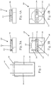
- a mold 150 is prepared by preparing a suitable mold material which is then disposed within a first mold container (vessel) 152.
- the first mold container 152 has a hollow interior and can have a rectangular shape.
- a predetermined amount of the mold material is then added to the hollow interior of the first mold container 152.
- the mold material is an Agarose hydrogel solution, such as a 2% Agarose solution, that provides structural support yet is permeable and non-adherent.
- about 20 mls of the Agarose solution is added to the first mold container 152.
- the mold is then prepared by introducing a mandrel 153 into the mold material.
- the mandrel 153 can be in the form of a cylindrical structure with a hemispherical tip, such as a test tube (e.g., a 13 mm test tube).
- the mandrel 153 is centered within the first mold container 152 and is also positioned such that it is normal (perpendicular) to the mold material within the first mold container 152. It will be appreciated that one mandrel 153 forms one mold cavity when the molding process is complete and the mandrel is withdrawn.
- the mandrel 153 can be suspended in the mold material using a first support member (cover) or first jig 200.
- the first jig 200 is designed to cover the first mold container 152 much like a shoe box cover covers the bottom of the box.
- the first jig 200 has a top surface 202 and side walls 204.
- the top surface 202 has an opening 206 formed therein, with the opening 206 being configured to receive the mandrel 153.
- the mandrel 153 can thus be supported by the first jig 200 such that the mandrel 153 can be locked in a desired position such that the desired spacing between the bottom of the mandrel 153 and the bottom of the first mold container 153 is achieved.
- the mandrel 153 can thus be slidingly moved within the opening 206 and a lock mechanism 210 can be used to lock the mandrel 153 in the desired position.
- a first set screw 212 that extends through one side wall 204 can be used to secure the mandrel 153 in place within the mold material that is within the first mold container 152.
- the set screw 212 is loosened to allow axial movement of the mandrel 153 and when the mandrel 153 is in the desired position, the set screw 212 is tightened.
- Other locking mechanisms can be used.
- the mandrel is positioned within the mold material (Agarose solution) so that there is about 0.5 to 0.75 cm of the mold material between the bottom of the mandrel and the bottom of the first mold container 152.
- the mandrel is carefully removed from the mold material leaving a void (e.g., the imprint of the test tube) in the mold material.
- This void defines the formed mold cavity 155 which is cup-shaped ( Figs. 1A and 6 ).
- the mold formed within the first mold container 152 is then placed under a UV light or the like to sterilize the mold.
- Additional steps can be performed to ready the mold for use. For example, about 1.5 ml of a sterile 2% BSA (bovine serum albumin) solution can be added to the mold and then the first mold container 152 is covered and the mold is incubated for a predetermined period of time (e.g., 1 hour at about 37°C). After the incubation period is completed, the mold can be washed with one or more solutions including a phosphate-buffered saline and deionized water. In one embodiment, the wash process involves washing the mold three times with a phosphate buffered saline solution and one time with deionized water. The deionized water is then removed from the mold and the mold is allowed to dry.
- BSA bovine serum albumin
- the mold 150 can thus be formed of 2% agarose in phosphate-buffered saline (PBS).
- PBS phosphate-buffered saline
- a second support member (cover) or first jig 220 is provided to mate with an open end of a vessel or container, such as first mold container 152.
- the second jig 220 is designed to cover the first mold container 152 and another vessel used subsequently as described below.
- the second jig 220 has a top surface 222 and side walls 224 (which can be fitted over the side walls of the vessel 300).
- the top surface 222 has a plurality of openings formed therein.
- the second jig 220 has three openings 230, 232, 234 formed therein, with the second opening 232 being the middle one.
- the openings 230, 232, 234 do not have to have the same characteristics (shapes and/or dimensions) and in the illustrated embodiment, the opening 232 is different than the openings 230, 234. More specifically, the opening 232 which represent a middle opening between the openings 230, 234 is larger (greater diameter) than the openings 230, 234.
- the second jig 220 has a lock mechanism for securely positioning and retaining members (tools/instruments) that are inserted into any one of the openings 230, 232, 234.
- a plurality of set screws 240 can be used and in particular, the set screws 240 pass through one or more of the side walls 224.
- the set screw 240 for the middle opening 232 passes through one side wall 224, while the other two set screws 240 for the openings 230, 234 pass through an opposite side wall 224 to facilitate unencumbered manipulation of individual set screws 240.
- the set screws 240 can be in the form of nylon screws to avoid corrosion and minimize damage to inserted tools/instruments.
- the middle opening 232 is constructed to receive the cannula 140.
- the distal end of the cannula 140 is thus passed through the middle opening 232 so as to position the distal end of the cannula 140 below the second jig 220.
- the cannula 140 includes the first ring 130 and the O-ring 135 (both of which are disposed at or near the distal end of the cannula).
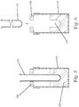
- the catheter 110 is passed through the lumen formed in the cannula 140.
- the balloon 120 is in a deflated state as the catheter 110 is passed through the lumen ( Fig. 7 ).
- the catheter 110 is advanced through the lumen until the balloon 120 extends beyond the open distal end of the cannula 140.
- the balloon 120 is then inflated as by injecting an inflation fluid (e.g., deionized water) into the balloon 120.
- an inflation fluid e.g., deionized water
- the catheter 110 is gently pulled back so as to position the inflated balloon 120 against the distal end of the cannula 140 ( Fig. 8 ).
- the inflated balloon 120 thus lies directly below the first ring 130 (support ring).
- the set screw 240 can be used to secure the cannula 140 in place relative to the second jig 220.
- the catheter 110 is typically a flexible member that is sized to be slightly smaller than the lumen of the cannula and therefore, a frictional coupling can be formed between the catheter 110 and the cannula 140. In any event, the catheter 110 slidingly travels within the lumen of the cannula 140 to permit repositioning thereof as well as insertion and removal of the catheter 110.
- the catheter 110 can be secured in the desired position using a retaining mechanism.
- a clamp 250 or the like can be used to hold the catheter 110 in place or a set screw can be used to apply tension on the catheter 110 that is within the lumen of the cannula 140.
- a frictional fit can exist between the catheter 110 and the cannula 140 and thus, the catheter 110 is frictionally held in place within the cannula 140.
- the second jig 220 is then inserted into the first mold container 152 that contains the formed cup-shaped agarose mold 150.
- the inflated balloon 120 can then be further manipulated where needed to position the balloon 120 in a target location in the cup-shaped mold cavity.
- the balloon 120 can be centered within the mold cavity such that there is approximately 2 mm of space, uniformly distributed, between the agarose wall and the balloon 120.
- the volume of the balloon 120 can also be adjusted to increase or decrease this gap spacing, which ultimately determines the wall thickness of the resulting organoid chamber.
- the position of the second jig 220 can be adjusted and in particular, the second jig 220 can be positioned at angle to aid in alignment of the balloon 120 within the mold cavity.
- the balloon 120 is also lowered within the mold cavity 155 until it is at a target location.
- the balloon 120 can be lowered until the balloon 120 is disposed approximately 2 mm from the bottom of the agarose mold.
- the balloon 120 can thus be concentrically located within the mold 150.
- the 2 mm sized spacing mentioned above is merely exemplary and not limiting of the present invention since in different applications, the dimension of this spacing can be different than 2 mm.
- the balloon 120 can be spaced (uniformly) from the mold a distance between about 0.5 mm and about 3mm. The gap is shown in an exaggerated state in the figures to allow the balloon and side walls of the mold cavity to be seen.
- human cardiomyocytes are used as part of the process for forming the human engineered cardiac organoid chamber (hCOC).
- hCMs human cardiomyocytes
- an ice-cold sterile collagen solution is prepared using purified bovine dermal type 1 collagen. This gel is mixed with Matrigel basement membrane matrix and a cell suspension according to a predetermined ratio. This results in a cold cell-matrix solution being formed and the detailed Example set forth below describes the detailed steps for creating one cold cell-matrix solution.
- One of the unoccupied openings 230, 234 can be used as a media access port or a dedicated port 235 can be formed for delivering the cold cell-matrix solution (tissue culture mixture) into the mold cavity 155 using a suitable instrument ( Fig. 1A ).
- a pipette e.g., a 1000 mL pipet
- the cold cell-matrix solution thus flows around the inflated balloon 120 and is contained within the mold cavity 155 defined by the gap space between the outer cup-shaped mold 150 and around the inflated balloon 120 and the cannula 140.
- the first ring 130 is to be entirely submerged in the cold cell-matrix solution and thus, the axial position of the balloon 120, or the volume of the cold cell-matrix solution, can be adjusted to ensure that the first ring 130 remains submerged.
- the first ring 130 serves to prevent tissue slippage during tissue culture.
- the entire assembly is then incubated under prescribed conditions that result in initiation of collagen gel polymerization.
- the assembly can be incubated at 37°C in 20% O 2 , 5% CO 2 and 95% ambient humidity for two hours.
- the tissues can be "floated" two hours later by adding enough neonatal bovine serum (NBS)-supplemented culture media to completely submerge the tissue and then the assembly can be returned to the incubator ( Fig. 1A ).
- NBS neonatal bovine serum
- the jig assembly (defined by the jig 220 and attached cannula 140 and balloon catheter 110) is removed from the mold cavity 155.
- the jig assembly is then placed on top of a second container 300 which can be similar or identical to the first mold container 152 with the exception that the second container 300 does not include an agarose mold and instead is empty.
- the dimensions of the second container 300 can be the same as the first container 152.
- the second container 300 is also sterilized prior to mating the jig assembly to the open top of the second container 300.
- a culture media is then added to the second container 300 through the media access port (e.g., opening 235) formed in the second jig 220 ( Fig. 1B ). Half of the culture media is renewed daily.
- the media access port e.g., opening 235
- the balloon 120 remains inflated and the first ring 130 remains immediately above the inflated balloon 120 and surrounds the cannula 140.
- the second container 300 with the culture media is maintained in the incubator for a predetermined period of time, such as 7 to 10 days.
- the myocytes begin contracting and forming a coordinated network as the engineered tissue becomes compacted around the balloon 120.
- an engineered cardiac organoid chamber is generated around the balloon 120 and once the balloon 120 is removed, an organoid 199 ( Fig. 1C ) remains in place and is sealingly coupled to the first ring 130 disposed about the cannula 140.
- beating cardiac chambers were created from human cardiac cells.
- the present invention combines organoid chamber engineering techniques with human cardiomyocytes derived from pluripotent stem cells. This combination results in a unique human beating heart chamber that provides a new bridge between traditional in vitro culture systems and preclinical testing in animals and human patients.
- Tissue e.g ., Organoid Pump Function
- the spontaneously beating cardiac organoid is prepared for testing.
- pacing and mapping experiments can be performed beginning at around day 7 to 10.
- the catheter 110 is removed from the jig assembly by first deflating the balloon 120 carefully while leaving behind the cardiac organoid.
- the clamp 250 ( FIG. 1C ) is loosened to allow for removal of the catheter 110.
- One technique for removing the catheter 110 is to gently twist the catheter 110 back and forth to check for any attachment of the tissue to the balloon 120. If any attachment of the tissue is noticed, the tissue can be returned to the incubator for 15 minutes as this usually helps the tissue detach from the balloon 120.
- the catheter 110 is then gently withdrawn (removed) out of the open proximal end of the cannula 140 (see Fig. 1C ).
- a small amount (100-200 ⁇ l) of NBS media can be added to the open proximal end of the cannula 140 as the catheter 110 is removed.
- a vacuum forms in the mold cavity (chamber) as the catheter 110 is removed. Adding the NBS media can help mitigate the vacuum if formed.
- the catheter 110 can be twisted back and forth as this also aids in releasing any vacuum.
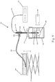
- the tissue is tested in a closed-loop system 400 such as the one shown in Fig. 9 (which is a schematic of one exemplary organoid function testing system).
- the system 400 includes the bioreactor 100 and in particular, the second container 300 that is filled with culture media with the organoid shown at 199.
- the organoid 199 generated according to the teachings of the present invention is grown in-situ about the cannula 140 and in particular, the organoid 199 is attached to the cannula 140 via the porous support ring 130 and the water-tight O-ring seal 135 to prevent fluid leakage.
- a connector 410 such as a T-connector, is sealingly and fluidly connected to the open proximal end of the cannula 140.
- the connector 410 thus has a first leg 412 and a second leg 414 to which other objects can be attached.
- An open fluid reservoir 420 is sealingly connected to the first leg 412 by a conduit 430.
- the open fluid reservoir 420 contains the culture media and can include additional substances, such as phenol red to enable pH to be monitored and enhance the organoid image contrast.
- the conduit 430 can be in the form of flexible tubing which allows flow of the culture media.
- the mean chamber pressure (within the organoid 199) can be controlled by adjusting the height of the open fluid reservoir 420 and in particular, the open fluid reservoir 420 can sit on an adjustable platform (jack 425) that allows the height of the reservoir 420 to be adjusted (e.g., manually or via motor control) to control the hydrostatic pressure load on the organoid 199.
- Chamber pressures are measured relative to the external reservoir 420 using a suitable pressure transducer 440, such as an indwelling electronic pressure transducer.
- the transducer 440 has a probe element 442 that passes through the second leg 414 and through the lumen of the cannula 140 into the center of the organoid 199.
- the probe element 442 is sealed to second leg 414 with a suitable sealing material 415, such as a wad of malleable gum to maintain a closed fluid connection via the conduit 430 which is connected to the open fluid reservoir 420.
- a suitable sealing material 415 such as a wad of malleable gum to maintain a closed fluid connection via the conduit 430 which is connected to the open fluid reservoir 420.
- the resulting passive and active pressures within the organoid chamber are recorded by the pressure transducer 440 to assess contractile function.
- a high-speed video camera (digital camera) 450 is used to monitor changes in organoid size synchronized with the pressure recordings.
- a pair of electrodes 500 (connected to an electrical stimulator apparatus) is used to electrically pace the organoid chamber using a technique known as electrical field stimulation.
- the electrodes 500 are received through openings 230, 234 formed in the top of the second jig 220. Since the openings 230, 234 are at a fixed, spaced relationship relative to the opening 232, the electrodes 500 are maintained at a fixed position and spaced a fixed distance from the cannula 140 (and thus from the organoid), to ensure a well-defined electrical field gradient during pacing.
- any number of techniques can be used to securely attach or couple the electrodes 500 to the second jig 220, such as nylon set screws 240.
- the electrodes 500 depend downwardly into the culture media and are at least generally parallel to the cannula 140.
- the electrodes 500 can be selected from any number of suitable conductive and non-corrosive electrode materials, including carbon rod electrodes. The electrodes 500 are thus proximate and spaced from the organoid 199 that is attached to the first ring 130 at the distal end of the cannula 140.
- a resulting extracellular electrogram can be recorded using conventional devices, such as a microelectrode AC amplifier that includes a band-pass filter and is sampled at a predetermined frequency.
- Extracellular voltage, chamber pressure, and digital video can be acquired simultaneously using an A/D converter on a personal computer.
- Chamber cross-sectional area can be measured from the digital video by applying grayscale threshold and automatic detection of the tissue boundary using suitable image processing software, such as ImageJ.
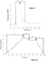
- the following graphs show pressure within the organoid chamber versus time without the O-ring seal 135 ( Fig. 11 ) and with the O-ring seal 135 ( Fig. 12 ).
- the pressure data are measured using a Millar Mikro-Tip pressure transducer threaded through the cannula 140 and into the organoid lumen, with the end of the tube/transducer sealed with modeling clay to create a closed fluid system ( Fig. 10 ).
- the data in Fig. 11 clearly shows that without the O-ring seal 135, the pressure load on the organoid can be increased but it rapidly falls as the fluid leaks out of the system.
- Fig. 11 Organoid chamber pressure versus time during example test without the rubber O-ring seal in place.
- the pressure is increased by about 8 mmH2O (Region A)
- the pressure is not held steady, and rapidly falls back toward baseline in less than 10 seconds (Region B) due to fluid leaking out of the chamber.
- oscillations in the pressure signal are due to beating of the organoid during testing. Accurate analysis of these oscillations is greatly hampered by the non-steady nature of the loading pressure.
- Fig. 12 Organoid chamber pressure versus time during example test with the rubber O-ring seal in place. Region A shows incremental step loading of approximately 5 mmH2O every 5 seconds from baseline of about 2 mmH2O up to 40 mmH2O. The steady regions after each increment demonstrate that the closed system is able to hold constant pressures. After some adjustment near the maximum (Region B), the pressure was reduced to approximately 35 mmH2O and held steady for about 20 seconds (Region C), indicating no appreciable fluid leakage in the system. The pressure was then rapidly reduced back to zero at the end of the test (Region C), indicating an ability to accurately control the organoid chamber pressure over a wide range. Note the difference in scale for both the pressure axis and the time axis in Fig. 11 , which is very zoomed in compared to Fig. 12 .
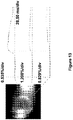
- Fig. 13 Organoid chamber during optical mapping of electrical signals.
- the image shows pseudo-color of fluorescence intensity using voltage-sensitive fluorescent dye (di-4-ANEPPS), with individual tracings of signal intensity (i.e. voltage) vs. time at multiple sites on the organoid, indicating propagation of the electrical wave from left to right.
- di-4-ANEPPS voltage-sensitive fluorescent dye
- the construction of the bioreactor 100 and related equipment overcomes the deficiencies associated with the conventional equipment in that the organoid chamber is grown directly on an instrument, in this case the cannula 140, that is configured to be used in the testing phase as well as the initial culturing phase in which the organoid is generated.
- the construction of the bioreactor 100 of the present invention thus avoids the need to physically detach the organoid from the balloon catheter and then transfer and attach the organoid to a test instrument, such as pressure transducer equipment, using a suture or similar method-this process often results in damage to the organoid and compromises sterility and viability of the living engineered tissue.
- the human organoid chambers and the related bioreactor systems disclosed herein have a vast number of practical applications for creating functional in vitro models the human heart with biomimetic structural and functional properties for enhanced drug/toxicity screening and other (cell, gene) therapeutic discovery/preclinical testing applications. Accordingly, by creating a biomimetic in vitro surrogate for the human heart, the present technology helps bridge the longstanding gap between traditional cell culture systems and in vivo animal models and eventual clinical trials.
- the present invention essentially provides an in vitro preclinical human organ model with reduced and controlled biocomplexity for improved screening applications that can improve the efficiency and success rate of novel or repurposed drugs.
- Creating tissues from human adult pluripotent stem cells e.g., iPSCs
- the human organoid chambers generated using the bioreactor systems disclosed herein are also uniquely suitable when clinically relevant pressure-volume characteristics are required, or when optical mapping of electrophysiological characteristics is of interest.
- 3D cell alignment is generated by silicone balloon surface patterning. More specifically, various surface patterns can be formed on the outer surface of the balloon 120. These textured balloons induce cell and matrix alignment in the 3D organoid chambers, more like the natural heart wall.
- the resulting anisotropy fundamentally impacts the structural organization of the tissue as well as the resulting mechanical properties and electrical conduction properties, providing a novel strategy to improve overall pump function of the organoids.
- the hCMs are ready for use after the single cells have re-aggregated into small clusters of cells (such as a cluster of 15-20 cells).
- the plate on which the hCMs are present should be inspected prior to cell transfer and is a substantial number of cells have attached to the plate, the cells can be scraped with a cell lifter, such as a Corning cell lifter.
- the cell/tissue culture is then further prepared by performing the steps of: pelleting the cells (300 x g for a selected time period (e.g., three minutes)) and then aspirating off the supernatant, leaving approximately 500 ⁇ L of solution (resulting solution).
- the supernatant is then resuspended in the 500 ⁇ L of solution and is transferred to a different vessel, such as an Eppendorf tube.
- the cells undergo a pelleting procedure again (200 x g) in a microfuge for a predetermined period of time (e.g., 5 minutes).
- the resulting solution (tissue culture) is then set aside.
- the cannula 140 can have one or more of the following features/properties:
- the porous support ring (first ring 130) can be in the form of a ring that is formed (cut/stamped) from a 1/16" thick sheet of hydrophilic-treated porous polyethylene with 70-um pore size; however, the first ring 130 can be formed from other suitable materials and have other properties.
- the porous support ring 130 can have one or more of the following features/properties:
- the first ring 130 can be cut from 1/16" thick sheet of hydrophilic-treated porous polyethylene with 70-um pore size.
- the O-ring 135 can be a silicone rubber O-ring with an inner diameter of about 5/64" and an outer diameter of about 13/64", with a thickness of about 1/16".
- the O-ring 135 can have one or more of the following features:
- the O-ring 135 and porous ring 130 can be coupled to one another (at least temporarily) prior to coupling to the cannula 140.
- Bovine Type I Collagen (Life Technologies, Cat # A10644-01) 10x Minimum Essential Medium Eagle (MEM) (Sigma, Cat # M0275) Bovine Serum Albumin (Sigma, Cat # A9418) High Vacuum Grease (Dow Corning) (Fisher Scientific, Cat # 146355D) PBS (Sigma, Cat # P3813) Matrigel - hESC-qualified matrix (BD Biosciences, Cat # 354277) in 150 ⁇ L aliquots HEPES (Sigma, Cat # H4034) Dulbecco's Modified Eagle's Medium (DMEM) - high glucose (Sigma, Cat # D5648) Neonatal Bovine Serum (NBS) (Atlanta Biologics, Cat # S11250) Penicillin-Streptomycin (Pen-Strep) (CellGro, Cat # 30-002-CI) Amphotericin B (Sigma, Cat # A2411-1G) Agarose I (VWR, Cat # 0710-25G) Silicon
Landscapes
- Health & Medical Sciences (AREA)
- Life Sciences & Earth Sciences (AREA)
- Engineering & Computer Science (AREA)
- Wood Science & Technology (AREA)
- Organic Chemistry (AREA)
- Bioinformatics & Cheminformatics (AREA)
- Chemical & Material Sciences (AREA)
- Zoology (AREA)
- Genetics & Genomics (AREA)
- Biotechnology (AREA)
- Biomedical Technology (AREA)
- Biochemistry (AREA)
- Sustainable Development (AREA)
- General Engineering & Computer Science (AREA)
- General Health & Medical Sciences (AREA)
- Microbiology (AREA)
- Clinical Laboratory Science (AREA)
- Molecular Biology (AREA)
- Physics & Mathematics (AREA)
- Electromagnetism (AREA)
- Cell Biology (AREA)
- Apparatus Associated With Microorganisms And Enzymes (AREA)
Claims (15)
- Bioreaktorsystem zum Präparieren einer Herzorganoidkammer und zum anschließenden Testen derselben, umfassend:ein erstes Gefäß mit einem hohlen Innenraum und einem offenen Oberteil;eine erste Abdeckung zum Zusammenpassen mit der offenen Oberseite des ersten Gefäßes, wobei die erste Abdeckung eine darin ausgebildete erste Öffnung aufweist;eine Kanüle mit einem Lumen, das sich von einem offenen ersten Ende zu einem offenen zweiten Ende erstreckt, wobei die Kanüle in der ersten Öffnung der ersten Abdeckung derart angeordnet ist, dass ein Abschnitt der Kanüle unter der ersten Abdeckung und zum Einsetzten in den hohlen Innenraum des ersten Gefäßes liegt;einen porösen Ring, der mit der Kanüle an oder in der Nähe des offenen zweiten Endes davon gekoppelt ist; undeinen Ballonkatheter mit einem aufblasbaren Ballon an einem distalen Ende eines Katheterschafts, wobei der Ballonkatheter angepasst ist, durch das Lumen der Kanüle zu treten, wenn sich der Ballon in einem deflatierten bzw. entlüfteten Zustand befindet, wobei der Ballonkatheter axial innerhalb des Lumens einstellbar ist, um dem Ballon in einem aufgeblasenen Zustand zu erlauben, benachbart zu bzw. angrenzend an angeordnet zu werden: (1) dem offenen zweiten Ende der Kanüle; und (2) dem porösen Ring zum Präparieren der Herzorganoidkammer um den aufgeblasenen Ballon und den porösen Ring herum.
- System nach Anspruch 1, wobei die erste Öffnung in einer oberen Wand der ersten Abdeckung ausgebildet ist und die erste Abdeckung eine zweite und eine dritte Öffnung enthält, die in der oberen Wand ausgebildet sind, wobei die erste Öffnung zwischen der zweiten und dritten Öffnung ausgebildet ist.
- System nach Anspruch 2, wobei die erste Abdeckung ein Mittel zum sicheren Koppeln der Kanüle mit der ersten Abdeckung aufweist.
- System nach Anspruch 3, wobei das Mittel ein mechanisches Rückhalteglied umfasst, das die Kanüle in einer gewünschten Position innerhalb der ersten Öffnung und relativ zu der ersten Abdeckung hält und zurückhält.
- System nach Anspruch 4, wobei das mechanische Rückhalteglied eine Stellschraube umfasst, die sich durch eine Seitenwand der ersten Abdeckung erstreckt, um eine Rückhaltekraft gegen die Kanüle aufzubringen.
- System nach einem der Ansprüche 1-5, wobei die Kanüle aus einem Material gebildet ist, das aus einem Metall und einem starren Kunststoff ausgewählt ist, und der poröse Ring aus einem hydrophilen porösen Polyethylenmaterial gebildet ist.
- System nach Anspruch 1, wobei der poröse Ring konfiguriert ist, ein Gewebeabrutschen während der Gewebezücktung zu verhindern, um die Herzorganoidkammer zu bilden.
- System nach Anspruch 1, ferner umfassend einen O-Ring, der um die Kanüle herum angeordnet ist und in engem Kontakt mit einer oberen Fläche bzw. Oberfläche des porösen Rings steht, wobei der O-Ring konfiguriert ist, eine wasserdichte Abdichtung bereitzustellen.
- System nach einem der Ansprüche 1-5, wobei der Ballonkatheter einen flexiblen Schaft aufweist, der reibschlüssig in das Lumen der Kanüle gepasst ist, um eine relative Position des Ballonkatheters relativ zu der Kanüle zu fixieren.
- System nach Anspruch 9, wobei eine externe Vorrichtung verwendet wird, um den Ballonkatheter innerhalb des Lumens des Katheters zurückzuhalten, so dass der Ballonkatheter an einer festen Stelle innerhalb des Lumens verbleibt, wobei der aufgeblasene Ballon benachbart zu dem offenen zweiten Ende der Kanüle und dem porösen Ring gehalten ist.
- System nach einem der Ansprüche 2-5, ferner umfassend ein Paar Elektroden, die in der zweiten und dritten Öffnung angeordnet sind, um elektrophysiologisch gesteuerte Messungen oder eine chronische elektrische Stimulation während der Züchtung in bzw. an der vorbereiteten Herzorganoidkammer zu ermöglichen, und wobei die erste Abdeckung ein Mittel zum sicheren Koppeln des Elektrodenpaars mit der ersten Abdeckung aufweist.
- System nach einem der Ansprüche 1-5, wobei der aufblasbare Ballon ein Flächen- bzw. Oberflächenmuster enthält, das auf einer äußeren Fläche bzw. Oberfläche davon ausgebildet ist, um eine Zell- und Matrixausrichtung in der 3D-präparierten Herzorganoidkammer zu induzieren.
- System nach einem der Ansprüche 1-5, ferner umfassend:
ein Organoidfunktiontestsystem mit geschlossenem Regelkreis, das umfasst:einen Verbinder, der an dem offenen ersten Ende der Kanüle angebracht ist, wobei der Verbinder mittels einer Leitung mit einem offenen Fluidreservoir fluidisch verbunden ist;einen Druckwandler mit einer Sonde, die durch das Lumen der Kanüle geführt werden kann, nachdem die Herzorganoidkammer konstruiert wurde und der Ballonkatheter von der Kanüle entfernt wurde, wobei der Druckwandler konfiguriert ist, einen Kammerdruck innerhalb der konstruierten Herzorganoidkammer zu messen; undeine Abbildungsvorrichtung zum Überwachen von Änderungen der Größe des Organoids. - System nach Anspruch 13, wobei die Abbildungsvorrichtung eine Hochgeschwindigkeitsvideokamera umfasst, die mit dem Druckwandler synchronisiert ist, um zu ermöglichen, dass Änderungen der Organoidgröße mit Kammerdruckmessungen synchronisiert werden, die von dem Druckwandler aufgezeichnet werden.
- Verfahren zum Konstruieren einer Herzorganoidkammer, umfassend die Schritte:Präparieren einer Form in einem ersten Gefäß, wobei die Form einen offenen Formhohlraum enthält;Positionieren einer Kanüle innerhalb des offenen Formhohlraums, wobei die Kanüle einen porösen Ring aufweist, der um ein distales Ende der Kanüle herum angeordnet ist, die innerhalb des offenen Formhohlraums angeordnet ist;Einsetzen und Führen eines Ballonkatheters durch ein in der Kanüle ausgebildetes Lumen, so dass ein aufblasbarer Ballon jenseits des distalen Endes der Kanüle liegt;Aufblasen des Ballons und Positionieren des Ballonkatheters derart, dass der aufgeblasene Ballon benachbart zu bzw. angrenzend an das distale Ende der Kanüle und dem porösen Ring angeordnet ist;Aussetzen des ersten Gefäßes Inkubationsbedingungen für einen ersten Zeitraum, um die Gewebebildung an dem aufgeblasenen Ballon und dem porösen Ring zu fördern;Entfernen der kombinierten Kanüle und des Ballonkatheters aus dem ersten Gefäß und Einsetzen der kombinierten Kanüle und des Ballonkatheters in ein zweites Gefäß, das Zellkulturmedium enthält; undAussetzen des zweiten Gefäßes Inkubationsbedingungen für einen zweiten Zeitraum, was in einer konstruierten Herzorganoidkammer resultiert, die um den aufgeblasenen Ballon und den porösen Ring herum gebildet wird.
Applications Claiming Priority (2)
| Application Number | Priority Date | Filing Date | Title |
|---|---|---|---|
| US201462004467P | 2014-05-29 | 2014-05-29 | |
| PCT/US2015/033206 WO2015184273A1 (en) | 2014-05-29 | 2015-05-29 | Method and apparatus to prepare cardiac organoids in a bioreactor system |
Publications (3)
| Publication Number | Publication Date |
|---|---|
| EP3149147A1 EP3149147A1 (de) | 2017-04-05 |
| EP3149147A4 EP3149147A4 (de) | 2018-05-02 |
| EP3149147B1 true EP3149147B1 (de) | 2019-08-21 |
Family
ID=54699868
Family Applications (1)
| Application Number | Title | Priority Date | Filing Date |
|---|---|---|---|
| EP15800086.9A Active EP3149147B1 (de) | 2014-05-29 | 2015-05-29 | Verfahren und vorrichtung zur herstellung von herzorganoiden in einem bioreaktorsystem |
Country Status (4)
| Country | Link |
|---|---|
| US (1) | US10683476B2 (de) |
| EP (1) | EP3149147B1 (de) |
| CN (1) | CN106536707B (de) |
| WO (1) | WO2015184273A1 (de) |
Families Citing this family (25)
| Publication number | Priority date | Publication date | Assignee | Title |
|---|---|---|---|---|
| US9719068B2 (en) | 2010-05-06 | 2017-08-01 | Children's Hospital Medical Center | Methods and systems for converting precursor cells into intestinal tissues through directed differentiation |
| SG10201801654RA (en) | 2014-05-28 | 2018-04-27 | Childrens Hospital Med Ct | Methods and systems for converting precursor cells into gastric tissues through directed differentiation |
| AU2015331848B2 (en) | 2014-10-17 | 2022-03-03 | Children's Hospital Medical Center, D/B/A Cincinnati Children's Hospital Medical Center | In vivo model of human small intestine using pluripotent stem cells and methods of making and using same |
| CN109415685B (zh) | 2016-05-05 | 2023-07-04 | 儿童医院医疗中心 | 用于体外制造胃底组织的方法和与其相关的组合物 |
| EP4553082A3 (de) | 2016-11-04 | 2025-08-20 | Children's Hospital Medical Center | Leberorganoidzusammensetzungen und verfahren zur herstellung und verwendung davon |
| EP3548507A4 (de) | 2016-12-05 | 2020-07-15 | Children's Hospital Medical Center | Kolonorganoide und verfahren zur herstellung und verwendung davon |
| JP7248586B2 (ja) | 2017-04-14 | 2023-03-29 | チルドレンズ ホスピタル メディカル センター | 複数ドナー幹細胞組成物およびそれを作製する方法 |
| EP3681998A1 (de) | 2017-09-11 | 2020-07-22 | IMBA-Institut für Molekulare Biotechnologie GmbH | Tumororganoidmodell |
| EP3694603B1 (de) | 2017-10-10 | 2026-04-08 | Children's Hospital Medical Center | Ösophagusgewebe- und/oder organoidzusammensetzungen und verfahren zu ihrer herstellung |
| EP3727394A4 (de) | 2017-12-21 | 2021-09-08 | Children's Hospital Medical Center | Digitalisierte menschliche organoide und verfahren zu deren verwendung |
| CN112055600A (zh) * | 2018-03-07 | 2020-12-08 | 特温特大学 | 用于制备中空3d细胞组织结构的模具和方法 |
| EP3775886A4 (de) * | 2018-03-28 | 2022-01-12 | Novoheart Limited | Modellierung von neurologischen störungen und ataxien mit herzdysfunktion unter verwendung von biotechnologisch hergestellten herzgeweben |
| EP4678727A3 (de) | 2018-07-26 | 2026-03-11 | Children's Hospital Medical Center | Hepatobiliäres bauchspeicheldrüsengewebe und verfahren zur herstellung davon |
| ES2746033A1 (es) | 2018-09-04 | 2020-03-04 | Univ Santiago Compostela | Sistema para el cultivo de organoides |
| CA3112026A1 (en) | 2018-09-12 | 2020-03-19 | Children's Hospital Medical Center | Organoid compositions for the production of hematopoietic stem cells and derivatives thereof |
| CA3124904A1 (en) | 2019-01-14 | 2020-07-23 | President And Fellows Of Harvard College | Focused rotary jet spinning devices and methods of use thereof |
| US12600943B2 (en) | 2019-02-01 | 2026-04-14 | The University Of Hong Kong | Innervated organoid compositions and methods of making same |
| US11259687B2 (en) | 2019-04-04 | 2022-03-01 | Biosense Webster (Israel) Ltd. | Medical instrument calibration |
| US12024696B2 (en) * | 2019-05-08 | 2024-07-02 | Molecular Devices (Austria) GmbH | System and method for organoid culture |
| AU2020283048A1 (en) | 2019-05-31 | 2021-12-23 | Children's Hospital Medical Center | Shaped organoid compositions and methods of making same |
| US12497597B2 (en) | 2019-05-31 | 2025-12-16 | Children's Hospital Medical Center | Methods of generating and expanding hematopoietic stem cells |
| EP3933028A1 (de) * | 2020-06-30 | 2022-01-05 | Novoheart Limited | Vorrichtungen mit organoiden kammern und deren verwendungen zur züchtung, erhaltung, überwachung oder untersuchung von organoiden |
| EP4179065A4 (de) * | 2020-07-09 | 2024-09-11 | Novoheart International Limited | Träger und system für manipuliertes gewebe |
| CN112501019B (zh) * | 2020-12-03 | 2023-10-31 | 广州迈普再生医学科技股份有限公司 | 一种多功能生物反应器 |
| CN113943649A (zh) * | 2021-08-31 | 2022-01-18 | 宁夏宁杨食品有限公司 | 一种豆瓣酱恒温发酵罐 |
Citations (1)
| Publication number | Priority date | Publication date | Assignee | Title |
|---|---|---|---|---|
| WO2010037783A1 (en) | 2008-10-03 | 2010-04-08 | Dsm Ip Assets B.V. | Process to make food or feed flavour with glutathione or cystein |
Family Cites Families (5)
| Publication number | Priority date | Publication date | Assignee | Title |
|---|---|---|---|---|
| AU2001243581A1 (en) * | 2000-03-11 | 2001-09-24 | The Trustees Of Columbia University In The City Of New York | Bioreactor for generating functional cartilaginous tissue |
| US20020106625A1 (en) * | 2002-02-07 | 2002-08-08 | Hung Clark T. | Bioreactor for generating functional cartilaginous tissue |
| EP2282801A1 (de) * | 2008-05-01 | 2011-02-16 | Edwards Lifesciences Corporation | Vorrichtung und verfahren zur ballonexpansion |
| US20100249491A1 (en) | 2009-03-27 | 2010-09-30 | Circulite, Inc. | Two-piece transseptal cannula, delivery system, and method of delivery |
| FR2971255B1 (fr) | 2011-02-04 | 2015-03-27 | Centre Nat Rech Scient | Bioreacteur pour la culture cellulaire sur substrat tridimensionnel |
-
2015
- 2015-05-29 CN CN201580039283.3A patent/CN106536707B/zh not_active Expired - Fee Related
- 2015-05-29 WO PCT/US2015/033206 patent/WO2015184273A1/en not_active Ceased
- 2015-05-29 EP EP15800086.9A patent/EP3149147B1/de active Active
- 2015-05-29 US US15/314,870 patent/US10683476B2/en active Active
Patent Citations (1)
| Publication number | Priority date | Publication date | Assignee | Title |
|---|---|---|---|---|
| WO2010037783A1 (en) | 2008-10-03 | 2010-04-08 | Dsm Ip Assets B.V. | Process to make food or feed flavour with glutathione or cystein |
Non-Patent Citations (4)
| Title |
|---|
| "Practical Methods in Cardiovascular Research", 1 January 2005, SPRINGER-VERLAG, Berlin/Heidelberg, ISBN: 978-3-540-40763-8, article WOLFRAM-HUBERTUS ZIMMERMANN, IVAN MELNYCHENKO, MICHAEL DIDIÉ, ALI EL-ARMOUCHE, THOMAS ESCHENHAGEN: "Engineering Heart Tissue for In Vitro and In Vivo Studies", pages: 640 - 658, XP055754068, DOI: 10.1007/3-540-26574-0_34 |
| ESCHENHAGEN T, ET AL.: "THREE-DIMENSIONAL RECONSTITUTION OF EMBRYONIC CARDIOMYOCYTES IN A COLLAGEN MATRIX: A NEW HEART MUSCLE MODEL SYSTEM", THE FASEB JOURNAL, FEDERATION OF AMERICAN SOCIETIES FOR EXPERIMENTAL BIOLOGY, US, vol. 11, no. 08, 1 January 1997 (1997-01-01), US, pages 683 - 694, XP001109636, ISSN: 0892-6638 |
| EUN JUNG LEE ET AL: "Engineered Cardiac Organoid Chambers: Toward a Functional Biological Model Ventricle", TISSUE ENGINEERING PART A, MARY ANN LIEBERT, US, vol. 14, no. 2, 1 February 2008 (2008-02-01), US, pages 215 - 225, XP055460747, ISSN: 1937-3341, DOI: 10.1089/tea.2007.0351 |
| SEBASTIAN SCHAAF, AYA SHIBAMIYA, MARCO MEWE, ALEXANDRA EDER, ANDREA ST�HR, MARC N. HIRT, THOMAS RAU, WOLFRAM-HUBERTUS ZIMMERMANN, : "Human Engineered Heart Tissue as a Versatile Tool in Basic Research and Preclinical Toxicology", PLOS ONE, vol. 6, no. 10, pages e26397, XP055083859, DOI: 10.1371/journal.pone.0026397 |
Also Published As
| Publication number | Publication date |
|---|---|
| WO2015184273A1 (en) | 2015-12-03 |
| US20170107469A1 (en) | 2017-04-20 |
| EP3149147A1 (de) | 2017-04-05 |
| US10683476B2 (en) | 2020-06-16 |
| CN106536707B (zh) | 2018-12-25 |
| CN106536707A (zh) | 2017-03-22 |
| EP3149147A4 (de) | 2018-05-02 |
Similar Documents
| Publication | Publication Date | Title |
|---|---|---|
| EP3149147B1 (de) | Verfahren und vorrichtung zur herstellung von herzorganoiden in einem bioreaktorsystem | |
| Li et al. | Stretchable mesh microelectronics for the biointegration and stimulation of human neural organoids | |
| CA2612269C (en) | Method of producing organotypic cell cultures | |
| JP2008529691A (ja) | 組織工学によるプロテーゼの製造方法 | |
| JP2004500093A (ja) | 3次元マトリックス体、細胞組織の収縮を測定する装置および方法 | |
| CN112771151B (zh) | 利用细胞培养用载体制备的类器官及利用其的药物毒性评价方法 | |
| KR20050105479A (ko) | 생물 세포 물질을 통한 프로브의 손상이 없는 이동을 위한방법 및 장치 | |
| EP2720731A1 (de) | Systeme, verfahren und vorrichtung in zusammenhang mit einer biomimetischen zell-nephroneinheit | |
| US20110014597A1 (en) | Perfusable Bioreactor for the Production and/or Cultivation of a Human or Animal Blood Vessel and/or a Human or Animal Tissue | |
| WO2019156941A1 (en) | Tissue engineered scaffolds, instrumented bioreactors and methods of use thereof | |
| EP3620508B1 (de) | Mikrofluidische vorrichtung zur elektrischen messung und/oder stimulation | |
| HK1236220B (en) | Method and apparatus to prepare cardiac organoids in a bioreactor system | |
| HK1236220A1 (en) | Method and apparatus to prepare cardiac organoids in a bioreactor system | |
| CN121263181A (zh) | 作为sumo激活和e1连接酶激活化合物用于治疗心血管疾病的甲酰胺化合物 | |
| US20230257711A1 (en) | Support and System for Engineered Tissue | |
| KR20240014423A (ko) | 역-미세둑 구조가 포함된 장기모사칩 및 이의 용도 | |
| CN222524564U (zh) | 一种多通量实时电监测心脏芯片 | |
| CN217525302U (zh) | 一种微型干细胞脊髓原位定向多次输注与活体取样装置 | |
| US20240228934A9 (en) | Nonclinical method for testing medical device surface interactions with migrating cells in simulated in vivo environment | |
| Linares | Microfluidic Platforms for Retina Electrophysiology Studies | |
| CN120519285A (zh) | 一种分离式类器官芯片模型及其使用方法 | |
| Gawlitta et al. | In Vitro Muscle Model Studies | |
| Vernekar | Optimization of 3-D neural culture and extracellular electrophysiology for studying injury-induced morphological and functional changes | |
| Naraghi et al. | Novel Imaging Technologies and Their Role in Medicine: A Review | |
| Dodson | Microfluidic Platforms for Chemical and Electrical Signaling in Whole Retina Tissue |
Legal Events
| Date | Code | Title | Description |
|---|---|---|---|
| STAA | Information on the status of an ep patent application or granted ep patent |
Free format text: STATUS: THE INTERNATIONAL PUBLICATION HAS BEEN MADE |
|
| PUAI | Public reference made under article 153(3) epc to a published international application that has entered the european phase |
Free format text: ORIGINAL CODE: 0009012 |
|
| STAA | Information on the status of an ep patent application or granted ep patent |
Free format text: STATUS: REQUEST FOR EXAMINATION WAS MADE |
|
| 17P | Request for examination filed |
Effective date: 20161227 |
|
| AK | Designated contracting states |
Kind code of ref document: A1 Designated state(s): AL AT BE BG CH CY CZ DE DK EE ES FI FR GB GR HR HU IE IS IT LI LT LU LV MC MK MT NL NO PL PT RO RS SE SI SK SM TR |
|
| AX | Request for extension of the european patent |
Extension state: BA ME |
|
| DAV | Request for validation of the european patent (deleted) | ||
| DAX | Request for extension of the european patent (deleted) | ||
| REG | Reference to a national code |
Ref country code: HK Ref legal event code: DE Ref document number: 1236220 Country of ref document: HK |
|
| REG | Reference to a national code |
Ref country code: DE Ref legal event code: R079 Ref document number: 602015036379 Country of ref document: DE Free format text: PREVIOUS MAIN CLASS: C12M0001000000 Ipc: C12M0003000000 |
|
| A4 | Supplementary search report drawn up and despatched |
Effective date: 20180406 |
|
| RIC1 | Information provided on ipc code assigned before grant |
Ipc: C12N 5/00 20060101ALI20180329BHEP Ipc: C12M 3/00 20060101AFI20180329BHEP |
|
| GRAP | Despatch of communication of intention to grant a patent |
Free format text: ORIGINAL CODE: EPIDOSNIGR1 |
|
| STAA | Information on the status of an ep patent application or granted ep patent |
Free format text: STATUS: GRANT OF PATENT IS INTENDED |
|
| INTG | Intention to grant announced |
Effective date: 20190314 |
|
| GRAS | Grant fee paid |
Free format text: ORIGINAL CODE: EPIDOSNIGR3 |
|
| GRAA | (expected) grant |
Free format text: ORIGINAL CODE: 0009210 |
|
| STAA | Information on the status of an ep patent application or granted ep patent |
Free format text: STATUS: THE PATENT HAS BEEN GRANTED |
|
| AK | Designated contracting states |
Kind code of ref document: B1 Designated state(s): AL AT BE BG CH CY CZ DE DK EE ES FI FR GB GR HR HU IE IS IT LI LT LU LV MC MK MT NL NO PL PT RO RS SE SI SK SM TR |
|
| REG | Reference to a national code |
Ref country code: GB Ref legal event code: FG4D |
|
| REG | Reference to a national code |
Ref country code: CH Ref legal event code: EP |
|
| REG | Reference to a national code |
Ref country code: DE Ref legal event code: R096 Ref document number: 602015036379 Country of ref document: DE |
|
| REG | Reference to a national code |
Ref country code: AT Ref legal event code: REF Ref document number: 1169785 Country of ref document: AT Kind code of ref document: T Effective date: 20190915 |
|
| REG | Reference to a national code |
Ref country code: IE Ref legal event code: FG4D |
|
| REG | Reference to a national code |
Ref country code: SE Ref legal event code: TRGR |
|
| REG | Reference to a national code |
Ref country code: LT Ref legal event code: MG4D |
|
| REG | Reference to a national code |
Ref country code: NL Ref legal event code: MP Effective date: 20190821 |
|
| PG25 | Lapsed in a contracting state [announced via postgrant information from national office to epo] |
Ref country code: HR Free format text: LAPSE BECAUSE OF FAILURE TO SUBMIT A TRANSLATION OF THE DESCRIPTION OR TO PAY THE FEE WITHIN THE PRESCRIBED TIME-LIMIT Effective date: 20190821 Ref country code: NO Free format text: LAPSE BECAUSE OF FAILURE TO SUBMIT A TRANSLATION OF THE DESCRIPTION OR TO PAY THE FEE WITHIN THE PRESCRIBED TIME-LIMIT Effective date: 20191121 Ref country code: FI Free format text: LAPSE BECAUSE OF FAILURE TO SUBMIT A TRANSLATION OF THE DESCRIPTION OR TO PAY THE FEE WITHIN THE PRESCRIBED TIME-LIMIT Effective date: 20190821 Ref country code: PT Free format text: LAPSE BECAUSE OF FAILURE TO SUBMIT A TRANSLATION OF THE DESCRIPTION OR TO PAY THE FEE WITHIN THE PRESCRIBED TIME-LIMIT Effective date: 20191223 Ref country code: BG Free format text: LAPSE BECAUSE OF FAILURE TO SUBMIT A TRANSLATION OF THE DESCRIPTION OR TO PAY THE FEE WITHIN THE PRESCRIBED TIME-LIMIT Effective date: 20191121 Ref country code: NL Free format text: LAPSE BECAUSE OF FAILURE TO SUBMIT A TRANSLATION OF THE DESCRIPTION OR TO PAY THE FEE WITHIN THE PRESCRIBED TIME-LIMIT Effective date: 20190821 Ref country code: LT Free format text: LAPSE BECAUSE OF FAILURE TO SUBMIT A TRANSLATION OF THE DESCRIPTION OR TO PAY THE FEE WITHIN THE PRESCRIBED TIME-LIMIT Effective date: 20190821 |
|
| PG25 | Lapsed in a contracting state [announced via postgrant information from national office to epo] |
Ref country code: IS Free format text: LAPSE BECAUSE OF FAILURE TO SUBMIT A TRANSLATION OF THE DESCRIPTION OR TO PAY THE FEE WITHIN THE PRESCRIBED TIME-LIMIT Effective date: 20191221 Ref country code: GR Free format text: LAPSE BECAUSE OF FAILURE TO SUBMIT A TRANSLATION OF THE DESCRIPTION OR TO PAY THE FEE WITHIN THE PRESCRIBED TIME-LIMIT Effective date: 20191122 Ref country code: RS Free format text: LAPSE BECAUSE OF FAILURE TO SUBMIT A TRANSLATION OF THE DESCRIPTION OR TO PAY THE FEE WITHIN THE PRESCRIBED TIME-LIMIT Effective date: 20190821 Ref country code: AL Free format text: LAPSE BECAUSE OF FAILURE TO SUBMIT A TRANSLATION OF THE DESCRIPTION OR TO PAY THE FEE WITHIN THE PRESCRIBED TIME-LIMIT Effective date: 20190821 Ref country code: LV Free format text: LAPSE BECAUSE OF FAILURE TO SUBMIT A TRANSLATION OF THE DESCRIPTION OR TO PAY THE FEE WITHIN THE PRESCRIBED TIME-LIMIT Effective date: 20190821 Ref country code: ES Free format text: LAPSE BECAUSE OF FAILURE TO SUBMIT A TRANSLATION OF THE DESCRIPTION OR TO PAY THE FEE WITHIN THE PRESCRIBED TIME-LIMIT Effective date: 20190821 |
|
| REG | Reference to a national code |
Ref country code: AT Ref legal event code: MK05 Ref document number: 1169785 Country of ref document: AT Kind code of ref document: T Effective date: 20190821 |
|
| PG25 | Lapsed in a contracting state [announced via postgrant information from national office to epo] |
Ref country code: TR Free format text: LAPSE BECAUSE OF FAILURE TO SUBMIT A TRANSLATION OF THE DESCRIPTION OR TO PAY THE FEE WITHIN THE PRESCRIBED TIME-LIMIT Effective date: 20190821 |
|
| PG25 | Lapsed in a contracting state [announced via postgrant information from national office to epo] |
Ref country code: DK Free format text: LAPSE BECAUSE OF FAILURE TO SUBMIT A TRANSLATION OF THE DESCRIPTION OR TO PAY THE FEE WITHIN THE PRESCRIBED TIME-LIMIT Effective date: 20190821 Ref country code: PL Free format text: LAPSE BECAUSE OF FAILURE TO SUBMIT A TRANSLATION OF THE DESCRIPTION OR TO PAY THE FEE WITHIN THE PRESCRIBED TIME-LIMIT Effective date: 20190821 Ref country code: RO Free format text: LAPSE BECAUSE OF FAILURE TO SUBMIT A TRANSLATION OF THE DESCRIPTION OR TO PAY THE FEE WITHIN THE PRESCRIBED TIME-LIMIT Effective date: 20190821 Ref country code: EE Free format text: LAPSE BECAUSE OF FAILURE TO SUBMIT A TRANSLATION OF THE DESCRIPTION OR TO PAY THE FEE WITHIN THE PRESCRIBED TIME-LIMIT Effective date: 20190821 Ref country code: AT Free format text: LAPSE BECAUSE OF FAILURE TO SUBMIT A TRANSLATION OF THE DESCRIPTION OR TO PAY THE FEE WITHIN THE PRESCRIBED TIME-LIMIT Effective date: 20190821 |
|
| PG25 | Lapsed in a contracting state [announced via postgrant information from national office to epo] |
Ref country code: SM Free format text: LAPSE BECAUSE OF FAILURE TO SUBMIT A TRANSLATION OF THE DESCRIPTION OR TO PAY THE FEE WITHIN THE PRESCRIBED TIME-LIMIT Effective date: 20190821 Ref country code: CZ Free format text: LAPSE BECAUSE OF FAILURE TO SUBMIT A TRANSLATION OF THE DESCRIPTION OR TO PAY THE FEE WITHIN THE PRESCRIBED TIME-LIMIT Effective date: 20190821 Ref country code: SK Free format text: LAPSE BECAUSE OF FAILURE TO SUBMIT A TRANSLATION OF THE DESCRIPTION OR TO PAY THE FEE WITHIN THE PRESCRIBED TIME-LIMIT Effective date: 20190821 Ref country code: IS Free format text: LAPSE BECAUSE OF FAILURE TO SUBMIT A TRANSLATION OF THE DESCRIPTION OR TO PAY THE FEE WITHIN THE PRESCRIBED TIME-LIMIT Effective date: 20200224 |
|
| REG | Reference to a national code |
Ref country code: DE Ref legal event code: R026 Ref document number: 602015036379 Country of ref document: DE |
|
| PLBI | Opposition filed |
Free format text: ORIGINAL CODE: 0009260 |
|
| PLAX | Notice of opposition and request to file observation + time limit sent |
Free format text: ORIGINAL CODE: EPIDOSNOBS2 |
|
| 26 | Opposition filed |
Opponent name: TISSUE SYSTEMS HOLDING GMBH Effective date: 20200602 |
|
| PG2D | Information on lapse in contracting state deleted |
Ref country code: IS |
|
| PG25 | Lapsed in a contracting state [announced via postgrant information from national office to epo] |
Ref country code: SI Free format text: LAPSE BECAUSE OF FAILURE TO SUBMIT A TRANSLATION OF THE DESCRIPTION OR TO PAY THE FEE WITHIN THE PRESCRIBED TIME-LIMIT Effective date: 20190821 |
|
| PLBB | Reply of patent proprietor to notice(s) of opposition received |
Free format text: ORIGINAL CODE: EPIDOSNOBS3 |
|
| PG25 | Lapsed in a contracting state [announced via postgrant information from national office to epo] |
Ref country code: CH Free format text: LAPSE BECAUSE OF NON-PAYMENT OF DUE FEES Effective date: 20200531 Ref country code: LI Free format text: LAPSE BECAUSE OF NON-PAYMENT OF DUE FEES Effective date: 20200531 Ref country code: MC Free format text: LAPSE BECAUSE OF FAILURE TO SUBMIT A TRANSLATION OF THE DESCRIPTION OR TO PAY THE FEE WITHIN THE PRESCRIBED TIME-LIMIT Effective date: 20190821 |
|
| REG | Reference to a national code |
Ref country code: BE Ref legal event code: MM Effective date: 20200531 |
|
| PG25 | Lapsed in a contracting state [announced via postgrant information from national office to epo] |
Ref country code: LU Free format text: LAPSE BECAUSE OF NON-PAYMENT OF DUE FEES Effective date: 20200529 |
|
| PG25 | Lapsed in a contracting state [announced via postgrant information from national office to epo] |
Ref country code: IE Free format text: LAPSE BECAUSE OF NON-PAYMENT OF DUE FEES Effective date: 20200529 |
|
| PLBD | Termination of opposition procedure: decision despatched |
Free format text: ORIGINAL CODE: EPIDOSNOPC1 |
|
| PLBP | Opposition withdrawn |
Free format text: ORIGINAL CODE: 0009264 |
|
| REG | Reference to a national code |
Ref country code: DE Ref legal event code: R100 Ref document number: 602015036379 Country of ref document: DE |
|
| PG25 | Lapsed in a contracting state [announced via postgrant information from national office to epo] |
Ref country code: BE Free format text: LAPSE BECAUSE OF NON-PAYMENT OF DUE FEES Effective date: 20200531 |
|
| PLBM | Termination of opposition procedure: date of legal effect published |
Free format text: ORIGINAL CODE: 0009276 |
|
| 27C | Opposition proceedings terminated |
Effective date: 20210528 |
|
| PG25 | Lapsed in a contracting state [announced via postgrant information from national office to epo] |
Ref country code: MT Free format text: LAPSE BECAUSE OF FAILURE TO SUBMIT A TRANSLATION OF THE DESCRIPTION OR TO PAY THE FEE WITHIN THE PRESCRIBED TIME-LIMIT Effective date: 20190821 Ref country code: CY Free format text: LAPSE BECAUSE OF FAILURE TO SUBMIT A TRANSLATION OF THE DESCRIPTION OR TO PAY THE FEE WITHIN THE PRESCRIBED TIME-LIMIT Effective date: 20190821 |
|
| PG25 | Lapsed in a contracting state [announced via postgrant information from national office to epo] |
Ref country code: MK Free format text: LAPSE BECAUSE OF FAILURE TO SUBMIT A TRANSLATION OF THE DESCRIPTION OR TO PAY THE FEE WITHIN THE PRESCRIBED TIME-LIMIT Effective date: 20190821 |
|
| P01 | Opt-out of the competence of the unified patent court (upc) registered |
Effective date: 20230518 |
|
| PGFP | Annual fee paid to national office [announced via postgrant information from national office to epo] |
Ref country code: IT Payment date: 20230519 Year of fee payment: 9 Ref country code: FR Payment date: 20230525 Year of fee payment: 9 Ref country code: DE Payment date: 20230530 Year of fee payment: 9 |
|
| PGFP | Annual fee paid to national office [announced via postgrant information from national office to epo] |
Ref country code: SE Payment date: 20230527 Year of fee payment: 9 |
|
| PGFP | Annual fee paid to national office [announced via postgrant information from national office to epo] |
Ref country code: GB Payment date: 20230529 Year of fee payment: 9 |
|
| REG | Reference to a national code |
Ref country code: DE Ref legal event code: R119 Ref document number: 602015036379 Country of ref document: DE |
|
| REG | Reference to a national code |
Ref country code: SE Ref legal event code: EUG |
|
| GBPC | Gb: european patent ceased through non-payment of renewal fee |
Effective date: 20240529 |
|
| PG25 | Lapsed in a contracting state [announced via postgrant information from national office to epo] |
Ref country code: DE Free format text: LAPSE BECAUSE OF NON-PAYMENT OF DUE FEES Effective date: 20241203 |
|
| PG25 | Lapsed in a contracting state [announced via postgrant information from national office to epo] |
Ref country code: FR Free format text: LAPSE BECAUSE OF NON-PAYMENT OF DUE FEES Effective date: 20240531 |
|
| PG25 | Lapsed in a contracting state [announced via postgrant information from national office to epo] |
Ref country code: IT Free format text: LAPSE BECAUSE OF NON-PAYMENT OF DUE FEES Effective date: 20240529 Ref country code: GB Free format text: LAPSE BECAUSE OF NON-PAYMENT OF DUE FEES Effective date: 20240529 |
|
| PG25 | Lapsed in a contracting state [announced via postgrant information from national office to epo] |
Ref country code: SE Free format text: LAPSE BECAUSE OF NON-PAYMENT OF DUE FEES Effective date: 20240530 |