EP3149230B1 - Machine de préparation de filature - Google Patents
Machine de préparation de filature Download PDFInfo
- Publication number
- EP3149230B1 EP3149230B1 EP15733881.5A EP15733881A EP3149230B1 EP 3149230 B1 EP3149230 B1 EP 3149230B1 EP 15733881 A EP15733881 A EP 15733881A EP 3149230 B1 EP3149230 B1 EP 3149230B1
- Authority
- EP
- European Patent Office
- Prior art keywords
- guide
- preparation machine
- spinning preparation
- drafting system
- spinning
- Prior art date
- Legal status (The legal status is an assumption and is not a legal conclusion. Google has not performed a legal analysis and makes no representation as to the accuracy of the status listed.)
- Not-in-force
Links
Images
Classifications
-
- D—TEXTILES; PAPER
- D01—NATURAL OR MAN-MADE THREADS OR FIBRES; SPINNING
- D01H—SPINNING OR TWISTING
- D01H4/00—Open-end spinning machines or arrangements for imparting twist to independently moving fibres separated from slivers; Piecing arrangements therefor; Covering endless core threads with fibres by open-end spinning techniques
- D01H4/02—Open-end spinning machines or arrangements for imparting twist to independently moving fibres separated from slivers; Piecing arrangements therefor; Covering endless core threads with fibres by open-end spinning techniques imparting twist by a fluid, e.g. air vortex
-
- D—TEXTILES; PAPER
- D01—NATURAL OR MAN-MADE THREADS OR FIBRES; SPINNING
- D01H—SPINNING OR TWISTING
- D01H7/00—Spinning or twisting arrangements
- D01H7/92—Spinning or twisting arrangements for imparting transient twist, i.e. false twist
-
- D—TEXTILES; PAPER
- D01—NATURAL OR MAN-MADE THREADS OR FIBRES; SPINNING
- D01H—SPINNING OR TWISTING
- D01H13/00—Other common constructional features, details or accessories
- D01H13/04—Guides for slivers, rovings, or yarns; Smoothing dies
-
- D—TEXTILES; PAPER
- D01—NATURAL OR MAN-MADE THREADS OR FIBRES; SPINNING
- D01H—SPINNING OR TWISTING
- D01H5/00—Drafting machines or arrangements ; Threading of roving into drafting machine
- D01H5/18—Drafting machines or arrangements without fallers or like pinned bars
- D01H5/70—Constructional features of drafting elements
-
- D—TEXTILES; PAPER
- D01—NATURAL OR MAN-MADE THREADS OR FIBRES; SPINNING
- D01H—SPINNING OR TWISTING
- D01H9/00—Arrangements for replacing or removing bobbins, cores, receptacles, or completed packages at paying-out or take-up stations ; Combination of spinning-winding machine
- D01H9/18—Arrangements for replacing or removing bobbins, cores, receptacles, or completed packages at paying-out or take-up stations ; Combination of spinning-winding machine for supplying bobbins, cores, receptacles, or completed packages to, or transporting from, paying-out or take-up stations ; Arrangements to prevent unwinding of roving from roving bobbins
Definitions
- the present invention relates to a spinning preparation machine comprising at least one solidifying agent for producing a protective roving from a fiber structure fed to the solidifying agent, having a drafting device for stretching the fiber composite prior to entering the solidifying agent, the drafting means being the consolidating means in a conveying direction of the drafting system
- the spinning preparation machine comprises a winding device for winding the roving onto a sleeve
- the spinning preparation machine comprises a sleeve transporting device for providing empty tubes and / or for discharging sleeves which have been coiled with roving by means of the winding device.
- Generic spinning preparation machines are known in the art and serve for the production of so-called roving.
- Roving is produced from slivers pretreated (eg doubled) with the aid of stretching and serves as a template for the subsequent spinning process in which the individual fibers of the roving are spun into a yarn, for example by means of a ring spinning machine.
- a drafting system which is usually part of the corresponding spinning preparation machine, and then provided with a protective rotation.
- the said strength is important to prevent ripping of the roving when winding on a sleeve or during the supply to the downstream spinning machine.
- the given protective rotation must on the one hand be so strong that a cohesion of the individual fibers during the individual winding or unwinding operations as well as corresponding transport processes between the respective machine types is guaranteed. On the other hand, it must be ensured despite the protective rotation that the roving can be further processed in a spinning machine - the roving must therefore continue to be delayable.
- flyers were used in the past, but their delivery speed is limited due to centrifugal forces occurring. Therefore, there were already many suggestions to bypass the flyer or replace it with an alternative machine type.
- the solidification of the unconsolidated fiber structure described therein is effected by means of a solidifying agent, which causes no rotation, but a spiral wrapping of a sliver by one or more filament yarns, preferably monofilament filament yarns, which hold together the fiber structure and give it its strength.
- the spirals of the individual filament yarns can be arranged in the same direction or in opposite directions. Preference is given to two filament yarns, which are arranged in opposite directions or cross over.
- the roving produced in this way is thus essentially composed of a sliver of parallelized staple fibers and one or more fine-denier filament yarns spirally wound around the sliver.
- the filament yarn be applied to small coils of small diameter.
- the filament yarn is then pulled off the stationary bobbin and pulled through the bobbin axis along with the fiber strand, the filament yarn being wound around the fiber web and the number of turns drawn from the bobbin corresponding to the number of turns applied to the fiber web.
- the binding point should be determined by a suitable thread guide.
- Another method for producing roving describes the WO 2009/086646 A1 the method comprising the steps of: 1) providing a fiber strand in the form of two, preferably untwisted, fiber ribbons, 2) imparting S and Z turns over alternating regions of the two fiber ribbons, with regions of S and Z turns 3) merging the two provided with S and Z turns fiber slivers into a roving, wherein the two slivers automatically spin together due to their tendency to reverse.
- the S and Z rotations can z. B. by means of two elements of the used solidifying agent, which hold the respective sliver clamping, at least one element, preferably both elements, the sliver by a relative movement on its surface transverse to the sliver longitudinal direction on both sides alternately impart opposing rotations. At the same time, the respective sliver is moved in sliver direction.
- the S and Z rotations can also be generated by means of an aerodynamic, in particular pneumatic, process.
- the alternating S and Z turns are also interrupted by changing areas without rotation.
- the two slivers provided in the same way with S and Z turns are finally brought together in the so-called merging point.
- the slivers begin to spin automatically, d. H. they wind each other over.
- This so-called fraen maintains the S and Z turns in the individual slivers, so that a self-stabilizing two-component roving arises.
- the regions without rotation in the first sliver should be arranged offset to the regions without rotation in the second sliver in the longitudinal direction, so that never two areas without rotation of the first and second sliver in the resulting roving adjacent to each other, as the Strength of the roving significantly depends on the phase position of the areas without rotation of the two slivers.
- the rovings are therefore, as described above, always brought together with the aid of the solidifying agent so that their areas are out of phase without rotation.
- the roving produced in this way finally has a higher strength compared to a non-twisted fiber composite, which is ultimately sufficient to wind the roving without Freundververs on a spool and unwind from this again.
- the spinning preparation machines should still be easily accessible to perform particular repair and adjustment work or necessary troubleshooting after an unwanted stop the Vorgarnher too can.
- DE102012102695A1 relates to a roving machine for producing a roving from a fiber structure, wherein the roving machine has at least one spinneret with an inlet opening for the fiber structure, wherein the spinneret is associated with at least one air nozzle, through the air in the spinneret is conductive to the fiber structure within the spinneret a Protective rotation to give, wherein the spinneret has an outlet through which the roving from the spinneret is removable, and wherein the roving at least one of the spinneret in the transport direction of the roving downstream takeover device, in particular in the form of a winding device, for taking over the spinneret leaving roving ,
- DE19505050A1 relates to a transport and a sales system between at least one roving machine and a downstream storage or processing area, with a bobbin changing device and a transport device.
- EP1666650A1 discloses a roving frame for the formation and bobbin change of roving bobbins.
- Object of the present invention is therefore to propose a spinning preparation machine, which differs in this regard in a positive manner from the prior art.
- the spinning preparation machine whose solidifying agent is preferably designed as an air spinning nozzle and operates according to the above-mentioned air spinning method, characterized in that the spinning preparation machine has a the drafting in the transport direction upstream guide for guiding the fiber composite between the fiber dressing providing container and the drafting system in that the guide has a feed section facing away from the drafting device for the fiber structure originating from the container during operation of the spinning preparation machine and a drafting section for the fiber strand facing the drafting device, that the spinning preparation machine comprises a tube transfer device which permits the transfer of sleeves from the tube transporting device to the winding device and / or vice versa serves that the winding device and / or the sleeve transfer device at least partially below the guide , are arranged below the drafting system and / or below the solidifying agent, and that the sleeve transport device comprises at least one transport path (eg in the form of a conveyor belt) for the transport of empty and / or roving-wound sleeves, wherein the
- the transport path (s) of the tube transporting device which is fixed, for example, on an indoor floor of the hall receiving the spinning preparation machine, may, for example, comprise a plurality of bobbin holders which serve to receive empty pods or pods which are spooled with the aid of the spinning preparation machine.
- the sleeve holders are movable, for example, by movement of the transport path (s) between the spinning preparation machine and one or more collection stations for the empty or insufflated sleeves, so that the spinning preparation machine can always be supplied with empty tubes and the spooled tubes can be transported away from the spinning preparation machine.
- the said sleeves are guided in the plan view of the spinning preparation machine by means of the transport path (s) between the feed section and the drafting system, so that the existing between feed section and drafting system is used advantageously for the partial housing of the transport path (s).
- the guide for the fiber structure preferably comprises a rail on which rests the fiber structure and thus receives a support in the vertical direction.
- the rail it would be conceivable to form the rail by an elongated profile, for example of metal or plastic, which extends in a horizontal or slightly inclined direction between the feed section and the delivery section of the guide.
- the feed and discharge sections preferably each form an end section of the guide, wherein the feed section should be arranged in the region of the container (preferably above it) and the discharge section in the vicinity of the drafting device.
- the discharge section should be located in the immediate vicinity of an input roller of the drafting system in order to allow the most seamless possible transition between the guide and the drafting system.
- the feed section is placed higher than the delivery section, so that the guide forms a chute for the fiber structure.
- the guide extends perpendicular to the or the transport path (s).
- the said solidifying agent can be designed differently.
- the solidifying agent is suitable, the roving on in the above-mentioned publications WO 2009/086646 A1 and DE 24 47 715 A1 to produce described manner.
- the spinning preparation machine is formed as an air spinning machine and the solidifying agent as an air spinning nozzle, by the protective rotation of the roving, as described above, is generated by means of vortex air flows (a section of a corresponding, designed as an air spinning machine, spinning preparation machine is described by way of example in the figure description).
- the spinning preparation machine may also comprise a plurality of units, each comprising a drafting device, a guide, a solidifying agent (for example in the form of said air spinneret) and a winding device, the transport paths in this case being arranged between them in a row Draw frames and also arranged in a row Zuurerabsacrificingen the, preferably parallel to each other, guides should run.
- the sleeve transfer device is used to transfer sleeves from the sleeve transport device to the winding device and / or vice versa.
- the sleeve transfer device may, for example, comprise a tube gripper communicating with a control of the spinning preparation machine and arranged to move, preferably lift, a spooled tube from the spooling device to a transport path and an empty tube from a transport path into or onto the spooling device.
- the transport path (s) extend at least partially between the feed section and the delivery section of the guide in a plan view of the spinning preparation machine.
- the fiber structure is thereby supported when passing through the transport path (s) at least in the vertical direction by the guide, so that a collision between the fiber structure and the preferably below the guide running transport path (s) or the sleeves located thereon is prevented.
- the transport path (s) run or extend in said plan view between the feed section of the guide and the winding device and / or between the feed section of the guide and the tube transfer device.
- the feed section in this case lies in the above-mentioned plan view on one side of the transport path (s), preferably perpendicular to the guide, while the winding device and / or the tube transfer device is located on the other side of the transport path (s).
- the guide completely spans the transport path (s) arranged below the guide in a plan view of the spinning preparation machine, preferably completely covering the entire region of the tube transport device arranged below the guide in the above-mentioned plan view.
- the guide is designed in this case as a bridge element, so that the fiber strand, supported by the guide, above the transport path (s) and the guided thereon sleeves is guided, so that the actually located in this area free space used for the transport of fiber composite can be.
- the guide may have one or more racks, by which it is supported relative to a hall floor or a carrier section of the spinning preparation machine, wherein the rack (s) is or are located laterally of the conveyor track (s) in the plan view of the spinning preparation machine.
- the feed section, the discharge section and / or an intermediate guide section of the guide in a side view of the spinning preparation machine above at least a portion of the transport path (s) running in a plan view between the feed section of the guide and the drafting system are arranged, wherein the vertical distance between the guide track (s) and one or more of said sections of the guide is preferably more than 30 cm, preferably more than 40 cm, more preferably more than 50 cm, to a collision of To exclude leadership with the transported below the same sleeves.
- the feed section, the discharge section and / or the intermediate guide section of the guide are also arranged in the abovementioned side view of the spinning preparation machine above at least part of the drafting arrangement and / or the solidifying means and / or the tube transfer device.
- the winding device and / or the tube transfer device are arranged in a plan view and / or a side view of the spinning preparation machine at least partially between the feed section of the guide and the solidifying agent.
- the solidifying agent may in this case be arranged in the region of a front end region of the spinning preparation machine, while the feeding section may be in the region of a second, rear end-side end portion, said end portions should be placed on opposite sides of the transport path (s).
- the winding device and / or the tube transfer device to be arranged at least partially between the feed section of the guide and the drafting device in the above-mentioned plan view and / or side view.
- the utilization of the available parking space for the spinning preparation machine can be exploited particularly efficiently, with the individual components of the spinning preparation machine continue to be easily accessible.
- the winding device and / or the tube transfer device are at least partially disposed below the guide, below the drafting system and / or below the solidifying agent.
- the guide and preferably also the solidifying agent are thus arranged above the winding device and the sleeve transfer device located in particular approximately at the same height.
- the fiber structure is in this case on the guide horizontally or obliquely down into the drafting system guided. From there it enters the solidifying agent, preferably obliquely downwards.
- the roving produced there from the fiber structure is finally wound with the help of the winding device (which is preferably near the bottom of the hall floor supporting the spinning preparation machine) on a sleeve, which is finally transferred with the aid of the tube transporting device to the same located near the bottom sleeve transport device.
- the winding device which is preferably near the bottom of the hall floor supporting the spinning preparation machine
- the feed section of the guide in the horizontal direction at least 50 cm, preferably at least 100 cm, more preferably at least 150 cm, is spaced from an input roller of the drafting system.
- the drafting arrangement preferably comprises a plurality of drafting roller arrangements, each comprising a roller and at least one counter-roller, in order to be able to clamp the fiber structure between rollers and corresponding counter-rollers. If the distance between one of the input rollers (ie, the rollers of the drafting system which are closest to the delivery section of the guide) and the delivery section is dimensioned in accordance with the above, the transport path (s) (in the plan view of the spinning preparation machine) can be easily arranged Run between feed and input roller.
- the drafting system and the guide and / or the drafting device and the winding device and / or the drafting device and the sleeve transfer device are arranged in a side view of the spinning preparation machine in the horizontal direction on the same side of the solidifying agent.
- the solidification agent in the said side view in the horizontal direction has the greatest distance to the or the transport path (s).
- the roving is preferably deflected relative to the horizontal in the direction of the winding device and / or the sleeve transport device and in this case runs at least in the horizontal direction against the transport direction of the guided in the region of the fiber guide.
- the winding device, the sleeve transfer device, the drafting system, the guide and / or the transport path (s) in a front view the spinning preparation machine are at least partially disposed behind the solidifying agent.
- the said units with the exception of the solidifying agent
- this is easily accessible from the front.
- Residual fibers present in the solidifying agent can easily be removed from the solidifying agent following an unwanted interruption of the roving production.
- the transport path (s) run in the mentioned front view behind the solidifying agent, the winding device and the sleeve transfer device or run so that it is accessible from the rear or are.
- the feed section is arranged in a front view of the spinning preparation machine behind the drafting system, behind the discharge section of the guide, behind the winding device, behind the tube transfer device, behind at least one transport path and / or behind the entire sleeve transport device extending below the guide.
- the feed section is easily accessible from the rear, so that the fiber structure can be easily removed from a container providing the fiber structure and fed to the guide.
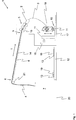
- FIG. 1 shows a schematic side view of an inventive, standing on a hall floor 20, spinning preparation machine 1 in the form of an air spinning machine, which serves to produce roving 3.
- the spinning preparation machine 1 preferably comprises a drafting device 5 with a plurality of corresponding drafting rollers (only one of the two arranged in the entrance of the drafting 5 input rollers 15 is provided with a reference numeral), which with a fiber structure 4, for example in the form of a relined tape, is supplied.
- the fiber structure 4 as a rule comes from a container 7 (eg a spinning can) and is fed to the drafting device 5, preferably after passing a guide roller 21, via a guide 6, wherein the guide 6 can be designed, for example, as an elongated profile.
- the guide 6 comprises a feed section 8 adjacent to the container 7, a dispensing section 9 adjacent to the drafting device 5 and a guide section 14 located therebetween in order to support the fiber structure 4 at least downwards.
- the spinning preparation machine 1 shown comprises a spaced apart from the drafting 5 solidification agent in the form of an air-jet nozzle 2 with an internal, known from the prior art and therefore not shown vortex chamber and a likewise known and therefore also not shown, projecting into the vortex chamber Garnsentelement in shape a hollow spindle.
- the fiber structure 4 or at least part of the fibers of the fiber composite 4 is provided with a protective rotation by means of a vortex air flow generated in the vortex chamber by air nozzles.
- the spinning preparation machine 1 can moreover comprise a draw unit for the roving 3, preferably downstream of the drafting unit 5, in the transport direction T shown, preferably with two draw-off rollers (the withdrawal unit is not absolutely necessary and therefore not shown in the figures). Furthermore, a winding device 10 is provided, which preferably serves to receive at least two sleeves 11 and with the aid of the roving 3 can be wound on a sleeve 11, wherein the roving 3 in this case with the aid of a in the direction of FIG. 1 shown double arrow back and forth movable traversing unit 18 is guided.
- the winding device 10 may in particular comprise a rotatable by means of a drive platform 17 on which the sleeves 11 can be fixed via corresponding, not shown, holding devices, wherein the holding devices and thus the respective sleeves 11, preferably via separate drives in a Rotary movement are offset.
- the spinning preparation machine 1 shown and exemplified as an air-spinning machine operates according to a special air-spinning method.
- the fiber structure 4 is guided in the transport direction T via an inlet opening, not shown, into the swirl chamber of the air-jet nozzle 2.
- a protective rotation d. H. at least a portion of the fibers of the fiber composite 4 is detected by said vortex air flow generated by appropriately positioned spinning air channels.
- a part of the fibers is hereby pulled out of the fiber structure 4 at least a little bit and wound around the tip of the yarn formation element projecting into the vortex chamber.
- the fibers of the fiber composite 4 are withdrawn from the vortex chamber via an inlet opening of the yarn formation element and a withdrawal channel arranged inside the yarn formation element and adjoining the inlet opening.
- the free fiber ends are drawn on a spiral path in the direction of the inlet opening and loop as Umwindefasern to the centrally extending core fibers - resulting in a desired protective rotation having roving.
- the roving 3 has by the only partial rotation of the fibers a delaying ability, which is essential for the further processing of the roving 3 in a subsequent spinning machine, such as a ring spinning machine.
- a subsequent spinning machine such as a ring spinning machine.
- conventional air-spinning devices impart to the fiber structure 4 such a strong rotation that the necessary distortion following the yarn production is no longer possible. This is also desirable in this case, since conventional air spinning machines are designed to produce a finished yarn, which should usually be characterized by a high strength.
- the roving 3 is wound on a sleeve 11 after leaving the air-jet nozzle 2 with the aid of the winding device 10. If the corresponding sleeve 11 sufficiently insufflated with roving 3, it is replaced by an empty sleeve 11, for which purpose said platform 17 is rotated about a preferably vertical axis of rotation until the in FIG. 1 shown empty sleeve 11 in the position the in FIG. 1 shown bespulten sleeve 11 and vice versa.
- a sleeve transfer device 16 is activated, which transfers the spooled sleeve 11 to a transport path 13 (for example in the form of a conveyor belt) a sleeve transport device 12, the sleeve 11 finally to a Transported not shown removal point.
- the corresponding transport path 13, of which several may be present, preferably comprises a plurality of sleeve holders 19, by means of which the sleeves 11 can be held during their transport.
- the winding device 10 could also have only a holding device for a sleeve 11.
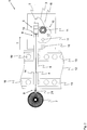
- the transport path (s) 13 in a in FIG. 2 shown plan view of the spinning preparation machine 1 is at least partially disposed between the feed section 8 of the guide 6 and the drafting 5 or are.
- the transport track (s) 13 should in this case be supported in the area of said hall floor 20, so that these are located in the in-hall FIG. 1 shown side view of the spinning preparation machine 1 below the guide 6 is or are located.
- the transport path (s) 13 between the feed section 8 of the guide 6 and the container 7 and the discharge section 9 of the guide 6 is or are arranged, wherein the guide 6 spans the transport path (s) 13 like a bridge ,
- the fiber structure 4 is in this case guided from behind over the transport path (s) 13 and finally arrives in the front area of the spinning preparation machine 1 in the drafting device 5 and finally in the air-spinneret 2.
- the winding device 10, the traversing unit 18, and the sleeve transfer device 16 be arranged laterally of the drafting 5 and the shipsspinndüse 2. In this case, there is a particularly space-saving arrangement of the individual elements.
- the drafting device 5, the air-jet nozzle 2 and also the guide 6 should be placed above the winding device 10, the traversing unit 18, the sleeve transfer device 16 and / or the transport path (s) 13 in order to utilize the clearance above the latter elements.
Landscapes
- Engineering & Computer Science (AREA)
- Mechanical Engineering (AREA)
- Textile Engineering (AREA)
- Spinning Or Twisting Of Yarns (AREA)
Claims (10)
- Machine de préparation de filature (1), comprenant
au moins un moyen de renforcement (2) destiné à produire une mèche (3) comportant une torsion de protection et constitué d'un assemblage de fibres amenées au moyen de renforcement (4),- un banc d'étirage (5) destiné à étirer l'assemblage de fibres (4) avant que celui-ci n'entre dans le moyen de renforcement, le banc d'étirage (5) étant disposé en amont du moyen de renforcement par référence à la direction de transport (L) du banc d'étirage (5) et,- la machine de préparation de filature (1) comportant un dispositif de bobinage (10) destiné à bobiner la mèche (3) sur un bobinot (11), et- la machine de préparation de filature (1) comportant un moyen de transport de bobinot (12) servant à fournir des bobinots vides (11) et/ou pour emporter des bobinots (11) sur lesquels une mèche (3) a été bobinée à l'aide du dispositif de bobinage (10),caractérisée en ce que
la machine de préparation de filature (1) comporte un guide (6) disposé en amont du banc d'étirage (5) par référence à ladite direction de transport (T) et destiné à guider l'assemblage de fibres (4) entre un récipient (7) d'alimentation en l'assemblage de fibres (4) et le banc d'étirage (5), en ce que le guide (6) comporte une section d'alimentation (8) opposée au banc d'étirage (5) et destinée à l'assemblage de fibres (4) provenant d'un récipient (7) pendant le fonctionnement de la machine de préparation de filature (1) et une section de sortie (9) dirigée vers le banc d'étirage (5) et destinée à l'assemblage de fibres (4),
en ce que la machine de préparation de filature (1) comprend un dispositif de transfert de bobinot (16) qui sert à transférer les bobinots (11) d'un moyen de transport de bobinot (12) au dispositif de bobinage (12) et/ou vice versa,
en ce que le dispositif de bobinage (10) et/ou le dispositif de transfert de bobinot (16) sont disposés au moins partiellement au-dessous du guide (6), au-dessous du banc d'étirage (5) et/ou au-dessous du moyen de renforcement,
et en ce que le dispositif de transport de bobinot (12) comporte au moins une bande de transport (13) destinée à transporter des bobinots vides (11) et/ou des bobinots (11) sur lesquels une mèche a été bobinée, la ou les bandes de transport (13) étant disposées, dans une vue de dessus de la machine de préparation de filature (1), au moins partiellement entre la section d'alimentation (8) du guide (6) et le banc d'étirage (5). - Machine de préparation de filature selon la revendication précédente, caractérisée en ce que le moyen de renforcement est conçu comme une filière à air (2), la mèche (3) pourvue de la torsion de protection pouvant être produite à partir de l'assemblage de fibres (4) dans la filière à air (2) à l'aide d'un flux d'air tourbillonnaire.
- Machine de préparation de filature selon l'une des revendications précédentes, caractérisée en ce que la ou les bandes de transport (13) sont prévues, dans une vue de dessus de la machine de préparation de filature (1), au moins partiellement entre la section d'alimentation (8) et la section de sortie (9) du guide (6) et/ou entre la section d'alimentation (8) du guide (6) et le dispositif de bobinage (10) et/ou entre la section d'alimentation (8) du guide (6) et le dispositif de transfert de bobinot (16).
- Machine de préparation de filature selon l'une des revendications précédentes, caractérisée en ce que le guide (6) couvre entièrement, dans une vue de dessus de la machine de préparation de filature (1), une ou plusieurs bandes de transport (13) disposées au-dessous du guide (6), de préférence toute la zone du moyen de transport de bobinot (12) disposée du guide (6) dans ladite vue de dessus.
- Machine de préparation de filature selon l'une des revendications précédentes, caractérisée en ce que la section d'alimentation (8), la section de sortie (9) et/ou une section de guidage intermédiaire (14) du guide (6) et/ou le banc d'étirage (5) et/ou le moyen de renforcement et/ou le dispositif de transfert de bobinot (16) sont disposés, dans une vue latérale de la machine de préparation de filature (1), au-dessus d'au moins une partie de la ou des bandes de transport (13) s'étendant, dans une vue de dessus, entre la section d'alimentation (8) du guide (6) et le banc d'étirage (5).
- Machine de préparation de filature selon l'une des revendications précédentes, caractérisée en ce que le dispositif de bobinage (10) et/ou le dispositif de transfert de bobinot (16) sont disposés, dans une vue de dessus et/ou dans une vue latérale de la machine de préparation de filature (1), au moins partiellement entre la section d'alimentation (8) du guide (6) et le moyen de renforcement et/ou au moins partiellement entre la section d'alimentation (8) du guide (6) et le banc d'étirage (5).
- Machine de préparation de filature selon l'une des revendications précédentes, caractérisée en ce que la section d'alimentation (8) du guide (6) est espacée, dans la direction horizontale, d'au moins 50 cm, de préférence d'au moins 100 cm, de manière particulièrement préférée d'au moins 150 cm, d'un rouleau d'entrée (15) du banc d'étirage (5).
- Machine de préparation de filature selon l'une des revendications précédentes, caractérisée en ce que le banc d'étirage (5) et le guide (6) et/ou le banc d'étirage (5) et le dispositif de bobinage (10) et/ou le banc d'étirage (5) et le dispositif de transfert de bobinot (16) sont disposés, dans une vue latérale de la machine de préparation de filature (1), du même côté du moyen de renforcement dans la direction horizontale.
- Machine de préparation de filature selon l'une des revendications précédentes, caractérisée en ce que le dispositif de bobinage (10), le dispositif de transfert de bobinot (16), le banc d'étirage (5), le guide (6) et/ou la ou les bandes de transport (13) sont disposés, dans une vue frontale de la machine de préparation de filature (1), au moins partiellement en arrière du moyen de renforcement.
- Machine de préparation de filature selon l'une des revendications précédentes, caractérisée en ce que la section d'alimentation (8) est disposée, dans une vue frontale de la machine de préparation de filature (1), en arrière du banc d'étirage (5), en arrière de la section de sortie (9) du guide (6), en arrière du dispositif de bobinage (10), en arrière du dispositif de transfert de bobinot {16), en arrière d'au moins une bande de transport (13) et/ou en arrière de tout le moyen de transport de bobinot (12) qui s'étend au-dessous du guide (6).
Applications Claiming Priority (2)
| Application Number | Priority Date | Filing Date | Title |
|---|---|---|---|
| CH00796/14A CH709692A1 (de) | 2014-05-26 | 2014-05-26 | Spinnereivorbereitungsmaschine mit Hülsentransporteinrichtung. |
| PCT/IB2015/000662 WO2015181600A1 (fr) | 2014-05-26 | 2015-05-11 | Machine de préparation de filature |
Publications (2)
| Publication Number | Publication Date |
|---|---|
| EP3149230A1 EP3149230A1 (fr) | 2017-04-05 |
| EP3149230B1 true EP3149230B1 (fr) | 2018-04-18 |
Family
ID=53510918
Family Applications (1)
| Application Number | Title | Priority Date | Filing Date |
|---|---|---|---|
| EP15733881.5A Not-in-force EP3149230B1 (fr) | 2014-05-26 | 2015-05-11 | Machine de préparation de filature |
Country Status (7)
| Country | Link |
|---|---|
| US (1) | US10329693B2 (fr) |
| EP (1) | EP3149230B1 (fr) |
| JP (1) | JP2017519911A (fr) |
| CN (1) | CN106460248B (fr) |
| CH (1) | CH709692A1 (fr) |
| TR (1) | TR201809464T4 (fr) |
| WO (1) | WO2015181600A1 (fr) |
Families Citing this family (2)
| Publication number | Priority date | Publication date | Assignee | Title |
|---|---|---|---|---|
| CH709605A1 (de) * | 2014-05-08 | 2015-11-13 | Rieter Ag Maschf | Textilmaschine zur Herstellung von Vorgarn sowie Verfahren zum Betrieb einer entsprechenden Textilmaschine. |
| CN110907245B (zh) * | 2019-12-04 | 2022-04-19 | 河北科技大学 | 小定量棉纤维卷绕制样装置 |
Family Cites Families (22)
| Publication number | Priority date | Publication date | Assignee | Title |
|---|---|---|---|---|
| USRE30162E (en) * | 1973-12-26 | 1979-12-11 | Kabushiki Kaisha Toyoda Jidoshokki Seisakusho | Method and device for transferring fresh bobbins from a bobbin supply device to a conveyor belt of a textile machine |
| JPS50123943A (fr) * | 1974-03-25 | 1975-09-29 | ||
| DE2447715C3 (de) | 1974-10-07 | 1978-09-07 | Hoechst Ag, 6000 Frankfurt | Vorgarn und Verfahren zu dessen Herstellung |
| JPS5526053U (fr) * | 1978-08-07 | 1980-02-20 | ||
| CH641217A5 (de) * | 1979-10-29 | 1984-02-15 | Zellweger Uster Ag | Verfahren und vorrichtung zum sortieren von spinnkoerpern auf spinnmaschinen. |
| JPS5982433A (ja) * | 1982-11-02 | 1984-05-12 | Toyoda Autom Loom Works Ltd | 粗紡機における管替え方法及びその装置 |
| CS264580B1 (en) * | 1987-09-02 | 1989-08-14 | Burysek Frantisek | Equipment for textile machine tube supply |
| JPH01110277U (fr) * | 1988-01-14 | 1989-07-25 | ||
| DE3908462A1 (de) * | 1988-08-11 | 1990-02-15 | Fritz Stahlecker | Spinnmaschine mit spulenwechslern |
| DE3831639A1 (de) * | 1988-09-17 | 1990-03-22 | Schlafhorst & Co W | Verfahren und vorrichtung zur versorgung der spinnstellen eines spinnautomaten mit faserband |
| EP0410015B1 (fr) * | 1989-07-24 | 1993-11-18 | Palitex Project-Company GmbH | Procédé et dispositif pour l'extraction automatique d'un adaptateur pour bobines et pour transport d'un poste de traitement de fil, en particulier d'un pot d'une broche à retordre à double torsion |
| DE3936518C2 (de) * | 1989-11-02 | 2001-10-11 | Rieter Ag Maschf | Vorspinnmaschine |
| US5222350A (en) * | 1990-12-06 | 1993-06-29 | Platt Saco Lowell Corporation | Roving frame and method |
| JPH0510478U (ja) * | 1991-07-23 | 1993-02-09 | 村田機械株式会社 | 長繊維紡績機 |
| DE4445265C2 (de) * | 1994-12-19 | 1997-02-20 | Zinser Textilmaschinen Gmbh | Transport- und Umsetzsystem für Vorgarnspulen und leere Hülsen |
| DE19505050C2 (de) * | 1995-02-15 | 1997-01-23 | Zinser Textilmaschinen Gmbh | Transport- und Umsetzsystem zwischen mindestens einer Vorspinnmaschine und einem nachgeordneten Lager- oder Verarbeitungsbereich |
| WO2005026420A1 (fr) * | 2003-09-12 | 2005-03-24 | Maschinenfabrik Rieter Ag | Ensemble banc d'etirage-banc a broches permettant de produire une meche par un procede de filage pneumatique |
| ATE391197T1 (de) * | 2004-12-01 | 2008-04-15 | Rovira Trias Juan | Vorspinnmaschine zur herstellung und lieferung von vorgarnspulen |
| DE102006024553B4 (de) * | 2006-05-23 | 2008-05-08 | Oerlikon Textile Gmbh & Co. Kg | Vorspinnmaschine mit selbstständiger Spulenwechselvorrichtung |
| EP1870500B1 (fr) * | 2006-06-22 | 2011-05-18 | Rieter Ingolstadt GmbH | Banc d'étirage d'une machine de prétraitement de filature |
| WO2009086646A1 (fr) | 2008-01-11 | 2009-07-16 | Maschinenfabrik Rieter Ag | Procédé de fabrication d'une mèche |
| DE102012102695A1 (de) * | 2012-03-29 | 2013-10-02 | Maschinenfabrik Rieter Ag | Vorspinnmaschine mit einer Anordnung zur Detektion und Entfernung von Garnfehlern |
-
2014
- 2014-05-26 CH CH00796/14A patent/CH709692A1/de not_active Application Discontinuation
-
2015
- 2015-05-11 TR TR2018/09464T patent/TR201809464T4/tr unknown
- 2015-05-11 WO PCT/IB2015/000662 patent/WO2015181600A1/fr not_active Ceased
- 2015-05-11 CN CN201580027773.1A patent/CN106460248B/zh not_active Expired - Fee Related
- 2015-05-11 EP EP15733881.5A patent/EP3149230B1/fr not_active Not-in-force
- 2015-05-11 JP JP2016569749A patent/JP2017519911A/ja not_active Ceased
- 2015-05-11 US US15/313,418 patent/US10329693B2/en not_active Expired - Fee Related
Non-Patent Citations (1)
| Title |
|---|
| None * |
Also Published As
| Publication number | Publication date |
|---|---|
| JP2017519911A (ja) | 2017-07-20 |
| US20170096752A1 (en) | 2017-04-06 |
| WO2015181600A1 (fr) | 2015-12-03 |
| EP3149230A1 (fr) | 2017-04-05 |
| CN106460248A (zh) | 2017-02-22 |
| CN106460248B (zh) | 2019-07-26 |
| US10329693B2 (en) | 2019-06-25 |
| CH709692A1 (de) | 2015-11-30 |
| TR201809464T4 (tr) | 2018-07-23 |
Similar Documents
| Publication | Publication Date | Title |
|---|---|---|
| EP3148913B1 (fr) | Procédé permettant de faire fonctionner une machine textile et machine textile servant à produire une mèche | |
| EP2147137B1 (fr) | Dispositif de filage par fusion et de bobinage de fils synthétiques | |
| EP3140440B1 (fr) | Machine textile et procédé pour faire fonctionner une telle machine | |
| DE19815053A1 (de) | Verfahren zum Herstellen eines Scheinzwirnes und Spinnmaschine hierfür | |
| DE3943600C2 (de) | Verfahren und Vorrichtung zur Herstellung eines Mehrfachfadens sowie Mehrfachfaden | |
| DE2350558B2 (de) | Zieh-texturiermaschine | |
| EP2358932B1 (fr) | Dispositif pour texturer et enrouler plusieurs fils | |
| DE10236450A1 (de) | Spinnmaschine mit einem Mehrstufen-Verdichtungs-Streckwerk | |
| DE3926227C2 (fr) | ||
| EP3149229B1 (fr) | Machine de préparation de filature | |
| EP2980284B1 (fr) | Procede de fabrication d'un fil produit par jet d'air | |
| EP3140232B1 (fr) | Machine textile servant à la production de mèche et procédé pour faire fonctionner une telle machine textile | |
| WO2015181600A1 (fr) | Machine de préparation de filature | |
| CH713018A1 (de) | Vorspinnmaschine sowie Verfahren zur Produktion von Vorgarn. | |
| EP3484801B1 (fr) | Procédé de traitement d'un assemblage de fibres en forme de toron ainsi que banc à broches | |
| EP3140233B1 (fr) | Machine textile pour la production d'une meche et procede de demarrage d'une telle machine pour produire une meche | |
| DE1943658A1 (de) | Verfahren und Vorrichtung zur kontinuierlichen Herstellung einer Vielzahl von synthetischen Faeden,insbesondere von Polyamid- oder Polyesterfaeden | |
| DE10214479A1 (de) | Verfahren und Vorrichtung zur Herstellung von Stapelfasern | |
| CH713502A2 (de) | Luftspinnmaschine zur Herstellung eines Garns aus einem strangförmigen Faserverband. | |
| CH713501A2 (de) | Luftspinnmaschine zur Herstellung eines Garns aus einem strangförmigen Faserverband. | |
| DE4127490A1 (de) | Ringspinnmaschine |
Legal Events
| Date | Code | Title | Description |
|---|---|---|---|
| PUAI | Public reference made under article 153(3) epc to a published international application that has entered the european phase |
Free format text: ORIGINAL CODE: 0009012 |
|
| 17P | Request for examination filed |
Effective date: 20161125 |
|
| AK | Designated contracting states |
Kind code of ref document: A1 Designated state(s): AL AT BE BG CH CY CZ DE DK EE ES FI FR GB GR HR HU IE IS IT LI LT LU LV MC MK MT NL NO PL PT RO RS SE SI SK SM TR |
|
| AX | Request for extension of the european patent |
Extension state: BA ME |
|
| DAV | Request for validation of the european patent (deleted) | ||
| DAX | Request for extension of the european patent (deleted) | ||
| GRAP | Despatch of communication of intention to grant a patent |
Free format text: ORIGINAL CODE: EPIDOSNIGR1 |
|
| INTG | Intention to grant announced |
Effective date: 20180105 |
|
| RIN1 | Information on inventor provided before grant (corrected) |
Inventor name: HASKA, PETR Inventor name: GRIESSHAMMER, CHRISTIAN |
|
| GRAS | Grant fee paid |
Free format text: ORIGINAL CODE: EPIDOSNIGR3 |
|
| GRAA | (expected) grant |
Free format text: ORIGINAL CODE: 0009210 |
|
| AK | Designated contracting states |
Kind code of ref document: B1 Designated state(s): AL AT BE BG CH CY CZ DE DK EE ES FI FR GB GR HR HU IE IS IT LI LT LU LV MC MK MT NL NO PL PT RO RS SE SI SK SM TR |
|
| REG | Reference to a national code |
Ref country code: GB Ref legal event code: FG4D Free format text: NOT ENGLISH |
|
| REG | Reference to a national code |
Ref country code: CH Ref legal event code: EP |
|
| REG | Reference to a national code |
Ref country code: AT Ref legal event code: REF Ref document number: 990580 Country of ref document: AT Kind code of ref document: T Effective date: 20180515 |
|
| REG | Reference to a national code |
Ref country code: IE Ref legal event code: FG4D Free format text: LANGUAGE OF EP DOCUMENT: GERMAN |
|
| REG | Reference to a national code |
Ref country code: DE Ref legal event code: R096 Ref document number: 502015003948 Country of ref document: DE |
|
| REG | Reference to a national code |
Ref country code: NL Ref legal event code: MP Effective date: 20180418 |
|
| REG | Reference to a national code |
Ref country code: LT Ref legal event code: MG4D |
|
| PG25 | Lapsed in a contracting state [announced via postgrant information from national office to epo] |
Ref country code: NL Free format text: LAPSE BECAUSE OF FAILURE TO SUBMIT A TRANSLATION OF THE DESCRIPTION OR TO PAY THE FEE WITHIN THE PRESCRIBED TIME-LIMIT Effective date: 20180418 |
|
| PG25 | Lapsed in a contracting state [announced via postgrant information from national office to epo] |
Ref country code: BG Free format text: LAPSE BECAUSE OF FAILURE TO SUBMIT A TRANSLATION OF THE DESCRIPTION OR TO PAY THE FEE WITHIN THE PRESCRIBED TIME-LIMIT Effective date: 20180718 Ref country code: FI Free format text: LAPSE BECAUSE OF FAILURE TO SUBMIT A TRANSLATION OF THE DESCRIPTION OR TO PAY THE FEE WITHIN THE PRESCRIBED TIME-LIMIT Effective date: 20180418 Ref country code: AL Free format text: LAPSE BECAUSE OF FAILURE TO SUBMIT A TRANSLATION OF THE DESCRIPTION OR TO PAY THE FEE WITHIN THE PRESCRIBED TIME-LIMIT Effective date: 20180418 Ref country code: NO Free format text: LAPSE BECAUSE OF FAILURE TO SUBMIT A TRANSLATION OF THE DESCRIPTION OR TO PAY THE FEE WITHIN THE PRESCRIBED TIME-LIMIT Effective date: 20180718 Ref country code: PL Free format text: LAPSE BECAUSE OF FAILURE TO SUBMIT A TRANSLATION OF THE DESCRIPTION OR TO PAY THE FEE WITHIN THE PRESCRIBED TIME-LIMIT Effective date: 20180418 Ref country code: SE Free format text: LAPSE BECAUSE OF FAILURE TO SUBMIT A TRANSLATION OF THE DESCRIPTION OR TO PAY THE FEE WITHIN THE PRESCRIBED TIME-LIMIT Effective date: 20180418 Ref country code: LT Free format text: LAPSE BECAUSE OF FAILURE TO SUBMIT A TRANSLATION OF THE DESCRIPTION OR TO PAY THE FEE WITHIN THE PRESCRIBED TIME-LIMIT Effective date: 20180418 Ref country code: ES Free format text: LAPSE BECAUSE OF FAILURE TO SUBMIT A TRANSLATION OF THE DESCRIPTION OR TO PAY THE FEE WITHIN THE PRESCRIBED TIME-LIMIT Effective date: 20180418 |
|
| PG25 | Lapsed in a contracting state [announced via postgrant information from national office to epo] |
Ref country code: HR Free format text: LAPSE BECAUSE OF FAILURE TO SUBMIT A TRANSLATION OF THE DESCRIPTION OR TO PAY THE FEE WITHIN THE PRESCRIBED TIME-LIMIT Effective date: 20180418 Ref country code: RS Free format text: LAPSE BECAUSE OF FAILURE TO SUBMIT A TRANSLATION OF THE DESCRIPTION OR TO PAY THE FEE WITHIN THE PRESCRIBED TIME-LIMIT Effective date: 20180418 Ref country code: GR Free format text: LAPSE BECAUSE OF FAILURE TO SUBMIT A TRANSLATION OF THE DESCRIPTION OR TO PAY THE FEE WITHIN THE PRESCRIBED TIME-LIMIT Effective date: 20180719 Ref country code: LV Free format text: LAPSE BECAUSE OF FAILURE TO SUBMIT A TRANSLATION OF THE DESCRIPTION OR TO PAY THE FEE WITHIN THE PRESCRIBED TIME-LIMIT Effective date: 20180418 |
|
| REG | Reference to a national code |
Ref country code: CH Ref legal event code: PL |
|
| REG | Reference to a national code |
Ref country code: DE Ref legal event code: R097 Ref document number: 502015003948 Country of ref document: DE |
|
| REG | Reference to a national code |
Ref country code: BE Ref legal event code: MM Effective date: 20180531 |
|
| PG25 | Lapsed in a contracting state [announced via postgrant information from national office to epo] |
Ref country code: RO Free format text: LAPSE BECAUSE OF FAILURE TO SUBMIT A TRANSLATION OF THE DESCRIPTION OR TO PAY THE FEE WITHIN THE PRESCRIBED TIME-LIMIT Effective date: 20180418 Ref country code: SK Free format text: LAPSE BECAUSE OF FAILURE TO SUBMIT A TRANSLATION OF THE DESCRIPTION OR TO PAY THE FEE WITHIN THE PRESCRIBED TIME-LIMIT Effective date: 20180418 Ref country code: EE Free format text: LAPSE BECAUSE OF FAILURE TO SUBMIT A TRANSLATION OF THE DESCRIPTION OR TO PAY THE FEE WITHIN THE PRESCRIBED TIME-LIMIT Effective date: 20180418 Ref country code: DK Free format text: LAPSE BECAUSE OF FAILURE TO SUBMIT A TRANSLATION OF THE DESCRIPTION OR TO PAY THE FEE WITHIN THE PRESCRIBED TIME-LIMIT Effective date: 20180418 Ref country code: MC Free format text: LAPSE BECAUSE OF FAILURE TO SUBMIT A TRANSLATION OF THE DESCRIPTION OR TO PAY THE FEE WITHIN THE PRESCRIBED TIME-LIMIT Effective date: 20180418 |
|
| REG | Reference to a national code |
Ref country code: IE Ref legal event code: MM4A |
|
| PLBE | No opposition filed within time limit |
Free format text: ORIGINAL CODE: 0009261 |
|
| STAA | Information on the status of an ep patent application or granted ep patent |
Free format text: STATUS: NO OPPOSITION FILED WITHIN TIME LIMIT |
|
| PG25 | Lapsed in a contracting state [announced via postgrant information from national office to epo] |
Ref country code: SM Free format text: LAPSE BECAUSE OF FAILURE TO SUBMIT A TRANSLATION OF THE DESCRIPTION OR TO PAY THE FEE WITHIN THE PRESCRIBED TIME-LIMIT Effective date: 20180418 Ref country code: LI Free format text: LAPSE BECAUSE OF NON-PAYMENT OF DUE FEES Effective date: 20180531 Ref country code: CH Free format text: LAPSE BECAUSE OF NON-PAYMENT OF DUE FEES Effective date: 20180531 |
|
| 26N | No opposition filed |
Effective date: 20190121 |
|
| PG25 | Lapsed in a contracting state [announced via postgrant information from national office to epo] |
Ref country code: LU Free format text: LAPSE BECAUSE OF NON-PAYMENT OF DUE FEES Effective date: 20180511 |
|
| PG25 | Lapsed in a contracting state [announced via postgrant information from national office to epo] |
Ref country code: FR Free format text: LAPSE BECAUSE OF NON-PAYMENT OF DUE FEES Effective date: 20180618 Ref country code: IE Free format text: LAPSE BECAUSE OF NON-PAYMENT OF DUE FEES Effective date: 20180511 |
|
| PG25 | Lapsed in a contracting state [announced via postgrant information from national office to epo] |
Ref country code: BE Free format text: LAPSE BECAUSE OF NON-PAYMENT OF DUE FEES Effective date: 20180531 Ref country code: SI Free format text: LAPSE BECAUSE OF FAILURE TO SUBMIT A TRANSLATION OF THE DESCRIPTION OR TO PAY THE FEE WITHIN THE PRESCRIBED TIME-LIMIT Effective date: 20180418 |
|
| GBPC | Gb: european patent ceased through non-payment of renewal fee |
Effective date: 20190511 |
|
| PG25 | Lapsed in a contracting state [announced via postgrant information from national office to epo] |
Ref country code: MT Free format text: LAPSE BECAUSE OF FAILURE TO SUBMIT A TRANSLATION OF THE DESCRIPTION OR TO PAY THE FEE WITHIN THE PRESCRIBED TIME-LIMIT Effective date: 20180418 |
|
| PG25 | Lapsed in a contracting state [announced via postgrant information from national office to epo] |
Ref country code: GB Free format text: LAPSE BECAUSE OF NON-PAYMENT OF DUE FEES Effective date: 20190511 |
|
| PG25 | Lapsed in a contracting state [announced via postgrant information from national office to epo] |
Ref country code: PT Free format text: LAPSE BECAUSE OF FAILURE TO SUBMIT A TRANSLATION OF THE DESCRIPTION OR TO PAY THE FEE WITHIN THE PRESCRIBED TIME-LIMIT Effective date: 20180418 |
|
| PG25 | Lapsed in a contracting state [announced via postgrant information from national office to epo] |
Ref country code: HU Free format text: LAPSE BECAUSE OF FAILURE TO SUBMIT A TRANSLATION OF THE DESCRIPTION OR TO PAY THE FEE WITHIN THE PRESCRIBED TIME-LIMIT; INVALID AB INITIO Effective date: 20150511 Ref country code: MK Free format text: LAPSE BECAUSE OF NON-PAYMENT OF DUE FEES Effective date: 20180418 Ref country code: CY Free format text: LAPSE BECAUSE OF FAILURE TO SUBMIT A TRANSLATION OF THE DESCRIPTION OR TO PAY THE FEE WITHIN THE PRESCRIBED TIME-LIMIT Effective date: 20180418 |
|
| PG25 | Lapsed in a contracting state [announced via postgrant information from national office to epo] |
Ref country code: IS Free format text: LAPSE BECAUSE OF FAILURE TO SUBMIT A TRANSLATION OF THE DESCRIPTION OR TO PAY THE FEE WITHIN THE PRESCRIBED TIME-LIMIT Effective date: 20180818 |
|
| PGFP | Annual fee paid to national office [announced via postgrant information from national office to epo] |
Ref country code: CZ Payment date: 20200511 Year of fee payment: 6 Ref country code: DE Payment date: 20200520 Year of fee payment: 6 Ref country code: TR Payment date: 20200511 Year of fee payment: 6 |
|
| PGFP | Annual fee paid to national office [announced via postgrant information from national office to epo] |
Ref country code: IT Payment date: 20200528 Year of fee payment: 6 |
|
| REG | Reference to a national code |
Ref country code: AT Ref legal event code: MM01 Ref document number: 990580 Country of ref document: AT Kind code of ref document: T Effective date: 20200511 |
|
| PG25 | Lapsed in a contracting state [announced via postgrant information from national office to epo] |
Ref country code: AT Free format text: LAPSE BECAUSE OF NON-PAYMENT OF DUE FEES Effective date: 20200511 |
|
| REG | Reference to a national code |
Ref country code: DE Ref legal event code: R119 Ref document number: 502015003948 Country of ref document: DE |
|
| PG25 | Lapsed in a contracting state [announced via postgrant information from national office to epo] |
Ref country code: CZ Free format text: LAPSE BECAUSE OF NON-PAYMENT OF DUE FEES Effective date: 20210511 |
|
| PG25 | Lapsed in a contracting state [announced via postgrant information from national office to epo] |
Ref country code: DE Free format text: LAPSE BECAUSE OF NON-PAYMENT OF DUE FEES Effective date: 20211201 |
|
| PG25 | Lapsed in a contracting state [announced via postgrant information from national office to epo] |
Ref country code: TR Free format text: LAPSE BECAUSE OF NON-PAYMENT OF DUE FEES Effective date: 20210511 |
|
| PG25 | Lapsed in a contracting state [announced via postgrant information from national office to epo] |
Ref country code: IT Free format text: LAPSE BECAUSE OF NON-PAYMENT OF DUE FEES Effective date: 20200511 |
|
| PG25 | Lapsed in a contracting state [announced via postgrant information from national office to epo] |
Ref country code: IT Free format text: LAPSE BECAUSE OF NON-PAYMENT OF DUE FEES Effective date: 20210511 |