EP3149244B1 - Heizvorrichtung und verfahren zum entfrosten des bodens - Google Patents
Heizvorrichtung und verfahren zum entfrosten des bodens Download PDFInfo
- Publication number
- EP3149244B1 EP3149244B1 EP15799242.1A EP15799242A EP3149244B1 EP 3149244 B1 EP3149244 B1 EP 3149244B1 EP 15799242 A EP15799242 A EP 15799242A EP 3149244 B1 EP3149244 B1 EP 3149244B1
- Authority
- EP
- European Patent Office
- Prior art keywords
- heat
- thaw
- coils
- heat pump
- heating device
- Prior art date
- Legal status (The legal status is an assumption and is not a legal conclusion. Google has not performed a legal analysis and makes no representation as to the accuracy of the status listed.)
- Active
Links
Images



Classifications
-
- F—MECHANICAL ENGINEERING; LIGHTING; HEATING; WEAPONS; BLASTING
- F24—HEATING; RANGES; VENTILATING
- F24T—GEOTHERMAL COLLECTORS; GEOTHERMAL SYSTEMS
- F24T10/00—Geothermal collectors
- F24T10/10—Geothermal collectors with circulation of working fluids through underground channels, the working fluids not coming into direct contact with the ground
-
- E—FIXED CONSTRUCTIONS
- E01—CONSTRUCTION OF ROADS, RAILWAYS, OR BRIDGES
- E01C—CONSTRUCTION OF, OR SURFACES FOR, ROADS, SPORTS GROUNDS, OR THE LIKE; MACHINES OR AUXILIARY TOOLS FOR CONSTRUCTION OR REPAIR
- E01C11/00—Details of pavings
- E01C11/24—Methods or arrangements for preventing slipperiness or protecting against influences of the weather
-
- E—FIXED CONSTRUCTIONS
- E01—CONSTRUCTION OF ROADS, RAILWAYS, OR BRIDGES
- E01C—CONSTRUCTION OF, OR SURFACES FOR, ROADS, SPORTS GROUNDS, OR THE LIKE; MACHINES OR AUXILIARY TOOLS FOR CONSTRUCTION OR REPAIR
- E01C11/00—Details of pavings
- E01C11/24—Methods or arrangements for preventing slipperiness or protecting against influences of the weather
- E01C11/26—Permanently installed heating or blowing devices ; Mounting thereof
-
- E—FIXED CONSTRUCTIONS
- E01—CONSTRUCTION OF ROADS, RAILWAYS, OR BRIDGES
- E01C—CONSTRUCTION OF, OR SURFACES FOR, ROADS, SPORTS GROUNDS, OR THE LIKE; MACHINES OR AUXILIARY TOOLS FOR CONSTRUCTION OR REPAIR
- E01C13/00—Pavings or foundations specially adapted for playgrounds or sports grounds; Drainage, irrigation or heating of sports grounds
- E01C13/08—Surfaces simulating grass ; Grass-grown sports grounds
- E01C13/083—Construction of grass-grown sports grounds; Drainage, irrigation or heating arrangements therefor
-
- F—MECHANICAL ENGINEERING; LIGHTING; HEATING; WEAPONS; BLASTING
- F24—HEATING; RANGES; VENTILATING
- F24D—DOMESTIC- OR SPACE-HEATING SYSTEMS, e.g. CENTRAL HEATING SYSTEMS; DOMESTIC HOT-WATER SUPPLY SYSTEMS; ELEMENTS OR COMPONENTS THEREFOR
- F24D3/00—Hot-water central heating systems
- F24D3/18—Hot-water central heating systems using heat pumps
-
- F—MECHANICAL ENGINEERING; LIGHTING; HEATING; WEAPONS; BLASTING
- F25—REFRIGERATION OR COOLING; COMBINED HEATING AND REFRIGERATION SYSTEMS; HEAT PUMP SYSTEMS; MANUFACTURE OR STORAGE OF ICE; LIQUEFACTION SOLIDIFICATION OF GASES
- F25B—REFRIGERATION MACHINES, PLANTS OR SYSTEMS; COMBINED HEATING AND REFRIGERATION SYSTEMS; HEAT PUMP SYSTEMS
- F25B30/00—Heat pumps
- F25B30/06—Heat pumps characterised by the source of low potential heat
-
- E—FIXED CONSTRUCTIONS
- E01—CONSTRUCTION OF ROADS, RAILWAYS, OR BRIDGES
- E01C—CONSTRUCTION OF, OR SURFACES FOR, ROADS, SPORTS GROUNDS, OR THE LIKE; MACHINES OR AUXILIARY TOOLS FOR CONSTRUCTION OR REPAIR
- E01C11/00—Details of pavings
- E01C11/24—Methods or arrangements for preventing slipperiness or protecting against influences of the weather
- E01C11/245—Methods or arrangements for preventing slipperiness or protecting against influences of the weather for preventing ice formation or for loosening ice, e.g. special additives to the paving material, resilient coatings
-
- F—MECHANICAL ENGINEERING; LIGHTING; HEATING; WEAPONS; BLASTING
- F24—HEATING; RANGES; VENTILATING
- F24D—DOMESTIC- OR SPACE-HEATING SYSTEMS, e.g. CENTRAL HEATING SYSTEMS; DOMESTIC HOT-WATER SUPPLY SYSTEMS; ELEMENTS OR COMPONENTS THEREFOR
- F24D2200/00—Heat sources or energy sources
- F24D2200/11—Geothermal energy
-
- F—MECHANICAL ENGINEERING; LIGHTING; HEATING; WEAPONS; BLASTING
- F24—HEATING; RANGES; VENTILATING
- F24D—DOMESTIC- OR SPACE-HEATING SYSTEMS, e.g. CENTRAL HEATING SYSTEMS; DOMESTIC HOT-WATER SUPPLY SYSTEMS; ELEMENTS OR COMPONENTS THEREFOR
- F24D2200/00—Heat sources or energy sources
- F24D2200/14—Solar energy
-
- F—MECHANICAL ENGINEERING; LIGHTING; HEATING; WEAPONS; BLASTING
- F25—REFRIGERATION OR COOLING; COMBINED HEATING AND REFRIGERATION SYSTEMS; HEAT PUMP SYSTEMS; MANUFACTURE OR STORAGE OF ICE; LIQUEFACTION SOLIDIFICATION OF GASES
- F25B—REFRIGERATION MACHINES, PLANTS OR SYSTEMS; COMBINED HEATING AND REFRIGERATION SYSTEMS; HEAT PUMP SYSTEMS
- F25B2339/00—Details of evaporators; Details of condensers
- F25B2339/04—Details of condensers
- F25B2339/047—Water-cooled condensers
-
- F—MECHANICAL ENGINEERING; LIGHTING; HEATING; WEAPONS; BLASTING
- F25—REFRIGERATION OR COOLING; COMBINED HEATING AND REFRIGERATION SYSTEMS; HEAT PUMP SYSTEMS; MANUFACTURE OR STORAGE OF ICE; LIQUEFACTION SOLIDIFICATION OF GASES
- F25B—REFRIGERATION MACHINES, PLANTS OR SYSTEMS; COMBINED HEATING AND REFRIGERATION SYSTEMS; HEAT PUMP SYSTEMS
- F25B25/00—Machines, plants or systems, using a combination of modes of operation covered by two or more of the groups F25B1/00 - F25B23/00
- F25B25/005—Machines, plants or systems, using a combination of modes of operation covered by two or more of the groups F25B1/00 - F25B23/00 using primary and secondary systems
-
- Y—GENERAL TAGGING OF NEW TECHNOLOGICAL DEVELOPMENTS; GENERAL TAGGING OF CROSS-SECTIONAL TECHNOLOGIES SPANNING OVER SEVERAL SECTIONS OF THE IPC; TECHNICAL SUBJECTS COVERED BY FORMER USPC CROSS-REFERENCE ART COLLECTIONS [XRACs] AND DIGESTS
- Y02—TECHNOLOGIES OR APPLICATIONS FOR MITIGATION OR ADAPTATION AGAINST CLIMATE CHANGE
- Y02B—CLIMATE CHANGE MITIGATION TECHNOLOGIES RELATED TO BUILDINGS, e.g. HOUSING, HOUSE APPLIANCES OR RELATED END-USER APPLICATIONS
- Y02B10/00—Integration of renewable energy sources in buildings
- Y02B10/20—Solar thermal
-
- Y—GENERAL TAGGING OF NEW TECHNOLOGICAL DEVELOPMENTS; GENERAL TAGGING OF CROSS-SECTIONAL TECHNOLOGIES SPANNING OVER SEVERAL SECTIONS OF THE IPC; TECHNICAL SUBJECTS COVERED BY FORMER USPC CROSS-REFERENCE ART COLLECTIONS [XRACs] AND DIGESTS
- Y02—TECHNOLOGIES OR APPLICATIONS FOR MITIGATION OR ADAPTATION AGAINST CLIMATE CHANGE
- Y02B—CLIMATE CHANGE MITIGATION TECHNOLOGIES RELATED TO BUILDINGS, e.g. HOUSING, HOUSE APPLIANCES OR RELATED END-USER APPLICATIONS
- Y02B10/00—Integration of renewable energy sources in buildings
- Y02B10/40—Geothermal heat-pumps
-
- Y—GENERAL TAGGING OF NEW TECHNOLOGICAL DEVELOPMENTS; GENERAL TAGGING OF CROSS-SECTIONAL TECHNOLOGIES SPANNING OVER SEVERAL SECTIONS OF THE IPC; TECHNICAL SUBJECTS COVERED BY FORMER USPC CROSS-REFERENCE ART COLLECTIONS [XRACs] AND DIGESTS
- Y02—TECHNOLOGIES OR APPLICATIONS FOR MITIGATION OR ADAPTATION AGAINST CLIMATE CHANGE
- Y02B—CLIMATE CHANGE MITIGATION TECHNOLOGIES RELATED TO BUILDINGS, e.g. HOUSING, HOUSE APPLIANCES OR RELATED END-USER APPLICATIONS
- Y02B10/00—Integration of renewable energy sources in buildings
- Y02B10/70—Hybrid systems, e.g. uninterruptible or back-up power supplies integrating renewable energies
-
- Y—GENERAL TAGGING OF NEW TECHNOLOGICAL DEVELOPMENTS; GENERAL TAGGING OF CROSS-SECTIONAL TECHNOLOGIES SPANNING OVER SEVERAL SECTIONS OF THE IPC; TECHNICAL SUBJECTS COVERED BY FORMER USPC CROSS-REFERENCE ART COLLECTIONS [XRACs] AND DIGESTS
- Y02—TECHNOLOGIES OR APPLICATIONS FOR MITIGATION OR ADAPTATION AGAINST CLIMATE CHANGE
- Y02B—CLIMATE CHANGE MITIGATION TECHNOLOGIES RELATED TO BUILDINGS, e.g. HOUSING, HOUSE APPLIANCES OR RELATED END-USER APPLICATIONS
- Y02B30/00—Energy efficient heating, ventilation or air conditioning [HVAC]
- Y02B30/12—Hot water central heating systems using heat pumps
-
- Y—GENERAL TAGGING OF NEW TECHNOLOGICAL DEVELOPMENTS; GENERAL TAGGING OF CROSS-SECTIONAL TECHNOLOGIES SPANNING OVER SEVERAL SECTIONS OF THE IPC; TECHNICAL SUBJECTS COVERED BY FORMER USPC CROSS-REFERENCE ART COLLECTIONS [XRACs] AND DIGESTS
- Y02—TECHNOLOGIES OR APPLICATIONS FOR MITIGATION OR ADAPTATION AGAINST CLIMATE CHANGE
- Y02E—REDUCTION OF GREENHOUSE GAS [GHG] EMISSIONS, RELATED TO ENERGY GENERATION, TRANSMISSION OR DISTRIBUTION
- Y02E10/00—Energy generation through renewable energy sources
- Y02E10/10—Geothermal energy
Definitions
- the present invention relates generally to a heating device and a method for thawing ground.
- a drawback of the known art is that thawing is energy consuming.
- the melting heat for ice is high (80 cal/gram) and frozen ground, especially at a high water content therefore requires also much energy for thawing, in addition to the ice and snow that may lay on the ground surface. If, at the same time, the weather is cold, much energy is lost to the surroundings. This is reinforced by wind and a relatively high humidity.
- An object of the present invention is to alleviate some of the disadvantages of the prior art and to provide a heating device and a method which enable the thawing of ground in an energy efficient manner.
- a heating device comprising an energy well, a heat pump which is adapted to take up and transfer heat from the energy well by the aid of a line from the energy well to the heat pump for transport of anti-freeze liquid, a heat extraction device connected to the heat pump which selectively can be brought into a connected and a disconnected position, thaw coils for thawing ground surrounding the thaw coils, in which the anti-freeze liquid is transportable, which thaw coils selectively can be connected and disconnected to the line from the energy well to the heat pump, a heat exchanger connected to the heat extraction device adapted to selectively transfer heat to the thaw coils by the aid of the heat extraction device, a control system which is adapted for controlling the heating device whereby low temperature heat from the energy well alternatively high temperature heat from the heat pump and the heat extraction device selectively can be used for pre-heating, thawing, or maintenance heating ground surrounding the thaw coils.
- the energy well is at least one geothermal heating hole or alternatively solar panels.
- the heat extraction device is a high power extraction device.
- the anti-freeze liquid is a brine solution.
- the heat pump is a property heat pump.
- control of the heating device is done manually, automatically, or based on weather data, wherein weather data comprises actual weather and/or weather forecast.
- insulation material is arranged under the thaw coils.
- a first valve A and a second valve B are arranged to, by the aid of opening and closing of the same, enable connecting and disconnecting of the thaw coils to the line from the energy well to the heat pump, for using low temperature heat from the energy well and high temperature heat from the heat pump and the heat extraction device respectively, whereby a third valve C is arranged for diverting of the flow through the line from the energy well to the heat pump via the thaw coils.
- a bypass line BP with a circulation pump is arranged to form its own circuit together with the thaw coils and the line from the energy well to the heat pump, which circuit completely or partly circumvents the heat pump, wherein the flow can be varied in the circuit by the aid of the bypass line BP.
- the thaw coils are connected to the line from the energy well to the heat pump in a serial connection way, or a parallel connection way.
- the heat pump which is arranged to take up and transfer heat from the energy well, and the heat pump to which the heat extraction device is connected is one and the same heat pump.
- the heating device is adapted to selectively transfer heat to the thaw coils with an adjustable output.
- supplying heat to the thaw coils from the energy well is carried out by keeping a first valve A and a second valve B open for connecting the thaw coils to the line from the energy well to the heat pump, or supplying heat to the thaw coils from the energy well is carried out by keeping a first valve A and a second valve B closed and a third valve C for diverting the flow through the line from the energy well to the heat pump is kept open and the heat extraction device is in a connected position.
- the thaw coils are divided into at least two circuits, which preferably are adapted to be separately switched in or out.
- a method for thawing ground with the aid of a heating device comprising: selectively supplying heat to the thaw coils from an energy well, with the aid of a control system of the heating device, adapted for controlling the heating device, and alternatively, selectively supplying heat to the thaw coils from a heat pump via a heat extraction device and a heat exchanger, with the aid of the control system.
- supplying heat to the thaw coils from the energy well is carried out by keeping a first valve A and a second valve B open for connecting the thaw coils to the line from the energy well to the heat pump, wherein the alternative supplying heat to the thaw coils from the heat pump is carried out by keeping a first valve (A) and a second valve B closed and a third valve C for diverting the flow through the line from the energy well to the heat pump is kept open and the heat extraction device is in a connected position.
- Examples of advantages of the claimed invention is that it is well suited for villas etc., where energy and cost consciousness is high.
- the invention is also well suited for automatic control/connection to weather data.
- the device is particularly well suited where the thawing need is greatest in connection to mild weather where ice slip and slush arise on driveways/slopes.
- "free" maintenance heating can be supplied and heat-or if the brine solution is sufficiently warm-thaw the ground. Thereafter heat pump energy can be supplied for fast and further heating/melting away.
- brine solution may again be circulated in the coils and hold back new cooling.
- the speed of the entire process is improved when insulation is arranged under the coils. A certain depth is however needed outside to reduce the risk of freezing during quick weather changes when the thawing device is turned off.
- the invention uses both low temperature thawing (with anti-freeze brine liquid from the energy well) and also separate thawing by the heat pump. In the latter case it is preferably carried out via a high power extraction device 4 such as e.g. connection for pool heating to minimize the time required and heat losses to the surroundings.
- a heat exchanger may be used to separate the systems (often water-and brine liquid respectively) from each other.
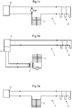
- a heating device comprises an energy well 2, for example a geothermal source in the form of a heating hole, i.e., a bore hole.
- the energy well can be a solar energy device, such as solar panels.
- stored energy can also be used.
- a heat pump 3 is adapted to take up and transfer heat from the energy well 2 by the aid of a line from the energy well to the heat pump 3 for transport of a liquid, preferably anti-freeze liquid, preferably a so called brine solution.
- the heat pump is preferably a property heat pump located in a residence building.
- a heat extraction device 4 is connected to the heat pump 3 which is adapted to selectively be brought into a connected and a disconnected position by means of valves (not shown).
- Thaw coils 5 are provided for thawing ground surrounding the thaw coils 5 in which the anti-freeze liquid is transportable. The thaw coils 5 are adapted to be selectively connected and disconnected to the line from the energy well to the heat pump 3.
- a heat exchanger 7 is connected to the heat extraction device 4 and is adapted to selectively transfer heat to the thaw coils 5 by the aid of the heat extraction device 4, which preferably is a high power extraction device.
- insulation material is preferably arranged under the thaw coils.
- the thaw coils can be divided into two or more circuits, which preferably are adapted to be separately switched in or out. This can for example be used for selectively thaw some of the surface area under with the thaw coils are provided, in order to save energy and to give priority to some parts.
- heated liquid in a thaw coil circuit warmed by sunshine, for example, can be used for heating other parts of the system.
- a circulation pump P is provided in parallel to the thaw coils 5 to force liquid to circulate there though.
- This circulation pump P is provided with a non-return valve for certain operation modes.
- a control system (not shown in the figures) is adapted for controlling the heating device 1, whereby low temperature heat from the energy well 2 alternatively high temperature heat from the heat pump 3 and the heat extraction device 4 selectively can be used for pre-heating, thawing, or maintenance heating ground surrounding the thaw coils 5.
- the control of the heating device can be done manually, automatically, or based on weather data, wherein weather data comprises actual weather and/or weather forecast.
- Sensors measuring parameters in the system, such as temperature and flow can be used for optimizing the energy use during thawing by controlling the directions of pumps and flow so that heat energy, for example from heated sections of the thaw coils, is used for heating other thaw coil sections or used for recharging the energy well.
- the control system is connected to a first valve A, a second valve B, and a third valve C.
- the first and second valves A, B are arranged to, by means of opening and closing f the same, enable connecting and disconnecting of the thaw coils 5 to the line from the energy well 2 to the heat pump 3, for using low temperature heat from the energy well 2 and high temperature heat from the heat pump 3 and the heat extraction device 4 respectively.
- the third valve C is arranged for diverting of the flow through the line from the energy well 2 to the heat pump 3 via the thaw coils 5.
- first and second valves A, B connect the thaw coils 5 to one of the lines interconnecting the heat pump 3 and the energy well 2 while the third valve C is provided in this line, between the connection points of the first and second valves A, B.
- a bypass line BP with a circulation pump is preferably arranged to form its own circuit together with the thaw coils 5 and the line from the energy well 2 to the heat pump 3. This circuit completely or partly circumvents the heat pump 3, wherein the flow can be varied in the circuit by the aid of the bypass line BP. To this end, the bypass line BP is provide across the two lines interconnecting the heat pump 3 and the energy well 2, between the heat pump 3 and the third valve C.
- the heat pump 3 e.g. the geothermal heat pump, operates.
- the heat pump 3 e.g. the geothermal heat pump, operates or the circulation pump in the heat pump 3 is mechanically operated, i.e. forced controlled during non-operation by the heat pump but when its circulation pump has to operate to provide circulation through the thaw coils.
- the energy well 2 and the thaw coils 5 are connected in series.
- the heat pump 3 is arranged such that the circulation cannot be provided when it is turned OFF.
- the bypass circuit BP having its own circulation pump is provided in this case.
- the energy well 2 and the thaw coils 5 are connected in series. However, the liquid is forced by means of the circulation pump in the bypass circuit BP and the heat pump is disconnected in some way (not shown).
- the heat pump 3 e.g. the geothermal heat pump, operates.
- the thaw coils 5 are disconnected from the energy well 2 by means of the valves A-C and the energy extraction device 4 provides the heat to the thaw coils 5 via the heat exchanger 7.
- the heat pump 3 e.g. the geothermal heat pump, operates.
- This operation mode is similar to the second operation mode but with reversed direction of flow for the liquid. This can be achieved by means of switching valves (not shown) provided outside or in the heat pump 3.
- heat from the thaw coils 5 can be used for recharging the energy well 2, for example during summer, when sunshine heats the thaw coils 5.
- FIG. 2 A second embodiment of a heating device according to the invention and associated operation modes will now be described with reference to Fig. 2 and Figs. 2a-d .
- This second embodiment is similar to the first embodiment and like parts are given the same references.
- this second embodiment exhibits controllers or control units, R1 and R2, provided in the lines interconnecting the energy well 2 and the heat pump 3 and the thaw coils, respectively.
- control units can e.g. comprise fixedly tuned valves or be controlled valves or circulation pumps.
- bypass circuit BP (not shown in Fig. 2 ) can be a part of this control system.
- the heat pump 3 e.g. the geothermal heat pump, can operate, see Fig. 2a .
- This first operation mode is essentially identical to the first operation mode of the first embodiment described above with reference to Fig. 1a .
- the heat pump 3 e.g. the geothermal heat pump
- the circulation pump in the heat pump 3 is mechanically operated, i.e. forced controlled during non-operation by the heat pump but when its circulation pump has to operate to provide circulation through the thaw coils.
- the energy well 2 and the thaw coils 5 are connected in parallel.
- the distribution of fluid between the energy well 2 and the thaw coils 5 are controlled by means of the controllers R1 and R2.
- the heat pump 3 is arranged such that the circulation cannot be provided when it is turned OFF.
- the bypass circuit BP having its own circulation pump is provided in this case.
- the energy well 2 and the thaw coils 5 are connected in parallel.
- the liquid is forced by means of the circulation pump in the bypass circuit BP and the heat pump is disconnected in some way (not shown).
- the heat pump 3 e.g. the geothermal heat pump, operates.
- the thaw coils 5 are disconnected from the energy well 2 by means of the valves V1 and V2 and the energy extraction device 4 provides the heat to the thaw coils 5 via the heat exchanger 7.
- the first and second embodiments are different from each other in their operation modes with thawing solely using brine solution in that in the first embodiment the thaw coils are connected in series, i.e. connected in a serial connection way, to the energy wells and in the second embodiment they are connected in parallel, i.e. connected in a parallel connection way.
- An advantage of the first embodiment is a simpler system than the second embodiment. There is no need for controlling/distribution between parallel circuits.
- An advantage of the second embodiment is the possibility to adjust the flow between the parallel circuits which enables a better optimization in different situations. For instance, a forced flow through the thaw coils 5 provides a more uniform heat transfer to different parts in the thawing system.
- FIG. 3 A third embodiment of a heating device according to the invention and associated operation modes will now be described with reference to Fig. 3 and Figs. 3a-d .
- This third embodiment is similar to the first and second embodiments and like parts are given the same references.
- this third embodiment exhibits a separate pump P for driving fluid through the energy well 2.
- the energy well 2 and the thaw coils 5 are connected to the heat pump 3 in such way that fluid can be brought to flow in a circuit comprising the energy well 2 and the thaw coils 5 without passing the heat pump 3.
- the heat pump 3 e.g. the geothermal heat pump, can operate, see Fig. 3a .
- This first operation mode is essentially identical to the first operation mode of the first embodiment described above with reference to Fig. 1a .
- the heat pump 3 e.g. the geothermal heat pump, operates or the circulation pump in the heat pump 3 is mechanically operated, i.e. forced controlled during non-operation by the heat pump but when its circulation pump has to operate to provide circulation through the thaw coils.
- the energy well 2 and the thaw coils 5 are interconnected.
- the heat pump 3 is arranged such that circulation thorough the energy well 2 is achieved for heating the building. Also, the energy well 2 provides energy for heating the thaw coils 5 by circulating fluid by means of the pump P through the circuit formed by the energy well 2 and the thaw coils 5..
- the heat pump 3 e.g. the geothermal heat pump, operates.
- the energy extraction device 4 provides the heat to the thaw coils 5 via the heat exchanger 7.
Landscapes
- Engineering & Computer Science (AREA)
- General Engineering & Computer Science (AREA)
- Mechanical Engineering (AREA)
- Architecture (AREA)
- Civil Engineering (AREA)
- Structural Engineering (AREA)
- Thermal Sciences (AREA)
- Physics & Mathematics (AREA)
- Chemical & Material Sciences (AREA)
- Combustion & Propulsion (AREA)
- Life Sciences & Earth Sciences (AREA)
- Sustainable Development (AREA)
- Sustainable Energy (AREA)
- Steam Or Hot-Water Central Heating Systems (AREA)
- Road Paving Structures (AREA)
Claims (15)
- Heizvorrichtung (1), umfassend:eine Energiequelle (2),eine Wärmepumpe (3), die angepasst ist, Wärme von der Energiequelle (2) aufzunehmen und mit Hilfe einer Leitung von der Energiequelle zur Wärmepumpe (3) zum Transport von Gefrierschutzflüssigkeit zu übertragen,dadurch gekennzeichnet, dass die Heizvorrichtung (1) weiter umfasst:eine Wärmeextraktionsvorrichtung (4), die mit der Wärmepumpe (3) verbunden ist, die selektiv in eine verbundene und getrennte Position gebracht werden kann,Abtauspulen (5) zum Abtauen von Boden, der die Abtauspulen (5) umgibt, in denen die Gefrierschutzflüssigkeit transportiert werden kann, welche Abtauspulen (5) selektiv mit der Leitung von der Energiequelle zur Wärmepumpe (3) verbunden und von dieser getrennt werden können,einen Wärmetauscher (7), der mit der Wärmeextraktionsvorrichtung (4) verbunden ist, angepasst, mit Hilfe der Wärmeextraktionsvorrichtung (4) selektiv Wärme zu den Abtauspulen (5) zu übertragen,ein Steuersystem, das angepasst ist, die Heizvorrichtung (1) zu steuern, wodurch Wärme niedriger Temperatur von der Energiequelle (2), alternativ Wärme hoher Temperatur von der Wärmepumpe (3) und der Wärmeextraktionsvorrichtung (4), selektiv zum Vorheizen, Abtauen oder Beibehalten von Aufheizen von Boden, der die Abtauspulen (5) umgibt, verwendet werden kann.
- Heizvorrichtung (1) nach Anspruch 1, wobei die Energiequelle (2) eines der folgenden ist: mindestens eine geothermale Wärmebohrung und ein Solarpanel.
- Heizvorrichtung (1) nach einem der vorstehenden Ansprüche, wobei die Wärmeextraktionsvorrichtung (4) eine Hochleistungsextraktionsvorrichtung ist.
- Heizvorrichtung (1) nach einem der vorstehenden Ansprüche, wobei die Gefrierschutzflüssigkeit eine Salzwasserlösung ist.
- Heizvorrichtung (1) nach einem der vorstehenden Ansprüche, wobei die Wärmepumpe eine Grundstückswärmepumpe ist.
- Heizvorrichtung (1) nach einem der vorstehenden Ansprüche, wobei die Steuerung der Heizvorrichtung (1) manuell, automatisch oder basierend auf Wetterdaten vorgenommen wird, wobei Wetterdaten aktuelles Wetter und/oder Wettervorhersage umfasst.
- Heizvorrichtung (1) nach einem der vorstehenden Ansprüche, wobei Isoliermaterial unter den Abtauspulen (5) angeordnet ist.
- Heizvorrichtung (1) nach einem der vorstehenden Ansprüche, wobei ein erstes Ventil (A) und ein zweites Ventil (B) angeordnet sind, mit Hilfe von Öffnen und Schließen derselben, ein Verbinden und Trennen der Abtauspulen (5) mit der/von der Leitung von der Energiequelle (2) zur Wärmepumpe (3) zu ermöglichen, um Wärme niedriger Temperatur von der Energiequelle (2) beziehungsweise Wärme hoher Temperatur von der Wärmepumpe (3) und der Wärmeextraktionsvorrichtung (4) zu verwenden, wobei ein drittes Ventil (C) angeordnet ist, den Fluss durch die Leitung von der Energiequelle (2) zur Wärmepumpe (3) über die Abtauspulen (5) umzuleiten.
- Heizvorrichtung (1) nach einem der vorstehenden Ansprüche, wobei eine Umgehungsleitung (BP) mit einer Zirkulationspumpe angeordnet ist, gemeinsam mit den Abtauspulen (5) und der Leitung von der Energiequelle (2) zur Wärmepumpe (3) ihren eigenen Kreislauf zu bilden, welcher Kreislauf die Wärmepumpe (3) vollständig oder teilweise umläuft, wobei der Fluss im Kreislauf mit Hilfe der Umgehungsleitung (BP) variiert werden kann.
- Heizvorrichtung (1) nach einem der vorstehenden Ansprüche, wobei die Abtauspulen (5) mit der Leitung von der Energiequelle (2) zur Wärmepumpe (3) auf eine serielle Verbindungsweise oder eine parallele Verbindungsweise verbunden sind.
- Heizvorrichtung (1) nach einem der vorstehenden Ansprüche, wobei die Wärmepumpe (3), die angeordnet ist Wärme von der Energiequelle (2) aufzunehmen und zu übertragen, und die Wärmepumpe (3), mit der die Wärmeextraktionsvorrichtung (4) verbunden ist, ein und dieselbe Wärmepumpe (3) ist.
- Heizvorrichtung (1) nach einem der vorstehenden Ansprüche, die angepasst ist, mit einem anpassbaren Ausgang selektiv Wärme an die Abtauspulen (5) zu übertragen.
- Heizvorrichtung (1) nach einem der vorstehenden Ansprüche, wobei die Abtauspulen (5) in mindestens zwei Kreisläufe geteilt sind, die bevorzugt angepasst sind, getrennt ein- oder ausgeschaltet zu werden.
- Verfahren zum Abtauen von Boden mit Hilfe einer Heizvorrichtung (1) nach einem der vorstehenden Ansprüche 1-13, das Verfahren dadurch gekennzeichnet, dass es umfasst:- selektives Zuführen von Wärme zu den Abtauspulen (5) von einer Energiequelle (2), mit Hilfe eines Steuersystems der Heizvorrichtung (1), angepasst, die Heizvorrichtung (1) zu steuern, und alternativ- selektives Zuführen von Wärme zu den Abtauspulen (5) von einer Wärmepumpe (3) über eine Wärmeextraktionsvorrichtung (4) und einen Wärmetauscher (7), mit Hilfe des Steuersystems (6).
- Verfahren zum Abtauen von Boden nach Anspruch 14, wobei- Zuführen von Wärme an die Abtauspulen (5) von der Energiequelle (2) dadurch ausgeführt wird, dass ein erstes Ventil (A) und ein zweites Ventil (B) zum Verbinden der Abtauspulen (5) mit der Leitung von der Energiequelle (2) zur Wärmepumpe (3) offengehalten werden, wobei das alternative- Zuführen von Wärme an die Abtauspulen (5) von der Wärmepumpe (3) dadurch ausgeführt wird, dass ein erstes Ventil (A) und ein zweites Ventil (B) geschlossen gehalten werden und ein drittes Ventil (C) zum Umleiten des Flusses durch die Leitung von der Energiequelle (2) zur Wärmepumpe (3) offengehalten wird und die Wärmeextraktionsvorrichtung (4) in einer verbundenen Position ist.
Applications Claiming Priority (2)
| Application Number | Priority Date | Filing Date | Title |
|---|---|---|---|
| SE1450646A SE539071C2 (sv) | 2014-05-28 | 2014-05-28 | Upptiningsanläggning |
| PCT/SE2015/050618 WO2015183174A1 (en) | 2014-05-28 | 2015-05-28 | Heating device |
Publications (3)
| Publication Number | Publication Date |
|---|---|
| EP3149244A1 EP3149244A1 (de) | 2017-04-05 |
| EP3149244A4 EP3149244A4 (de) | 2018-02-14 |
| EP3149244B1 true EP3149244B1 (de) | 2019-04-17 |
Family
ID=54699367
Family Applications (1)
| Application Number | Title | Priority Date | Filing Date |
|---|---|---|---|
| EP15799242.1A Active EP3149244B1 (de) | 2014-05-28 | 2015-05-28 | Heizvorrichtung und verfahren zum entfrosten des bodens |
Country Status (5)
| Country | Link |
|---|---|
| US (1) | US10208433B2 (de) |
| EP (1) | EP3149244B1 (de) |
| CA (1) | CA2985038C (de) |
| SE (1) | SE539071C2 (de) |
| WO (1) | WO2015183174A1 (de) |
Family Cites Families (13)
| Publication number | Priority date | Publication date | Assignee | Title |
|---|---|---|---|---|
| US4344414A (en) * | 1978-04-21 | 1982-08-17 | Balch Joseph C | Solar-earth thermal system |
| US5081848A (en) * | 1990-11-07 | 1992-01-21 | Rawlings John P | Ground source air conditioning system comprising a conduit array for de-icing a nearby surface |
| US5224357A (en) * | 1991-07-05 | 1993-07-06 | United States Power Corporation | Modular tube bundle heat exchanger and geothermal heat pump system |
| US5368092A (en) * | 1993-12-27 | 1994-11-29 | Biotherm Hydronic, Inc. | Apparatus and method for controlling temperature of a turf field |
| US5461876A (en) * | 1994-06-29 | 1995-10-31 | Dressler; William E. | Combined ambient-air and earth exchange heat pump system |
| US20080173260A1 (en) * | 2001-04-12 | 2008-07-24 | Jack Lange | Heat transfer from a source to a fluid to be heated using a heat driven loop |
| JP2003261908A (ja) * | 2002-03-11 | 2003-09-19 | Kubota Corp | 融雪設備 |
| JP2003279193A (ja) * | 2002-03-26 | 2003-10-02 | Kubota Corp | 熱源設備 |
| US20040016740A1 (en) * | 2002-07-24 | 2004-01-29 | Mcdonald Corey E. | Method and device for heating a surface |
| JP4589822B2 (ja) * | 2004-08-19 | 2010-12-01 | 新日本製鐵株式会社 | 道路融雪パネル |
| US9945080B2 (en) * | 2005-02-17 | 2018-04-17 | Greenheat Ip Holdings, Llc | Grounded modular heated cover |
| KR101091210B1 (ko) * | 2009-05-28 | 2011-12-07 | 코오롱건설주식회사 | 아파트 지열냉난방 설비를 이용한 도로 결빙 방지 시스템 |
| SE537437C2 (sv) * | 2010-08-09 | 2015-04-28 | Water Crossing Inc | Anordning för uppvärmning av en markyta medelst en rörcirkulationskrets |
-
2014
- 2014-05-28 SE SE1450646A patent/SE539071C2/sv unknown
-
2015
- 2015-05-28 WO PCT/SE2015/050618 patent/WO2015183174A1/en not_active Ceased
- 2015-05-28 EP EP15799242.1A patent/EP3149244B1/de active Active
- 2015-05-28 CA CA2985038A patent/CA2985038C/en active Active
-
2016
- 2016-11-28 US US15/361,506 patent/US10208433B2/en active Active
Non-Patent Citations (1)
| Title |
|---|
| None * |
Also Published As
| Publication number | Publication date |
|---|---|
| EP3149244A4 (de) | 2018-02-14 |
| WO2015183174A1 (en) | 2015-12-03 |
| SE1450646A1 (sv) | 2015-11-29 |
| EP3149244A1 (de) | 2017-04-05 |
| CA2985038C (en) | 2022-08-30 |
| CA2985038A1 (en) | 2015-12-03 |
| SE539071C2 (sv) | 2017-04-04 |
| US20170081806A1 (en) | 2017-03-23 |
| US10208433B2 (en) | 2019-02-19 |
Similar Documents
| Publication | Publication Date | Title |
|---|---|---|
| EP3074699B1 (de) | Vorrichtung und verfahren zum erwärmen von luft bei einer luftbehandlung vorrichtung | |
| JP5415428B2 (ja) | ヒート・ポンプ装置 | |
| US20130160985A1 (en) | Refrigerant charge management in a heat pump water heater | |
| CN108885014A (zh) | 热泵系统和用于监测热泵系统中的阀门泄漏的方法 | |
| JP2019500566A (ja) | ヒートポンピングの方法およびシステム | |
| CN110106863B (zh) | 一种热电制冷人工地层冻结器 | |
| US20100018679A1 (en) | Isothermal method and device using periodic direction-change utility water flow | |
| JP2010175136A (ja) | 地中熱ヒートポンプ装置 | |
| DE10118572B4 (de) | Wärmeversorgungssystem | |
| JP2020509326A (ja) | 地域熱エネルギー分配システムのための局所熱エネルギー消費アセンブリ及び局所熱エネルギー生成アセンブリ | |
| US20200096262A1 (en) | Latent heat accumulator system comprising a latent heat accumulator and method for operating a latent heat accumulator system | |
| KR101631508B1 (ko) | 태양열 및 지열히트펌프를 이용한 노면 온도조절 시스템 | |
| US20200166291A1 (en) | Latent heat storage system having a latent heat storage device and method for operating a latent heat storage system | |
| KR20090099392A (ko) | 다용도 결빙 방지 장치 | |
| EP2453178B1 (de) | Steuervorrichtung für ein Heizsystem und Heizsystem | |
| EP3149244B1 (de) | Heizvorrichtung und verfahren zum entfrosten des bodens | |
| EP2310751B1 (de) | Wärmegradientfluidendkammer für mehrere heiz- und kühlsysteme | |
| KR101721888B1 (ko) | 듀얼 압축기 공기열원 히트펌프에 의한 계절간 지열에너지 열적평형 보상제어시스템의 제상제어시스템 | |
| KR101734996B1 (ko) | 고효율 가스엔진식 히트펌프 시스템 | |
| CN110878956B (zh) | 用于热泵系统的控制方法及热泵系统 | |
| IL278351B1 (en) | Portable system kit for hot water production, heating and/or cooling | |
| JP2012063062A (ja) | 地下蓄熱層を有する冷暖房システム及び同冷暖房システムに用いる地下蓄熱層の構造 | |
| KR20110090176A (ko) | 열교환 시스템 및 이의 제어방법 | |
| CN108709268A (zh) | 一种新型跨季节自然蓄冷空调系统 | |
| JPH04319103A (ja) | 路面温度の調節装置 |
Legal Events
| Date | Code | Title | Description |
|---|---|---|---|
| STAA | Information on the status of an ep patent application or granted ep patent |
Free format text: STATUS: THE INTERNATIONAL PUBLICATION HAS BEEN MADE |
|
| PUAI | Public reference made under article 153(3) epc to a published international application that has entered the european phase |
Free format text: ORIGINAL CODE: 0009012 |
|
| STAA | Information on the status of an ep patent application or granted ep patent |
Free format text: STATUS: REQUEST FOR EXAMINATION WAS MADE |
|
| 17P | Request for examination filed |
Effective date: 20161222 |
|
| AK | Designated contracting states |
Kind code of ref document: A1 Designated state(s): AL AT BE BG CH CY CZ DE DK EE ES FI FR GB GR HR HU IE IS IT LI LT LU LV MC MK MT NL NO PL PT RO RS SE SI SK SM TR |
|
| AX | Request for extension of the european patent |
Extension state: BA ME |
|
| DAV | Request for validation of the european patent (deleted) | ||
| DAX | Request for extension of the european patent (deleted) | ||
| A4 | Supplementary search report drawn up and despatched |
Effective date: 20180116 |
|
| REG | Reference to a national code |
Ref country code: DE Ref legal event code: R079 Ref document number: 602015028569 Country of ref document: DE Free format text: PREVIOUS MAIN CLASS: E01C0011260000 Ipc: E01C0011240000 |
|
| GRAP | Despatch of communication of intention to grant a patent |
Free format text: ORIGINAL CODE: EPIDOSNIGR1 |
|
| STAA | Information on the status of an ep patent application or granted ep patent |
Free format text: STATUS: GRANT OF PATENT IS INTENDED |
|
| RIC1 | Information provided on ipc code assigned before grant |
Ipc: E01H 5/10 20060101ALI20181016BHEP Ipc: E01C 13/08 20060101ALI20181016BHEP Ipc: F24D 3/18 20060101ALI20181016BHEP Ipc: F25B 30/06 20060101ALI20181016BHEP Ipc: F25B 25/00 20060101ALI20181016BHEP Ipc: E01C 11/24 20060101AFI20181016BHEP Ipc: E01C 11/26 20060101ALI20181016BHEP |
|
| INTG | Intention to grant announced |
Effective date: 20181114 |
|
| GRAS | Grant fee paid |
Free format text: ORIGINAL CODE: EPIDOSNIGR3 |
|
| GRAA | (expected) grant |
Free format text: ORIGINAL CODE: 0009210 |
|
| STAA | Information on the status of an ep patent application or granted ep patent |
Free format text: STATUS: THE PATENT HAS BEEN GRANTED |
|
| AK | Designated contracting states |
Kind code of ref document: B1 Designated state(s): AL AT BE BG CH CY CZ DE DK EE ES FI FR GB GR HR HU IE IS IT LI LT LU LV MC MK MT NL NO PL PT RO RS SE SI SK SM TR |
|
| REG | Reference to a national code |
Ref country code: GB Ref legal event code: FG4D |
|
| REG | Reference to a national code |
Ref country code: CH Ref legal event code: EP |
|
| REG | Reference to a national code |
Ref country code: DE Ref legal event code: R096 Ref document number: 602015028569 Country of ref document: DE |
|
| REG | Reference to a national code |
Ref country code: AT Ref legal event code: REF Ref document number: 1121692 Country of ref document: AT Kind code of ref document: T Effective date: 20190515 Ref country code: IE Ref legal event code: FG4D |
|
| REG | Reference to a national code |
Ref country code: CH Ref legal event code: NV Representative=s name: VALIPAT S.A. C/O BOVARD SA NEUCHATEL, CH |
|
| REG | Reference to a national code |
Ref country code: NL Ref legal event code: MP Effective date: 20190417 |
|
| REG | Reference to a national code |
Ref country code: LT Ref legal event code: MG4D |
|
| PG25 | Lapsed in a contracting state [announced via postgrant information from national office to epo] |
Ref country code: NL Free format text: LAPSE BECAUSE OF FAILURE TO SUBMIT A TRANSLATION OF THE DESCRIPTION OR TO PAY THE FEE WITHIN THE PRESCRIBED TIME-LIMIT Effective date: 20190417 |
|
| PG25 | Lapsed in a contracting state [announced via postgrant information from national office to epo] |
Ref country code: FI Free format text: LAPSE BECAUSE OF FAILURE TO SUBMIT A TRANSLATION OF THE DESCRIPTION OR TO PAY THE FEE WITHIN THE PRESCRIBED TIME-LIMIT Effective date: 20190417 Ref country code: HR Free format text: LAPSE BECAUSE OF FAILURE TO SUBMIT A TRANSLATION OF THE DESCRIPTION OR TO PAY THE FEE WITHIN THE PRESCRIBED TIME-LIMIT Effective date: 20190417 Ref country code: AL Free format text: LAPSE BECAUSE OF FAILURE TO SUBMIT A TRANSLATION OF THE DESCRIPTION OR TO PAY THE FEE WITHIN THE PRESCRIBED TIME-LIMIT Effective date: 20190417 Ref country code: SE Free format text: LAPSE BECAUSE OF FAILURE TO SUBMIT A TRANSLATION OF THE DESCRIPTION OR TO PAY THE FEE WITHIN THE PRESCRIBED TIME-LIMIT Effective date: 20190417 Ref country code: NO Free format text: LAPSE BECAUSE OF FAILURE TO SUBMIT A TRANSLATION OF THE DESCRIPTION OR TO PAY THE FEE WITHIN THE PRESCRIBED TIME-LIMIT Effective date: 20190717 Ref country code: PT Free format text: LAPSE BECAUSE OF FAILURE TO SUBMIT A TRANSLATION OF THE DESCRIPTION OR TO PAY THE FEE WITHIN THE PRESCRIBED TIME-LIMIT Effective date: 20190817 Ref country code: ES Free format text: LAPSE BECAUSE OF FAILURE TO SUBMIT A TRANSLATION OF THE DESCRIPTION OR TO PAY THE FEE WITHIN THE PRESCRIBED TIME-LIMIT Effective date: 20190417 Ref country code: LT Free format text: LAPSE BECAUSE OF FAILURE TO SUBMIT A TRANSLATION OF THE DESCRIPTION OR TO PAY THE FEE WITHIN THE PRESCRIBED TIME-LIMIT Effective date: 20190417 |
|
| PG25 | Lapsed in a contracting state [announced via postgrant information from national office to epo] |
Ref country code: RS Free format text: LAPSE BECAUSE OF FAILURE TO SUBMIT A TRANSLATION OF THE DESCRIPTION OR TO PAY THE FEE WITHIN THE PRESCRIBED TIME-LIMIT Effective date: 20190417 Ref country code: BG Free format text: LAPSE BECAUSE OF FAILURE TO SUBMIT A TRANSLATION OF THE DESCRIPTION OR TO PAY THE FEE WITHIN THE PRESCRIBED TIME-LIMIT Effective date: 20190717 Ref country code: PL Free format text: LAPSE BECAUSE OF FAILURE TO SUBMIT A TRANSLATION OF THE DESCRIPTION OR TO PAY THE FEE WITHIN THE PRESCRIBED TIME-LIMIT Effective date: 20190417 Ref country code: GR Free format text: LAPSE BECAUSE OF FAILURE TO SUBMIT A TRANSLATION OF THE DESCRIPTION OR TO PAY THE FEE WITHIN THE PRESCRIBED TIME-LIMIT Effective date: 20190718 Ref country code: LV Free format text: LAPSE BECAUSE OF FAILURE TO SUBMIT A TRANSLATION OF THE DESCRIPTION OR TO PAY THE FEE WITHIN THE PRESCRIBED TIME-LIMIT Effective date: 20190417 |
|
| REG | Reference to a national code |
Ref country code: AT Ref legal event code: MK05 Ref document number: 1121692 Country of ref document: AT Kind code of ref document: T Effective date: 20190417 |
|
| PG25 | Lapsed in a contracting state [announced via postgrant information from national office to epo] |
Ref country code: IS Free format text: LAPSE BECAUSE OF FAILURE TO SUBMIT A TRANSLATION OF THE DESCRIPTION OR TO PAY THE FEE WITHIN THE PRESCRIBED TIME-LIMIT Effective date: 20190817 |
|
| REG | Reference to a national code |
Ref country code: DE Ref legal event code: R097 Ref document number: 602015028569 Country of ref document: DE |
|
| PG25 | Lapsed in a contracting state [announced via postgrant information from national office to epo] |
Ref country code: RO Free format text: LAPSE BECAUSE OF FAILURE TO SUBMIT A TRANSLATION OF THE DESCRIPTION OR TO PAY THE FEE WITHIN THE PRESCRIBED TIME-LIMIT Effective date: 20190417 Ref country code: SK Free format text: LAPSE BECAUSE OF FAILURE TO SUBMIT A TRANSLATION OF THE DESCRIPTION OR TO PAY THE FEE WITHIN THE PRESCRIBED TIME-LIMIT Effective date: 20190417 Ref country code: DK Free format text: LAPSE BECAUSE OF FAILURE TO SUBMIT A TRANSLATION OF THE DESCRIPTION OR TO PAY THE FEE WITHIN THE PRESCRIBED TIME-LIMIT Effective date: 20190417 Ref country code: MC Free format text: LAPSE BECAUSE OF FAILURE TO SUBMIT A TRANSLATION OF THE DESCRIPTION OR TO PAY THE FEE WITHIN THE PRESCRIBED TIME-LIMIT Effective date: 20190417 Ref country code: EE Free format text: LAPSE BECAUSE OF FAILURE TO SUBMIT A TRANSLATION OF THE DESCRIPTION OR TO PAY THE FEE WITHIN THE PRESCRIBED TIME-LIMIT Effective date: 20190417 Ref country code: AT Free format text: LAPSE BECAUSE OF FAILURE TO SUBMIT A TRANSLATION OF THE DESCRIPTION OR TO PAY THE FEE WITHIN THE PRESCRIBED TIME-LIMIT Effective date: 20190417 Ref country code: CZ Free format text: LAPSE BECAUSE OF FAILURE TO SUBMIT A TRANSLATION OF THE DESCRIPTION OR TO PAY THE FEE WITHIN THE PRESCRIBED TIME-LIMIT Effective date: 20190417 |
|
| REG | Reference to a national code |
Ref country code: BE Ref legal event code: MM Effective date: 20190531 |
|
| PLBE | No opposition filed within time limit |
Free format text: ORIGINAL CODE: 0009261 |
|
| STAA | Information on the status of an ep patent application or granted ep patent |
Free format text: STATUS: NO OPPOSITION FILED WITHIN TIME LIMIT |
|
| PG25 | Lapsed in a contracting state [announced via postgrant information from national office to epo] |
Ref country code: IT Free format text: LAPSE BECAUSE OF FAILURE TO SUBMIT A TRANSLATION OF THE DESCRIPTION OR TO PAY THE FEE WITHIN THE PRESCRIBED TIME-LIMIT Effective date: 20190417 Ref country code: LU Free format text: LAPSE BECAUSE OF NON-PAYMENT OF DUE FEES Effective date: 20190528 Ref country code: SM Free format text: LAPSE BECAUSE OF FAILURE TO SUBMIT A TRANSLATION OF THE DESCRIPTION OR TO PAY THE FEE WITHIN THE PRESCRIBED TIME-LIMIT Effective date: 20190417 |
|
| 26N | No opposition filed |
Effective date: 20200120 |
|
| PG25 | Lapsed in a contracting state [announced via postgrant information from national office to epo] |
Ref country code: TR Free format text: LAPSE BECAUSE OF FAILURE TO SUBMIT A TRANSLATION OF THE DESCRIPTION OR TO PAY THE FEE WITHIN THE PRESCRIBED TIME-LIMIT Effective date: 20190417 |
|
| PG25 | Lapsed in a contracting state [announced via postgrant information from national office to epo] |
Ref country code: IE Free format text: LAPSE BECAUSE OF NON-PAYMENT OF DUE FEES Effective date: 20190528 |
|
| PG25 | Lapsed in a contracting state [announced via postgrant information from national office to epo] |
Ref country code: SI Free format text: LAPSE BECAUSE OF FAILURE TO SUBMIT A TRANSLATION OF THE DESCRIPTION OR TO PAY THE FEE WITHIN THE PRESCRIBED TIME-LIMIT Effective date: 20190417 Ref country code: BE Free format text: LAPSE BECAUSE OF NON-PAYMENT OF DUE FEES Effective date: 20190531 |
|
| PG25 | Lapsed in a contracting state [announced via postgrant information from national office to epo] |
Ref country code: CY Free format text: LAPSE BECAUSE OF FAILURE TO SUBMIT A TRANSLATION OF THE DESCRIPTION OR TO PAY THE FEE WITHIN THE PRESCRIBED TIME-LIMIT Effective date: 20190417 |
|
| PG25 | Lapsed in a contracting state [announced via postgrant information from national office to epo] |
Ref country code: HU Free format text: LAPSE BECAUSE OF FAILURE TO SUBMIT A TRANSLATION OF THE DESCRIPTION OR TO PAY THE FEE WITHIN THE PRESCRIBED TIME-LIMIT; INVALID AB INITIO Effective date: 20150528 Ref country code: MT Free format text: LAPSE BECAUSE OF FAILURE TO SUBMIT A TRANSLATION OF THE DESCRIPTION OR TO PAY THE FEE WITHIN THE PRESCRIBED TIME-LIMIT Effective date: 20190417 |
|
| PG25 | Lapsed in a contracting state [announced via postgrant information from national office to epo] |
Ref country code: MK Free format text: LAPSE BECAUSE OF FAILURE TO SUBMIT A TRANSLATION OF THE DESCRIPTION OR TO PAY THE FEE WITHIN THE PRESCRIBED TIME-LIMIT Effective date: 20190417 |
|
| PGFP | Annual fee paid to national office [announced via postgrant information from national office to epo] |
Ref country code: DE Payment date: 20250520 Year of fee payment: 11 |
|
| PGFP | Annual fee paid to national office [announced via postgrant information from national office to epo] |
Ref country code: GB Payment date: 20250519 Year of fee payment: 11 |
|
| PGFP | Annual fee paid to national office [announced via postgrant information from national office to epo] |
Ref country code: FR Payment date: 20250516 Year of fee payment: 11 |
|
| PGFP | Annual fee paid to national office [announced via postgrant information from national office to epo] |
Ref country code: CH Payment date: 20250601 Year of fee payment: 11 |