EP3149294B1 - Ventilanordnung - Google Patents
Ventilanordnung Download PDFInfo
- Publication number
- EP3149294B1 EP3149294B1 EP14755586.6A EP14755586A EP3149294B1 EP 3149294 B1 EP3149294 B1 EP 3149294B1 EP 14755586 A EP14755586 A EP 14755586A EP 3149294 B1 EP3149294 B1 EP 3149294B1
- Authority
- EP
- European Patent Office
- Prior art keywords
- valve
- cylinder
- intake
- arrangement
- side port
- Prior art date
- Legal status (The legal status is an assumption and is not a legal conclusion. Google has not performed a legal analysis and makes no representation as to the accuracy of the status listed.)
- Active
Links
Images


Classifications
-
- F—MECHANICAL ENGINEERING; LIGHTING; HEATING; WEAPONS; BLASTING
- F01—MACHINES OR ENGINES IN GENERAL; ENGINE PLANTS IN GENERAL; STEAM ENGINES
- F01L—CYCLICALLY OPERATING VALVES FOR MACHINES OR ENGINES
- F01L3/00—Lift-valve, i.e. cut-off apparatus with closure members having at least a component of their opening and closing motion perpendicular to the closing faces; Parts or accessories thereof
- F01L3/20—Shapes or constructions of valve members, not provided for in preceding subgroups of this group
- F01L3/205—Reed valves
-
- F—MECHANICAL ENGINEERING; LIGHTING; HEATING; WEAPONS; BLASTING
- F01—MACHINES OR ENGINES IN GENERAL; ENGINE PLANTS IN GENERAL; STEAM ENGINES
- F01L—CYCLICALLY OPERATING VALVES FOR MACHINES OR ENGINES
- F01L1/00—Valve-gear or valve arrangements, e.g. lift-valve gear
- F01L1/46—Component parts, details, or accessories, not provided for in preceding subgroups
- F01L1/462—Valve return spring arrangements
- F01L1/465—Pneumatic arrangements
-
- F—MECHANICAL ENGINEERING; LIGHTING; HEATING; WEAPONS; BLASTING
- F01—MACHINES OR ENGINES IN GENERAL; ENGINE PLANTS IN GENERAL; STEAM ENGINES
- F01L—CYCLICALLY OPERATING VALVES FOR MACHINES OR ENGINES
- F01L3/00—Lift-valve, i.e. cut-off apparatus with closure members having at least a component of their opening and closing motion perpendicular to the closing faces; Parts or accessories thereof
- F01L3/20—Shapes or constructions of valve members, not provided for in preceding subgroups of this group
-
- F—MECHANICAL ENGINEERING; LIGHTING; HEATING; WEAPONS; BLASTING
- F01—MACHINES OR ENGINES IN GENERAL; ENGINE PLANTS IN GENERAL; STEAM ENGINES
- F01L—CYCLICALLY OPERATING VALVES FOR MACHINES OR ENGINES
- F01L2820/00—Details on specific features characterising valve gear arrangements
- F01L2820/03—Auxiliary actuators
- F01L2820/031—Electromagnets
-
- F—MECHANICAL ENGINEERING; LIGHTING; HEATING; WEAPONS; BLASTING
- F01—MACHINES OR ENGINES IN GENERAL; ENGINE PLANTS IN GENERAL; STEAM ENGINES
- F01L—CYCLICALLY OPERATING VALVES FOR MACHINES OR ENGINES
- F01L2820/00—Details on specific features characterising valve gear arrangements
- F01L2820/03—Auxiliary actuators
- F01L2820/034—Pneumatic engines
-
- F—MECHANICAL ENGINEERING; LIGHTING; HEATING; WEAPONS; BLASTING
- F01—MACHINES OR ENGINES IN GENERAL; ENGINE PLANTS IN GENERAL; STEAM ENGINES
- F01L—CYCLICALLY OPERATING VALVES FOR MACHINES OR ENGINES
- F01L3/00—Lift-valve, i.e. cut-off apparatus with closure members having at least a component of their opening and closing motion perpendicular to the closing faces; Parts or accessories thereof
- F01L3/10—Connecting springs to valve members
-
- F—MECHANICAL ENGINEERING; LIGHTING; HEATING; WEAPONS; BLASTING
- F01—MACHINES OR ENGINES IN GENERAL; ENGINE PLANTS IN GENERAL; STEAM ENGINES
- F01L—CYCLICALLY OPERATING VALVES FOR MACHINES OR ENGINES
- F01L5/00—Slide valve-gear or valve-arrangements
- F01L5/14—Slide valve-gear or valve-arrangements characterised by the provision of valves with reciprocating and other movements
- F01L5/18—Slide valve-gear or valve-arrangements characterised by the provision of valves with reciprocating and other movements with reciprocatory valve and other slide valve
-
- F—MECHANICAL ENGINEERING; LIGHTING; HEATING; WEAPONS; BLASTING
- F01—MACHINES OR ENGINES IN GENERAL; ENGINE PLANTS IN GENERAL; STEAM ENGINES
- F01L—CYCLICALLY OPERATING VALVES FOR MACHINES OR ENGINES
- F01L5/00—Slide valve-gear or valve-arrangements
- F01L5/20—Slide valve-gear or valve-arrangements specially for two-stroke engines
-
- F—MECHANICAL ENGINEERING; LIGHTING; HEATING; WEAPONS; BLASTING
- F01—MACHINES OR ENGINES IN GENERAL; ENGINE PLANTS IN GENERAL; STEAM ENGINES
- F01L—CYCLICALLY OPERATING VALVES FOR MACHINES OR ENGINES
- F01L7/00—Rotary or oscillatory slide valve-gear or valve arrangements
- F01L7/06—Rotary or oscillatory slide valve-gear or valve arrangements with disc type valves
-
- F—MECHANICAL ENGINEERING; LIGHTING; HEATING; WEAPONS; BLASTING
- F01—MACHINES OR ENGINES IN GENERAL; ENGINE PLANTS IN GENERAL; STEAM ENGINES
- F01L—CYCLICALLY OPERATING VALVES FOR MACHINES OR ENGINES
- F01L9/00—Valve-gear or valve arrangements actuated non-mechanically
- F01L9/10—Valve-gear or valve arrangements actuated non-mechanically by fluid means, e.g. hydraulic
- F01L9/16—Pneumatic means
-
- F—MECHANICAL ENGINEERING; LIGHTING; HEATING; WEAPONS; BLASTING
- F01—MACHINES OR ENGINES IN GENERAL; ENGINE PLANTS IN GENERAL; STEAM ENGINES
- F01L—CYCLICALLY OPERATING VALVES FOR MACHINES OR ENGINES
- F01L9/00—Valve-gear or valve arrangements actuated non-mechanically
- F01L9/20—Valve-gear or valve arrangements actuated non-mechanically by electric means
Definitions
- the present invention relates to a valve arrangement for a cylinder of an internal combustion engine arrangement.
- the invention is applicable for vehicles, in particularly heavy vehicles, such as e.g. trucks.
- the valve arrangement is of course also applicable for other type of vehicles, such as cars, industrial construction machines, wheel loaders, etc.
- a problem with a two-stage engine is that they are too over-expanded at low loads, which means that there is too much intercooled air, or other type of gas, added to the combustion cylinder, which results in that the over-expansion reaches sub atmospheric pressure.
- the efficiency of the cylinder arrangement is reduced since sub atmospheric pressure will create energy losses.
- EP 1 522 690 relates to a method of operating an internal combustion engine.
- an auxiliary valve is arranged to automatically prevent charge-air back flow from the cylinder.
- US 2007/0204814 describes a split-cycle engine with disc valve assembly having a disc valve inlet which is an annular ring disposed between the engine block and the cylinder head.
- the object is at least partly achieved by a valve arrangement according to claim 1.
- a valve arrangement for a cylinder of an internal combustion engine arrangement comprising a check valve configured to be positioned at an intake side port of the cylinder for controlling gas flow into the cylinder, wherein the valve arrangement further comprises an intake valve means positioned upstream from the check valve, and an actuating means configured to controllably position the intake valve means for closing the intake side port.
- check valve should in the following and throughout the entire description be interpreted as a valve which allows gas or fluid to pass through it in one direction only and thus preventing gas/liquid to flow through it in the other direction. Accordingly, for the above check valve which is configured to be positioned at an intake side port of a cylinder, gas can only flow into the cylinder via the check valve, and not out from the intake side port.
- check valves such as a ball check valve, a diaphragm check valve, or a reed valve which will be described further below.
- intake valve means should in the following and throughout the entire description be interpreted as a further valve configured to be positioned at the intake side port of the cylinder.
- intake valve means should in the following and throughout the entire description be interpreted as a further valve configured to be positioned at the intake side port of the cylinder.
- Various types of valves are of course conceivable, and will be described in further detail below.
- the "actuating means" should be understood as an arrangement which is configured to position the intake valve means in a closed position.
- the actuating means is configured to position the intake valve means in a position such that the intake side port is closed and thus preventing gas from entering the cylinder.
- the actuating means may only need to controllably position the intake valve means in a closed position.
- the actuating means may no longer need to further provide actuation since the intake valve means will be held in position by the difference in pressure between the cylinder pressure and the ambient pressure, which will be described further below. Accordingly, the actuating means may thus only need to provide a relatively short actuating pulse to arrange the intake valve means in position.
- the present invention is based on the insight that by combining a check valve and an intake valve means, a simple valve arrangement is provided which is controlled such that only a desired amount of gas is provided into the cylinder of which the valve arrangement is provided to.
- the intake valve means can be controlled for closing the intake side valve at a desired point in time.
- an advantage of the present invention is that the amount of gas provided into the cylinder, especially at low loads, can be controlled such that too much over-expansion is avoided. Hence, energy losses are reduced and the power efficiency of the cylinder which the valve arrangement is provided to is increased.
- a variable Miller stroke of the cylinder is provided.
- another problem which is mitigated with the present invention is that excessive expansion is reduced. An excessive expansion cools the exhaust temperature which may create a problem for vehicle after treatment systems.
- check valve provides for a "fail safe mode" when starting the engine at situations where otherwise an actuating means may fail to function.
- the check valve increases the reliability for start-up of the engine.
- the check valve may be a reed valve.
- a reed valve should be understood as a specific type of check valve.
- the reed valve has at least one plate, or blade, which provides the valve in an open state when the plate/blade is exposed to pressure from a first side and in a closed state when the plate/blade is exposed to pressure from its other side. More specifically, the reed valve is normally, when not exposed to any pressure, in a closed state.
- the plate/blade of the reed valve is arranged to provide the reed valve in an open state when gas is provided into the cylinder and closed when gas is provided out from the cylinder.
- An advantage of using a reed valve is that the reed valve can be positioned in an open state by means of a relatively low backpressure from the cylinder. This is advantageous since the backpressure in the cylinder generally generates pumping losses, i.e. energy losses. Accordingly, using a reed valve will thus further increase the energy efficiency of the cylinder arrangement. Furthermore, a reed valve is compact in its configuration which is an important aspect of cylinders since it can further reduce dead volumes in the cylinder. Another advantage is that a reed valve has a relatively low force of inertia which makes the opening/closing of the valve a fast process. Hence, the reed valve can quickly turn from an open state to a closed state, and vice versa.
- the valve arrangement may further comprise retracting means configured to position the intake valve means for opening the intake side port when a pressure in the cylinder is above a predetermined pressure threshold limit.
- the intake valve means When the intake valve means has been positioned such that it closes the intake side port of the cylinder and the piston in the cylinder moves downward, the pressure in the cylinder will be reduced and the intake valve means will be kept in the closed position by means of the pressure difference between the pressure inside the cylinder and the pressure outside the cylinder.
- the actuating means may be turned off since the difference in pressure will keep the intake valve means in the closed position.
- the retracting means will position the intake valve means for opening the intake side port.
- the increase in pressure will provide the check valve in the closed state, either before the intake valve is positioned in the open state or at the same time as the intake valve means is positioned in the open state. Accordingly, the intake valve means is automatically positioned in the open position when the pressure in the cylinder reaches the predetermined threshold limit.
- the timing of when the intake valve means is positioned in the open state can be controlled by means of controlling the retracting means.
- the retracting means is a spring, as will be described below, the timing can be controlled by means of the spring stiffness.
- the intake valve means can be arranged to be positioned in the open state before the pressure in the cylinder reaches the atmospheric pressure.
- the intake valve means may be a slide valve, wherein the actuating means is configured to slidingly position the slide valve for closing the intake side port.
- a slide valve is advantageous since it provides for a compact valve arrangement.
- the intake valve means may be a valve plate, wherein the actuating means is configured to tiltably position the valve plate for closing the intake side port.
- the retracting means may be a spring.
- a spring is easily provided and may be arranged in many different forms. Also, a spring with suitable spring stiffness can be chosen such that the intake valve means is positioned in the open position when desired.
- the retracting means may be a torsion spring.
- a torsion spring is particularly useful when having an intake valve means in the form of a valve plate which is configured to tiltably position the valve plate for closing the intake port.
- the torsion spring will be an almost integrated part in the valve plate, thus reducing of the overall size of the valve arrangement.
- the torsion spring can also be adapted to tilt the valve plate to desired amounts.
- the torsion spring can be chosen such that the valve plate is arranged in the open position by rotating the valve plate around the torsion spring by 90 degrees or 180 degrees as seen from the closed state. It can of course be opened to a lesser degree or to a larger degree as well if desired.
- the retracting means may be a coil spring.
- the retracting means may also be a pneumatic spring.
- the actuating means may be a pneumatic actuating means.
- a pneumatic actuating means is advantageous since it can provide a short pulse of pressurized gas that will force the intake valve means to be positioned such that the intake port is closed.
- the intake valve means may be a poppet valve actuated by means of the pneumatic actuating means.
- a poppet valve is advantageous to use when the actuating means is a pneumatic actuating means.
- the actuating means may be an electromagnetic actuating means.
- the electromagnetic actuating means may be a rotating electric motor or a linear electric motor, etc.
- actuating means than those of the above description are of course also conceivable, such as e.g. a permanent magnet, etc.
- the cylinder may comprise a cylinder relief through hole, which in conjunction with a recess arranged in the intake valve means provides fluid communication between an inside volume of the cylinder and a volume delimited by the intake valve means and the check valve when the intake valve means and the check valve are arranged for closing the intake side port.
- the check valve may comprise a check valve relief through hole for providing fluid communication between an inside volume of the cylinder and a volume delimited by the intake valve means and the check valve when the intake valve means and the check valve are arranged for closing the intake side port.
- a further example of relief through hole is provided which allows gas from the cylinder to enter the volume delimited by the intake valve means and the check valve when the intake valve means and the check valve are arranged for closing the intake side port at all times when the check valve is in a closed state.
- a cylinder for an internal combustion engine arrangement comprising a check valve arranged at an intake side port of the cylinder for controlling gas flow into the cylinder, wherein the cylinder further comprises an intake valve means positioned upstream from the check valve, and an actuating means configured to controllably position the intake valve means for closing the intake side port.
- the cylinder may further comprise a second check valve arranged at an outlet side port of the cylinder for controlling gas flow out from the cylinder.
- a check valve is used as an intake valve as well as an outlet valve for the cylinder.
- the advantages of having a check valve at the outlet of the cylinder are analogous to those described above for the check valve at the inlet port.
- the cylinder may be a compression cylinder provided in a split-cycle internal combustion engine.
- an internal combustion engine arrangement comprising a cylinder according to any one of the above described example embodiments.
- a vehicle comprising a cylinder according to any one of the above described example embodiments.
- the vehicle 1 depicted in Fig. 1 is a truck for which the inventive internal combustion engine arrangement 100 and the valve arrangement 101, 201, 301, which will be described in detail below, is particularly suitable for.
- FIG. 2 illustrating an internal combustion engine arrangement 100 provided with a valve arrangement 101, 201, 301 according to example embodiments of the present invention.
- the internal combustion engine arrangement 100 depicted in Fig. 2 is a split-cycle internal combustion engine comprising a compression cylinder 202, two combustion cylinders 204, 206, and an expansion cylinder 208.
- Other configurations of a split-cycle internal combustion engine are of course conceivable, such as e.g. a split-cycle internal combustion engine using two parallel compression cylinders which are each in fluid communication with a respective combustion cylinder.
- two expansion cylinders which are arranged in fluid communication with a respective combustion cylinder, is also conceivable.
- the invention is also applicable for compression cylinders where a cylinder is acting both as a compression cylinder as well as an expansion cylinder.
- a cylinder may provide an expansion stage delimited by the upper end of the piston and the inside of the cylinder and a compression stage delimited by the lower end of the piston and the inside of the cylinder.
- a compression cylinder 202 should in the following and throughout the entire description be interpreted as a cylinder housing a compression piston 302, where the cylinder is arranged to provide compressed intake gas to e.g. a combustion cylinder 204, 206. Accordingly, the compression piston 302 compresses gas inside the compression cylinder, which compressed gas thereafter is transferred to the intake of the combustion cylinders. The pressure level of the compressed gas is then above atmospheric pressure.
- the compression cylinder can work in a two-stroke fashion, which means that when the compression piston is in an upper end position of the cylinder, also known as a top dead centre of the cylinder, gas is provided into the cylinder during the downward motion of the compression piston until the compression piston has reached a desired position, which will be described further below.
- the compression piston When the compression piston thereafter has reached the bottom dead centre of the compression cylinder and is in an upward motion towards the upper end position of the cylinder, the gas provided into the cylinder is compressed due to the volume reduction within the cylinder caused by the reciprocating motion of the compression piston. At a desired point in time, the compressed gas is directed out from the compression cylinder and to the intake of the combustion cylinder.
- the gas which is compressed by the compression cylinder may, for example, be ambient air.
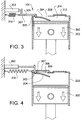
- the valve arrangement 101 comprises a check valve 304, in Fig. 3 depicted as a reed valve, and an intake valve means 306, depicted as a slide valve.
- the valve arrangement 101 i.e. the check valve 304 and the intake valve means 306, is positioned at an intake side port 308 of the compression cylinder 202.
- gas is allowed to enter the compression cylinder 202 via the intake side port 308 when the valve arrangement 101 is arranged in the open position as illustrated in Fig. 3 .
- the valve arrangement 101 comprises an actuating means 303.
- the actuating means 303 is arranged to controllably position the intake valve means 306 in a closed position, such that the intake side port 308 is closed. Controllably positioning the intake valve means 306 for closing the intake side port 308 of the cylinder can be achieved by a short pulse or the like, either hydraulically, pneumatically, or by means of an electric motor, etc.
- the actuating means illustrated in Fig. 3 is an actuator in the form of a reciprocating cylinder.
- the valve arrangement 101 also comprises a retracting means 310, here in the form of a coil spring, which is arranged in an un-tensioned state when the intake valve means 306 is arranged in an open position.
- the retracting means 310 is configured to position the intake valve means in the open position when the spring force exceeds a clamping force exerted on the intake valve means from the pressure of the compression cylinder 202.
- the compression cylinder 202 depicted in Fig. 3 further comprises a second check valve 312 arranged at an outlet side port 314 of the cylinder.
- the second check valve 312 here in the form of a reed valve, is configured to be positioned in an open state when compressed gas is to be forced out from the compression cylinder 202 and into e.g. the combustion cylinders 204, 206 depicted in Fig. 2 .
- FIG. 3 - 6 in order to describe the functionality of the valve arrangement 101 in combination with the compression cylinder 202.
- the description is made for a compression cylinder 202 working in a two-stroke compression cycle.
- the invention is equally applicable for a cylinder working in a four stroke compression cycle as well.
- the compression piston 302 is positioned at an upper end position within the compression cylinder 202.
- the compression piston 302 is in a downward motion towards a lower end position of the compression cylinder, i.e. the bottom dead centre of the compression cylinder 202.
- the intake valve means 306 is arranged in an open position by means of the retracting force from the retracting means 310.
- the check valve 306 is in the open position due to suction forces arising from the pressure difference between the pressure inside the compression cylinder and the pressure outside from the compression cylinder during the downward motion of the compression piston.
- gas is allowed to enter the compression cylinder since both the intake valve means 306 as well as the check valve 304 are arranged in the open position.
- the second check valve 312 is arranged in a closed position.
- the compression piston 302 is still in a downward motion towards the bottom dead centre of the compression cylinder 302.
- the intake valve means 306 is now positioned in a closed state, thus preventing gas from entering the compression cylinder via the intake side port 308.
- the closing of the intake valve means 306 is executed by a short pulse from the actuating means 303.
- the actuating force from the short pulse is exceeding the spring force from the retracting means 310 such that the intake valve means 306 is closing the intake side port 308.
- the compression cylinder 302 continues its downward motion towards the bottom dead centre of the compression cylinder 202, the pressure within the compression cylinder 202 will be lower compared to the pressure outside the cylinder.
- the intake valve means 306 is in this stage not exposed to an actuating force from the actuating means 303.
- the compression cylinder will not receive any further gas during the remaining downward motion of the compression piston 302 within the compression cylinder 202.
- the compression cylinder has controllably received a desired amount of gas.
- a cylinder relief through hole 305 is arranged in the upper portion of the cylinder 202.
- the cylinder relief through hole 305 is aligned with a recess 307 arranged in the intake valve means 306.
- gas can be provided through the cylinder relief through hole 305 and into the intake side port 308 via the recess 307 in the intake valve means 306.
- the compression piston 302 is in an upward motion toward the upper end position of the compression cylinder 202.
- the compression piston 302 is positioned approximately at the same position as depicted in Fig. 4 where the intake valve means 306 was controllably arranged in the closed position.
- the pressure within the compression cylinder 202 will be approximately the same as the pressure outside the compression cylinder 202.
- the retracting force from the retracting means will, shortly before the piston reaches the position in Fig. 5 , or when it has reached the position in Fig.
- the intake valve means 306 exceed the above described clamping force and the intake valve means will, by means of the retracting force, be provided at its open position.
- the check valve 304 will be positioned in its closed position, i.e. the check valve will be arranged in such a way that the intake side port is closed and thus not allowing gas to enter the compression cylinder 302.
- Fig. 5 depicts a small opening of the intake side port, it should be readily understood that when the intake valve means 306 is forced to its open stage, the check valve 304 will be in its closed state such that gas is prevented from being directed out from the compression cylinder via the intake side port 308.
- the compression piston 302 is still in an upward motion towards the upper end position of the compression cylinder 202.
- the intake valve means 306 is arranged in the open position and kept in this position by means of the retracting means 310, while the check valve 304 is arranged in its closed state.
- gas is prevented from being directed out from the compression cylinder 202 via the intake side port 308.
- the second check valve 312 will, at this fourth stage, be arranged in an open position such that compressed gas can be forced out from the compression cylinder 202 via the outlet side port 314 and into e.g. the combustion cylinders 204, 206 as depicted and described in relation to Fig. 2 .
- the flow of gas into the compression cylinder is controlled such that only a desired amount of gas is provided therein.
- the compression cylinder 202 will not receive gas during the complete downward motion of the compression piston 202 within the compression cylinder 302, but instead only receive gas during a specific and desired amount of time of the downward motion of the compression piston 302.
- FIG. 7 and 8 illustrating two further example embodiments of the valve arrangement according to the present invention.
- the functionality of opening and closing the various valves are similar to the above description of the four stages in Figs. 3 - 6 unless indicated otherwise.
- Fig. 7 illustrating a valve arrangement 201 having an intake valve means in the form of a poppet valve 702, and a check valve in the form of a reed valve.
- the check valve 304 of the embodiment depicted in Fig. 7 has the same functionality as described above and will not be described further.
- the poppet valve 702 on the other hand is connected to the retracting means 310 on the upper end thereof, which end is facing away from the intake side port 308 of the compression cylinder 202.
- the retracting means 310 is in the form of a coil spring and has similar functionality as the coil spring described above.
- the poppet valve 702 is configured to be controllably positioned in a closed state where it prevents gas from entering the compression cylinder via the intake side port 308.
- a piston 704 of the poppet valve is configured to close the intake side port 308 of the compression cylinder 202.
- the poppet valve 702 in its closed state i.e. where it is closing the intake side port of the compression cylinder 202, is depicted in Fig. 7 with the piston 704 in dashed lines.
- the retracting means 310 is configured to retract the piston 704 of the poppet valve 702 to an open state, which open state is illustrated with the piston 704 in solid lines.
- actuating means 303 in the form of a pneumatic actuating means 303 positioned at a rear end of the poppet valve in relation to the intake side port 308 and connected to the poppet valve by means of a hose 706 or the like.
- the piston 704 of the poppet valve is arranged between the pneumatic actuating means and the intake side port 308 of the compression cylinder 202.
- the pneumatic actuating means 303 is configured to provide the above described actuating force by means of providing a short pulse of pressurised air, which will force the piston 704 of the poppet valve 702 to be arranged in the closed position until the pressure difference between the pressure inside the compression cylinder 202 and the pressure outside the compression cylinder 202 is such that it will keep the piston 704 in the closed position, as described above.
- FIG. 8 illustrating a still further example embodiment of the valve arrangement 301 according to the present invention.
- the difference between the valve arrangement 301 depicted in Fig. 8 and the valve arrangements depicted in Figs. 3 and 7 is mainly relating to the intake valve means 802 and its associated retracting means 804.
- the valve arrangement 301 depicted in Fig. 8 comprises an intake valve means 802, in the form of a valve plate, and a check valve in the form of a reed valve as described above.
- the intake valve means 802 is connected to a retracting means 804 in the form of a torsion spring.
- the intake valve means 802 is also, as for the embodiment depicted and described in relation to Fig. 3 , connected to an actuating means 303 for controllably position the intake valve means for closing the intake side port 308.
- the valve plate 802 is configured to be tiltably arranged in the open and closed position, respectively.
- valve plate 8 is tilting between the closed position (seen in dashed lines) and the open position (seen in solid lines) by an approximately 90 degrees tilting.
- the valve plate may of course be tilting between an open state and a closed state by e.g. 180 degrees instead of 90 degrees.
- the check valve 304 comprises a check valve relief through hole 705 which allows gas to be guided from the inside of the cylinder 202 and into the volume which is delimited by the intake valve means and the check valve when these valves are arranged in a closed state.
- the intake valve means may also be a slide plate which is connected to a retracting means in the form of a torsion spring such that the slide plate slides between an open position and a closed position by means of rotating the slide plate relative to the compression cylinder.
Landscapes
- Engineering & Computer Science (AREA)
- Mechanical Engineering (AREA)
- General Engineering & Computer Science (AREA)
- Physics & Mathematics (AREA)
- Geometry (AREA)
- Check Valves (AREA)
- Valve Device For Special Equipments (AREA)
Claims (15)
- Ventilanordnung (101, 201, 301) für einen Zylinder (202) einer Brennkraftmaschinenanordnung (100), wobei die Ventilanordnung (101, 201, 301) ein Rückschlagventil (304) umfasst, das konfiguriert ist, um an einem Einlassseitenport (308) des Zylinders (202) zum Steuern des Gasflusses in den Zylinder (202) positioniert zu sein, und
ein Einlassventilmittel (306, 702, 802), das stromaufwärts des Rückschlagventils (304) positioniert ist, und ein Betätigungsmittel (303), das konfiguriert ist, um das Einlassventilmittel (306, 702, 802) steuerbar zum Schließen des Einlassseitenports (308) zu positionieren, dadurch gekennzeichnet, dass das Einlassventilmittel von dem Betätigungsmittel impulsgesteuert ist. - Ventilanordnung (101, 201, 301) nach Anspruch 1, wobei das Rückschlagventil (304) ein Reed-Ventil ist.
- Ventilanordnung (101, 201, 301) nach den Ansprüchen 1 oder 2, die ferner Rückzugmittel (310, 804) umfasst, die konfiguriert sind, um das Einlassventilmittel (306, 702, 802) zum Öffnen des Einlassseitenports (308) zu positionieren, wenn ein Druck in dem Zylinder oberhalb eines vorbestimmten Druckschwellenlimits liegt.
- Ventilanordnung (101) nach einem der vorstehenden Ansprüche, wobei das Einlassventilmittel (306) ein Schieber ist, wobei das Betätigungsmittel (303) konfiguriert ist, um den Schieber zum Schließen des Einlassseitenports (308) gleitend zu positionieren.
- Ventilanordnung (301) nach einem der Ansprüche 1 bis 3, wobei das Einlassventilmittel (802) eine Ventilplatte ist, wobei das Betätigungsmittel (303) konfiguriert ist, um die Ventilplatte (802) kippbar zum Schließen des Einlassseitenports (308) zu positionieren.
- Ventilanordnung (101, 201, 301) nach Anspruch 3, wobei das Rückzugmittel (310, 804) eine Feder ist.
- Ventilanordnung (201) nach einem der Ansprüche 1 bis 3, wobei das Betätigungsmittel (303) ein pneumatisches Betätigungsmittel ist.
- Ventilanordnung (201) nach Anspruch 7, wobei das Einlassventilmittel ein Tellerventil ist, das mittels des pneumatischen Betätigungsmittels (303) betätigt wird.
- Ventilanordnung (101) nach einem der vorstehenden Ansprüche, wobei der Zylinder (202) eine durchgehende Zylinderentlastungsbohrung (305) umfasst, die gemeinsam mit einer Vertiefung (307), die in dem Eingangsventilmittel (306) eingerichtet ist, Fluidkommunikation zwischen einem Innenvolumen des Zylinders (202) und einem Volumen, das von dem Einlassventilmittel (306) und dem Rückschlagventil (304) abgegrenzt wird, wenn das Einlassventilmittel (306) und das Rückschlagventil (304) zum Schließen des Einlassseitenports (308) eingerichtet sind, bereitstellt.
- Ventilanordnung (101, 201, 301) nach einem der Ansprüche 1 bis 8, wobei das Rückschlagventil (304) eine durchgehende Rückschlagventilentlastungsbohrung (705) zum Bereitstellen von Fluidkommunikation zwischen einem Innenvolumen des Zylinders (202) und einem Volumen, das von dem Einlassventilmittel (306) und dem Rückschlagventil (304) abgegrenzt wird, wenn das Einlassventilmittel (306) und das Rückschlagventil (304) zum Schließen des Einlassseitenports (308) eingerichtet sind, bereitzustellen.
- Zylinder (202), der eine Ventilanordnung nach einem der vorstehenden Ansprüche umfasst.
- Zylinder (202) nach Anspruch 11, der ferner ein zweites Rückschlagventil (312) umfasst, das an einem Auslassseitenport (314) des Zylinders zum Steuern von Gasfluss aus dem Zylinder heraus eingerichtet ist.
- Zylinder (202) nach den Ansprüchen 11 oder 12, wobei der Zylinder ein Kompressionszylinder ist, der in einer Split-Cycle-Brennkraftmaschine bereitgestellt ist.
- Brennkraftmaschinenanordnung, die einen Zylinder (202) nach einem der Ansprüche 11 bis 13 umfasst.
- Fahrzeug, das eine Brennkraftmaschinenanordnung (100) umfasst, die einen Zylinder (202) nach einem der Ansprüche 11 bis 13 umfasst.
Applications Claiming Priority (1)
| Application Number | Priority Date | Filing Date | Title |
|---|---|---|---|
| PCT/EP2014/001426 WO2015180742A1 (en) | 2014-05-28 | 2014-05-28 | A valve arrangement |
Publications (2)
| Publication Number | Publication Date |
|---|---|
| EP3149294A1 EP3149294A1 (de) | 2017-04-05 |
| EP3149294B1 true EP3149294B1 (de) | 2019-09-18 |
Family
ID=51399606
Family Applications (1)
| Application Number | Title | Priority Date | Filing Date |
|---|---|---|---|
| EP14755586.6A Active EP3149294B1 (de) | 2014-05-28 | 2014-05-28 | Ventilanordnung |
Country Status (3)
| Country | Link |
|---|---|
| US (1) | US10233794B2 (de) |
| EP (1) | EP3149294B1 (de) |
| WO (1) | WO2015180742A1 (de) |
Family Cites Families (15)
| Publication number | Priority date | Publication date | Assignee | Title |
|---|---|---|---|---|
| US3687118A (en) * | 1969-07-14 | 1972-08-29 | Yamaha Hatsudaki Kk | Crank chamber compression-type two-cycle engine |
| JPS56162222A (en) * | 1980-05-17 | 1981-12-14 | Honda Motor Co Ltd | Internal-combustion engine |
| JPS5713224A (en) * | 1980-06-28 | 1982-01-23 | Yamaha Motor Co Ltd | Intake system of internal combustion engine |
| US4907544A (en) * | 1989-04-06 | 1990-03-13 | Southwest Research Institute | Turbocharged two-stroke internal combustion engine with four-stroke capability |
| US5495830A (en) * | 1995-04-05 | 1996-03-05 | General Motors Corporation | Variable valve timing |
| US8215292B2 (en) * | 1996-07-17 | 2012-07-10 | Bryant Clyde C | Internal combustion engine and working cycle |
| EP1522690A3 (de) * | 1996-10-25 | 2005-06-08 | Clyde C. Bryant | Verbesserte Brennkraftmaschine und Arbeitstakte |
| JP2001200726A (ja) * | 2000-01-18 | 2001-07-27 | Kawasaki Heavy Ind Ltd | エンジンのリードバルブ冷却装置 |
| US6612273B1 (en) * | 2002-01-15 | 2003-09-02 | Paul Schumacher | Dual-piston compression chamber for two-cycle engines |
| US6513464B1 (en) * | 2002-04-03 | 2003-02-04 | BUSCH Frank | Two cycle stratified charge gasoline engine |
| US7481190B2 (en) * | 2006-03-01 | 2009-01-27 | Scuderi Group, Llc | Split-cycle engine with disc valve |
| US7802552B1 (en) * | 2007-04-27 | 2010-09-28 | TSR Technologies, L.L.C. | Gas channeling cylinder head assembly |
| US7637234B2 (en) | 2007-08-07 | 2009-12-29 | Scuderi Group, Llc | Split-cycle engine with a helical crossover passage |
| US8191517B2 (en) * | 2008-09-25 | 2012-06-05 | Rez Mustafa | Internal combustion engine with dual-chamber cylinder |
| US8490591B1 (en) * | 2012-06-14 | 2013-07-23 | Salvatore Anthony Perillo | Valve arrangement |
-
2014
- 2014-05-28 US US15/314,044 patent/US10233794B2/en active Active
- 2014-05-28 EP EP14755586.6A patent/EP3149294B1/de active Active
- 2014-05-28 WO PCT/EP2014/001426 patent/WO2015180742A1/en not_active Ceased
Non-Patent Citations (1)
| Title |
|---|
| None * |
Also Published As
| Publication number | Publication date |
|---|---|
| WO2015180742A1 (en) | 2015-12-03 |
| US10233794B2 (en) | 2019-03-19 |
| US20170241304A1 (en) | 2017-08-24 |
| EP3149294A1 (de) | 2017-04-05 |
Similar Documents
| Publication | Publication Date | Title |
|---|---|---|
| KR20160070138A (ko) | 연소 엔진 및 밸브 액츄에이터의 공압 작동을 위한 가스 취급 시스템 | |
| CN114270037B (zh) | 用于往复活塞式压缩机的阀装置 | |
| CN103953411B (zh) | 两级增压气阀式排气机构 | |
| CN103953412B (zh) | 分级增压式排气阀 | |
| EP3740659B1 (de) | Pneumatisches system für einen verbrennungsmotor | |
| EP3149294B1 (de) | Ventilanordnung | |
| JP6052699B1 (ja) | 内燃機関の過給装置 | |
| JPH0791969B2 (ja) | 内燃機関の弁駆動装置 | |
| EP3901426B1 (de) | Ventiltrieb und motor | |
| US6446598B1 (en) | Compression brake actuation system and method | |
| US6341585B1 (en) | Variable inlet valve damper for an internal combustion engine | |
| EP3126643B1 (de) | Gaswechselventilanordnung | |
| US10072653B2 (en) | Device for conserving power in a piston compressor | |
| US11619148B2 (en) | Cylinder valve assembly with valve spring venting arrangement | |
| JP2013068090A (ja) | 内燃機関の過給補助システム、内燃機関、及び内燃機関の過給補助方法 | |
| US6510825B2 (en) | Internal combustion engine for motor vehicles and the like | |
| JP2018115580A (ja) | ランキンサイクル | |
| US11852056B2 (en) | Method for controlling lubrication of a connecting rod bearing | |
| CN114810373B (zh) | 用于重型发动机的集成辅助空气系统 | |
| WO2018092257A1 (ja) | 内燃機関の過給装置 | |
| KR20150010425A (ko) | 엔진 | |
| KR20160112064A (ko) | 개선된 에어 바이패스 밸브가 설치된 터보차저 엔진 | |
| CN109715914A (zh) | 内燃机 | |
| HK40008222B (zh) | 内燃机 | |
| HK40008222A (en) | Internal combustion engine |
Legal Events
| Date | Code | Title | Description |
|---|---|---|---|
| STAA | Information on the status of an ep patent application or granted ep patent |
Free format text: STATUS: THE INTERNATIONAL PUBLICATION HAS BEEN MADE |
|
| PUAI | Public reference made under article 153(3) epc to a published international application that has entered the european phase |
Free format text: ORIGINAL CODE: 0009012 |
|
| STAA | Information on the status of an ep patent application or granted ep patent |
Free format text: STATUS: REQUEST FOR EXAMINATION WAS MADE |
|
| 17P | Request for examination filed |
Effective date: 20161214 |
|
| AK | Designated contracting states |
Kind code of ref document: A1 Designated state(s): AL AT BE BG CH CY CZ DE DK EE ES FI FR GB GR HR HU IE IS IT LI LT LU LV MC MK MT NL NO PL PT RO RS SE SI SK SM TR |
|
| AX | Request for extension of the european patent |
Extension state: BA ME |
|
| RIN1 | Information on inventor provided before grant (corrected) |
Inventor name: ANDERSSON, ARNE Inventor name: SANDSTROEM, HAKAN Inventor name: LUNDGREN, STAFFAN Inventor name: JIANG, BINCHENG |
|
| DAX | Request for extension of the european patent (deleted) | ||
| GRAP | Despatch of communication of intention to grant a patent |
Free format text: ORIGINAL CODE: EPIDOSNIGR1 |
|
| STAA | Information on the status of an ep patent application or granted ep patent |
Free format text: STATUS: GRANT OF PATENT IS INTENDED |
|
| INTG | Intention to grant announced |
Effective date: 20190409 |
|
| GRAS | Grant fee paid |
Free format text: ORIGINAL CODE: EPIDOSNIGR3 |
|
| GRAA | (expected) grant |
Free format text: ORIGINAL CODE: 0009210 |
|
| STAA | Information on the status of an ep patent application or granted ep patent |
Free format text: STATUS: THE PATENT HAS BEEN GRANTED |
|
| AK | Designated contracting states |
Kind code of ref document: B1 Designated state(s): AL AT BE BG CH CY CZ DE DK EE ES FI FR GB GR HR HU IE IS IT LI LT LU LV MC MK MT NL NO PL PT RO RS SE SI SK SM TR |
|
| REG | Reference to a national code |
Ref country code: GB Ref legal event code: FG4D |
|
| REG | Reference to a national code |
Ref country code: CH Ref legal event code: EP |
|
| REG | Reference to a national code |
Ref country code: DE Ref legal event code: R096 Ref document number: 602014053876 Country of ref document: DE |
|
| REG | Reference to a national code |
Ref country code: AT Ref legal event code: REF Ref document number: 1181557 Country of ref document: AT Kind code of ref document: T Effective date: 20191015 |
|
| REG | Reference to a national code |
Ref country code: IE Ref legal event code: FG4D |
|
| REG | Reference to a national code |
Ref country code: NL Ref legal event code: MP Effective date: 20190918 |
|
| PG25 | Lapsed in a contracting state [announced via postgrant information from national office to epo] |
Ref country code: FI Free format text: LAPSE BECAUSE OF FAILURE TO SUBMIT A TRANSLATION OF THE DESCRIPTION OR TO PAY THE FEE WITHIN THE PRESCRIBED TIME-LIMIT Effective date: 20190918 Ref country code: NO Free format text: LAPSE BECAUSE OF FAILURE TO SUBMIT A TRANSLATION OF THE DESCRIPTION OR TO PAY THE FEE WITHIN THE PRESCRIBED TIME-LIMIT Effective date: 20191218 Ref country code: HR Free format text: LAPSE BECAUSE OF FAILURE TO SUBMIT A TRANSLATION OF THE DESCRIPTION OR TO PAY THE FEE WITHIN THE PRESCRIBED TIME-LIMIT Effective date: 20190918 Ref country code: BG Free format text: LAPSE BECAUSE OF FAILURE TO SUBMIT A TRANSLATION OF THE DESCRIPTION OR TO PAY THE FEE WITHIN THE PRESCRIBED TIME-LIMIT Effective date: 20191218 Ref country code: SE Free format text: LAPSE BECAUSE OF FAILURE TO SUBMIT A TRANSLATION OF THE DESCRIPTION OR TO PAY THE FEE WITHIN THE PRESCRIBED TIME-LIMIT Effective date: 20190918 Ref country code: LT Free format text: LAPSE BECAUSE OF FAILURE TO SUBMIT A TRANSLATION OF THE DESCRIPTION OR TO PAY THE FEE WITHIN THE PRESCRIBED TIME-LIMIT Effective date: 20190918 |
|
| REG | Reference to a national code |
Ref country code: LT Ref legal event code: MG4D |
|
| PG25 | Lapsed in a contracting state [announced via postgrant information from national office to epo] |
Ref country code: AL Free format text: LAPSE BECAUSE OF FAILURE TO SUBMIT A TRANSLATION OF THE DESCRIPTION OR TO PAY THE FEE WITHIN THE PRESCRIBED TIME-LIMIT Effective date: 20190918 Ref country code: LV Free format text: LAPSE BECAUSE OF FAILURE TO SUBMIT A TRANSLATION OF THE DESCRIPTION OR TO PAY THE FEE WITHIN THE PRESCRIBED TIME-LIMIT Effective date: 20190918 Ref country code: RS Free format text: LAPSE BECAUSE OF FAILURE TO SUBMIT A TRANSLATION OF THE DESCRIPTION OR TO PAY THE FEE WITHIN THE PRESCRIBED TIME-LIMIT Effective date: 20190918 Ref country code: GR Free format text: LAPSE BECAUSE OF FAILURE TO SUBMIT A TRANSLATION OF THE DESCRIPTION OR TO PAY THE FEE WITHIN THE PRESCRIBED TIME-LIMIT Effective date: 20191219 |
|
| REG | Reference to a national code |
Ref country code: AT Ref legal event code: MK05 Ref document number: 1181557 Country of ref document: AT Kind code of ref document: T Effective date: 20190918 |
|
| PG25 | Lapsed in a contracting state [announced via postgrant information from national office to epo] |
Ref country code: IT Free format text: LAPSE BECAUSE OF FAILURE TO SUBMIT A TRANSLATION OF THE DESCRIPTION OR TO PAY THE FEE WITHIN THE PRESCRIBED TIME-LIMIT Effective date: 20190918 Ref country code: RO Free format text: LAPSE BECAUSE OF FAILURE TO SUBMIT A TRANSLATION OF THE DESCRIPTION OR TO PAY THE FEE WITHIN THE PRESCRIBED TIME-LIMIT Effective date: 20190918 Ref country code: PL Free format text: LAPSE BECAUSE OF FAILURE TO SUBMIT A TRANSLATION OF THE DESCRIPTION OR TO PAY THE FEE WITHIN THE PRESCRIBED TIME-LIMIT Effective date: 20190918 Ref country code: NL Free format text: LAPSE BECAUSE OF FAILURE TO SUBMIT A TRANSLATION OF THE DESCRIPTION OR TO PAY THE FEE WITHIN THE PRESCRIBED TIME-LIMIT Effective date: 20190918 Ref country code: PT Free format text: LAPSE BECAUSE OF FAILURE TO SUBMIT A TRANSLATION OF THE DESCRIPTION OR TO PAY THE FEE WITHIN THE PRESCRIBED TIME-LIMIT Effective date: 20200120 Ref country code: ES Free format text: LAPSE BECAUSE OF FAILURE TO SUBMIT A TRANSLATION OF THE DESCRIPTION OR TO PAY THE FEE WITHIN THE PRESCRIBED TIME-LIMIT Effective date: 20190918 Ref country code: EE Free format text: LAPSE BECAUSE OF FAILURE TO SUBMIT A TRANSLATION OF THE DESCRIPTION OR TO PAY THE FEE WITHIN THE PRESCRIBED TIME-LIMIT Effective date: 20190918 Ref country code: AT Free format text: LAPSE BECAUSE OF FAILURE TO SUBMIT A TRANSLATION OF THE DESCRIPTION OR TO PAY THE FEE WITHIN THE PRESCRIBED TIME-LIMIT Effective date: 20190918 |
|
| PG25 | Lapsed in a contracting state [announced via postgrant information from national office to epo] |
Ref country code: CZ Free format text: LAPSE BECAUSE OF FAILURE TO SUBMIT A TRANSLATION OF THE DESCRIPTION OR TO PAY THE FEE WITHIN THE PRESCRIBED TIME-LIMIT Effective date: 20190918 Ref country code: SM Free format text: LAPSE BECAUSE OF FAILURE TO SUBMIT A TRANSLATION OF THE DESCRIPTION OR TO PAY THE FEE WITHIN THE PRESCRIBED TIME-LIMIT Effective date: 20190918 Ref country code: IS Free format text: LAPSE BECAUSE OF FAILURE TO SUBMIT A TRANSLATION OF THE DESCRIPTION OR TO PAY THE FEE WITHIN THE PRESCRIBED TIME-LIMIT Effective date: 20200224 Ref country code: SK Free format text: LAPSE BECAUSE OF FAILURE TO SUBMIT A TRANSLATION OF THE DESCRIPTION OR TO PAY THE FEE WITHIN THE PRESCRIBED TIME-LIMIT Effective date: 20190918 |
|
| REG | Reference to a national code |
Ref country code: DE Ref legal event code: R097 Ref document number: 602014053876 Country of ref document: DE |
|
| PLBE | No opposition filed within time limit |
Free format text: ORIGINAL CODE: 0009261 |
|
| STAA | Information on the status of an ep patent application or granted ep patent |
Free format text: STATUS: NO OPPOSITION FILED WITHIN TIME LIMIT |
|
| PG2D | Information on lapse in contracting state deleted |
Ref country code: IS |
|
| PG25 | Lapsed in a contracting state [announced via postgrant information from national office to epo] |
Ref country code: DK Free format text: LAPSE BECAUSE OF FAILURE TO SUBMIT A TRANSLATION OF THE DESCRIPTION OR TO PAY THE FEE WITHIN THE PRESCRIBED TIME-LIMIT Effective date: 20190918 Ref country code: IS Free format text: LAPSE BECAUSE OF FAILURE TO SUBMIT A TRANSLATION OF THE DESCRIPTION OR TO PAY THE FEE WITHIN THE PRESCRIBED TIME-LIMIT Effective date: 20200119 |
|
| 26N | No opposition filed |
Effective date: 20200619 |
|
| PG25 | Lapsed in a contracting state [announced via postgrant information from national office to epo] |
Ref country code: SI Free format text: LAPSE BECAUSE OF FAILURE TO SUBMIT A TRANSLATION OF THE DESCRIPTION OR TO PAY THE FEE WITHIN THE PRESCRIBED TIME-LIMIT Effective date: 20190918 |
|
| PG25 | Lapsed in a contracting state [announced via postgrant information from national office to epo] |
Ref country code: MC Free format text: LAPSE BECAUSE OF FAILURE TO SUBMIT A TRANSLATION OF THE DESCRIPTION OR TO PAY THE FEE WITHIN THE PRESCRIBED TIME-LIMIT Effective date: 20190918 Ref country code: LI Free format text: LAPSE BECAUSE OF NON-PAYMENT OF DUE FEES Effective date: 20200531 Ref country code: CH Free format text: LAPSE BECAUSE OF NON-PAYMENT OF DUE FEES Effective date: 20200531 |
|
| REG | Reference to a national code |
Ref country code: BE Ref legal event code: MM Effective date: 20200531 |
|
| GBPC | Gb: european patent ceased through non-payment of renewal fee |
Effective date: 20200528 |
|
| PG25 | Lapsed in a contracting state [announced via postgrant information from national office to epo] |
Ref country code: LU Free format text: LAPSE BECAUSE OF NON-PAYMENT OF DUE FEES Effective date: 20200528 |
|
| PG25 | Lapsed in a contracting state [announced via postgrant information from national office to epo] |
Ref country code: IE Free format text: LAPSE BECAUSE OF NON-PAYMENT OF DUE FEES Effective date: 20200528 Ref country code: GB Free format text: LAPSE BECAUSE OF NON-PAYMENT OF DUE FEES Effective date: 20200528 |
|
| PG25 | Lapsed in a contracting state [announced via postgrant information from national office to epo] |
Ref country code: BE Free format text: LAPSE BECAUSE OF NON-PAYMENT OF DUE FEES Effective date: 20200531 |
|
| PG25 | Lapsed in a contracting state [announced via postgrant information from national office to epo] |
Ref country code: TR Free format text: LAPSE BECAUSE OF FAILURE TO SUBMIT A TRANSLATION OF THE DESCRIPTION OR TO PAY THE FEE WITHIN THE PRESCRIBED TIME-LIMIT Effective date: 20190918 Ref country code: MT Free format text: LAPSE BECAUSE OF FAILURE TO SUBMIT A TRANSLATION OF THE DESCRIPTION OR TO PAY THE FEE WITHIN THE PRESCRIBED TIME-LIMIT Effective date: 20190918 Ref country code: CY Free format text: LAPSE BECAUSE OF FAILURE TO SUBMIT A TRANSLATION OF THE DESCRIPTION OR TO PAY THE FEE WITHIN THE PRESCRIBED TIME-LIMIT Effective date: 20190918 |
|
| PG25 | Lapsed in a contracting state [announced via postgrant information from national office to epo] |
Ref country code: MK Free format text: LAPSE BECAUSE OF FAILURE TO SUBMIT A TRANSLATION OF THE DESCRIPTION OR TO PAY THE FEE WITHIN THE PRESCRIBED TIME-LIMIT Effective date: 20190918 |
|
| PGFP | Annual fee paid to national office [announced via postgrant information from national office to epo] |
Ref country code: FR Payment date: 20240527 Year of fee payment: 11 |
|
| PGFP | Annual fee paid to national office [announced via postgrant information from national office to epo] |
Ref country code: DE Payment date: 20250528 Year of fee payment: 12 |
|
| PG25 | Lapsed in a contracting state [announced via postgrant information from national office to epo] |
Ref country code: FR Free format text: LAPSE BECAUSE OF NON-PAYMENT OF DUE FEES Effective date: 20250531 |