EP3149375B1 - Collier de serrage - Google Patents
Collier de serrage Download PDFInfo
- Publication number
- EP3149375B1 EP3149375B1 EP15724326.2A EP15724326A EP3149375B1 EP 3149375 B1 EP3149375 B1 EP 3149375B1 EP 15724326 A EP15724326 A EP 15724326A EP 3149375 B1 EP3149375 B1 EP 3149375B1
- Authority
- EP
- European Patent Office
- Prior art keywords
- clamp
- leg
- tab
- projection
- clamp band
- Prior art date
- Legal status (The legal status is an assumption and is not a legal conclusion. Google has not performed a legal analysis and makes no representation as to the accuracy of the status listed.)
- Active
Links
Images





Classifications
-
- F—MECHANICAL ENGINEERING; LIGHTING; HEATING; WEAPONS; BLASTING
- F16—ENGINEERING ELEMENTS AND UNITS; GENERAL MEASURES FOR PRODUCING AND MAINTAINING EFFECTIVE FUNCTIONING OF MACHINES OR INSTALLATIONS; THERMAL INSULATION IN GENERAL
- F16B—DEVICES FOR FASTENING OR SECURING CONSTRUCTIONAL ELEMENTS OR MACHINE PARTS TOGETHER, e.g. NAILS, BOLTS, CIRCLIPS, CLAMPS, CLIPS OR WEDGES; JOINTS OR JOINTING
- F16B2/00—Friction-grip releasable fastenings
- F16B2/02—Clamps, i.e. with gripping action effected by positive means other than the inherent resistance to deformation of the material of the fastening
- F16B2/06—Clamps, i.e. with gripping action effected by positive means other than the inherent resistance to deformation of the material of the fastening external, i.e. with contracting action
- F16B2/065—Clamps, i.e. with gripping action effected by positive means other than the inherent resistance to deformation of the material of the fastening external, i.e. with contracting action using screw-thread elements
-
- F—MECHANICAL ENGINEERING; LIGHTING; HEATING; WEAPONS; BLASTING
- F16—ENGINEERING ELEMENTS AND UNITS; GENERAL MEASURES FOR PRODUCING AND MAINTAINING EFFECTIVE FUNCTIONING OF MACHINES OR INSTALLATIONS; THERMAL INSULATION IN GENERAL
- F16L—PIPES; JOINTS OR FITTINGS FOR PIPES; SUPPORTS FOR PIPES, CABLES OR PROTECTIVE TUBING; MEANS FOR THERMAL INSULATION IN GENERAL
- F16L3/00—Supports for pipes, cables or protective tubing, e.g. hangers, holders, clamps, cleats, clips, brackets
- F16L3/08—Supports for pipes, cables or protective tubing, e.g. hangers, holders, clamps, cleats, clips, brackets substantially surrounding the pipe, cable or protective tubing
- F16L3/12—Supports for pipes, cables or protective tubing, e.g. hangers, holders, clamps, cleats, clips, brackets substantially surrounding the pipe, cable or protective tubing comprising a member substantially surrounding the pipe, cable or protective tubing
- F16L3/123—Supports for pipes, cables or protective tubing, e.g. hangers, holders, clamps, cleats, clips, brackets substantially surrounding the pipe, cable or protective tubing comprising a member substantially surrounding the pipe, cable or protective tubing and extending along the attachment surface
- F16L3/1233—Supports for pipes, cables or protective tubing, e.g. hangers, holders, clamps, cleats, clips, brackets substantially surrounding the pipe, cable or protective tubing comprising a member substantially surrounding the pipe, cable or protective tubing and extending along the attachment surface the member being of metal, with or without an other layer of other material
-
- F—MECHANICAL ENGINEERING; LIGHTING; HEATING; WEAPONS; BLASTING
- F16—ENGINEERING ELEMENTS AND UNITS; GENERAL MEASURES FOR PRODUCING AND MAINTAINING EFFECTIVE FUNCTIONING OF MACHINES OR INSTALLATIONS; THERMAL INSULATION IN GENERAL
- F16L—PIPES; JOINTS OR FITTINGS FOR PIPES; SUPPORTS FOR PIPES, CABLES OR PROTECTIVE TUBING; MEANS FOR THERMAL INSULATION IN GENERAL
- F16L3/00—Supports for pipes, cables or protective tubing, e.g. hangers, holders, clamps, cleats, clips, brackets
- F16L3/08—Supports for pipes, cables or protective tubing, e.g. hangers, holders, clamps, cleats, clips, brackets substantially surrounding the pipe, cable or protective tubing
- F16L3/12—Supports for pipes, cables or protective tubing, e.g. hangers, holders, clamps, cleats, clips, brackets substantially surrounding the pipe, cable or protective tubing comprising a member substantially surrounding the pipe, cable or protective tubing
- F16L3/137—Supports for pipes, cables or protective tubing, e.g. hangers, holders, clamps, cleats, clips, brackets substantially surrounding the pipe, cable or protective tubing comprising a member substantially surrounding the pipe, cable or protective tubing and consisting of a flexible band
-
- F—MECHANICAL ENGINEERING; LIGHTING; HEATING; WEAPONS; BLASTING
- F16—ENGINEERING ELEMENTS AND UNITS; GENERAL MEASURES FOR PRODUCING AND MAINTAINING EFFECTIVE FUNCTIONING OF MACHINES OR INSTALLATIONS; THERMAL INSULATION IN GENERAL
- F16L—PIPES; JOINTS OR FITTINGS FOR PIPES; SUPPORTS FOR PIPES, CABLES OR PROTECTIVE TUBING; MEANS FOR THERMAL INSULATION IN GENERAL
- F16L55/00—Devices or appurtenances for use in, or in connection with, pipes or pipe systems
- F16L55/02—Energy absorbers; Noise absorbers
- F16L55/033—Noise absorbers
- F16L55/035—Noise absorbers in the form of specially adapted hangers or supports
-
- F—MECHANICAL ENGINEERING; LIGHTING; HEATING; WEAPONS; BLASTING
- F16—ENGINEERING ELEMENTS AND UNITS; GENERAL MEASURES FOR PRODUCING AND MAINTAINING EFFECTIVE FUNCTIONING OF MACHINES OR INSTALLATIONS; THERMAL INSULATION IN GENERAL
- F16B—DEVICES FOR FASTENING OR SECURING CONSTRUCTIONAL ELEMENTS OR MACHINE PARTS TOGETHER, e.g. NAILS, BOLTS, CIRCLIPS, CLAMPS, CLIPS OR WEDGES; JOINTS OR JOINTING
- F16B2/00—Friction-grip releasable fastenings
- F16B2/02—Clamps, i.e. with gripping action effected by positive means other than the inherent resistance to deformation of the material of the fastening
- F16B2/06—Clamps, i.e. with gripping action effected by positive means other than the inherent resistance to deformation of the material of the fastening external, i.e. with contracting action
- F16B2/08—Clamps, i.e. with gripping action effected by positive means other than the inherent resistance to deformation of the material of the fastening external, i.e. with contracting action using bands
Definitions
- the invention relates to a clamp, in particular for fastening tubular articles to a base, with a clamp band having a first circumferential end, which has a first leg, and a second circumferential end, which has a second leg and at least one tab, which on at least one the leg is arranged on a side opposite to the other leg.
- Such a clamp is made, for example EP 1 852 643 A2 known.
- the clamp band of such a clamp is bent in a C-shape and encloses a receiving space.
- a receiving space for example, a pipe, or other object can be positioned with a circular cross-sectional geometry.
- the clamp is closed and the object located in it is fixed in such a way that it can be fastened to a support, such as a support, a ceiling, a wall, a housing or the like.
- the two legs have matching and in the closed state of the clamp congruent through holes, through which a holding element, such as a screw can be performed. With the help of this holding element, the clamp is fixed to the base.
- the invention is therefore based on the object to provide a simple design clamp cost effective.
- clamp band has at least one projection which cooperates with the at least one tab, wherein the projection in an axial direction of the clamp band has a greater extent than in a circumferential direction of the clamp band.
- the at least one projection is arranged in a spatially limited region of the clamp band and protrudes in a radial direction of the clamp band beyond this.
- the projection may be formed integrally with the clamp band, for example by cold forming. However, it is also possible to provide the projection as a separate half part, which is attached to the clamp band, for example by welding.
- a tab is disposed on a side opposite to the other leg.
- the tab cooperates with one projection each.
- the projection serves to fix the tab in its position on the respective leg in such a way that here further fastening means for the tab can be omitted. It can therefore be omitted, for example, to attach the tab on one of the legs by riveting or welding.
- the susceptible attachment of the tab on one leg can be omitted. Series production of the clamp is simplified and can therefore be carried out cost-effectively.
- first and / or second leg and arranged on this tab are integrally formed.
- One can e.g. Provide recesses in the transition region between the respective leg and the associated tab, so that the clamp band tapers in an axial direction of the clamp. These recesses then separate, so to speak, the corresponding leg of the associated tab and facilitate bending.
- the tab thus forms an end piece of the respective circumferential end of the clamp band.
- the tab In order to arrange the tab on the corresponding leg, one will bend the tab in the region of the recesses in the direction of the clamp band so that it can be arranged in the desired position.
- the integral formation of legs and associated tab makes the trouble-prone supply of another half, as well as its attachment during the manufacturing process of the clamp superfluous. It can save costs for other half parts and the clamp is constructed in a simple manner, which facilitates automated production.
- the at least one tab each has a bent end portion which is arranged on a side facing the clamp band side of the tab.
- the bent end portion represents another constructive feature that serves the simple construction of the clamp.
- the bent end portion can be formed by simple deformation of the respective tab; An additional half is not required.
- the bent end portion is arranged on a clamp band facing side of the tab to cooperate with this or, for example, the projection can.
- the bent end portion continues the extension of the tab beyond the respective leg. He avoids a notch effect of the tab on the leg by forces that could occur in the operating state, ie in the clamped state of the clamp.
- the respective bent end section it is preferable for the respective bent end section to point in a direction away from the leg on which the lug having the bent-over end section is located and to have a recess.
- the corresponding bent end portion thus continues the extension of the respective tab beyond the associated leg on the clamp band.
- the tab is arranged on the leg associated with it and opens at one of its ends in the bent end portion. This in turn is arranged on the clamp band. This results in a higher rigidity of the second circumferential end of the clamp.
- the bending radii of the bent end portions and the legs on which they are arranged, are chosen so that the bent End section conforms to the second leg.
- the recess of the bent end portion is another constructive feature that serves the interaction of the tab with its associated projection of the clamp band.
- the respective recess and the projection associated with it are positively engaged with each other.
- the positive connection of the recess of the bent end portion of the tab with the projection represents the simplest design option to ensure the engagement between the recess and projection. It can also be provided, for example, to produce a cohesive connection between recess and projection, such as by welding.
- the positive engagement of the recess of the bent end portion of the tab in the projection allows the tab against rotation in position on the corresponding leg of the clamp engage. The tab is thus securely fixed in position, without further attachment of the tab on the corresponding leg, for example by welding or riveting, would be necessary.
- the engagement of the recess with the projection results in an increase in the bending stiffness of the respective circumferential end.
- the bending moments acting on the tab caused, for example, by movement and rotation of the tubular object held by the clamp, thus do not lead to offset and release of the tab from its position on the respective limb.
- the structurally simple design of the clamp allows their automated production in a simple manner. Similarly, the production can be done in a cost and time efficient manner.
- an extension of the recess in a circumferential direction of the clamp band comprises at least half of an extension of the projection in this direction. This ensures that the respective recess can reliably engage the projection in a form-fitting manner. It is ensured that the tab actually engages over the projection in the clamp band without rotation. Upon application of the tab with forces acting in the axial direction of the clamp, a "slipping out" of the bent end portion under the projection is prevented. The tab is secured against twisting out of position by bending moments acting on it.
- the projection in a axial direction of the clamp band has a greater extent than in the circumferential direction of the clamp band. This also helps to secure the position of the tab on its associated leg against axial forces acting on the tab.
- the forces acting on the tab can be derived via the positive engagement of the recess with the projection on this.
- the projection has a sufficiently large axial extension in order to largely prevent it from being deformed as a result of the action of the bent end section acted upon by axial forces. Thus, slipping of the tab against the leg on which it is arranged, prevented by deformation of the projection.
- a radial extent of the projection is matched to a radial extent of the respective bent end portion.
- the radial extent of the projection and the radial extent of the bent end portion are preferably chosen to be equal.
- an optimal positive connection between the recess and the projection can be ensured. A disengagement of the recess with the projection by acting on the tab forces can thus be prevented.
- the radial extent of the projection is smaller than the radial extent of the bent end portion; It is also possible to design the radial extent of the projection greater than the radial extent of the bent end portion.
- the projection on a first and a second edge in the circumferential direction of the clamp band wherein the first edge opens at a more acute angle than the second edge in the clamp band.
- the first flank will fall off in a direction away from the tab direction to the clamp band out.
- the second flank falls off in a direction pointing towards the tab towards the clamp band. Due to the more acute angle at which the first flank opens into the clamp band, it is possible in a simple manner to fold the tab into its final position on its associated leg. During this folding, the bent end section can then "slide down" on the first flank in the direction of the respective leg until it has cleared the highest point of the projection (seen in the radial direction of the clamp). The tab will then come to lie in its final position on the corresponding leg, so that the recess of the bent end portion comes into positive engagement with the second edge of the projection, as well as the axial ends of the projection.
- the second flank has a right angle relative to the clamp band.
- the first and / or second leg and the tab arranged thereon preferably have at least one stiffening bead in the region of their bent-over end section.
- the stiffening bead brings with it an increase in the bending stiffness of the respective bent end portion or the corresponding flap against stresses arising during operation with it.
- first and / or second leg and arranged on this tab have at least one stiffening bead on each side of the recess of its bent end portion. This results in a further stiffening, which can ensure the reliable hold of the tab in its position on the corresponding leg against acting in the axial direction of the tab forces.
- the tab is arranged only on a side facing away from the first leg of the second leg and the first leg is formed by a bend of the clamp band having at least one stiffening bead. Due to the one-piece design of the tab with the second leg of the clamp thus the entire clamp can be made of only one component.
- This conceivable simple structural design of the clamp eliminates the supply and processing of separate half-parts in the manufacturing process of the clamp. An automated production of the clamp is possible in a simple manner. It is achieved a reduction in manufacturing costs, storage costs and logistics costs in the production of the clamp. Likewise eliminates the error-prone compound separate half parts, which also brings an increased life of the clamp with it. The production of the clamp can be carried out overall cost and time efficient.
- the first leg in the open state of the clamp at least one protruding in the direction of the second leg fastener and the second leg has a mounting portion which is insertable into a gap between the fastener and a fastener adjacent portion of the first leg and that in the closed state of the clamp, the at least one fastening element is plastically deformed on the side remote from the first leg side of the fastening portion.
- This provides a pre-fixing device for the clamp. It is achieved greater security against accidental release of the pre-fixing. Under the "open state" of the clamp is to be understood that the clamp is not pre-fixed on the tubular article and thus the two legs still have a distance from each other.
- the "closed state" of the clamp denotes a state in which the two legs are fixed to each other, so that the receiving space enclosed by the clamp band is adapted to the tubular article, that the clamp band is applied to the object with a certain bias. Due to the plastic deformation of the fasteners on the mounting portion they can not be solved by a resilient movement again. Accidental release of the pre-fixation of the clamp can be avoided. Also, the attachment portion is passed through a gap between the fastener and the adjacent area when the clamp is in a closed state. As a result, lateral deflection of the attachment portion is prevented; on the one hand, a movement is prevented by the fastening element, on the other side by the neighboring area.
- the mobility of the two legs relative to each other is thus prevented so far that accidental release of the prefixing of the clamp can be prevented.
- the installer of the clamp can now attach them to the support with corresponding retaining elements, without having to get out of engagement of the clamp with the tubular object by, for example, occurring during assembly loads.
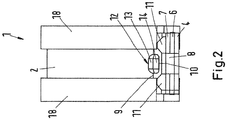
- the Fig. 1 and 2 show a clamp 1 according to a first embodiment with a clamp band 2.
- the clamp band 2 has a first circumferential end 3 with a first end leg 4.
- a second circumferential end 5 of the clamp band 2 has a second leg 6 and a tab 7.
- the tab 7 is arranged on a side facing away from the first leg 4 of the second leg 6.
- the first leg 4, the second leg 6, and the tab 7 each have a passage opening 8.
- On a clamp band 2 side facing the tab 7 has a bent end portion 9.
- the bent end portion 9 has in its axial center a recess 10 which is surrounded on both sides by stiffening beads 11.
- the recess 10 is in the assembled state of the clamp with a projection 12 into engagement, which has a first edge 13 and a second edge 14.
- the projection 12 is arranged on the clamp band 2.
- the projection 12 audibly engages in the recess 10.
- the tab 7 is held against rotation on the second leg 6. It is also protected against lifting from the second leg 6.
- the bent end portion 9 there are no sharp edges that could lead to a notch effect when acted upon by a force perpendicular to the second leg 6.
- the first leg 4 is formed by a bend 15 of the clamp band 2.
- the first leg 4 has in the region of the bend 15 at least one stiffening bead 16.
- This stiffening bead 16 is formed by a transition region 17.
- a jacket 18, which may be formed from an elastomeric material, for example EPDM, silicone, TPE, NBR or CR.
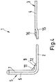
- the Fig. 1 shows the clamp 1 with a C-shaped clamp band 2.
- the C-shaped clamp band 2 encloses a receiving space such that in a closed or nearly closed state of the clamp 1, a tubular or tubular object can be held.
- the clamp 1 When the clamp 1 is opened, it can be slid over a tubular article (not shown). By squeezing and moving together the two circumferential ends 3, 5, the clamp 1 is then closed and fixed in position on the object.
- the first leg 4 is formed by a bend 15 from the clamp band 2 and extends almost straight from the clamp band 2.
- the bend 15 serves as a spacer between the clamp band 2 and a (not shown) pad to which the clamp 1 is to be attached to make room for the (in Fig. 1 not shown) jacket 18 to create.
- the bend 15 can, for example, in clamps 1 without coat 18 or if the installation requires it, also omitted.
- the second leg 6, and the 10 arranged on this tab 7 are bent approximately at right angles to the clamp band 2.
- the first leg 4, the second leg 6, and the tab 7 each have a through opening 8.
- the three passage openings 8 each overlap.
- the passage openings 8 can be provided, for example, with a circular shape, a circular ring shape or a polygonal peripheral edge. It is also possible to form one or more of the passage openings 8 as a slot.
- the passage openings 8 serve to receive holding elements, which are used to attach the clamp 1 to a base. Such holding elements can be provided for example by screws or rivets. These are then received in the passage opening 8 and are at the same time with the pad in engagement that the clamp 1 is reliably attached to this.
- Fig. 2 shows the clamp 1 dressed in a closed state in a front view with a jacket 18.
- Fig. 3 to 7 show views of the clamp 1 during its manufacturing process, as well as detailed views of some of its structural features.
- Fig. 3 the clamp 1 is shown in a bent-up state.
- the clamp band 2 is not yet bent into the intended C-shape.
- the tab 7 is not yet arranged in its position on the second leg 6.
- the right part of the Fig. 3 shows that am first circumferential end 3 of the clamp band 2 of the first leg 4 by a bend 15 the clamp band 2 is formed. In the region of the bend 15, the stiffening bead 16 is formed.
- the first leg 4 extends almost straight from the clamp band 2.
- On the first circumferential end 3 opposite portion of the clamp band 2, ie in the left part of the Fig. 3 Part of the clamp band 2 is formed to the first edge 13.
- the first flank 13 forms part of the projection 12.
- the projection 12 has the second flank 14, which opens again into the clamp band 2.
- the stiffening bead 11 is provided.
- the second leg 6 is bent at approximately right angles from the clamp band 2.
- the second leg 6 is formed integrally with the tab 7.
- the tab 7 has on its second leg 6 opposite end of the bent end portion 9.
- the bent end portion 9 is bent approximately at right angles from the tab 7. In the region of this bend stiffening beads 11 are provided.
- Fig. 4 shows the clamp 1 the Fig. 3 After the tab 7 has been bent into position on the second leg 6.
- the second leg 6 is integrally formed with the tab 7.
- the second leg 6 has at its end adjacent the tab 7 recesses, so that the material of the clamp band 2 tapers in the transition from the second leg 6 to the tab 7 back.
- the tab 7 can be bent over and arranged in the position provided for it on the side facing away from the first leg 4 of the second leg 6.
- the arrangement of the tab 7 on the second leg 6 thereby increases the flexural rigidity of the second circumferential end 5 of the clamp 1.
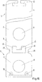
- the one-piece design of the tab 7 with the second leg 6 makes the provision of a second half part for the tab 7 superfluous. It is therefore possible in a cost and time efficient manner, the clamp band 2, as it is in Fig. 5 is shown to produce in one step, for example, a punching operation.
- Both on the second leg 6, as well as on the tab 7 stiffening beads 11 may be provided. These can be arranged on both sides of the projection 12, or on both sides of the recess 10 of the bent end portion 9. This is exemplary in Fig. 6 shown for a state of the clamp 1, in which this is not yet finally assembled shown. The tab 7 is not yet shown in its final position on the second leg 6.
- This offset of the bend 15 is formed by the transition region 17.
- the transition region 17 is not uniform over the width of the clamp band 2, and the first leg 4, is formed, but it runs in an in Fig. 7 illustrated top view V-shaped.
- the stiffening bead 16 is formed, which contributes to a stiffening of the transition region 17 and thus the bend 15.
- Fig. 7 is also shown that the tab 7 is about the bent end portion 9 by means of the recess 10 with the projection 12 is engaged. This engagement and other structural features of the projection 12 are in the Fig. 8 and 9 shown.
- Fig. 8 shows an enlarged view of the engagement of the bent end portion 9 with the projection 12.
- the recess 10 of the bent end portion 9 encloses the projection 12 in a form-fitting manner.
- the extent of the recess 10 in a circumferential direction of the clamp band 2 comprises approximately half of an extent of the projection 12 in this direction. This ensures that a disengagement of the recess 10 with the projection 12 by the tab 7 in the axial direction of the clamp band 2 acting forces is avoided.
- the projection 12 can be formed integrally with the clamp band 2. This can be done for example by way of cold forming of the clamp band 2. As a result, the first edge 13 and the second edge 14 of the projection 12 are formed. In this case, the first flank 13 opens at a more acute angle than the second flank 14 in the clamp band 2.
- the second flank 14 also has a right angle relative to the clamp band 2.
- the tab 7 can then be brought into its final position on the second leg 6 as follows.
- the tab 7 is bent in the region of the recesses between the tab 7 and the second leg 6 in the direction of the clamp band until the recess 10 opposite end of the bent end portion 9 comes to rest with the first edge 13.
- it acts on the tab 7 with a force in the direction of the second leg 6, so that the bent end portion 9 slides down on the first edge 13 in the direction of the second leg 6 until it has overcome the highest radial point of the projection 12, and the Recess 10 is disposed in a position below the second edge (ie in the direction of the second leg 6).
- the formation of a right angle to the second flank 14 relative to the clamp band 2 ensures that a disengagement of the recess 10 can be prevented with the projection 12 by the action of forces in the circumferential direction of the clamp band 2 on the tab 7.
- stiffening beads 11 may be provided, which are formed on both the second leg 6 and the tab 7. This is for example from the Fig. 1 and 2 seen.
- the formation of the stiffening beads 11 on both sides of the projection 12 thereby causes a further stiffening of the tab 7 in its position and thus a twist-proof engagement of the tab 7 on the second leg. 6
- the following materials may be considered for the clamp band 2: galvanized steel, chrome steel, chrome nickel steel, copper, brass, aluminum and magnesium alloys, as well as fiber composite materials.
- the production of the clamp 1 made of aluminum alloys is possible because you can make the clamp 1 in one piece, for example by punching.
- the supply and attachment of separate aluminum halves, on the other hand, is very problematic because of the occurrence of abrasion in an automated manufacturing process; However, this use of separate half parts can be dispensed with after the inventive production of the clamp 1.
- the Fig. 10A-F show various embodiments that may be provided for the cross section of the clamp band 2.
- the Fig. 10A shows a rectilinear cross section of the clamp band 2;
- Fig. 10B shows a clamp band 2 in cross section with a curvature and a uniform associated radius of curvature;
- Fig. 10C shows a clamp band 2 in cross-section with a uniform first radius of curvature and on the clamp band 2 two elevations 20, which are formed at a second radius of curvature, which differs from the first uniform radius of curvature of the clamp band 2.
- Fig. 10D represents a cross section of the clamp band 2, in which the two axial ends of the clamp band 2 are bent toward each other at a common, certain angle. In the left part of the Fig.
- a rectilinear trained cross-section of the clamp band 2 is shown, wherein the clamp band 2 in this case has a recess 19; this recess 19 is limited to a spatially limited area of the clamp band 2, as shown in the perspective view of the clamp band 2 in the right half of Fig. 10E evident.
- it can also be provided to form the clamp band 2 with a wave-shaped cross section.
- the curvature radii of the clamp band 2 characterizing the waveform can be identical or different.
- Such a cross section of the clamp band 2 is in Fig.10F shown.
- Fig. 11 a second embodiment of a clamp 1 is shown.
- Those constructive features of the clamp 1, which coincide with those of the first embodiment, are provided with identical reference numerals. Also applies to these features so far said accordingly for the second embodiment described below.
- a tab 71 is provided in addition to the arranged on the second leg 6 tab 7 and on the first leg 4, a tab 71 is provided.
- the bend 15 on the first leg 4 of the first embodiment is omitted here accordingly and the first leg 4 is bent as well as the second leg 6 approximately at right angles from the clamp band 2.
- the attachment of the tab 71 on the first leg 4 is done in the same way as is the case with the attachment of the tab 7 on the second leg 6.
- the tab 71 has a bent end portion 91 which is reinforced by a stiffening bead 111 in its rigidity.
- the tab 71 is brought via a corresponding recess (not shown) of its bent end portion 91 with a corresponding projection 121 on the clamp band 2 in engagement. Both structural and functional features of the tab 7, which is arranged on the second leg 6, are therefore also found correspondingly for the tab 71, which is arranged on the first leg 4.
- FIG Fig. 12 A third embodiment of the clamp 1 according to the invention is shown in FIG Fig. 12 shown. Again, identical features are provided with identical reference numerals.
- a clamp 1 is provided with a Vorfix michsvortechnik. How out Fig. 12 can be seen, the clamp 1 is identical to the clamp 1 of the first embodiment except for the Vorfix michsvorraum. The structural design of the Vorfix michsvortechnik is described below with reference to the Fig. 13 to 16 described in more detail.
- Fig. 13 shows a view of the Vorfix istsvorraum in an open and a closed state of the clamp 1. It is also a section AA shown.
- a mounting portion 21 is arranged in the end portion of the second leg 6.
- a first and a second fastening element 22, 23 protrude in the direction of the second leg 6. This makes it possible to plastically transform the fastening elements 22, 23 onto the side of the fastening section 21 facing away from the first leg 4 when the clamp 1 is brought into a closed state. This is especially true when comparing the opened ( Fig. 13 Top view below) with the closed ( Fig. 13 Top view above) state of the clamp 1 to recognize.
- the clamp 1 can thus be securely held in a closed state on the tubular object to be fastened, without the connection of the two circumferential ends 3, 5 thus produced being released again.
- the fitter of the clamp 1 can now with this attach corresponding retaining elements to the base without having to disengage the clamp with the object by loading the clamp 1, as they may occur during assembly, for example.
- the sectional view AA in the right part of the Fig. 13 shows the clamp 1 with a Vorfix istsvortechnisch in the closed state.
- Fig. 14 is the passage opening 8 exemplified as a slot.
- Fig. 15 shows a bent clamp band 2, that in contrast to the clamp band 2 of the first embodiment of the Fig. 5 is provided with the structural features of a Vorfixleitersvorraum. A first possible embodiment of these features is shown.
- this tapers in order to continue integrally in the tab 7 via a doubly formed web 25.
- the axial center of the second leg 6 of the planar attachment portion 21 is formed. This is surrounded on both sides by the gap 24, in which the first and second fastening elements 22,23 of the first leg 4 can protrude.
- FIG Fig. 16 A second embodiment of the prefixing device is shown in FIG Fig. 16 shown.
- a bent clamp band 2 is shown, which has at its second leg 6 in the axial center of a planar mounting portion 21. This is surrounded by the gap 24 and in turn is continued in the here simply executed web 25.
- the web 25 establishes the connection of the second leg 6 with the tab 7.
- the width of the web 25 may vary depending on the requirements of the clamp 1.
- first and second fastening elements 22, 23 are provided, which protrude into the gap 24 in an assembled state of the clamp 1.
Landscapes
- Engineering & Computer Science (AREA)
- General Engineering & Computer Science (AREA)
- Mechanical Engineering (AREA)
- Clamps And Clips (AREA)
- Supports For Pipes And Cables (AREA)
Claims (13)
- Collier de serrage (1), en particulier pour la fixation d'objets tubulaires à un support, avec une bande de collier (2) avec une première extrémité circonférentielle (3), qui présente une première branche (6), et une deuxième extrémité circonférentielle (5), qui présente une deuxième branche (6), et avec au moins une patte (7, 71), qui est disposée sur au moins une des branches (4, 6) sur un côté opposé à respectivement l'autre branche (6, 4), dans lequel la bande de collier (2) présente au moins une saillie (12), qui coopère avec l'au moins une patte (7, 71), caractérisé en ce que la saillie (12) présente une plus grande extension dans une direction axiale de la bande de collier (2) que dans une direction circonférentielle de la bande de collier (2).
- Collier de serrage selon la revendication 1, caractérisé en ce que la première et/ou deuxième branche (4, 6) et la patte (71, 7) disposée sur celle-ci sont réalisées d'un seul tenant.
- Collier de serrage selon l'une quelconque des revendications 1 ou 2, caractérisé en ce que l'au moins une patte (7, 71) présente respectivement une section d'extrémité repliée (9, 91), qui est disposée sur un côté de la patte (7, 71) tourné vers la bande de collier (2).
- Collier de serrage selon la revendication 3, caractérisé en ce que la respectivement une section d'extrémité repliée (9, 91) est tournée dans une direction opposée à la branche (4, 6), sur laquelle la patte (7, 71) présentant la section d'extrémité repliée (9, 91) est disposée, et présente un évidement (10).
- Collier de serrage selon la revendication 4, caractérisé en ce que l'évidement (10) respectif et la saillie (12) qui lui est associée sont en prise l'un avec l'autre par correspondance de forme.
- Collier de serrage selon la revendication 4 ou 5, caractérisé en ce qu'une extension de l'évidement (10) dans une direction circonférentielle de la bande de collier (2) comprend au moins la moitié d'une extension de la saillie (12) dans cette direction.
- Collier de serrage selon l'une quelconque des revendications 3 à 6, caractérisé en ce qu'une extension radiale de la saillie (12) est adaptée à une extension radiale de la section d'extrémité repliée (9, 91) respective.
- Collier de serrage selon l'une quelconque des revendications 1 à 7, caractérisé en ce que la saillie (12) présente un premier (13) et un deuxième flanc (14) dans une direction circonférentielle de la bande de collier (12), dans lequel le premier flanc (13) débouche dans la bande de collier (2) en un angle plus aigu que le deuxième flanc (14).
- Collier de serrage selon la revendication 8, caractérisé en ce que le deuxième flanc (14) présente un angle droit par rapport à la bande de collier (2).
- Collier de serrage selon l'une quelconque des revendications 3 à 9, caractérisé en ce que la première et/ou la deuxième branche (4, 6) et la patte (71, 7) disposée sur celle-ci présentent au moins une nervure de renfort (111, 11) au niveau de leur section d'extrémité repliée (91, 9).
- Collier de serrage selon la revendication 10, caractérisé en ce que la première et/ou deuxième branche (6) et la patte (71, 7) disposée sur celle-ci présentent au moins une nervure de renfort (111, 11) de chaque côté de l'évidement (10) de leur section d'extrémité repliée (91, 9).
- Collier de serrage selon l'une quelconque des revendications 1 à 11, caractérisé en ce que la patte (7) est disposée seulement sur un côté de la deuxième branche (6) opposé à première branche (4) et la première branche (4) est formée par un coude de la bande de collier (2), qui présente au moins une nervure de renfort (16).
- Collier de serrage selon l'une quelconque des revendications 1 à 12, caractérisé en ce que la première branche (4) présente à l'état ouvert du collier de serrage (1) au moins un élément de fixation (22, 23) faisant saillie en direction de la deuxième branche (6) et la deuxième branche (6) présente une section de fixation (21), qui peut être introduite dans un espace vide (24) entre l'élément de fixation (22, 23) et une zone voisine de la première branche (4) opposée à l'élément de fixation (22, 23) et qu'à l'état fermé du collier de serrage (1) l'au moins un élément de fixation (22, 23) est déformé plastiquement sur le côté de la section de fixation (21) opposé à la première branche (4).
Priority Applications (4)
| Application Number | Priority Date | Filing Date | Title |
|---|---|---|---|
| PL18201364T PL3450811T3 (pl) | 2014-05-27 | 2015-05-27 | Opaska zaciskowa |
| RS20190285A RS58408B1 (sr) | 2014-05-27 | 2015-05-27 | Obujmica |
| PL15724326T PL3149375T3 (pl) | 2014-05-27 | 2015-05-27 | Opaska zaciskowa |
| EP18201364.9A EP3450811B1 (fr) | 2014-05-27 | 2015-05-27 | Collier de serrage |
Applications Claiming Priority (2)
| Application Number | Priority Date | Filing Date | Title |
|---|---|---|---|
| DE102014107442.4A DE102014107442A1 (de) | 2014-05-27 | 2014-05-27 | Schelle |
| PCT/EP2015/061706 WO2015181236A1 (fr) | 2014-05-27 | 2015-05-27 | Collier |
Related Child Applications (2)
| Application Number | Title | Priority Date | Filing Date |
|---|---|---|---|
| EP18201364.9A Division EP3450811B1 (fr) | 2014-05-27 | 2015-05-27 | Collier de serrage |
| EP18201364.9A Division-Into EP3450811B1 (fr) | 2014-05-27 | 2015-05-27 | Collier de serrage |
Publications (2)
| Publication Number | Publication Date |
|---|---|
| EP3149375A1 EP3149375A1 (fr) | 2017-04-05 |
| EP3149375B1 true EP3149375B1 (fr) | 2018-12-05 |
Family
ID=53264675
Family Applications (2)
| Application Number | Title | Priority Date | Filing Date |
|---|---|---|---|
| EP18201364.9A Active EP3450811B1 (fr) | 2014-05-27 | 2015-05-27 | Collier de serrage |
| EP15724326.2A Active EP3149375B1 (fr) | 2014-05-27 | 2015-05-27 | Collier de serrage |
Family Applications Before (1)
| Application Number | Title | Priority Date | Filing Date |
|---|---|---|---|
| EP18201364.9A Active EP3450811B1 (fr) | 2014-05-27 | 2015-05-27 | Collier de serrage |
Country Status (12)
| Country | Link |
|---|---|
| US (1) | US10487862B2 (fr) |
| EP (2) | EP3450811B1 (fr) |
| JP (1) | JP6414856B2 (fr) |
| KR (1) | KR101963713B1 (fr) |
| CN (1) | CN106471301B (fr) |
| DE (1) | DE102014107442A1 (fr) |
| ES (2) | ES2713050T3 (fr) |
| HU (1) | HUE043734T2 (fr) |
| PL (2) | PL3450811T3 (fr) |
| RS (1) | RS58408B1 (fr) |
| TR (1) | TR201900892T4 (fr) |
| WO (1) | WO2015181236A1 (fr) |
Families Citing this family (6)
| Publication number | Priority date | Publication date | Assignee | Title |
|---|---|---|---|---|
| DE102017103079A1 (de) * | 2017-02-15 | 2018-08-16 | Norma Germany Gmbh | Schelle |
| US10931090B2 (en) | 2017-03-07 | 2021-02-23 | Kidde Technologies, Inc. | Mount with clip |
| DE102017118047B4 (de) * | 2017-08-08 | 2025-03-27 | Norma Germany Gmbh | Schelle zum Befestigen eines rohr- oder schlauchförmigen Gegenstands |
| JP7543919B2 (ja) * | 2021-01-07 | 2024-09-03 | トヨタ自動車株式会社 | 車両用ペダル組付け構造 |
| FR3120391B1 (fr) * | 2021-03-03 | 2023-11-03 | Safran Aircraft Engines | Systeme de maintien et de fixation d’un harnais electrique pour une turbomachine d’aeronef |
| USD1072589S1 (en) * | 2023-12-18 | 2025-04-29 | Jingqing DU | Trimmer line |
Family Cites Families (27)
| Publication number | Priority date | Publication date | Assignee | Title |
|---|---|---|---|---|
| USRE22846E (en) * | 1947-02-25 | Supporting clip | ||
| GB578891A (en) * | 1943-03-24 | 1946-07-16 | Adel Prec Products Corp | Conduit supporting clip |
| US2409772A (en) * | 1944-05-13 | 1946-10-22 | Adel Prec Products Corp | Adjustable harness clip |
| US2655703A (en) * | 1951-10-08 | 1953-10-20 | Tinnerman Products Inc | Clamp |
| US2941768A (en) * | 1958-09-22 | 1960-06-21 | Robert L Brown | Tubing fastener |
| US3144695A (en) * | 1961-04-24 | 1964-08-18 | Gilbert G Budwig | Mounting device |
| US3376004A (en) * | 1966-06-16 | 1968-04-02 | Mc Donnell Douglas Corp | Snap clamp |
| US3460788A (en) * | 1967-10-02 | 1969-08-12 | Mc Donnell Douglas Corp | Clamp latch |
| US3995795A (en) * | 1975-03-24 | 1976-12-07 | Mcdonnell Douglas Corporation | Wiring anti-chafe support device |
| JPS58122088U (ja) * | 1982-02-12 | 1983-08-19 | トヨタ自動車株式会社 | 留め具 |
| US4441677A (en) * | 1982-04-02 | 1984-04-10 | Ta Mfg., Inc. | Clamp device |
| DE9214700U1 (de) * | 1992-08-11 | 1993-03-25 | Mächtle-Wöhler, Margot, 7000 Stuttgart | Rohrschelle |
| US5377940A (en) * | 1993-03-19 | 1995-01-03 | Bell Helicopter Textron Inc. | Self-restraining loop clamp |
| JP2539721Y2 (ja) * | 1993-10-18 | 1997-06-25 | 宮川工業株式会社 | 配管用支持具 |
| DE19716632A1 (de) * | 1997-04-21 | 1998-10-22 | Fischer Artur Werke Gmbh | Rohrschelle |
| DE19818179A1 (de) * | 1998-04-23 | 1999-11-04 | Rasmussen Gmbh | Schelle zum Einspannen langgestreckter Gegenstände |
| US6443403B1 (en) * | 2000-09-11 | 2002-09-03 | Panduit Corp. | Cable routing clamp and method of application |
| DE202004011936U1 (de) * | 2004-07-29 | 2004-09-30 | Aba Of Sweden Ab | Schlauchschelle |
| SE528956C2 (sv) * | 2005-09-06 | 2007-03-20 | Aba Sweden Ab | Fixering för slangklämma |
| DE102006020407B3 (de) * | 2006-05-03 | 2008-01-24 | Norma Germany Gmbh | Schelle zum Befestigen eines rohr- oder schlauchförmigen Gegenstandes |
| DE102006048336B4 (de) * | 2006-10-12 | 2013-07-04 | Norma Germany Gmbh | Schlauchschelle |
| JP4706660B2 (ja) | 2007-04-10 | 2011-06-22 | 株式会社デンソー | 還元剤供給装置 |
| DE102008010902A1 (de) * | 2008-02-23 | 2009-09-10 | Schulte, Frank | Rohrschelle |
| US20120012716A1 (en) * | 2008-04-16 | 2012-01-19 | Chin-Hsiung Lien | Self-secure mount for tubular object |
| DE102009023613A1 (de) * | 2009-06-02 | 2010-01-21 | Daimler Ag | Schelle zur Befestigung von zumindest einer Schlauch- und/oder Rohrleitung und/oder eines Kabels |
| ITTO20090584A1 (it) * | 2009-07-29 | 2011-01-30 | Dytech Dynamic Fluid Tech Spa | Fascetta portatubi |
| US9829119B2 (en) * | 2015-12-14 | 2017-11-28 | Amphenol Corporation | Monolithic thermoplastic P-clamp with cushion and locking mechanism |
-
2014
- 2014-05-27 DE DE102014107442.4A patent/DE102014107442A1/de active Pending
-
2015
- 2015-05-27 KR KR1020167036395A patent/KR101963713B1/ko active Active
- 2015-05-27 ES ES15724326T patent/ES2713050T3/es active Active
- 2015-05-27 WO PCT/EP2015/061706 patent/WO2015181236A1/fr not_active Ceased
- 2015-05-27 US US15/314,473 patent/US10487862B2/en active Active
- 2015-05-27 RS RS20190285A patent/RS58408B1/sr unknown
- 2015-05-27 JP JP2016568026A patent/JP6414856B2/ja active Active
- 2015-05-27 EP EP18201364.9A patent/EP3450811B1/fr active Active
- 2015-05-27 ES ES18201364T patent/ES2835339T3/es active Active
- 2015-05-27 PL PL18201364T patent/PL3450811T3/pl unknown
- 2015-05-27 PL PL15724326T patent/PL3149375T3/pl unknown
- 2015-05-27 EP EP15724326.2A patent/EP3149375B1/fr active Active
- 2015-05-27 TR TR2019/00892T patent/TR201900892T4/tr unknown
- 2015-05-27 CN CN201580027682.8A patent/CN106471301B/zh active Active
- 2015-05-27 HU HUE15724326A patent/HUE043734T2/hu unknown
Non-Patent Citations (1)
| Title |
|---|
| None * |
Also Published As
| Publication number | Publication date |
|---|---|
| ES2713050T3 (es) | 2019-05-17 |
| DE102014107442A1 (de) | 2015-12-03 |
| US10487862B2 (en) | 2019-11-26 |
| KR20170012421A (ko) | 2017-02-02 |
| EP3450811B1 (fr) | 2020-09-09 |
| CN106471301A (zh) | 2017-03-01 |
| HUE043734T2 (hu) | 2019-09-30 |
| WO2015181236A1 (fr) | 2015-12-03 |
| EP3149375A1 (fr) | 2017-04-05 |
| KR101963713B1 (ko) | 2019-03-29 |
| TR201900892T4 (tr) | 2019-02-21 |
| CN106471301B (zh) | 2020-06-30 |
| EP3450811A1 (fr) | 2019-03-06 |
| JP2017522505A (ja) | 2017-08-10 |
| US20170191512A1 (en) | 2017-07-06 |
| ES2835339T3 (es) | 2021-06-22 |
| RS58408B1 (sr) | 2019-04-30 |
| JP6414856B2 (ja) | 2018-10-31 |
| PL3149375T3 (pl) | 2019-06-28 |
| PL3450811T3 (pl) | 2021-04-06 |
Similar Documents
| Publication | Publication Date | Title |
|---|---|---|
| EP3149375B1 (fr) | Collier de serrage | |
| EP1852643B1 (fr) | Collier destiné à la fixation d'un objet tubulaire | |
| EP1979193B1 (fr) | Dispositif de fixation destiné à des pièces de véhicules à moteur | |
| DE3424675C2 (de) | Schlauchkupplung | |
| EP3423743B1 (fr) | Collier profilé comprenant un élément d'étanchéité et ensemble de liaison de conduites comprenant un collier profilé de ce type | |
| EP3612698B1 (fr) | Charnière pour boîtier d'armoire de commande ainsi que boîtier d'armoire de commande et procédé de montage correspondants | |
| WO2007104530A1 (fr) | Élément de fixation, outil de montage et ensemble de montage | |
| DE102009011864A1 (de) | Verbindungsanordnung mit einem ersten Rohrstutzen und einem zweiten Rohrstutzen sowie Verriegelungsringanordnung für eine derartige Verbindungsanordnung | |
| DE19650675A1 (de) | Profilschelle | |
| EP0738850A1 (fr) | Raccord pour tuyaux | |
| DE102017125722A1 (de) | Verbinder mit verbessertem Montageablauf | |
| EP2615346A2 (fr) | Collier à bande élastique | |
| DE102014102662A1 (de) | Steckverbindung für Fluid-Leitungen und Halteteil für eine derartige Steckverbindung | |
| EP1245889B1 (fr) | Collier de serrage | |
| DE102013100772A1 (de) | Steckverbindung für Fluid-Leitungen und Halteteil für eine derartige Steckverbindung | |
| EP2261544B1 (fr) | Anneau de fixation | |
| EP3380771B1 (fr) | Collier de serrage | |
| DE102007005475A1 (de) | Befestigungseinheit mit einem an einem Trägerelement anbringbaren Befestigungselement | |
| EP1852304A1 (fr) | Dispositif de fixation doté d'un cliquet amovible | |
| DE102016101466B4 (de) | Fahrradbremse | |
| EP2754803B1 (fr) | Crémone de fenêtre ou de porte et tringle pour une telle crémone | |
| EP2594165B1 (fr) | Support pour la fixation par serrage d'un objet, notamment d'un dispositif de tensionnement d'un cable pour un dispositif de pare-soleil et/ou de protection contre la vue, sur un cadre de fenêtre ou de porte | |
| DE102018101153A1 (de) | Rahmen für einen Kabelschacht | |
| DE102010047991A1 (de) | Befestigungssystem eines Kabelübergangsgerätes in einem Mast | |
| EP1939538A2 (fr) | Hotte aspirante équipée d'une première partie de boîtier sur laquelle est maintenue de façon détachable une seconde partie de boîtier |
Legal Events
| Date | Code | Title | Description |
|---|---|---|---|
| STAA | Information on the status of an ep patent application or granted ep patent |
Free format text: STATUS: THE INTERNATIONAL PUBLICATION HAS BEEN MADE |
|
| PUAI | Public reference made under article 153(3) epc to a published international application that has entered the european phase |
Free format text: ORIGINAL CODE: 0009012 |
|
| STAA | Information on the status of an ep patent application or granted ep patent |
Free format text: STATUS: REQUEST FOR EXAMINATION WAS MADE |
|
| 17P | Request for examination filed |
Effective date: 20161128 |
|
| AK | Designated contracting states |
Kind code of ref document: A1 Designated state(s): AL AT BE BG CH CY CZ DE DK EE ES FI FR GB GR HR HU IE IS IT LI LT LU LV MC MK MT NL NO PL PT RO RS SE SI SK SM TR |
|
| AX | Request for extension of the european patent |
Extension state: BA ME |
|
| DAV | Request for validation of the european patent (deleted) | ||
| DAX | Request for extension of the european patent (deleted) | ||
| RIC1 | Information provided on ipc code assigned before grant |
Ipc: F16B 2/06 20060101ALI20180615BHEP Ipc: F16L 3/123 20060101AFI20180615BHEP Ipc: F16L 55/035 20060101ALI20180615BHEP |
|
| GRAP | Despatch of communication of intention to grant a patent |
Free format text: ORIGINAL CODE: EPIDOSNIGR1 |
|
| STAA | Information on the status of an ep patent application or granted ep patent |
Free format text: STATUS: GRANT OF PATENT IS INTENDED |
|
| INTG | Intention to grant announced |
Effective date: 20180731 |
|
| GRAS | Grant fee paid |
Free format text: ORIGINAL CODE: EPIDOSNIGR3 |
|
| GRAA | (expected) grant |
Free format text: ORIGINAL CODE: 0009210 |
|
| STAA | Information on the status of an ep patent application or granted ep patent |
Free format text: STATUS: THE PATENT HAS BEEN GRANTED |
|
| AK | Designated contracting states |
Kind code of ref document: B1 Designated state(s): AL AT BE BG CH CY CZ DE DK EE ES FI FR GB GR HR HU IE IS IT LI LT LU LV MC MK MT NL NO PL PT RO RS SE SI SK SM TR |
|
| REG | Reference to a national code |
Ref country code: GB Ref legal event code: FG4D Free format text: NOT ENGLISH |
|
| REG | Reference to a national code |
Ref country code: CH Ref legal event code: EP |
|
| REG | Reference to a national code |
Ref country code: AT Ref legal event code: REF Ref document number: 1073494 Country of ref document: AT Kind code of ref document: T Effective date: 20181215 |
|
| REG | Reference to a national code |
Ref country code: IE Ref legal event code: FG4D Free format text: LANGUAGE OF EP DOCUMENT: GERMAN |
|
| REG | Reference to a national code |
Ref country code: DE Ref legal event code: R096 Ref document number: 502015007107 Country of ref document: DE |
|
| REG | Reference to a national code |
Ref country code: RO Ref legal event code: EPE |
|
| REG | Reference to a national code |
Ref country code: NL Ref legal event code: FP |
|
| REG | Reference to a national code |
Ref country code: SE Ref legal event code: TRGR |
|
| REG | Reference to a national code |
Ref country code: CH Ref legal event code: NV Representative=s name: ISLER AND PEDRAZZINI AG, CH |
|
| REG | Reference to a national code |
Ref country code: LT Ref legal event code: MG4D |
|
| PG25 | Lapsed in a contracting state [announced via postgrant information from national office to epo] |
Ref country code: FI Free format text: LAPSE BECAUSE OF FAILURE TO SUBMIT A TRANSLATION OF THE DESCRIPTION OR TO PAY THE FEE WITHIN THE PRESCRIBED TIME-LIMIT Effective date: 20181205 Ref country code: LV Free format text: LAPSE BECAUSE OF FAILURE TO SUBMIT A TRANSLATION OF THE DESCRIPTION OR TO PAY THE FEE WITHIN THE PRESCRIBED TIME-LIMIT Effective date: 20181205 Ref country code: LT Free format text: LAPSE BECAUSE OF FAILURE TO SUBMIT A TRANSLATION OF THE DESCRIPTION OR TO PAY THE FEE WITHIN THE PRESCRIBED TIME-LIMIT Effective date: 20181205 Ref country code: HR Free format text: LAPSE BECAUSE OF FAILURE TO SUBMIT A TRANSLATION OF THE DESCRIPTION OR TO PAY THE FEE WITHIN THE PRESCRIBED TIME-LIMIT Effective date: 20181205 Ref country code: NO Free format text: LAPSE BECAUSE OF FAILURE TO SUBMIT A TRANSLATION OF THE DESCRIPTION OR TO PAY THE FEE WITHIN THE PRESCRIBED TIME-LIMIT Effective date: 20190305 Ref country code: BG Free format text: LAPSE BECAUSE OF FAILURE TO SUBMIT A TRANSLATION OF THE DESCRIPTION OR TO PAY THE FEE WITHIN THE PRESCRIBED TIME-LIMIT Effective date: 20190305 |
|
| REG | Reference to a national code |
Ref country code: ES Ref legal event code: FG2A Ref document number: 2713050 Country of ref document: ES Kind code of ref document: T3 Effective date: 20190517 |
|
| PG25 | Lapsed in a contracting state [announced via postgrant information from national office to epo] |
Ref country code: GR Free format text: LAPSE BECAUSE OF FAILURE TO SUBMIT A TRANSLATION OF THE DESCRIPTION OR TO PAY THE FEE WITHIN THE PRESCRIBED TIME-LIMIT Effective date: 20190306 Ref country code: AL Free format text: LAPSE BECAUSE OF FAILURE TO SUBMIT A TRANSLATION OF THE DESCRIPTION OR TO PAY THE FEE WITHIN THE PRESCRIBED TIME-LIMIT Effective date: 20181205 |
|
| PG25 | Lapsed in a contracting state [announced via postgrant information from national office to epo] |
Ref country code: PT Free format text: LAPSE BECAUSE OF FAILURE TO SUBMIT A TRANSLATION OF THE DESCRIPTION OR TO PAY THE FEE WITHIN THE PRESCRIBED TIME-LIMIT Effective date: 20190405 |
|
| REG | Reference to a national code |
Ref country code: SK Ref legal event code: T3 Ref document number: E 30784 Country of ref document: SK |
|
| PG25 | Lapsed in a contracting state [announced via postgrant information from national office to epo] |
Ref country code: SM Free format text: LAPSE BECAUSE OF FAILURE TO SUBMIT A TRANSLATION OF THE DESCRIPTION OR TO PAY THE FEE WITHIN THE PRESCRIBED TIME-LIMIT Effective date: 20181205 Ref country code: EE Free format text: LAPSE BECAUSE OF FAILURE TO SUBMIT A TRANSLATION OF THE DESCRIPTION OR TO PAY THE FEE WITHIN THE PRESCRIBED TIME-LIMIT Effective date: 20181205 Ref country code: IS Free format text: LAPSE BECAUSE OF FAILURE TO SUBMIT A TRANSLATION OF THE DESCRIPTION OR TO PAY THE FEE WITHIN THE PRESCRIBED TIME-LIMIT Effective date: 20190405 |
|
| REG | Reference to a national code |
Ref country code: DE Ref legal event code: R097 Ref document number: 502015007107 Country of ref document: DE |
|
| REG | Reference to a national code |
Ref country code: HU Ref legal event code: AG4A Ref document number: E043734 Country of ref document: HU |
|
| PLBE | No opposition filed within time limit |
Free format text: ORIGINAL CODE: 0009261 |
|
| STAA | Information on the status of an ep patent application or granted ep patent |
Free format text: STATUS: NO OPPOSITION FILED WITHIN TIME LIMIT |
|
| PG25 | Lapsed in a contracting state [announced via postgrant information from national office to epo] |
Ref country code: SI Free format text: LAPSE BECAUSE OF FAILURE TO SUBMIT A TRANSLATION OF THE DESCRIPTION OR TO PAY THE FEE WITHIN THE PRESCRIBED TIME-LIMIT Effective date: 20181205 Ref country code: DK Free format text: LAPSE BECAUSE OF FAILURE TO SUBMIT A TRANSLATION OF THE DESCRIPTION OR TO PAY THE FEE WITHIN THE PRESCRIBED TIME-LIMIT Effective date: 20181205 |
|
| 26N | No opposition filed |
Effective date: 20190906 |
|
| PG25 | Lapsed in a contracting state [announced via postgrant information from national office to epo] |
Ref country code: MC Free format text: LAPSE BECAUSE OF FAILURE TO SUBMIT A TRANSLATION OF THE DESCRIPTION OR TO PAY THE FEE WITHIN THE PRESCRIBED TIME-LIMIT Effective date: 20181205 |
|
| PG25 | Lapsed in a contracting state [announced via postgrant information from national office to epo] |
Ref country code: IE Free format text: LAPSE BECAUSE OF NON-PAYMENT OF DUE FEES Effective date: 20190527 |
|
| PG25 | Lapsed in a contracting state [announced via postgrant information from national office to epo] |
Ref country code: CY Free format text: LAPSE BECAUSE OF FAILURE TO SUBMIT A TRANSLATION OF THE DESCRIPTION OR TO PAY THE FEE WITHIN THE PRESCRIBED TIME-LIMIT Effective date: 20181205 |
|
| PG25 | Lapsed in a contracting state [announced via postgrant information from national office to epo] |
Ref country code: MT Free format text: LAPSE BECAUSE OF FAILURE TO SUBMIT A TRANSLATION OF THE DESCRIPTION OR TO PAY THE FEE WITHIN THE PRESCRIBED TIME-LIMIT Effective date: 20181205 |
|
| PG25 | Lapsed in a contracting state [announced via postgrant information from national office to epo] |
Ref country code: MK Free format text: LAPSE BECAUSE OF FAILURE TO SUBMIT A TRANSLATION OF THE DESCRIPTION OR TO PAY THE FEE WITHIN THE PRESCRIBED TIME-LIMIT Effective date: 20181205 |
|
| PGFP | Annual fee paid to national office [announced via postgrant information from national office to epo] |
Ref country code: NL Payment date: 20250526 Year of fee payment: 11 |
|
| PGFP | Annual fee paid to national office [announced via postgrant information from national office to epo] |
Ref country code: PL Payment date: 20250505 Year of fee payment: 11 Ref country code: DE Payment date: 20250529 Year of fee payment: 11 |
|
| PGFP | Annual fee paid to national office [announced via postgrant information from national office to epo] |
Ref country code: GB Payment date: 20250527 Year of fee payment: 11 Ref country code: ES Payment date: 20250602 Year of fee payment: 11 |
|
| PGFP | Annual fee paid to national office [announced via postgrant information from national office to epo] |
Ref country code: HU Payment date: 20250515 Year of fee payment: 11 Ref country code: RS Payment date: 20250501 Year of fee payment: 11 |
|
| PGFP | Annual fee paid to national office [announced via postgrant information from national office to epo] |
Ref country code: LU Payment date: 20250527 Year of fee payment: 11 Ref country code: BE Payment date: 20250527 Year of fee payment: 11 Ref country code: IT Payment date: 20250521 Year of fee payment: 11 |
|
| PGFP | Annual fee paid to national office [announced via postgrant information from national office to epo] |
Ref country code: FR Payment date: 20250526 Year of fee payment: 11 |
|
| PGFP | Annual fee paid to national office [announced via postgrant information from national office to epo] |
Ref country code: CH Payment date: 20250601 Year of fee payment: 11 |
|
| PGFP | Annual fee paid to national office [announced via postgrant information from national office to epo] |
Ref country code: RO Payment date: 20250506 Year of fee payment: 11 Ref country code: AT Payment date: 20250505 Year of fee payment: 11 |
|
| PGFP | Annual fee paid to national office [announced via postgrant information from national office to epo] |
Ref country code: TR Payment date: 20250515 Year of fee payment: 11 Ref country code: SK Payment date: 20250505 Year of fee payment: 11 |
|
| PGFP | Annual fee paid to national office [announced via postgrant information from national office to epo] |
Ref country code: CZ Payment date: 20250507 Year of fee payment: 11 |
|
| PGFP | Annual fee paid to national office [announced via postgrant information from national office to epo] |
Ref country code: SE Payment date: 20250527 Year of fee payment: 11 |