EP3149383B1 - Raccord enfichable pour conduites de fluide, muni d'une douille d'adaptation intérieure - Google Patents
Raccord enfichable pour conduites de fluide, muni d'une douille d'adaptation intérieure Download PDFInfo
- Publication number
- EP3149383B1 EP3149383B1 EP15726599.2A EP15726599A EP3149383B1 EP 3149383 B1 EP3149383 B1 EP 3149383B1 EP 15726599 A EP15726599 A EP 15726599A EP 3149383 B1 EP3149383 B1 EP 3149383B1
- Authority
- EP
- European Patent Office
- Prior art keywords
- latching
- connector
- sleeve
- adapter sleeve
- section
- Prior art date
- Legal status (The legal status is an assumption and is not a legal conclusion. Google has not performed a legal analysis and makes no representation as to the accuracy of the status listed.)
- Active
Links
Images


Classifications
-
- F—MECHANICAL ENGINEERING; LIGHTING; HEATING; WEAPONS; BLASTING
- F16—ENGINEERING ELEMENTS AND UNITS; GENERAL MEASURES FOR PRODUCING AND MAINTAINING EFFECTIVE FUNCTIONING OF MACHINES OR INSTALLATIONS; THERMAL INSULATION IN GENERAL
- F16L—PIPES; JOINTS OR FITTINGS FOR PIPES; SUPPORTS FOR PIPES, CABLES OR PROTECTIVE TUBING; MEANS FOR THERMAL INSULATION IN GENERAL
- F16L37/00—Couplings of the quick-acting type
- F16L37/24—Couplings of the quick-acting type in which the connection is made by inserting one member axially into the other and rotating it to a limited extent, e.g. with bayonet-action
- F16L37/244—Couplings of the quick-acting type in which the connection is made by inserting one member axially into the other and rotating it to a limited extent, e.g. with bayonet-action the coupling being co-axial with the pipe
- F16L37/248—Bayonet-type couplings
-
- F—MECHANICAL ENGINEERING; LIGHTING; HEATING; WEAPONS; BLASTING
- F16—ENGINEERING ELEMENTS AND UNITS; GENERAL MEASURES FOR PRODUCING AND MAINTAINING EFFECTIVE FUNCTIONING OF MACHINES OR INSTALLATIONS; THERMAL INSULATION IN GENERAL
- F16L—PIPES; JOINTS OR FITTINGS FOR PIPES; SUPPORTS FOR PIPES, CABLES OR PROTECTIVE TUBING; MEANS FOR THERMAL INSULATION IN GENERAL
- F16L37/00—Couplings of the quick-acting type
- F16L37/08—Couplings of the quick-acting type in which the connection between abutting or axially overlapping ends is maintained by locking members
- F16L37/084—Couplings of the quick-acting type in which the connection between abutting or axially overlapping ends is maintained by locking members combined with automatic locking
- F16L37/098—Couplings of the quick-acting type in which the connection between abutting or axially overlapping ends is maintained by locking members combined with automatic locking by means of flexible hooks
- F16L37/0985—Couplings of the quick-acting type in which the connection between abutting or axially overlapping ends is maintained by locking members combined with automatic locking by means of flexible hooks the flexible hook extending radially inwardly from an outer part and engaging a bead, recess or the like on an inner part
-
- F—MECHANICAL ENGINEERING; LIGHTING; HEATING; WEAPONS; BLASTING
- F16—ENGINEERING ELEMENTS AND UNITS; GENERAL MEASURES FOR PRODUCING AND MAINTAINING EFFECTIVE FUNCTIONING OF MACHINES OR INSTALLATIONS; THERMAL INSULATION IN GENERAL
- F16L—PIPES; JOINTS OR FITTINGS FOR PIPES; SUPPORTS FOR PIPES, CABLES OR PROTECTIVE TUBING; MEANS FOR THERMAL INSULATION IN GENERAL
- F16L37/00—Couplings of the quick-acting type
- F16L37/08—Couplings of the quick-acting type in which the connection between abutting or axially overlapping ends is maintained by locking members
- F16L37/084—Couplings of the quick-acting type in which the connection between abutting or axially overlapping ends is maintained by locking members combined with automatic locking
Definitions
- the present invention relates to a connector according to the preamble of claim 1.
- a connector of the prior art is from DE 10 2011 084 988 known.
- the form-fitting means are formed on the outside of the free end of the latching arms.
- the latching cams are also arranged on the underside of these latching arms, with the latching cams being located within the socket section.
- this arrangement and design of the form-fitting elements and the latching cams necessitate a relatively long construction of the sleeve section and, moreover, there is a relatively large cutout in the wall of the sleeve section, so that the latching arms are unprotected and dirt can also easily penetrate into the sleeve section.
- the connecting unit made up of plug connector and mating plug connector which is known from this publication, has additional holding elements in order to ensure protection against rotation.
- a plug-in coupling has a receiving part and a securing part.
- a plug-in part can be connected to the receiving part by means of a rear locking piece of the securing part.
- the securing part has an annular sleeve on which the rear locking pieces and a blocking piece are attached via a respective spring bar.
- the blocking pieces are after Insertion of the male part is blocked by the male part radially inward so that it faces an abutment wall with an abutment wall.
- each rear locking piece of a cover wall is covered, so that access to each blocking piece from the outside is prevented.
- the spring bars for holding the rear latching pieces for holding the plug-in part are angled to a longitudinal center axis of the receiving part or the securing part.
- the invention is based on the object, starting from a connector of the type mentioned, to provide a connector which, regardless of the housing material and even in cramped installation conditions, ensures full elasticity and perfect functioning of the locking means and has a compact design and a allows a protected arrangement of the locking arms.
- the latching means are not part of the housing, but the latching means are formed on the separate part of the adapter sleeve, which is inserted into the housing. This means that different materials can be used for the housing and the adapter sleeve.
- the adapter sleeve sits in the housing in a manner that is essentially protected around the circumference, so that its function cannot be significantly impaired by other adjacent housings.
- the form-fitting elements in the inserted state engage in recesses in the peripheral wall of the sleeve section in a form-fitting manner with a locking effect makes it possible for the adapter sleeve to be designed to be relatively short and compact.
- the positive-locking elements according to the invention ensure both an axial fixation and, in particular, a circumferential fixation of the adapter sleeve in the socket section. Due to the form fit in the axial direction, the adapter sleeve cannot be loosened by tensile stress and twisting of the adapter sleeve is also avoided by a form fit according to the invention in the circumferential direction.
- the adapter sleeve has an annular collar running on the circumference of its through-opening at its rear opening edge, viewed in the direction of insertion, which is arranged outside the sleeve section when the adapter sleeve is inserted, with the first locking cams likewise running outside the sleeve section.
- latching arms offset by 180° from one another are formed on the adapter sleeve, and there are actuating projections protruding radially outwards in relation to the longitudinal center axis at the free ends of the latching arms.
- This design enables the plugged-in connector to be released by means of a release tool, in particular a fork-shaped release tool, with the fork prongs being inserted into the insertion opening and the latching arms being able to be brought out of engagement with their latching cams from a latching groove of the mating connector by moving the release tool perpendicularly to the longitudinal center axis.
- a release tool in particular a fork-shaped release tool
- the annular collar is separated from the adapter sleeve by circumferential gap sections between its latching arms, and the annular collar surrounds the latching arms in the area of the first latching cams on the outside and is connected to them in the area of the latching cams and the annular collar in the middle between the Locking arms has deformation sections which are deformable under a force directed radially to the longitudinal center axis in such a way that a radially outward spreading of the locking arms is generated in such a way that the first locking cams assume their release position. This enables the plugged-in mating connector to be detached by hand.
- the thickness of the latching arms is less than the wall thickness of the adapter sleeve, so that a step surface running radially in the direction of the longitudinal central axis is formed between an outer circumference of the wall of the adapter sleeve and the latching arms.
- the radial height of the step surface and the length of the locking arms within the sleeve section are dimensioned in such a way that a radially outward spring deflection of the locking cams is given such that a radial distance between the radially outwardly spread locking cams is greater than or equal to an inner diameter of the adapter sleeve and /or is greater than/equal to the outer diameter of the plug shank of the mating connector.
- the outside diameter of the annular collar is equal to the outside diameter of the socket section.
- the radial spacing of the angled extensions on their outer surfaces is equal to the outer diameter of the socket section.
- an outer diameter of the annular collar in the area of the locking cams is equal to the outer diameter of the socket section.
- the latching arms in the area of the latching cams can be bent outwards by the plugged-in connector, so that the latching arms with the angled extensions or the annular collar protrude radially against the outer circumference of the socket section during the plugging process in the region of the latching cams, as a result An insertion control is given, since they only spring back after snapping into the locking groove of the plug shank of the mating connector, thus indicating that the insertion process is complete.
- a peripheral seal is arranged in the insertion direction in front of the adapter sleeve in the through opening of the sleeve section for sealing a peripheral gap between an inner wall of the sleeve section and the plug shank of a mating connector. It is advantageous here if an annular shoulder is formed in the socket section at the transition from the diameter-enlarged section of the socket section to the through-channel for the peripheral seal to rest and the peripheral seal is chambered between the annular shoulder and an end face of the adapter sleeve.
- This arrangement of the peripheral seal according to the invention makes it possible that undercuts do not have to be formed either in the connector or in the mating connector in order to achieve chambering of the peripheral seal.
- the peripheral seal sits protected inside the socket section.
- the connecting section of the housing opposite the socket section is designed as a connecting pin, the connecting pin having a peripheral seal in the area of its free end in a circumferential groove and in the area opposite the free end of the connecting pin there are several seals in the direction of the free end extending, parallel to the longitudinal center axis of the connecting pin extending latching webs are arranged, which are distributed on the circumference of the connecting pin spaced evenly.
- latching webs there are preferably two diametrically opposite latching webs.
- the locking webs have locking projections which are directed radially inwards in relation to the longitudinal center axis of the connecting pin.
- a guide gap is formed between the latching webs and the connecting pin, into which a connecting sleeve of a connecting connector can be pushed, which has an inner through-bore in which the connecting pin is guided, and the free end of the connecting sleeve on its outer circumference there is a radially outwardly projecting ring extension in relation to the longitudinal central axis, which has ramps corresponding to the locking projections of the locking webs, so that it is possible to push on the connecting sleeve, with the locking webs being spread radially outwards.
- This inventive design of the connecting pin and the connecting sleeve allows an axial relative displacement of these parts to each other in the connected state. This design significantly increases the crash safety of a connector according to the invention, because this design according to the invention allows, for example, a length compensation of a maximum of 50 mm to 60 mm, preferably 20 mm.
- the present invention relates to a plug-in coupling consisting of a plug connector according to one of the aforementioned embodiments and a mating connector for plugging into the plug connector according to the invention, the mating connector having a plug shank and a plug in the direction of insertion having locking groove formed behind the plug shank.
- the plug shank is dimensioned in such a way that when it is plugged in, its free end protrudes from the adapter sleeve and ends in the passage channel of the plug connector housing.
- the plug shank has an outer diameter that is larger than a radial distance between the locking cams of the spring arms.
- the locking groove has such an axial extension in the direction of insertion that there is an axial displacement path of the plug shank in the inserted state in the adapter sleeve by a certain length, and the length of the plug shank between the locking groove and its free End is dimensioned such that the plug shank is extended by the length of the axial displacement path, so that it protrudes in any position with its free end from the adapter sleeve and ends in the through channel of the housing.
- This advantageous design enables a length compensation, for example, by a distance of 5 mm.
- the plug connector according to the invention or the plug-in coupling according to the invention is used in particular in line systems for battery cooling systems, fuel lines, cooling water lines and in the tank ventilation line for AdBlue tanks, for example. It is suitable in particular up to a pressure range of up to a maximum of 5 bar, preferably 2 bar.
- the connector according to the invention is characterized a very compact design, and the mating connector has a very simple structural design.
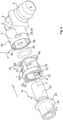
- a connector 1 has a housing 2 which has a sleeve portion 3 at its end. At its other end, the housing 2 has a plug-in section 4 z. B. for attaching a fluid line or a line connector. However, this plug-in section 4 can also be designed as a receiving section for plugging in a fluid line. Alternatively, the housing 2 can also be connected to a unit at the other end.
- the connector 1 can be used as an angle connector, as in 1 shown, be trained. Alternatively, however, the connector 1 may not be angled between the socket section 3 and the opposite end 4, or any angles between the parts 1 and 4 may be formed.
- a T-shaped or Y-shaped connector is also possible.
- the housing 2 has a through channel 5 .
- the through-channel 5 has a channel section 6 with an enlarged diameter.
- An adapter sleeve 7 is inserted into the socket section 3 with the channel section 6 of the housing 2 which is enlarged in diameter.
- This adapter sleeve 7 has a through opening 8 .
- the adapter sleeve 7 has a Through-opening 8 comprehensive sleeve wall 9.
- latching means are formed in the sleeve wall. These latching means preferably consist of two latching arms 10 which are radially elastic with respect to a longitudinal center axis XX of the adapter sleeve 7 and which are arranged offset from one another by 180°.
- latching arms 10 run parallel to the longitudinal center axis XX and are separated from the sleeve wall 9 by slit-shaped cutouts 11 on their longitudinal sides.
- the locking arms 10 are connected to the sleeve wall 9 .
- the latching arms 10 preferably have a smaller thickness than the wall thickness of the sleeve wall 9, so that between the outer circumference of the sleeve wall 9 and the latching arms 10 there is a stepped surface 9a running in the direction of the longitudinal central axis XX.
- annular step 9b is formed by reducing the diameter.
- guide grooves 9c extend on the circumference of the adapter sleeve 7 parallel to the longitudinal center axis XX, the groove base of which lies on the same radius around the longitudinal center axis XX as the circumference of the annular step 9b.
- the guide grooves 9c each have an insertion opening 9d which widens in a funnel shape in the insertion direction Z.
- the guide grooves 9c are used to guide guide ribs 9e formed on the inner wall of the channel section 6 when the adapter sleeve 7 is inserted into the channel section 6, the adapter sleeve 7 being aligned in such a way that the guide ribs 9e are inserted into the guide grooves 9c. This results in the correct positioning of the adapter sleeve 7 in the channel section 6.
- the latching arms 10 have, for example, at their free ends, latching cams 12 which are aligned radially in the direction of the longitudinal center axis XX. These locking cams 12 snap into place when the adapter sleeve 7 is inserted into the through-opening 8 a locking groove 13 of a mating connector 14 a. These latching cams 12 lie outside of the sleeve section 3 when the adapter sleeve 7 is in the inserted state
- the adapter sleeve 7 on the periphery of its through-opening 8, d. H. in the opening area at the rear, seen in the direction of insertion Z, has an annular collar 15 .
- This ring collar 15 extends radially outwards relative to the sleeve wall 9, so that its outer diameter is larger than the outer diameter of the sleeve wall 9 and expediently the same size as the outer diameter of the sleeve section 3.
- the ring collar 15 forms a kind of insertion limit for the adapter sleeve 7, the Ring collar 15 is located outside of the socket section 3 when the adapter sleeve 7 is in the inserted state.
- Web-like actuating extensions 16 that protrude radially outward with respect to the longitudinal center axis XX are formed on the locking arms 10 in particular on their free ends. These actuating projections 16 run through cutouts 17 running radially, specifically in relation to the central longitudinal axis XX, so that the annular collar 15 is interrupted by these cutouts 17 . At their free ends, the actuating projections 16 have projections 18 which are angled counter to the insertion direction Z and run parallel to the longitudinal center axis XX. These extensions 18 expediently run flush with the outer circumference of the annular collar 15, so that the radial spacing of the angled extensions 18 on their outer surface is equal to the outer diameter of the annular collar 15.
- open-edged guide grooves 19 with a U-shaped cross-section are formed in the annular collar 15 tangentially to the through-opening 8 of the adapter sleeve 7 in the radial direction outwards.
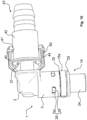
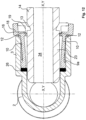
- the extensions 18 and the guide grooves 19 form a through opening for a release tool 20.
- This release tool 20 has z. B. a fork-shaped end portion 21 with two diametrically opposite forks 22.
- the distance between the forks 22 corresponds to the radial distance of the guide grooves 19 in the region of their bottom portions.
- the width of the forks 22 is less than / equal to the width of Guide grooves 19.
- the fork tines 22 have a height at their free ends that is smaller than the radial distance between the angled extensions 18 and the bottom section of the guide grooves 19. From their free end, the height of the fork tines 22 increases steadily to a height gauge.
- This height gauge is such that by inserting the fork prongs 22 perpendicularly to the longitudinal center axis XX into the insertion openings formed by the extensions 18 and the guide grooves 19, the latching arms 10 are elastically bent radially outwards in such a way that the radial distance between their latching cams 12 is greater than the outer diameter of a plug shank 23 of mating connector 14.
- plug shank 23 is in the inserted state of mating connector 14 within adapter sleeve 7, with latching cams 12 having latched into latching groove 13 of mating connector 14, by inserting release tool 20 into guide grooves 19 the locking position of the locking cams 12 is canceled and the plug shank 23 is pulled out of the adapter sleeve 7 .
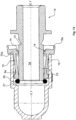
- the mating connector 14 has the plug shank 23 which has a circular cross section perpendicular to its central axis YY.
- the outer diameter of the plug shank 23 is greater than a radial distance between the locking cams 12, so that the locking arms 10 are bent radially outwards when the plug shank 23 is inserted.
- the plug shank 23 At its front end in the plug-in direction Z, the plug shank 23 has the locking groove 13 running circumferentially.
- the latching groove 13 has a contact surface at the front in the insertion direction Z, running perpendicular to the center axis YY, which interacts with a contact surface of the latching cam 12, also running perpendicular to the longitudinal center axis XX, in such a way that there is a form fit in the axial direction in the latched state, so that an independent Solving the plug pin or the plug shank 23 can not be done under tensile stress.
- a connection section 24 for connecting a fluid line or a unit is provided on the end of the mating connector 14 opposite the plug shank 23 . Between An annular collar 25, which can serve as a stop, is expediently formed onto the connection section 24 and the locking groove 13 of the mating connector 14.
- the length of the plug shank 23 is such that when it is plugged into the adapter sleeve 7 , its free end protrudes from the adapter sleeve 7 and extends into the through-channel 5 of the housing 2 .
- a peripheral seal 26 is arranged in front of the adapter sleeve 7 in the insertion direction Z within the socket section 3 .
- This peripheral seal 26 seals the peripheral gap between the plug shank 23 in its inserted state and the inner wall of the socket section 3 .
- the peripheral seal 26 is preferably designed as an O-ring and is enclosed within the socket section 3 between an inner annular shoulder 27 of the socket section 3 at the transition of the socket section 3 and an end face of the adapter sleeve 7 . Due to this configuration according to the invention, the formation of a receiving groove for the peripheral seal 26 is omitted, so that the formation of undercuts is not necessary in terms of production.
- peripheral seal 26 is arranged in a protected manner inside the socket section 3 when the adapter sleeve 7 is in the installed state.
- the inner diameter of the passage channel 5 of the housing 2 and the inner diameter of the passage opening 8 of the adapter sleeve 7 are adapted to the outer diameter of the plug shank 23 of the mating connector 14 .
- the inner diameter of the through-channel 5 and the through-opening 8 are expediently of the same size.
- the annular step 9b of the adapter sleeve 7 has a circumferential contact surface 27a running radially to the longitudinal center axis XX.
- the channel section 6 in particular has an annular stop surface 27b designed to increase the diameter, which is arranged in such a way that the peripheral seal 26 runs between the annular shoulder 27 and the stop surface 27b.
- the adapter sleeve 7 is positively fixed within the sleeve section 3 by means of form-fitting elements 28 in the axial and preferably also the circumferential direction.
- These positive-locking elements 28 preferably consist of radially elastically deformable locking tongues 29, which are formed outwards on the circumference of the adapter sleeve 7 between the locking arms 10 and are directed counter to the insertion direction Z of the adapter sleeve 7.
- the latching tongues 29 expediently run obliquely outwards at an acute angle to the longitudinal center axis XX in the sense of an increase in diameter.
- the latching tongues 29 correspond to recesses 30 in the peripheral wall of the socket section 3.
- the latching tongues 29 latch into the recesses 30 in a form-fitting manner.
- the recesses 30 are advantageously designed as openings in the wall of the socket section 3 .
- the latching tongues 29 are in particular dimensioned such that their free ends are in the latched state do not protrude from the openings.
- the latching tongues 29 have end surfaces running perpendicular to the longitudinal center axis XX of the adapter sleeve 7, and the recesses 30 have contact surfaces opposite the end surfaces of the latching tongues 29, which also run perpendicular to the longitudinal center axis XX.
- This design of the opposite surfaces requires a form fit in the axial direction when engaged.
- the snap-in tongues 29 and the recesses 30 are expediently adapted to one another in such a way that the adapter sleeve 7 cannot be twisted in the snapped-in state.
- FIGS Figures 1 to 4 Another embodiment of a connector 1 is shown, with the same parts and/or parts with the same function as in FIGS Figures 1 to 4 of the connector 1 shown therein are identified by the same reference numerals.
- the difference between the connector of the Figures 1 to 4 and the connector 1 according to the Figures 5 to 10 consists in the formation of the gorget.
- the annular collar 15a according to the Figures 5 to 10 is circumferentially separated from the adapter sleeve 7 by circumferential gap sections 32 between the locking arms 10 . In the area of the locking cams 12 of the locking arms 10, the annular collar 15a is connected to the locking arms 10 on the outside thereof.
- the annular collar 15a encloses the adapter sleeve 7 in the area of the free ends of the latching arms 10. According to the invention, it is advantageous if the annular collar 15a has two diametrically opposite deformation sections 33 in the middle between the latching arms 10. In the area of these deformation sections 33, the ring collar 15a can be deformed radially inwards by a force applied radially from the outside to the longitudinal center axis XX in such a way that the locking arms 10 are spread radially outwards in such a way that their locking cams 12 disengage from the locking groove 13 of the plug shank 23 of the inserted mating connector 14 come. This makes it possible for the mating connector 14 to be detached from the connector 1 by hand.
- the outer diameter of the annular collar 15a in the area of the locking cams 12 is in particular the same size as the outer diameter of the socket section 3.
- the deformation sections 33 are expediently formed by bulges of the annular collar 15a which are directed radially outwards in relation to the longitudinal center axis XX.
- the assembly of the adapter sleeve 7 in the illustrated embodiments takes place in such a way that the peripheral seal 26 is first introduced into the socket section 3 . Thereafter, the adapter sleeve 7 is inserted into the sleeve section 3 until their form-fitting elements 28, d. H. the latching tongues 29 into which the recesses 30 are latched.
- the mating connector 14 is plugged into the plug connector 1 according to the invention that has been completely assembled in this way, with the latching cams 12 of the latching arms 10 latching into the latching groove 13 of the mating connector 14 in the plugged-in state.
- connection section 24 of the mating connector 14 can be designed as a connection sleeve for inserting or screwing in a fluid connection or another connector part, see FIG figures 1 and 5 .
- connection section 24 can also be designed as a connection pin for attaching a fluid line, see for example 9 .
- a fluid channel 34 runs through the mating connector 14 and expediently has a channel inner diameter which corresponds to the inner diameter of the through-channel 5 of the housing 2 .
- the mating connector 14 has a latching groove 35 which has such an axial length that an axial displacement of the plug shank 23 in and against the insertion direction Z can take place when the mating connector 14 is in the inserted state.
- the length of the plug shank 23 between the locking groove 35 and its free end is dimensioned in such a way that in every position of the plug shank 23 in the adapter sleeve 7 there is a circumferential seal by means of the circumferential seal 26 arranged in the socket section 3 is guaranteed.
- the plug shank 23 is lengthened by the length of the latching groove 35, measured from its rear contact surface viewed in the insertion direction Z, ie the contact surface adjacent to the free end.
- This configuration means that a tolerance compensation in the plug connector 1 is possible, with a compensation dimension of 5 mm being expedient, for example.
- FIG. 12 is a connector 1 according to Figures 1 to 4 shown in an advantageous embodiment, wherein the mating connector 14 is not fully inserted into the connector 1, so that the locking cams 12 are not yet engaged in the locking groove 13.
- the plug shank 23 of the mating connector 14 has spread the spring arms 10 radially outwards in relation to the longitudinal center axis XX or YY, so that the angled extensions 18 protrude in the radial direction relative to the circumference of the socket section 3 .
- FIG. 13 is a corresponding insertion situation as in 12 for a connector 1 according to Figures 5 to 8 shown in a preferred embodiment.
- the annular collar 15a protrudes radially outwards with its sections connected to the locking arms 10 when the mating connector 15 is not yet fully inserted, so that this in turn provides a visual check as to whether the locking position has been reached or not. Because in the latching position, the outer circumference of the ring collar 15a is flush with the outer circumference of the sleeve section 3 .
- the plug-in section 4 of the connector 1 opposite the sleeve section 3 can be used as a sleeve for plugging in or screwing in a line connection or, for example, as a plug pin, see FIG 1 , be educated.
- the present invention also relates to a connector 1 in which the plug-in section 4 opposite the sleeve section 3 is designed as a connecting pin 37, see FIG 11 .
- This connecting pin 37 has a circular cross-section with respect to its longitudinal center axis Y 1 -Y 1 and has an inner fluid channel 38.
- This fluid channel 38 is in a connector 1 according to FIG Figures 1 to 11 -as well as in the figures 12 and 13 is shown - in the through channel 5 of the housing 2 over.
- the connecting pin 37 has a peripheral seal 39 arranged in a peripheral groove, in particular an O-ring seal.
- a plurality of latching webs 40 Arranged on the area opposite the free end of the connecting pin 37 are a plurality of latching webs 40 which extend in the direction of the free end and run parallel to the longitudinal center axis Y 1 -Y 1 , which are distributed at equal intervals around the circumference of the connecting pin 37 .
- the latching webs 40 At their free ends, the latching webs 40 have latching projections 41 directed radially inward with respect to the longitudinal center axis Y 1 -Y 1 .
- Between the locking bars 40 and the connecting pin 37 is formed a guide gap.
- a connecting sleeve 42 is pushed onto the connecting pin 37 in the guide gap formed between the latching webs 40 and the connecting pin 37 and is part of a connecting connector 43 for a fluid connection, for example a fluid line.
- This connecting sleeve 42 has an inner through bore, the inside diameter of which is adapted to the outside diameter of the connecting pin 37 , so that there is a peripheral gap that is sealed by the peripheral seal 39 .
- the peripheral seal 39 fixes the connecting sleeve 42 on the connecting pin 37 due to its deformation stress.
- the connecting sleeve 42 has, on its outer circumference, a ring shoulder 44 that protrudes radially outwards in relation to the longitudinal center axis Y 1 -Y 1 .
- This annular shoulder 44 and the latching shoulders 41 have corresponding inclined ramp surfaces 50a, 50b, so that when the connecting sleeve 42 is pushed on, the latching webs 40 are spread radially outwards.
- the latching projections 41 and the annular projection 44 are dimensioned relative to one another in such a way that the latching projections 41 represent an axial stop for the annular projection 44 .
- both parts have mutually facing stop surfaces 50a, 50b running perpendicularly to the longitudinal center axis Y 1 -Y 1 .
- This inventive design of the connecting pin 37 and the connecting sleeve 42 allows an axial relative displacement of these parts to each other in the connected state.
- the axial displacement path is determined by the length of the latching webs 40 up to the latching projections 41 .
- a connection pin or a connection sleeve for the attachment of a fluid connection can be formed on the end of the connection connector 36 opposite the connection sleeve 42 .
- An annular depth stop 45 for the connecting pin 37 can be formed inside the connecting connector 36 .
- the invention relates to a plug-in coupling from a connector with the mating connector according to 1 , 9 or 5 , 9 .
- the adapter sleeve 7 has a sleeve wall 9 that encompasses the through-opening 8.
- locking means are formed in the sleeve wall 9.
- These latching means consist of two latching arms 10 which are radially elastic with respect to a longitudinal center axis X-X of the adapter sleeve 7 and are arranged offset from one another by 180°. These latching arms 10 run parallel to the longitudinal center axis X-X and are separated from the sleeve wall 9 by slot-shaped cutouts 11 on their longitudinal sides.
- the latching arms 10 are connected to the sleeve wall 9 at their front end of the adapter sleeve in the insertion direction Z.
- the latching arms 10 have a smaller thickness than the wall thickness of the sleeve wall 9, so that between the outer circumference of the sleeve wall 9 and the latching arm 10 there is a stepped surface 9a running in the direction of the longitudinal center axis X-X.
- the latching arms 10 have at their free ends radially aligned first latching cams 12 in the direction of the longitudinal center axis XX.
- these first locking cams 12 snap into a locking groove 13 of an inserted mating connector or mating connector 14 that can be inserted, see FIG 15, 16 .
- These latching cams 12 are outside of the sleeve section 3 when the adapter sleeve 7 is in the inserted state in the sleeve section 3.
- the through-opening 8 has the same over its entire length Inner diameter, so that there is a continuous smooth, step-free inner wall. This merges in particular into an inclined insertion surface in the opening area of the through opening 8 in the opening area at the rear in the insertion direction Z.
- the adapter sleeve 7 has an annular collar 15 on the circumference of its through-opening 8, ie in the opening area at the rear, viewed in the direction of insertion Z.
- This annular collar 15 runs radially offset outwards with respect to the sleeve wall 9, so that its outer diameter and its inner diameter are in particular larger than the outer diameter of the sleeve wall 9.
- the outer diameter of the annular collar 15 is expediently the same size as that of the sleeve section 3, as in 17
- an annular step 9b is formed at the front end of the adapter sleeve 7 in the insertion direction Z by reducing the diameter.
- guide grooves 9c extend on the circumference of the adapter sleeve 7 parallel to the longitudinal center axis XX, the groove base of which lies on the same radius around the longitudinal center axis XX as the circumference of the annular step 9b.
- the guide grooves 9c each have an insertion opening 9d which widens in a funnel shape in the insertion direction Z.
- the guide grooves 9c are used to guide guide ribs 9e formed on the inner wall of the channel section 6 when the adapter sleeve 7 is inserted into the channel section 6, the adapter sleeve 7 being aligned in such a way that the guide ribs 9e are inserted into the guide grooves 9c. This results in the correct positioning of the adapter sleeve 7 in the channel section 6.
- the adapter sleeve 7 is positively fixed within the sleeve section 3 by means of form-fitting elements in the axial and preferably also the circumferential direction.
- These positive-locking elements consist of radially elastic latching means formed on the circumference of the adapter sleeve 7 between the latching arms 9, 10.
- This locking means are in particular formed of two radially elastically bendable arms 29a running axially parallel to the longitudinal center axis XX. These arms 29a are offset from each other by 90° to the latching arms 10 .
- the arms 29a are separated from the wall of the adapter sleeve 7 by a U-shaped slot 29b and are integrally connected to the wall of the adapter sleeve 7 with their end pointing counter to the insertion direction Z, see FIG 17 .
- the arms 29a At their free ends, the arms 29a have second latching cams 29c, which project radially outwards and have an inclined surface 29d pointing in the direction of insertion Z, and a latching surface 29e running perpendicular to the longitudinal center axis XX, which is connected to the inclined surface 29d at its outer free end includes an acute angle.
- a circumferential circle on which the free ends of the second locking cams 29c lie has a diameter which is larger than the inside diameter of the channel section 6 of the socket section 3 and smaller than the outside diameter of the channel section 6 . It is expedient if a stiffening extension 29f is formed behind the respective first latching cam 10 as viewed in the insertion direction Z.
- the thickness of the arms 29 is preferably smaller than the thickness of the wall of the adapter sleeve 7. The spring elasticity of the arms 29a can be adjusted via the length and the thickness of the arms 29a.
- the second locking cams 29c correspond to recesses 30 in the peripheral wall of the sleeve section 3 in such a way that when the adapter sleeve 7 is inserted into the sleeve section 3, the second locking cams 29c engage in the recesses 30 in a form-fitting manner.
- the recesses 30 are advantageously designed as openings in the wall of the socket section 3 .
- the second latching cams 29c are in particular dimensioned in such a way that their free ends do not protrude from the openings 30 in the latched state.
- the adapter sleeve 7 can be inserted in positions rotated by 90° relative to one another. It is also within the scope of the invention if the openings 30 as inner Depressions are formed so that the peripheral wall of the sleeve portion 3 is closed.
- the second locking cams 29c engage with their locking surfaces 29e running perpendicular to the longitudinal center axis X-X, and the recesses 30 have contact surfaces opposite the locking surfaces 29e, which also run perpendicular to the longitudinal center axis X-X. This design of the opposite surfaces requires a form fit in the axial direction when engaged.
- the second latching cams 29c and the recesses 30 are expediently adapted to one another in such a way that the adapter sleeve 7 cannot be rotated in the latched state.
- actuating extensions 16 are formed which protrude radially outwards in relation to the longitudinal center axis XX. These actuating projections 16 run through cutouts 17 running radially, specifically in relation to the central longitudinal axis XX, so that the annular collar 15 is interrupted by these cutouts 17 . At their free ends, the actuating projections 16 have projections 18 which are angled counter to the insertion direction Z and run parallel to the longitudinal center axis XX.
- a fork-shaped end portion 21 with two diametrically opposite forks 22 The distance between the forks 22 corresponds to the radial distance of the guide grooves 19 in the region of their bottom portions.
- the width of the forks 22 is less than/equal to the width of the guide grooves 19.
- the fork tines 22 At their free ends, the fork tines 22 have a height that is less than the radial distance between the angled extensions 18 and the bottom section of the guide grooves 19. From their free end, the height of the fork tines 22 increases steadily towards a height gauge.
- This height gauge is such that by inserting the fork prongs 22 perpendicularly to the longitudinal center axis XX into the insertion openings formed by the extensions 18 and the guide grooves 19, the latching arms 10 are elastically bent radially outwards in such a way that the radial distance between their latching cams 12 is greater than the outer diameter of a plug shank 23 of mating connector 14. If plug shank 23 is in the inserted state of mating connector 14 within adapter sleeve 7, with latching cams 12 having latched into latching groove 13 of mating connector 14, by inserting release tool 20 into guide grooves 19 the locking position of the locking cams 12 is canceled and the plug shank 23 is pulled out of the adapter sleeve 7 .
- the release tool 20 advantageously has between the forks 22 a guide bar 22a running parallel to the forks 22, which is guided in a recess 22b in the annular collar 15 when the release tool 20 is in the inserted state, so that the release tool 20 is prevented from tilting.
- Two opposing recesses 22b are preferably provided in the annular collar.
- a release safeguard 60 is arranged on the outer circumference of the sleeve section 3 so as to be displaceable in the longitudinal direction of the longitudinal center axis XX.
- This anti-release device 60 is slidably mounted between two positions, in particular locking positions.
- the first position is an assembly position in which the mating connector 40 can be inserted or is inserted into the connector according to the invention, specifically into the adapter sleeve 7, see FIG 16 .
- the second position is a position in which the anti-release device 60 is displaced in the direction of the ring collar 15 in such a way that the anti-release device 60 prevents the latching arms 10 from spreading radially.
- the anti-release device 60 consists of a sleeve 61 that positively encloses the sleeve section 3.
- This sleeve 61 is slidably mounted on the sleeve section 3, specifically between the two positions described above. In the first position the sleeve 61 is completely on the sleeve portion 3, see 16 , so that the annular collar 15 is freely accessible and a spreading of the locking arms 10 by means of the release tool 20 is possible, so that the locking arms 10 can be spread radially when the mating connector 14 is inserted. In this position, the sleeve 61 engages z. B.
- the latching arms 10 can no longer be spread apart, so that the plug-in connection according to the invention can be unintentionally released when the mating plug-in connector 14 is plugged in is prevented.
- the sleeve 61 engages with its detent tongues 63 in the peripheral wall of the sleeve section 3 in a force-fitting manner, ie releasably, in the recesses 65a present there, which can coincide with the recesses 30 .
- the sleeve 61 has guide grooves 68 in its sleeve wall for receiving the longitudinal ribs 67 .
Landscapes
- Engineering & Computer Science (AREA)
- General Engineering & Computer Science (AREA)
- Mechanical Engineering (AREA)
- Quick-Acting Or Multi-Walled Pipe Joints (AREA)
Claims (25)
- Connecteur enfichable (1) servant à la connexion d'au moins une conduite de fluide à une autre conduite de fluide ou à un raccordement d'unité, comportant un boîtier (2) doté d'un canal de passage (5), une extrémité du boîtier (2) étant réalisée sous forme de partie de manchon (3) servant à l'enfichage d'un connecteur enfichable conjugué (14) et présentant des moyens d'encliquetage (10, 12) pour la fixation amovible du connecteur enfichable conjugué (14), les moyens d'encliquetage (10, 12) faisant partie d'une douille d'adaptation (7) pouvant être enfichée dans la partie de manchon (3), laquelle douille d'adaptation est retenue dans la partie de manchon (3) au moyen d'éléments d'engagement par complémentarité de formes (28), et présentant une ouverture de passage (8) pour une tige de connecteur (23) du connecteur enfichable conjugué (14), et les moyens d'encliquetage étant formés à partir d'au moins deux bras d'encliquetage (10) radialement élastiques par rapport à un axe médian longitudinal (X-X) de la douille d'adaptation (7), les bras d'encliquetage (10) étant moulés sur l'extrémité de la douille d'adaptation (7) située à l'intérieur de la partie de manchon (3) dans l'état enfiché et les bras d'encliquetage (10) présentant à leur extrémité libre des premières cames d'encliquetage (12) s'étendant radialement en direction de l'axe médian longitudinal (X-X), les éléments d'engagement par complémentarité de formes (28) étant formés à partir de bras (29a) déformables de manière radialement élastique et s'étendant respectivement parallèlement à l'axe médian longitudinal (X-X), lesquels bras sont diamétralement opposés et sont décalés de 90° par rapport aux bras d'encliquetage (10) et présentent à leurs extrémités libres orientées dans le sens d'enfichage (Z) des deuxièmes cames d'encliquetage (29c) faisant saillie radialement vers l'extérieur,
caractérisé en ce que les bras d'encliquetage (10) s'étendent parallèlement à l'axe médian longitudinal (X-X) et sont formés à la périphérie de la douille d'adaptation (7) par des découpes (11) en forme de fentes dans sa paroi de douille, les bras (29a) étant séparés de la paroi de la douille d'adaptation (7) par une fente (29b) en forme de U et étant connectés d'une seule pièce à la paroi de la douille d'adaptation (7) par leur extrémité orientée en sens inverse du sens d'enfichage (Z) . - Connecteur enfichable (1) selon la revendication 1, caractérisé en ce que les deuxièmes cames d'encliquetage (29c) des bras (29a) présentent respectivement une surface inclinée (29d) orientée dans le sens d'enfichage (Z) et une surface d'encliquetage (29e) orientée en sens inverse du sens d'enfichage (Z) et s'étendant perpendiculairement à l'axe médian longitudinal (X-X).
- Connecteur enfichable (1) selon la revendication 1 ou 2,
caractérisé en ce que les deuxièmes cames d'encliquetage (29c) des bras (29a) se situent par leurs extrémités libres sur un cercle périphérique dont le diamètre est inférieur au diamètre extérieur de la partie de manchon (3) et supérieur au diamètre intérieur de la partie de canal (6) de la partie de manchon (3). - Connecteur enfichable (1) selon l'une des revendications 1 à 3,
caractérisé en ce que l'épaisseur des bras d'encliquetage (10) est inférieure à l'épaisseur de paroi de la douille d'adaptation (7), de sorte qu'une surface étagée (9a) s'étendant radialement en direction de l'axe médian longitudinal (X-X) soit formée entre la périphérie extérieure de la paroi de la douille d'adaptation (7) et les bras d'encliquetage (10). - Connecteur enfichable (1) selon la revendication 4, caractérisé en ce que la hauteur radiale de la surface étagée (9a) et la longueur des bras d'encliquetage (10) à l'intérieur de la partie de manchon (3) sont dimensionnées de telle sorte qu'un débattement, orienté radialement vers l'extérieur, des premières cames d'encliquetage (12) soit défini de telle sorte que la distance radiale des premières cames d'encliquetage (12) écartées radialement vers l'extérieur par rapport à l'axe médian longitudinal (X-X) soit au moins égale au diamètre intérieur de l'ouverture de passage (8) de la douille d'adaptation (7) et au moins égale au diamètre extérieur de la tige de connecteur (14a) du connecteur enfichable conjugué (14).
- Connecteur enfichable (1) selon l'une des revendications 1 à 5,
caractérisé en ce que les éléments d'engagement par complémentarité de formes (28) sont fixés par complémentarité de formes dans des évidements (30) de la paroi périphérique de la partie de manchon (3) dans la direction périphérique de la douille d'adaptation (7), en particulier quatre évidements (30) décalés les uns par rapport aux autres de 90° étant formés. - Connecteur enfichable (1) selon l'une des revendications 1 à 6,
caractérisé en ce que la douille d'adaptation (7) présente une collerette annulaire (15) s'étendant à la périphérie de son ouverture de passage (8) au niveau de son bord d'ouverture arrière vu dans le sens d'enfichage (Z), laquelle collerette annulaire est disposée à l'extérieur de la partie de manchon (3) dans l'état enfiché de la douille d'adaptation (7), et les premières cames d'encliquetage (12) s'étendent également à l'extérieur de la partie de manchon (3). - Connecteur enfichable (1) selon la revendication 7, caractérisé en ce que la collerette annulaire (15) est circulaire sur sa périphérie et son diamètre extérieur est inférieur ou égal à un diamètre extérieur d'un contour périphérique circulaire de la partie de manchon (3) respectivement à un diamètre extérieur de la partie de manchon (3).
- Connecteur enfichable (1) selon l'une des revendications 1 à 8,
caractérisé en ce que des bras d'encliquetage (10) décalés de 180° l'un par rapport à l'autre sont formés et des saillies d'actionnement (16) faisant saillie radialement vers l'extérieur par rapport à l'axe médian longitudinal (X-X) sont formées aux extrémités libres des bras d'encliquetage (10). - Connecteur enfichable (1) selon la revendication 9, caractérisé en ce que, dans la région des saillies d'actionnement (16), des rainures de guidage (19) respectivement des orifices (19) à bord ouvert s'étendant tangentiellement à l'ouverture de passage (8) de la douille d'adaptation (7) sont formés de manière sécante sur la collerette annulaire (15), la collerette annulaire (15) étant interrompue par les saillies d'actionnement (16), et les saillies d'actionnement (16) présentant respectivement une saillie (18) s'étendant parallèlement à l'axe médian longitudinal (X-X) à l'extérieur de la rainure de guidage (19) respective, inclinée en sens inverse du sens d'enfichage (Z), de sorte qu'une ouverture d'enfichage appropriée à l'introduction d'un outil de desserrage (20) soit formée entre les saillies (18) et les rainures de guidage (19).
- Connecteur enfichable (1) selon l'une des revendications 7 à 10,
caractérisé en ce que la collerette annulaire (15a) est séparée de la douille d'adaptation (7) par des parties d'interstice périphériques entre les bras d'encliquetage (10) et entoure les bras d'encliquetage (10) dans la région des premières cames d'encliquetage (12) sur leur côté extérieur et est connectée à ceux-ci dans cette région, et la collerette annulaire (15a) présente des parties de déformation (33) centralement entre les bras d'encliquetage (10), lesquelles parties de déformation sont déformables sous l'effet d'une force orientée radialement par rapport à l'axe médian longitudinal (X-X), de telle sorte qu'un écartement, orienté radialement vers l'extérieur, des bras d'encliquetage (10) soit produit de telle sorte que les premières cames d'encliquetage (12) adoptent leur position de desserrement. - Connecteur enfichable (1) selon la revendication 10, caractérisé en ce que la distance radiale des saillies (18) inclinées des saillies d'actionnement (16) sur leurs surfaces extérieures est égale à un diamètre extérieur de la collerette annulaire (15).
- Connecteur enfichable (1) selon la revendication 12, caractérisé en ce qu'un diamètre extérieur de la collerette annulaire (15a) dans la région des premières cames d'encliquetage (12) est égal au diamètre extérieur de la partie de manchon (3).
- Connecteur enfichable (1) selon l'une des revendications 1 à 13,
caractérisé en ce qu'un joint périphérique (26) est disposé avant la douille d'adaptation (7) dans le sens d'enfichage (Z) dans l'ouverture de passage (8) de la partie de manchon (3), pour réaliser l'étanchéité d'un interstice périphérique entre une paroi intérieure de la partie de manchon (3) et la tige de connecteur (23) d'un connecteur enfichable conjugué (14). - Connecteur enfichable (1) selon l'une des revendications 1 à 14,
caractérisé en ce qu'une sécurité contre le desserrage (60) est disposée de manière mobile dans la direction longitudinale (X-X) entre deux positions d'encliquetage à la périphérie extérieure de la partie de manchon (3), la sécurité contre le desserrage (60) empêchant un écartement des bras d'encliquetage (10) dans sa deuxième position d'encliquetage déplacée vers la collerette annulaire (15) et, dans son autre position d'encliquetage, les bras d'encliquetage (10) pouvant être écartés. - Connecteur enfichable (1) selon la revendication 15, caractérisé en ce que la sécurité contre le desserrage (60) est constituée d'une douille (61) entourant la partie de manchon (3), laquelle douille présente des languettes d'encliquetage (63) au niveau de son bord périphérique (62) orienté dans le sens d'enfichage (Z), lesquelles languettes s'encliquettent dans la position d'encliquetage respective dans des évidement (65) de la paroi périphérique de la partie de manchon (3).
- Connecteur enfichable (1) selon la revendication 16, caractérisé en ce que la douille (61) entoure la collerette annulaire (15) ainsi que les saillies (18) dans sa position d'encliquetage bloquant l'écartement des bras d'encliquetage (10).
- Connecteur enfichable (1) selon l'une des revendications 14 à 17, caractérisé en ce qu'un épaulement annulaire (27) servant à l'appui du joint périphérique (26) servant à réaliser l'étanchéité des interstices périphériques est formé dans la partie de manchon (3) à la transition d'une partie de canal (6), de diamètre élargi, de la partie de manchon (3) vers le canal de passage (5), et le joint périphérique (26) est encastré entre l'épaulement annulaire (27) et une surface d'extrémité frontale de la douille d'adaptation (7).
- Connecteur enfichable (1) selon l'une des revendications 1 à 18,
caractérisé en ce que le boîtier (2) présente, à son extrémité opposée à la partie de manchon (3), un tenon de raccordement (37) qui possède à son extrémité libre un joint périphérique (39) et, au niveau de la région du tenon de raccordement (37) opposée à l'extrémité libre, sont disposées plusieurs nervures d'encliquetage (40) s'étendant en direction de l'extrémité libre, parallèlement à l'axe médian longitudinal (Y-Y), lesquelles nervures possèdent à leurs extrémités des rallonges d'encliquetage (41) orientées vers l'intérieur radialement par rapport à l'axe médian longitudinal (Y-Y) . - Connecteur enfichable (1) selon la revendication 19, caractérisé en ce qu'un interstice de guidage est formé entre les nervures d'encliquetage (40) et le tenon de raccordement (37), interstice de guidage dans lequel une douille de raccordement (42) peut être insérée, laquelle possède un alésage de passage pour la réception du tenon de raccordement (37), et présente un insert annulaire faisant saillie radialement vers l'extérieur par rapport à l'axe médian longitudinal (Y-Y), lequel insert annulaire, dans l'état enfilé de la douille de raccordement (42), peut être déplacé à l'intérieur de l'interstice de guidage entre les rallonges d'encliquetage (41) et l'extrémité opposée des nervures d'encliquetage (40).
- Connecteur enfichable (1) selon l'une des revendications 1 à 20,
caractérisé en ce qu'un étage annulaire (9b) est formé par une réduction de diamètre de la douille d'adaptation (7) à l'extrémité avant de la douille d'adaptation (7) dans le sens d'enfichage (Z), et des rainures de guidage (9c) s'étendant à partir de cet étage annulaire (9b) à la périphérie de la douille d'adaptation (7) parallèlement à l'axe médian longitudinal (X-X) sont formées, dont le fond de rainure se situe sur le même rayon que la périphérie de l'étage annulaire (9b), les rainures de guidage (9c) servant à la réception et au guidage de nervures de guidage (9e) dans l'état enfiché de la douille d'adaptation (7), lesquelles nervures de guidage sont formées sur l'intérieur de la partie de canal (6) sur sa paroi intérieure. - Connecteur enfichable (1) selon la revendication 21, caractérisé en ce que l'étage annulaire (9b) de la douille d'adaptation (7) présente une surface d'appui (27a) périphérique s'étendant radialement par rapport à l'axe médian longitudinal (X-X), et la partie (6a) de la partie de canal (6) possède une surface de butée annulaire (27b) formée au sens d'une augmentation de diamètre, et dans l'état enfiché de la douille d'adaptation (7), celle-ci s'appuyant par sa surface d'appui (27a) contre la surface de butée (27b).
- Raccord enfichable, constitué d'un connecteur enfichable (1) selon l'une des revendications 1 à 22 ainsi que d'un connecteur enfichable conjugué (14) destiné à être enfiché dans le connecteur enfichable (1) avec une tige de connecteur (23) et d'une rainure d'encliquetage (13) formée derrière la tige de connecteur (23) dans le sens d'enfichage (Z),
caractérisé en ce que la tige de connecteur (23) est dimensionnée de telle sorte que, dans l'état enfiché, son extrémité libre dépasse de la douille d'adaptation (7) et se termine dans le canal de passage (5) du boîtier (2) du connecteur enfichable (1) et que son diamètre extérieur soit supérieur à la distance radiale entre les premières cames d'encliquetage (12) dans l'état non écarté. - Raccord enfichable selon la revendication 23, caractérisé en ce que la rainure d'encliquetage (13) est disposée et formée de telle sorte que, dans l'état enfiché de la tige de connecteur (23), les bras de retenue (10) s'encliquètent par complémentarité de formes dans la rainure d'encliquetage (13) par leurs premières cames d'encliquetage (12).
- Raccord enfichable selon la revendication 23 ou 24, caractérisé en ce que la rainure d'encliquetage (13) présente une étendue axiale dans la direction du sens d'enfichage (Z) telle qu'un déplacement axial de la tige de connecteur (23) dans l'état enfiché dans la douille d'adaptation (7) sur un trajet de déplacement soit défini, et la longueur de la tige de connecteur (23) entre la rainure d'encliquetage (13) et son extrémité libre étant dimensionnée de telle sorte que la tige de connecteur (23) soit prolongée de la longueur du trajet de déplacement axial.
Applications Claiming Priority (3)
| Application Number | Priority Date | Filing Date | Title |
|---|---|---|---|
| DE102014107655.9A DE102014107655B4 (de) | 2014-05-30 | 2014-05-30 | Steckverbinder für Fluidleitungen mit innenliegender Adapterhülse |
| PCT/EP2015/057243 WO2015180875A1 (fr) | 2014-05-30 | 2015-04-01 | Raccord enfichable pour conduites de fluide, muni d'une douille d'adaptation intérieure |
| PCT/EP2015/062178 WO2015181396A2 (fr) | 2014-05-30 | 2015-06-01 | Raccord enfichable pour conduites de fluide, muni d'une douille d'adaptation intérieure |
Publications (2)
| Publication Number | Publication Date |
|---|---|
| EP3149383A2 EP3149383A2 (fr) | 2017-04-05 |
| EP3149383B1 true EP3149383B1 (fr) | 2023-08-02 |
Family
ID=53724284
Family Applications (2)
| Application Number | Title | Priority Date | Filing Date |
|---|---|---|---|
| EP15741903.7A Active EP3149384B1 (fr) | 2014-05-30 | 2015-04-01 | Raccord enfichable pour conduites de fluide, muni d'une douille d'adaptation intérieure |
| EP15726599.2A Active EP3149383B1 (fr) | 2014-05-30 | 2015-06-01 | Raccord enfichable pour conduites de fluide, muni d'une douille d'adaptation intérieure |
Family Applications Before (1)
| Application Number | Title | Priority Date | Filing Date |
|---|---|---|---|
| EP15741903.7A Active EP3149384B1 (fr) | 2014-05-30 | 2015-04-01 | Raccord enfichable pour conduites de fluide, muni d'une douille d'adaptation intérieure |
Country Status (5)
| Country | Link |
|---|---|
| US (2) | US10465827B2 (fr) |
| EP (2) | EP3149384B1 (fr) |
| CN (3) | CN106461139B (fr) |
| DE (1) | DE102014107655B4 (fr) |
| WO (2) | WO2015180875A1 (fr) |
Families Citing this family (43)
| Publication number | Priority date | Publication date | Assignee | Title |
|---|---|---|---|---|
| DE102014107655B4 (de) * | 2014-05-30 | 2024-07-11 | Voss Automotive Gmbh | Steckverbinder für Fluidleitungen mit innenliegender Adapterhülse |
| DE102016110717B3 (de) * | 2016-06-10 | 2017-08-03 | HARTING Electronics GmbH | Steckverbinder |
| US10006577B2 (en) | 2016-07-15 | 2018-06-26 | Miniature Precision Components, Inc. | Permanent quick connector and assembly therewith |
| CN109496254B (zh) * | 2016-07-29 | 2021-07-16 | 福士汽车配套部件责任有限公司 | 保持元件和具有该保持元件的连接器 |
| DE102016009168A1 (de) | 2016-07-29 | 2018-02-01 | Voss Automotive Gmbh | Anschlussverbinder |
| CN106337984B (zh) * | 2016-11-23 | 2017-11-10 | 黄松檀 | 一种应用于无人驾驶汽车的管路连接器中组合式锁紧扣件 |
| CN106337985B (zh) * | 2016-11-23 | 2017-12-05 | 黄松檀 | 一种应用于无人驾驶汽车的管路连接器 |
| KR102636742B1 (ko) * | 2016-12-27 | 2024-02-15 | 현대자동차주식회사 | 차량용 유압튜브 커넥터 |
| CN106943014B (zh) * | 2017-03-10 | 2019-03-19 | 张致睿 | 设可抬起的行走轮的饮水机 |
| DE102017004450A1 (de) * | 2017-05-09 | 2018-11-15 | Diehl Metering Gmbh | Anordnung zum Einbau in ein Fluidleitungsnetz |
| CN109404647A (zh) * | 2017-08-17 | 2019-03-01 | A.雷蒙德公司 | 可拆卸的快速连接装置 |
| US10865922B2 (en) * | 2017-10-05 | 2020-12-15 | Novares Us Engine Components, Inc. | Anti-tamper permanent quick connect coupling device |
| CN108253857B (zh) * | 2018-01-16 | 2024-01-19 | 西安物华巨能爆破器材有限责任公司 | 一种用于磁电雷管和传爆管之间的插接套 |
| JP2019148324A (ja) * | 2018-02-28 | 2019-09-05 | トヨタ自動車株式会社 | 継手構造 |
| DE102018212376A1 (de) | 2018-07-25 | 2020-01-30 | Contitech Mgw Gmbh | Fluidkupplung mit Toleranzausgleich zur flexiblen Verbindung zweier medienführender Elemente |
| CN109114321A (zh) * | 2018-10-23 | 2019-01-01 | 黄子颢 | 一种管道连接组件及管道 |
| FR3072154B1 (fr) * | 2018-11-12 | 2020-09-04 | Parker Hannifin Emea Sarl | Ensemble de raccordement de conduits de transport de fluide |
| DE102018219932A1 (de) | 2018-11-21 | 2020-05-28 | Fränkische Industrial Pipes GmbH & Co. KG | Kopplung |
| DE102018220521A1 (de) * | 2018-11-28 | 2020-05-28 | Fränkische Industrial Pipes GmbH & Co. KG | Fluidverbindung |
| CN110274112A (zh) * | 2019-07-25 | 2019-09-24 | 浙江万全机械制造有限公司 | 一种用于流体导管的直角插拔连接总成 |
| DE102020203797A1 (de) | 2020-03-24 | 2021-09-30 | Hansgrohe Se | Wandeinbau-Anschlussboxeinheit mit Verlängerungshülse |
| DE202020101638U1 (de) | 2020-03-24 | 2020-04-24 | Voss Automotive Gmbh | Steckverbinder mit Vormontagesicherung |
| DE102020108073A1 (de) | 2020-03-24 | 2021-09-30 | Voss Automotive Gmbh | Steckverbinder mit Vormontagesicherung |
| DE102020203792A1 (de) | 2020-03-24 | 2021-09-30 | Hansgrohe Se | Wandeinbau-Anschlussboxeinheit |
| DE102020203794A1 (de) | 2020-03-24 | 2021-09-30 | Hansgrohe Se | Wandeinbau-Anschlussboxeinheit mit Funktionsflächenkörper |
| DE102020203800A1 (de) | 2020-03-24 | 2021-09-30 | Hansgrohe Se | Sanitäre Wandeinbau-Anschlussboxeinheit mit elektrischer Leitungsdurchführung |
| DE102020110069A1 (de) | 2020-04-09 | 2021-10-14 | Sartorius Stedim Biotech Gmbh | Verbindungsklemme zur mechanischen Verbindung von zwei bioprozesstechnischen Systemkomponenten |
| US11738188B2 (en) * | 2020-06-08 | 2023-08-29 | Covidien Lp | Connection of intravascular interventional elements and elongate manipulation members |
| DE102020126814A1 (de) * | 2020-10-13 | 2022-04-14 | Voss Automotive Gmbh | Elastischer Steckverbinder |
| IL280146B2 (en) * | 2021-01-13 | 2024-01-01 | Rivulis Plastro Ltd | Drip irrigation lateral connector to feeder pipe |
| US12186837B2 (en) * | 2021-03-03 | 2025-01-07 | Alpha/Omega Energy Solutions, LLC | Female welding lead connector collar including safety flip cover |
| EP4060217B1 (fr) | 2021-03-18 | 2025-04-30 | Hanil Tube Corporation | Connecteur rapide avec dispositif de retenue et de vérification |
| DE102021108451A1 (de) | 2021-04-01 | 2022-10-06 | Voss Automotive Gmbh | Steckverbinder für Fluidleitungen mit innenliegender Adapterhülse |
| DE102021124681A1 (de) | 2021-09-23 | 2023-03-23 | Voss Automotive Gmbh | Steckverbinder mit Vormontagesicherung |
| CN113733161B (zh) * | 2021-09-30 | 2023-01-17 | 北京空间飞行器总体设计部 | 一种机械臂末端执行器快速接口装置 |
| EP4473237A1 (fr) | 2022-02-01 | 2024-12-11 | Voss Automotive GmbH | Raccord enfichable à protection de montage |
| DE102022104970A1 (de) | 2022-02-01 | 2023-08-03 | Voss Automotive Gmbh | Steckverbinder mit Montagesicherung |
| DE102022107490A1 (de) | 2022-03-30 | 2023-10-05 | Voss Automotive Gmbh | Modularer Steckverbinder |
| CN115289288A (zh) * | 2022-08-05 | 2022-11-04 | 深圳市欣普斯科技有限公司 | 液冷散热泵及其管接头连接结构 |
| DE102022212148A1 (de) * | 2022-11-15 | 2024-05-16 | Mahle International Gmbh | Crimp-Werkzeug und damit hergestellter Wärmeübertrager |
| CN223563712U (zh) * | 2024-11-08 | 2025-11-18 | 温州弗锐斯建材有限公司 | 接头组件 |
| US12435821B1 (en) * | 2025-05-15 | 2025-10-07 | Kangkang Tong | Quick-insertion connection structure for professional atomizer foam cannon |
| CN120350748B (zh) * | 2025-06-23 | 2025-08-29 | 中国十七冶集团有限公司 | 插入式自锁连接装置及在梁柱结构上的应用和安装方法 |
Family Cites Families (30)
| Publication number | Priority date | Publication date | Assignee | Title |
|---|---|---|---|---|
| US2485763A (en) * | 1946-07-16 | 1949-10-25 | Signal Oil & Gas Co | Tool joint |
| US3782840A (en) * | 1971-10-05 | 1974-01-01 | Sealectro Corp | Mechanical coupling |
| US5275448A (en) * | 1991-09-10 | 1994-01-04 | Huron Products Industries, Inc. | Quick connect tubing connector and method of assembly |
| DE4214105A1 (de) | 1992-04-29 | 1993-11-04 | Voss Armaturen | Steckverbinder fuer schlauch- oder rohrleitungen, insbesondere fuer kraftstoffleitungen von verbrennungsmotoren |
| FR2717883B1 (fr) * | 1994-03-04 | 1996-06-14 | Hutchinson | Dispositif de raccordement rapide et étanche pour conduites tubulaires. |
| DE69621292T2 (de) * | 1995-07-28 | 2002-12-19 | John Guest Ltd., West Drayton | Rohrverbindung |
| GB9724521D0 (en) * | 1997-11-20 | 1998-01-21 | Munster Simms Engineering Limi | Pipe connections |
| DE19822574C1 (de) * | 1998-05-20 | 1999-10-14 | Raymond A & Cie | Lösbare Schnellkupplung mit automatischer Montageanzeige |
| FR2780765B1 (fr) * | 1998-07-01 | 2000-09-29 | Caillau Ets | Embout de connexion rapide ayant une piece monobloc formant un organe de verrouillage et une bague de blocage du joint |
| DE10115399C1 (de) * | 2001-03-29 | 2002-06-06 | Raymond A & Cie | Lösbare Steckverbindung mit zusätzlichem Verriegelungselement |
| US6467816B1 (en) * | 2001-08-21 | 2002-10-22 | Huang-Fu Huang | Water pipe joint |
| EP1561990B1 (fr) * | 2004-02-05 | 2008-08-20 | TI Group Automotive Systems LLC | Connecteur rapide |
| DE102004053538A1 (de) * | 2004-11-05 | 2006-05-11 | Veritas Ag | Kupplungsvorrichtung zum Verbinden von Leitungen und Kraftfahrzeug mit einer derartigen Kupplungsvorrichtung |
| DE102005060135A1 (de) * | 2005-12-16 | 2007-07-05 | A. Raymond Et Cie | Kupplung |
| DE102006013899B3 (de) | 2006-03-25 | 2006-11-30 | Rasmussen Gmbh | Steckkupplung |
| DE102007009947B4 (de) * | 2007-03-01 | 2016-11-24 | Techpointe S.A. | Steckerelement |
| DE102007032324B4 (de) * | 2007-07-11 | 2012-10-31 | A. Raymond Et Cie | Fluidleitungskupplung |
| DE102008013565B4 (de) | 2008-03-11 | 2025-12-04 | A. Kayser Automotive Systems Gmbh | Einsteckkupplung |
| JP5306868B2 (ja) * | 2009-03-23 | 2013-10-02 | 株式会社ニフコ | パイプ連結用コネクタ |
| DE102010010522B4 (de) | 2010-03-05 | 2012-10-25 | Voss Automotive Gmbh | Steckverbinder für Medienleitungen |
| CN102782385B (zh) * | 2010-03-05 | 2014-08-27 | 福士汽车配套部件责任有限公司 | 用于介质导管的插拔连接器 |
| NL2007552C2 (en) * | 2011-10-07 | 2013-04-09 | Andries Valk | Coupling device, line path and line end section. |
| DE102011084988C5 (de) | 2011-10-21 | 2024-11-21 | Fränkische Industrial Pipes GmbH & Co. KG | Verbindungseinheit und eine derartige Verbindungseinheit umfassende Verbindungsanordnung |
| DE102011118099A1 (de) * | 2011-11-10 | 2013-05-16 | Illinois Tool Works Inc. | Vorrichtung zum Verbinden zweier Leitungsabschnitte |
| DE202012000597U1 (de) * | 2012-01-13 | 2013-04-22 | Neoperl Gmbh | Lösbare Steckverbindung |
| DE102012106925A1 (de) * | 2012-07-30 | 2014-06-12 | Contitech Schlauch Gmbh | Schnellverbindungsanordnung zur lösbaren Verbindung einer Medienleitung mit einem Stutzen |
| DE102012107463A1 (de) * | 2012-08-15 | 2014-06-12 | Contitech Schlauch Gmbh | Schnellverbindungsanordnung zur lösbaren Verbindung einer Medienleitung mit einem Stutzen |
| EP2728236B1 (fr) * | 2012-11-05 | 2017-04-19 | TI Automotive (Fuldabrück) GmbH | Accouplement rapide |
| EP3399220B1 (fr) * | 2013-01-15 | 2019-05-15 | TI Automotive (Fuldabrück) GmbH | Raccord rapide |
| DE102014107655B4 (de) * | 2014-05-30 | 2024-07-11 | Voss Automotive Gmbh | Steckverbinder für Fluidleitungen mit innenliegender Adapterhülse |
-
2014
- 2014-05-30 DE DE102014107655.9A patent/DE102014107655B4/de active Active
-
2015
- 2015-04-01 CN CN201580028898.6A patent/CN106461139B/zh active Active
- 2015-04-01 EP EP15741903.7A patent/EP3149384B1/fr active Active
- 2015-04-01 US US15/315,303 patent/US10465827B2/en active Active
- 2015-04-01 WO PCT/EP2015/057243 patent/WO2015180875A1/fr not_active Ceased
- 2015-05-29 CN CN201520364006.7U patent/CN205013931U/zh not_active Expired - Lifetime
- 2015-06-01 US US15/315,321 patent/US10670175B2/en active Active
- 2015-06-01 WO PCT/EP2015/062178 patent/WO2015181396A2/fr not_active Ceased
- 2015-06-01 EP EP15726599.2A patent/EP3149383B1/fr active Active
- 2015-06-01 CN CN201580028897.1A patent/CN106461141B/zh active Active
Also Published As
| Publication number | Publication date |
|---|---|
| DE102014107655B4 (de) | 2024-07-11 |
| EP3149384A1 (fr) | 2017-04-05 |
| WO2015181396A3 (fr) | 2016-04-21 |
| CN106461141A (zh) | 2017-02-22 |
| CN205013931U (zh) | 2016-02-03 |
| CN106461141B (zh) | 2020-03-17 |
| US10670175B2 (en) | 2020-06-02 |
| CN106461139A (zh) | 2017-02-22 |
| CN106461139B (zh) | 2019-06-18 |
| DE102014107655A1 (de) | 2015-12-03 |
| EP3149383A2 (fr) | 2017-04-05 |
| US20170152980A1 (en) | 2017-06-01 |
| US10465827B2 (en) | 2019-11-05 |
| US20170152979A1 (en) | 2017-06-01 |
| WO2015181396A2 (fr) | 2015-12-03 |
| WO2015180875A1 (fr) | 2015-12-03 |
| EP3149384B1 (fr) | 2022-10-05 |
Similar Documents
| Publication | Publication Date | Title |
|---|---|---|
| EP3149383B1 (fr) | Raccord enfichable pour conduites de fluide, muni d'une douille d'adaptation intérieure | |
| EP2076705B1 (fr) | Pièce d'accouplement pour raccord de conduit de fluide | |
| DE60113912T2 (de) | Rohrkupplung | |
| EP2439439B1 (fr) | Elément de raccord pour une connexion de fluide | |
| EP3491281B1 (fr) | Connecteur et agencement d'un élément de maintien et d'un dispositif de verrouillage pour celui-ci | |
| EP2724065B1 (fr) | Raccord de tuyau flexible et système de tuyau flexible correspondant | |
| EP1969279B1 (fr) | Piece de couplage pour systeme de connecteur enfichable | |
| DE102010010522B4 (de) | Steckverbinder für Medienleitungen | |
| DE202005015966U1 (de) | Steckverbinder für Medienleitungen | |
| DE102008013565A1 (de) | Einsteckkupplung | |
| WO2021190897A1 (fr) | Raccord de type enfichable ayant un verrouillage de préassemblage | |
| DE202020101638U1 (de) | Steckverbinder mit Vormontagesicherung | |
| EP1567800B9 (fr) | Raccord de conduite emboitable et blocable | |
| EP0860643A2 (fr) | Raccord enfichable sous pression | |
| EP1724510B1 (fr) | Raccord enfichable | |
| DE19852395C2 (de) | Steckkupplung | |
| EP1969280A1 (fr) | Fiche pour systeme de connecteur enfichable | |
| DE102017001396B4 (de) | Schnellverbindungsvorrichtung, Schnellverbindungssystem und Herstellungsverfahren | |
| EP1963728B1 (fr) | Raccord | |
| EP2281136B1 (fr) | Raccord à emboîtement pour conduites de fluide | |
| EP1838989B1 (fr) | Dispositif de raccordement pour conduites de fluide | |
| EP4071395B1 (fr) | Connecteur enfichable pour conduites de fluide pourvu de manchon adaptateur interne | |
| EP0691501B1 (fr) | Raccord à fiche pour tuyaux flexibles et/ou tuyaux rigides | |
| EP1790899B1 (fr) | Raccord enfichable pour raccorder deux conduites de fluide | |
| DE102013200620A1 (de) | Verbindung für eine Niederdruckleitung |
Legal Events
| Date | Code | Title | Description |
|---|---|---|---|
| STAA | Information on the status of an ep patent application or granted ep patent |
Free format text: STATUS: THE INTERNATIONAL PUBLICATION HAS BEEN MADE |
|
| PUAI | Public reference made under article 153(3) epc to a published international application that has entered the european phase |
Free format text: ORIGINAL CODE: 0009012 |
|
| STAA | Information on the status of an ep patent application or granted ep patent |
Free format text: STATUS: REQUEST FOR EXAMINATION WAS MADE |
|
| 17P | Request for examination filed |
Effective date: 20161228 |
|
| AK | Designated contracting states |
Kind code of ref document: A2 Designated state(s): AL AT BE BG CH CY CZ DE DK EE ES FI FR GB GR HR HU IE IS IT LI LT LU LV MC MK MT NL NO PL PT RO RS SE SI SK SM TR |
|
| AX | Request for extension of the european patent |
Extension state: BA ME |
|
| RIN1 | Information on inventor provided before grant (corrected) |
Inventor name: KLEIN, ROLAND Inventor name: HEINRICHS, EUGEN |
|
| DAV | Request for validation of the european patent (deleted) | ||
| DAX | Request for extension of the european patent (deleted) | ||
| STAA | Information on the status of an ep patent application or granted ep patent |
Free format text: STATUS: EXAMINATION IS IN PROGRESS |
|
| 17Q | First examination report despatched |
Effective date: 20190521 |
|
| GRAP | Despatch of communication of intention to grant a patent |
Free format text: ORIGINAL CODE: EPIDOSNIGR1 |
|
| STAA | Information on the status of an ep patent application or granted ep patent |
Free format text: STATUS: GRANT OF PATENT IS INTENDED |
|
| INTG | Intention to grant announced |
Effective date: 20220520 |
|
| GRAJ | Information related to disapproval of communication of intention to grant by the applicant or resumption of examination proceedings by the epo deleted |
Free format text: ORIGINAL CODE: EPIDOSDIGR1 |
|
| STAA | Information on the status of an ep patent application or granted ep patent |
Free format text: STATUS: EXAMINATION IS IN PROGRESS |
|
| INTC | Intention to grant announced (deleted) | ||
| GRAP | Despatch of communication of intention to grant a patent |
Free format text: ORIGINAL CODE: EPIDOSNIGR1 |
|
| STAA | Information on the status of an ep patent application or granted ep patent |
Free format text: STATUS: GRANT OF PATENT IS INTENDED |
|
| INTG | Intention to grant announced |
Effective date: 20221220 |
|
| GRAS | Grant fee paid |
Free format text: ORIGINAL CODE: EPIDOSNIGR3 |
|
| GRAA | (expected) grant |
Free format text: ORIGINAL CODE: 0009210 |
|
| STAA | Information on the status of an ep patent application or granted ep patent |
Free format text: STATUS: THE PATENT HAS BEEN GRANTED |
|
| AK | Designated contracting states |
Kind code of ref document: B1 Designated state(s): AL AT BE BG CH CY CZ DE DK EE ES FI FR GB GR HR HU IE IS IT LI LT LU LV MC MK MT NL NO PL PT RO RS SE SI SK SM TR |
|
| REG | Reference to a national code |
Ref country code: GB Ref legal event code: FG4D Free format text: NOT ENGLISH |
|
| REG | Reference to a national code |
Ref country code: CH Ref legal event code: EP |
|
| REG | Reference to a national code |
Ref country code: DE Ref legal event code: R096 Ref document number: 502015016519 Country of ref document: DE |
|
| P01 | Opt-out of the competence of the unified patent court (upc) registered |
Effective date: 20230714 |
|
| REG | Reference to a national code |
Ref country code: IE Ref legal event code: FG4D Free format text: LANGUAGE OF EP DOCUMENT: GERMAN |
|
| REG | Reference to a national code |
Ref country code: LT Ref legal event code: MG9D |
|
| REG | Reference to a national code |
Ref country code: NL Ref legal event code: MP Effective date: 20230802 |
|
| PG25 | Lapsed in a contracting state [announced via postgrant information from national office to epo] |
Ref country code: GR Free format text: LAPSE BECAUSE OF FAILURE TO SUBMIT A TRANSLATION OF THE DESCRIPTION OR TO PAY THE FEE WITHIN THE PRESCRIBED TIME-LIMIT Effective date: 20231103 |
|
| PG25 | Lapsed in a contracting state [announced via postgrant information from national office to epo] |
Ref country code: IS Free format text: LAPSE BECAUSE OF FAILURE TO SUBMIT A TRANSLATION OF THE DESCRIPTION OR TO PAY THE FEE WITHIN THE PRESCRIBED TIME-LIMIT Effective date: 20231202 |
|
| PG25 | Lapsed in a contracting state [announced via postgrant information from national office to epo] |
Ref country code: SE Free format text: LAPSE BECAUSE OF FAILURE TO SUBMIT A TRANSLATION OF THE DESCRIPTION OR TO PAY THE FEE WITHIN THE PRESCRIBED TIME-LIMIT Effective date: 20230802 Ref country code: RS Free format text: LAPSE BECAUSE OF FAILURE TO SUBMIT A TRANSLATION OF THE DESCRIPTION OR TO PAY THE FEE WITHIN THE PRESCRIBED TIME-LIMIT Effective date: 20230802 Ref country code: PT Free format text: LAPSE BECAUSE OF FAILURE TO SUBMIT A TRANSLATION OF THE DESCRIPTION OR TO PAY THE FEE WITHIN THE PRESCRIBED TIME-LIMIT Effective date: 20231204 Ref country code: NO Free format text: LAPSE BECAUSE OF FAILURE TO SUBMIT A TRANSLATION OF THE DESCRIPTION OR TO PAY THE FEE WITHIN THE PRESCRIBED TIME-LIMIT Effective date: 20231102 Ref country code: NL Free format text: LAPSE BECAUSE OF FAILURE TO SUBMIT A TRANSLATION OF THE DESCRIPTION OR TO PAY THE FEE WITHIN THE PRESCRIBED TIME-LIMIT Effective date: 20230802 Ref country code: LV Free format text: LAPSE BECAUSE OF FAILURE TO SUBMIT A TRANSLATION OF THE DESCRIPTION OR TO PAY THE FEE WITHIN THE PRESCRIBED TIME-LIMIT Effective date: 20230802 Ref country code: LT Free format text: LAPSE BECAUSE OF FAILURE TO SUBMIT A TRANSLATION OF THE DESCRIPTION OR TO PAY THE FEE WITHIN THE PRESCRIBED TIME-LIMIT Effective date: 20230802 Ref country code: IS Free format text: LAPSE BECAUSE OF FAILURE TO SUBMIT A TRANSLATION OF THE DESCRIPTION OR TO PAY THE FEE WITHIN THE PRESCRIBED TIME-LIMIT Effective date: 20231202 Ref country code: HR Free format text: LAPSE BECAUSE OF FAILURE TO SUBMIT A TRANSLATION OF THE DESCRIPTION OR TO PAY THE FEE WITHIN THE PRESCRIBED TIME-LIMIT Effective date: 20230802 Ref country code: GR Free format text: LAPSE BECAUSE OF FAILURE TO SUBMIT A TRANSLATION OF THE DESCRIPTION OR TO PAY THE FEE WITHIN THE PRESCRIBED TIME-LIMIT Effective date: 20231103 Ref country code: FI Free format text: LAPSE BECAUSE OF FAILURE TO SUBMIT A TRANSLATION OF THE DESCRIPTION OR TO PAY THE FEE WITHIN THE PRESCRIBED TIME-LIMIT Effective date: 20230802 |
|
| PG25 | Lapsed in a contracting state [announced via postgrant information from national office to epo] |
Ref country code: PL Free format text: LAPSE BECAUSE OF FAILURE TO SUBMIT A TRANSLATION OF THE DESCRIPTION OR TO PAY THE FEE WITHIN THE PRESCRIBED TIME-LIMIT Effective date: 20230802 |
|
| PG25 | Lapsed in a contracting state [announced via postgrant information from national office to epo] |
Ref country code: ES Free format text: LAPSE BECAUSE OF FAILURE TO SUBMIT A TRANSLATION OF THE DESCRIPTION OR TO PAY THE FEE WITHIN THE PRESCRIBED TIME-LIMIT Effective date: 20230802 |
|
| PG25 | Lapsed in a contracting state [announced via postgrant information from national office to epo] |
Ref country code: SM Free format text: LAPSE BECAUSE OF FAILURE TO SUBMIT A TRANSLATION OF THE DESCRIPTION OR TO PAY THE FEE WITHIN THE PRESCRIBED TIME-LIMIT Effective date: 20230802 Ref country code: RO Free format text: LAPSE BECAUSE OF FAILURE TO SUBMIT A TRANSLATION OF THE DESCRIPTION OR TO PAY THE FEE WITHIN THE PRESCRIBED TIME-LIMIT Effective date: 20230802 Ref country code: ES Free format text: LAPSE BECAUSE OF FAILURE TO SUBMIT A TRANSLATION OF THE DESCRIPTION OR TO PAY THE FEE WITHIN THE PRESCRIBED TIME-LIMIT Effective date: 20230802 Ref country code: EE Free format text: LAPSE BECAUSE OF FAILURE TO SUBMIT A TRANSLATION OF THE DESCRIPTION OR TO PAY THE FEE WITHIN THE PRESCRIBED TIME-LIMIT Effective date: 20230802 Ref country code: DK Free format text: LAPSE BECAUSE OF FAILURE TO SUBMIT A TRANSLATION OF THE DESCRIPTION OR TO PAY THE FEE WITHIN THE PRESCRIBED TIME-LIMIT Effective date: 20230802 Ref country code: CZ Free format text: LAPSE BECAUSE OF FAILURE TO SUBMIT A TRANSLATION OF THE DESCRIPTION OR TO PAY THE FEE WITHIN THE PRESCRIBED TIME-LIMIT Effective date: 20230802 Ref country code: SK Free format text: LAPSE BECAUSE OF FAILURE TO SUBMIT A TRANSLATION OF THE DESCRIPTION OR TO PAY THE FEE WITHIN THE PRESCRIBED TIME-LIMIT Effective date: 20230802 |
|
| REG | Reference to a national code |
Ref country code: DE Ref legal event code: R097 Ref document number: 502015016519 Country of ref document: DE |
|
| PG25 | Lapsed in a contracting state [announced via postgrant information from national office to epo] |
Ref country code: IT Free format text: LAPSE BECAUSE OF FAILURE TO SUBMIT A TRANSLATION OF THE DESCRIPTION OR TO PAY THE FEE WITHIN THE PRESCRIBED TIME-LIMIT Effective date: 20230802 |
|
| PLBE | No opposition filed within time limit |
Free format text: ORIGINAL CODE: 0009261 |
|
| STAA | Information on the status of an ep patent application or granted ep patent |
Free format text: STATUS: NO OPPOSITION FILED WITHIN TIME LIMIT |
|
| 26N | No opposition filed |
Effective date: 20240503 |
|
| PG25 | Lapsed in a contracting state [announced via postgrant information from national office to epo] |
Ref country code: SI Free format text: LAPSE BECAUSE OF FAILURE TO SUBMIT A TRANSLATION OF THE DESCRIPTION OR TO PAY THE FEE WITHIN THE PRESCRIBED TIME-LIMIT Effective date: 20230802 |
|
| PG25 | Lapsed in a contracting state [announced via postgrant information from national office to epo] |
Ref country code: BG Free format text: LAPSE BECAUSE OF FAILURE TO SUBMIT A TRANSLATION OF THE DESCRIPTION OR TO PAY THE FEE WITHIN THE PRESCRIBED TIME-LIMIT Effective date: 20230802 |
|
| PG25 | Lapsed in a contracting state [announced via postgrant information from national office to epo] |
Ref country code: BG Free format text: LAPSE BECAUSE OF FAILURE TO SUBMIT A TRANSLATION OF THE DESCRIPTION OR TO PAY THE FEE WITHIN THE PRESCRIBED TIME-LIMIT Effective date: 20230802 |
|
| PG25 | Lapsed in a contracting state [announced via postgrant information from national office to epo] |
Ref country code: MC Free format text: LAPSE BECAUSE OF FAILURE TO SUBMIT A TRANSLATION OF THE DESCRIPTION OR TO PAY THE FEE WITHIN THE PRESCRIBED TIME-LIMIT Effective date: 20230802 |
|
| REG | Reference to a national code |
Ref country code: CH Ref legal event code: PL |
|
| PG25 | Lapsed in a contracting state [announced via postgrant information from national office to epo] |
Ref country code: LU Free format text: LAPSE BECAUSE OF NON-PAYMENT OF DUE FEES Effective date: 20240601 |
|
| GBPC | Gb: european patent ceased through non-payment of renewal fee |
Effective date: 20240601 |
|
| PG25 | Lapsed in a contracting state [announced via postgrant information from national office to epo] |
Ref country code: IE Free format text: LAPSE BECAUSE OF NON-PAYMENT OF DUE FEES Effective date: 20240601 |
|
| PG25 | Lapsed in a contracting state [announced via postgrant information from national office to epo] |
Ref country code: CH Free format text: LAPSE BECAUSE OF NON-PAYMENT OF DUE FEES Effective date: 20240630 Ref country code: BE Free format text: LAPSE BECAUSE OF NON-PAYMENT OF DUE FEES Effective date: 20240630 |
|
| PG25 | Lapsed in a contracting state [announced via postgrant information from national office to epo] |
Ref country code: GB Free format text: LAPSE BECAUSE OF NON-PAYMENT OF DUE FEES Effective date: 20240601 |
|
| REG | Reference to a national code |
Ref country code: BE Ref legal event code: MM Effective date: 20240630 |
|
| PGFP | Annual fee paid to national office [announced via postgrant information from national office to epo] |
Ref country code: FR Payment date: 20250509 Year of fee payment: 11 |
|
| REG | Reference to a national code |
Ref country code: AT Ref legal event code: MM01 Ref document number: 1595125 Country of ref document: AT Kind code of ref document: T Effective date: 20240601 |
|
| PG25 | Lapsed in a contracting state [announced via postgrant information from national office to epo] |
Ref country code: CY Free format text: LAPSE BECAUSE OF FAILURE TO SUBMIT A TRANSLATION OF THE DESCRIPTION OR TO PAY THE FEE WITHIN THE PRESCRIBED TIME-LIMIT; INVALID AB INITIO Effective date: 20150601 |
|
| PGFP | Annual fee paid to national office [announced via postgrant information from national office to epo] |
Ref country code: DE Payment date: 20250821 Year of fee payment: 11 |
|
| PG25 | Lapsed in a contracting state [announced via postgrant information from national office to epo] |
Ref country code: AT Free format text: LAPSE BECAUSE OF NON-PAYMENT OF DUE FEES Effective date: 20240601 |
|
| PG25 | Lapsed in a contracting state [announced via postgrant information from national office to epo] |
Ref country code: HU Free format text: LAPSE BECAUSE OF FAILURE TO SUBMIT A TRANSLATION OF THE DESCRIPTION OR TO PAY THE FEE WITHIN THE PRESCRIBED TIME-LIMIT; INVALID AB INITIO Effective date: 20150601 |