EP3149401B1 - Système d'appareil d'éclairage dans le sol avec mécanisme de fermeture d'installation et drainage améliorés - Google Patents
Système d'appareil d'éclairage dans le sol avec mécanisme de fermeture d'installation et drainage améliorés Download PDFInfo
- Publication number
- EP3149401B1 EP3149401B1 EP15800457.2A EP15800457A EP3149401B1 EP 3149401 B1 EP3149401 B1 EP 3149401B1 EP 15800457 A EP15800457 A EP 15800457A EP 3149401 B1 EP3149401 B1 EP 3149401B1
- Authority
- EP
- European Patent Office
- Prior art keywords
- linear
- light fixture
- blockout
- blockout structure
- linear light
- Prior art date
- Legal status (The legal status is an assumption and is not a legal conclusion. Google has not performed a legal analysis and makes no representation as to the accuracy of the status listed.)
- Active
Links
Images


Classifications
-
- F—MECHANICAL ENGINEERING; LIGHTING; HEATING; WEAPONS; BLASTING
- F21—LIGHTING
- F21S—NON-PORTABLE LIGHTING DEVICES; SYSTEMS THEREOF; VEHICLE LIGHTING DEVICES SPECIALLY ADAPTED FOR VEHICLE EXTERIORS
- F21S8/00—Lighting devices intended for fixed installation
- F21S8/02—Lighting devices intended for fixed installation of recess-mounted type, e.g. downlighters
- F21S8/022—Lighting devices intended for fixed installation of recess-mounted type, e.g. downlighters intended to be recessed in a floor or like ground surface, e.g. pavement or false floor
-
- F—MECHANICAL ENGINEERING; LIGHTING; HEATING; WEAPONS; BLASTING
- F21—LIGHTING
- F21V—FUNCTIONAL FEATURES OR DETAILS OF LIGHTING DEVICES OR SYSTEMS THEREOF; STRUCTURAL COMBINATIONS OF LIGHTING DEVICES WITH OTHER ARTICLES, NOT OTHERWISE PROVIDED FOR
- F21V17/00—Fastening of component parts of lighting devices, e.g. shades, globes, refractors, reflectors, filters, screens, grids or protective cages
- F21V17/10—Fastening of component parts of lighting devices, e.g. shades, globes, refractors, reflectors, filters, screens, grids or protective cages characterised by specific fastening means or way of fastening
- F21V17/107—Fastening of component parts of lighting devices, e.g. shades, globes, refractors, reflectors, filters, screens, grids or protective cages characterised by specific fastening means or way of fastening using hinge joints
-
- F—MECHANICAL ENGINEERING; LIGHTING; HEATING; WEAPONS; BLASTING
- F21—LIGHTING
- F21V—FUNCTIONAL FEATURES OR DETAILS OF LIGHTING DEVICES OR SYSTEMS THEREOF; STRUCTURAL COMBINATIONS OF LIGHTING DEVICES WITH OTHER ARTICLES, NOT OTHERWISE PROVIDED FOR
- F21V19/00—Fastening of light sources or lamp holders
- F21V19/001—Fastening of light sources or lamp holders the light sources being semiconductors devices, e.g. LEDs
-
- F—MECHANICAL ENGINEERING; LIGHTING; HEATING; WEAPONS; BLASTING
- F21—LIGHTING
- F21V—FUNCTIONAL FEATURES OR DETAILS OF LIGHTING DEVICES OR SYSTEMS THEREOF; STRUCTURAL COMBINATIONS OF LIGHTING DEVICES WITH OTHER ARTICLES, NOT OTHERWISE PROVIDED FOR
- F21V5/00—Refractors for light sources
- F21V5/04—Refractors for light sources of lens shape
-
- F—MECHANICAL ENGINEERING; LIGHTING; HEATING; WEAPONS; BLASTING
- F21—LIGHTING
- F21W—INDEXING SCHEME ASSOCIATED WITH SUBCLASSES F21K, F21L, F21S and F21V, RELATING TO USES OR APPLICATIONS OF LIGHTING DEVICES OR SYSTEMS
- F21W2131/00—Use or application of lighting devices or systems not provided for in codes F21W2102/00-F21W2121/00
- F21W2131/10—Outdoor lighting
-
- F—MECHANICAL ENGINEERING; LIGHTING; HEATING; WEAPONS; BLASTING
- F21—LIGHTING
- F21Y—INDEXING SCHEME ASSOCIATED WITH SUBCLASSES F21K, F21L, F21S and F21V, RELATING TO THE FORM OR THE KIND OF THE LIGHT SOURCES OR OF THE COLOUR OF THE LIGHT EMITTED
- F21Y2115/00—Light-generating elements of semiconductor light sources
- F21Y2115/10—Light-emitting diodes [LED]
Definitions
- This disclosure relates to lighting systems, and, more particularly, to in-ground linear lighting systems.
- DE 7211776 U discloses an electric caravan light for installation in the outer wall of a caravan or the like, with a housing and an electric lamp having a partially translucent trough-shaped cover, the cover is mounted on the housing via a hinge enabling the electric lamp and cover to be folded outwards from the housing.
- the invention relates to a lighting system according to claim 1. Further aspects of the invention are defined by the dependent claims. Aspects or embodiments not covered by the claims do not form part of the claimed invention but form part of the present disclosure.
- the first fastening component comprises a flexible clip and the second fastening component comprises an opening in the second sidewall of the linear blockout structure, the flexible clip being displaced into engagement with the opening when the linear blockout structure and linear lighting fixture are assembled together.
- the hinge structure and the fastening structure are configured such that, during assembly of the linear light fixture and the linear blockout structure, the linear light fixture and the linear blockout structure are rotated about the hinge structure such that, at a first rotational position, the linear blockout structure physically engages the flexible clip to deflect the flexible clip, and, at a second rotational position, the flexible clip is released into the opening in the second side wall of the linear blockout structure to hold the linear light fixture and linear blockout structure in an assembled configuration.
- the lighting system further comprises a disassembly tool configured to be inserted into the one or more openings to engage the flexible clip to deflect the flexible clip out of the opening in the second side wall of the linear lockout structure to allow the linear light fixture and linear blockout structure can be disassembled from each other.
- the system further comprises a disassembly tool configured to be inserted into the one or more openings to disengage the fastening structure.
- the base of the lighting system comprises concrete.
- the base of the lighting system comprises soil.
- the base of the lighting system comprises drainage material.
- the base of the lighting system comprises a drainage pipe.
- FIG. 1 includes a schematic perspective view of a linear light fixture, according to some exemplary embodiments.
- the linear light fixture 10 includes a body or chassis portion 12, in which are located one or more light sources (not shown), which can be light-emitting-diode (LED) light sources.
- the light sources can be arranged in a linear array disposed along the longitudinal axis of fixture 10 and can be covered by cover lens 20. Ends of chassis 12 are closed by end caps 18.
- Light fixture 10 also includes surface mount flange portions 14 and 16 at which light fixture 10 can be mounted within an in-ground blockout (not shown). In some exemplary embodiments, fixture 10 is mounted within the in-ground blockout, flush with the ground, via flange portions 14 and 16.
- Light fixture 10 also includes a cable 22 and connector 24 for electrically connecting light fixture 10 to power and/or control circuitry used to power and/or control light fixture 10.
- FIG. 2 includes a schematic perspective view of the linear light fixture 10 of FIG. 1 , in which cover lens 20 has been removed, according to some exemplary embodiments.
- LED light sources 21 can be seen disposed in a linear array, according to some exemplary embodiments.
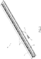
- FIG. 3 includes a schematic perspective view of a blockout structure 30, into which linear light fixture 10 can be assembled, according to some exemplary embodiments.
- blockout structure 30 includes an opening and chamber 32 in which linear light fixture 10 can be installed. Ends of blockout structure 30 are capped by end caps 40.
- Blockout structure 30 can also include installation clip structures 34 and installation hinge structures 36 by which linear light fixture 10 can be secured in opening/chamber 32 of blockout structure 30 when linear light fixture 10 is installed in blockout structure 30. Clip structures 34 and hinge structures 36 are described below in more detail.
- blockout structure 30 can be installed in the ground or other mounting platform or medium 38. Specifically, blockout structure 30 can be located in opening 39 in mounting medium 38. Opening 39 can be formed by procedures such as placing blockout structure 30 in place where desired, and then pouring a hardening liquid material such as concrete around blockout structure 30.
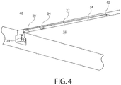
- FIG. 4 includes a schematic perspective view which illustrates blockout structure 30 installed in opening 39 of ground or other mounting platform or medium 38.
- FIG. 5 includes a schematic perspective, partially cut-away view of the linear light fixture 10 of FIG.s. 1 and 2 , installed in blockout structure 30 of FIG. 3 , according to some exemplary embodiments.
- linear light fixture 10 is connected to power and control circuitry 50, 52, 54, 56 by cable 22 and connector 24.
- Power and control circuitry 50, 52, 54, 56 is also located within blockout structure 30, and is connected to the external environment through a conduit 58, which is connected to end cap 18 of blockout structure 30.
- FIG. 6 includes a detailed schematic cross-sectional view of blockout structure 30, according to some exemplary embodiments.
- blockout structure 30 includes opening or chamber 32, into which linear light fixture 10 can be installed.
- FIG. 7 includes a schematic perspective view of linear light fixture 10, connected to power and control circuitry 50 by cable 22 and connector 24, located above blockout structure 30, prior to installation of linear light fixture 10 into opening or chamber 32 of blockout structure 30.
- blockout structure 30 is located in opening 39 in the ground or mounting platform 38.
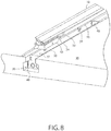
- FIG. 8 includes another schematic perspective view of linear light fixture 10, connected to power and control circuitry 50 by cable 22 and connector 24, located above blockout structure 30, prior to installation of linear light fixture 10 in blockout structure 30.
- blockout structure 30 is located in opening 39 in the ground or mounting platform 38.
- Clip structures 34 of blockout structure 30, which are used to secure linear light fixture 10 in place in blockout structure 30 after installation, are also illustrated in FIG. 8 .
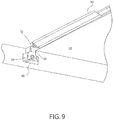
- FIG. 9 includes another schematic perspective view of linear light fixture 10, located partially within opening or chamber 32 of blockout structure 30, during installation of linear light fixture 10 in blockout structure 30.
- blockout structure 30 is located in opening 39 in the ground or mounting platform 38.
- Linear light fixture 10 has been rotated almost completely into the assembled position within blockout structure 30.
- FIG. 10 includes another schematic perspective view of linear light fixture 10, located completely within opening or chamber 32 of blockout structure 30, following installation of linear light fixture 10 in blockout structure 30.
- blockout structure 30 is located in opening 39 in the ground or mounting platform 38.
- Linear light fixture 10 has been rotated completely into the assembled position within blockout structure 30.
- Clip structures 34 of blockout structure 30, which are used to secure linear light fixture 10 in place in blockout structure 30 after installation, have been displaced into the final stationary secure position in which they secure linear light fixture 10 within blockout structure 30, as illustrated and described below in detail.
- FIG. 11A includes a schematic top view of linear light fixture 10, and FIG. 11B is a schematic cross-sectional view of linear light fixture 10, taken along line B-B of FIG. 11A , according to some exemplary embodiments.
- linear light fixture 10 includes a body or chassis portion 12, in which are located one or more light sources 21, which can be light-emitting-diode (LED) light sources.
- the light sources can be arranged in a linear array disposed along the longitudinal axis of chassis 12 and can be covered by cover lens 20, which is not shown in FIGs. 11A and 11B for clarity of illustration.
- Light fixture 10 also includes surface mount flange portions 14 and 16 at which light fixture 10 can be mounted within in-ground blockout 30 (not shown in FIGs. 11A and 11B ). In some exemplary embodiments, fixture 10 is mounted within the in-ground blockout structure 30, flush with the ground, via flange portions 14 and 16.
- Flange mount portion 16 is adjacent to an installation hinge 17, which mates with and operates in concert with installation hinge structure 36 on blockout structure 30 during installation of linear light fixture 10 in blockout structure 30 and after installation to hold linear light fixture 10 in place within blockout structure 30.
- Flange mount portion 14 is adjacent to a flexible installation clip 15, which mates with and operates in concert with installation clip structure 34 on blockout structure 30 during installation of linear light fixture 10 in blockout structure 30 and after installation to hold linear light fixture 10 in place within blockout structure 30.
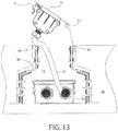
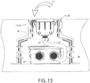
- FIGs. 12 , 13 , 14A, 14B and 15 include schematic cross-sectional diagrams illustrating linear light fixture 10 and blockout structure 30, during a sequence of steps in the process of installing linear light fixture 10 into blockout structure 30.
- FIG. 12 the process of installing linear light fixture 10 into blockout structure 30 has begun with power and control circuitry 50 being loaded into opening or chamber 32 of blockout structure 30.
- FIG. 13 power and control circuitry 50 has been loaded into chamber 32 of blockout structure 30 and positioned in place at the bottom of chamber 32.
- Linear light fixture 10 is located at the top of opening or chamber 32, in preparation for installation.
- FIG. 14B is a detailed view of a portion of FIG. 14A , as indicated by dashed detail circle "A" in FIGs.
- FIGs. 14A and 14B the process of installing linear light fixture 10 in place has begun.
- Installation hinge 17 on linear light fixture 10 has been mated with installation hinge structure 36 on blockout structure 30.
- FIG. 15 linear light fixture 10 is then rotated about the mated installation hinges 17 and 36, as indicated by arrow 11.
- flexible installation clip 15 engages the inner wall of opening or chamber 32 of blockout structure 30 and is elastically deflected away from the inner wall.
- installation clip 15 is translated down into opening or chamber 32 until it reaches an opening in the inner wall at installation clip structure 34 on blockout structure 30.
- installation clip 15 snaps into engagement with the opening in the inner wall, such that installation clip 15 mates with and operates in concert with installation clip structure 34 on blockout structure 30 to hold linear light fixture 10 in place within blockout structure 30, as illustrated in FIG. 15 . This completes the process of installing linear light fixture 10 into blockout structure 30.
- linear light fixture 10 can be disassembled from blockout structure 30 using a disassembly tool, according to exemplary embodiments.
- FIGs. 16A and 16B include schematic perspective views of the assembled linear light fixture 10 and blockout structure 30, along with a disassembly tool 100, according to exemplary embodiments.
- FIG. 16B is a detailed view of a portion of FIG. 16A , as indicated by dashed detail circle "C" in FIGs. 16A and 16B .
- flange portion 14 of linear light fixture 10 includes slots or openings 102 to allow access to clip structures 34.
- Edge portions 104 of tool 100 are insertable into slots 102 to engage installation clip structures 34 to release the installation clip structures 34 such that linear light fixture 10 can be disassembled from blockout structure 30.
- FIG. 17 includes a detailed perspective view of disassembly tool 100, according to some exemplary embodiments.
- disassembly tool 100 includes a front insertion surface 103 and two substantially parallel edge portions 104. As described above, edge portions 104 of tool 100 are insertable into slots 102 to engage installation clip structures 34 to release the installation clip structures 34 such that linear light fixture 10 can be disassembled from blockout structure 30.
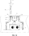
- FIG. 18 includes a schematic cross-sectional diagram illustrating linear light fixture 10 and blockout structure 30 completely assembled, according to exemplary embodiments.
- FIG. 18 is the same as FIG. 15 described in detail above, except for the addition of disassembly tool 100.
- Disassembly tool 100 is schematically illustrated in position to be inserted into the light fixture and blockout assembly to release installation clip 34, such that linear light fixture 10 can be disassembled from blockout structure 30. Insertion of tool 100, which includes front insertion surface 103 and edge portions 104, is pictorially indicated by arrow 101.
- FIG. 19 includes a schematic cross-sectional diagram illustrating linear light fixture 10 and blockout structure 30 completely assembled, at the beginning of the disassembly process using disassembly tool 100, according to exemplary embodiments.
- disassembly tool 100 is shown inserted into the assembly and has engaged installation clip 15 such that installation clip 15 has been released out of engagement with installation clip structure 34 of blockout structure 30.
- linear light fixture 10 is now free to be disassembled from blockout structure 30.
- FIG. 20 includes a schematic cross-sectional diagram illustrating linear light fixture 10 and blockout structure 30 being disassembled, according to exemplary embodiments.
- 34 linear light fixture 10 can be rotated about hinge structure 17, 36 out of chamber 32 of blockout structure 30, as indicated by arrow 105.
- the remainder of the disassembly process is essentially the reverse of the assembly process described above in detail.
- FIGs. 21A and 21B are additional schematic cross-sectional views of the assembled linear light fixture 10 and blockout structure 30 being disassembled using disassembly tool 30, according to some exemplary embodiments.
- disassembly tool 100 has not yet been inserted. Accordingly, installation clip 15 is still engaged with clip structure 34 in blockout 30, thus holding linear light fixture 10 and blockout structure assembled together.
- disassembly tool 100 has been inserted, such that installation clip 15 is displaced and released, and linear light fixture 10 and blockout structure 30 can be disassembled, as described above in detail.
- blockout structure 30 provides for drainage of liquids such as water away from blockout structure 30, such that flooding of blockout structure 30 and resulting damage to any installed light fixture 10 is avoided.
- FIGs. 22 and 23 include schematic cross-sectional views of installation of blockout structure 30 to provide for proper drainage, according to some exemplary embodiments.
- FIG. 22 includes a schematic cross-sectional view of preparation of the installation environment for blockout structure 30, using concrete, according to some exemplary embodiments; and
- FIG. 23 includes a schematic cross-sectional view of preparation of the installation environment for blockout structure 30, using soil, concrete, and a drainage material, according to some exemplary embodiments.
- a ground hole is provided with proper drainage piping underneath the installation location of the blockout structure 30.
- a drainage pipe 78 is provided in the concrete 70.
- Anchor holes 72 are also formed in concrete 70.
- Anchors 74 are installed in anchor holes 72, and blockout structure 30 is located with threaded portions of anchors 74 penetrating vertically up through openings in mounting flange portions 73 of blockout structure 30.
- Nuts 76 are threaded onto anchors 74 to secure blockout structure 30 in place. Any fluids such as water entering the space 75 adjacent to blockout structure 30 will be carried away via drainage pipe 78, thus preventing flooding of blockout structure 30.
- FIG. 23 in the illustrated "concrete-and-soil" installation, a ground hole is provided surrounded by soil 80.
- Appropriate drainage material 82 such as sand or other similar material, is provided underneath the installation location of the blockout structure 30.
- Blockout retainers 86 are inserted through openings in mounting flange portions 73 of blockout structure 30 to hold blockout structure stationary during a subsequent concrete pour, indicated pictorially by 88.
- FIG. 24 includes a schematic cross-sectional diagram which illustrates the installation configuration of FIG. 23 , after concrete 88 has cured. Any fluids such as water under blockout structure 30 will be carried away via drainage material 82, thus preventing flooding of blockout structure 30.
- blockout structure 30 is configured to include a drainage capability to ensure that any fluids such as water entering the structure from the top or ground level, will be carried through blockout structure 30, around any light fixture 10 which may be installed in blockout structure 30, to the drainage system at the bottom of the blockout structure, and away from the assembly.
- blockout structure 30 includes open channels which run down along the sides of blockout structure 30, so that any fluids can be carried away to system drainage, i.e., drainage pipe 78 or drainage material 82, without entering light fixture 10.
- system drainage i.e., drainage pipe 78 or drainage material 82
Landscapes
- Engineering & Computer Science (AREA)
- General Engineering & Computer Science (AREA)
- Non-Portable Lighting Devices Or Systems Thereof (AREA)
- Arrangement Of Elements, Cooling, Sealing, Or The Like Of Lighting Devices (AREA)
Claims (9)
- Système d'éclairage comprenant :un appareil d'éclairage linéaire (10) ;une structure de dissimulation linéaire (30) pouvant être montée dans une base du système d'éclairage, l'appareil d'éclairage linéaire (10) pouvant être monté dans la structure de dissimulation linéaire (30) lorsque l'appareil d'éclairage linéaire (10) et la structure de dissimulation linéaire (30) sont assemblés ensemble, la structure de dissimulation linéaire (30) comprenant une chambre (32) dans laquelle l'appareil d'éclairage linéaire (10) peut être monté et des parois latérales sur des côtés opposés de la chambre (32) pouvant être mis en prise par des parties brides (14, 16) de l'appareil d'éclairage linéaire (10) lorsque l'appareil d'éclairage linéaire (10) et la structure de dissimulation linéaire (30) sont assemblés ensemble ;une structure de charnière comprenant un premier composant de charnière (36) sur une première paroi latérale de la structure de dissimulation linéaire (30) et un second composant de charnière (17) sur une première partie bride (16) de l'appareil d'éclairage linéaire (10), les premier et second composants de charnière se mettant en prise l'un avec l'autre de sorte que lorsque la structure de dissimulation linéaire (30) et l'appareil d'éclairage linéaire (10) sont assemblés, la structure de dissimulation linéaire (30) et l'appareil d'éclairage linéaire (10) peuvent tourner l'un par rapport à l'autre au niveau de la structure de charnière ;et une structure de fixation comprenant un premier composant de fixation sur une seconde partie bride (14) de l'appareil d'éclairage linéaire (10) et un second composant de fixation sur une seconde paroi latérale de la structure de dissimulation linéaire (30), les premier et second composants de fixation, venant en prise l'un avec l'autre pour maintenir la structure de dissimulation linéaire (30) et l'appareil d'éclairage linéaire (10) assemblés ensemble avec l'appareil d'éclairage linéaire (10), étant disposés dans la chambre (32) de la structure de dissimulation linéaire, ladite seconde partie bride (14) de l'appareil d'éclairage linéaire (10) comprenant une ou plusieurs ouvertures (102) permettant un accès à la structure de fixation de sorte que les premier et second composants de fixation puissent être désengagés l'un de l'autre de sorte que l'appareil d'éclairage linéaire (10) et la structure de dissimulation linéaire (30) puissent être désassemblés l'un de l'autre.
- Système d'éclairage selon la revendication 1, ledit premier composant de fixation comprenant une bride à encliquetage souple (15) et ledit second composant de fixation comprenant une ouverture dans la seconde paroi latérale de la structure de dissimulation linéaire (30), ladite bride à encliquetage souple (15) étant déplacée en prise avec l'ouverture lorsque la structure de dissimulation linéaire (30) et l'appareil d'éclairage linéaire (10) sont assemblés ensemble.
- Système d'éclairage selon la revendication 1 ou 2, ladite structure de charnière et ladite structure de fixation étant conçues de sorte que, durant l'assemblage de l'appareil d'éclairage linéaire (10) et de la structure de dissimulation linéaire (30), l'appareil d'éclairage linéaire (10) et la structure de dissimulation linéaire (30) tournent autour de la structure de charnière de sorte qu'au niveau d'une première position de rotation, la structure de dissimulation linéaire (30) se mette en prise physiquement avec la bride à encliquetage souple (15) pour dévier la bride à encliquetage souple (15), et qu'au niveau d'une seconde position de rotation, la bride à encliquetage souple (15) soit libérée dans l'ouverture de la seconde paroi latérale de la structure de dissimulation linéaire (30) pour maintenir l'appareil d'éclairage linéaire (10) et la structure de dissimulation linéaire (30) dans une configuration assemblée.
- Système d'éclairage selon la revendication 3, comprenant en outre un outil de désassemblage (100) conçu pour être inséré dans la ou les ouvertures (102) afin de venir en prise avec la bride à encliquetage souple (15) afin de dévier la bride à encliquetage souple (15) hors de l'ouverture dans la seconde paroi latérale de la structure de dissimulation linéaire (30) pour permettre à l'appareil d'éclairage linéaire (10) et à la structure de dissimulation linéaire (30) d'être désassemblés l'un de l'autre.
- Système d'éclairage selon la revendication 3, comprenant en outre un outil de désassemblage (100) conçu pour être inséré dans la ou les ouvertures (102) afin de désengager la structure de fixation.
- Système d'éclairage selon la revendication 1, ladite base du système d'éclairage comprenant du béton (70).
- Système d'éclairage selon la revendication 1, ladite base du système d'éclairage comprenant de la terre (80).
- Système d'éclairage selon la revendication 1, ladite base du système d'éclairage comprenant un matériau de drainage (82).
- Système d'éclairage selon la revendication 1, ladite base du système d'éclairage comprenant un tuyau de drainage (78).
Applications Claiming Priority (2)
| Application Number | Priority Date | Filing Date | Title |
|---|---|---|---|
| US201462003463P | 2014-05-27 | 2014-05-27 | |
| PCT/IB2015/001631 WO2015181643A2 (fr) | 2014-05-27 | 2015-05-27 | Système d'appareil d'éclairage dans le sol avec mécanisme de fermeture d'installation et drainage améliorés |
Publications (3)
| Publication Number | Publication Date |
|---|---|
| EP3149401A2 EP3149401A2 (fr) | 2017-04-05 |
| EP3149401A4 EP3149401A4 (fr) | 2017-11-15 |
| EP3149401B1 true EP3149401B1 (fr) | 2019-10-23 |
Family
ID=54699991
Family Applications (1)
| Application Number | Title | Priority Date | Filing Date |
|---|---|---|---|
| EP15800457.2A Active EP3149401B1 (fr) | 2014-05-27 | 2015-05-27 | Système d'appareil d'éclairage dans le sol avec mécanisme de fermeture d'installation et drainage améliorés |
Country Status (4)
| Country | Link |
|---|---|
| US (1) | US9638381B2 (fr) |
| EP (1) | EP3149401B1 (fr) |
| CA (1) | CA2946986C (fr) |
| WO (1) | WO2015181643A2 (fr) |
Families Citing this family (8)
| Publication number | Priority date | Publication date | Assignee | Title |
|---|---|---|---|---|
| US11242981B2 (en) * | 2018-11-13 | 2022-02-08 | Qtran, Inc. | Recessed lighting fixture |
| US11767953B2 (en) | 2019-06-13 | 2023-09-26 | Laurence Robert St.Ives | Cast in-ground lighting assembly |
| US10557600B1 (en) * | 2019-10-16 | 2020-02-11 | Elemental LED, Inc. | In-ground channel systems for linear lighting |
| IT202300003693A1 (it) * | 2023-03-01 | 2024-09-01 | Flos Spa | Assieme di illuminazione |
| IT202300003690A1 (it) * | 2023-03-01 | 2024-09-01 | Flos Spa | Assieme di illuminazione |
| USD1092818S1 (en) * | 2023-09-12 | 2025-09-09 | Patina Lighting Limited | Lighting apparatus |
| USD1092819S1 (en) * | 2023-09-12 | 2025-09-09 | Patina Lighting Limited | Lighting apparatus |
| US20260063279A1 (en) * | 2024-09-04 | 2026-03-05 | Bellson Electric Pty Ltd | Adjustable track for lighting device for pools |
Family Cites Families (12)
| Publication number | Priority date | Publication date | Assignee | Title |
|---|---|---|---|---|
| DE7211776U (de) * | 1972-06-29 | Roth P | Elektrische Wohnwagenleuchte | |
| US4035632A (en) | 1975-04-29 | 1977-07-12 | Rayman Robert R | Fixture system |
| FR2611071B1 (fr) * | 1987-02-18 | 1991-10-31 | Villard Jean | Panneau lumineux pour publicite au sol |
| US6220731B1 (en) | 1998-11-10 | 2001-04-24 | Altman Stage Lighting Co., Inc. | Cyclorama light |
| US7080923B2 (en) | 2002-11-30 | 2006-07-25 | Genlyte Thomas Group, Llc | Surface mount fluorescent strip light fixture retrofit kit and method |
| US6942364B1 (en) | 2003-05-02 | 2005-09-13 | Acuity Brands, Inc. | Luminaires having aperture-modifying structures for producing visually smooth light distributions |
| US7347606B1 (en) * | 2004-06-18 | 2008-03-25 | Patten Gregg M | Rope light track system |
| US8590087B2 (en) * | 2004-12-14 | 2013-11-26 | Rite-Hite Holding Corporation | Lighting and signaling systems for loading docks |
| US20070070618A1 (en) * | 2005-09-27 | 2007-03-29 | Talamo John A | Lighted guide strip |
| US20080253133A1 (en) | 2007-03-30 | 2008-10-16 | Cooper Technologies Company | Reflectors for luminaires |
| IT1390984B1 (it) * | 2008-08-21 | 2011-10-27 | Gewiss Spa | Struttura di illuminazione da incasso |
| IT1392934B1 (it) * | 2009-02-20 | 2012-04-02 | Aldabra Srl | Dispositivo di illuminazione dotato di un componente ottico di propagazione della radiazione luminosa |
-
2015
- 2015-05-26 US US14/721,180 patent/US9638381B2/en active Active
- 2015-05-27 EP EP15800457.2A patent/EP3149401B1/fr active Active
- 2015-05-27 WO PCT/IB2015/001631 patent/WO2015181643A2/fr not_active Ceased
- 2015-05-27 CA CA2946986A patent/CA2946986C/fr active Active
Non-Patent Citations (1)
| Title |
|---|
| None * |
Also Published As
| Publication number | Publication date |
|---|---|
| US9638381B2 (en) | 2017-05-02 |
| US20150345722A1 (en) | 2015-12-03 |
| CA2946986C (fr) | 2020-09-01 |
| CA2946986A1 (fr) | 2015-12-03 |
| EP3149401A2 (fr) | 2017-04-05 |
| WO2015181643A2 (fr) | 2015-12-03 |
| WO2015181643A3 (fr) | 2016-03-03 |
| EP3149401A4 (fr) | 2017-11-15 |
Similar Documents
| Publication | Publication Date | Title |
|---|---|---|
| EP3149401B1 (fr) | Système d'appareil d'éclairage dans le sol avec mécanisme de fermeture d'installation et drainage améliorés | |
| US5051875A (en) | Underwater pool light | |
| KR101983995B1 (ko) | 공동주택 건축물의 전기케이블 보호장치 | |
| WO2014152441A1 (fr) | Montage et verrouillage d'un appareil d'éclairage | |
| US9175839B2 (en) | Universal mounting system for a light fixture | |
| US11125400B2 (en) | Outdoor light fixtures | |
| US9466962B1 (en) | Rain tight electrical box assembly for mounting of an electrical fan or fixture | |
| US9074367B2 (en) | Assembly for a line conduit | |
| CA2612346C (fr) | Dispositif helicoidal pour appareil d'eclairage encastre | |
| KR101166143B1 (ko) | 천정 매립등의 하우징 고정용 스프링장치 | |
| KR20190000492U (ko) | 배관 고정 장치 | |
| KR20090101066A (ko) | 설치각도 가변형 조립식 맨홀 | |
| AU2010246459B2 (en) | Downlight Housing | |
| CA2822403A1 (fr) | Elements constitutifs pour la lecture automatique de compteurs | |
| US12516793B2 (en) | Housing for light fixture | |
| US10267497B2 (en) | Easy install light engine retrofit kit and method for using same | |
| JP5906385B2 (ja) | 照明器具 | |
| EA036527B1 (ru) | Устройство и способ для изготовления отверстия в канале в системе каналов, выполненной в пространстве для прокладки коммуникаций здания | |
| KR100880802B1 (ko) | 설치각도 가변형 조립식 맨홀 | |
| RU133658U1 (ru) | Коробка монтажная | |
| KR200462071Y1 (ko) | 천정 매입형 조명기구의 행거 구조물 | |
| KR200375107Y1 (ko) | 옥내 천장 배선용 접속함의 커버 | |
| EP1908156A1 (fr) | Boitier de lampadaire de plafond en beton | |
| US20200288925A1 (en) | Toilet flange assembly and method for installing a toilet | |
| US20210080097A1 (en) | Conversion adapter for pool and spa lighting hardware |
Legal Events
| Date | Code | Title | Description |
|---|---|---|---|
| STAA | Information on the status of an ep patent application or granted ep patent |
Free format text: STATUS: THE INTERNATIONAL PUBLICATION HAS BEEN MADE |
|
| PUAI | Public reference made under article 153(3) epc to a published international application that has entered the european phase |
Free format text: ORIGINAL CODE: 0009012 |
|
| STAA | Information on the status of an ep patent application or granted ep patent |
Free format text: STATUS: REQUEST FOR EXAMINATION WAS MADE |
|
| 17P | Request for examination filed |
Effective date: 20161220 |
|
| AK | Designated contracting states |
Kind code of ref document: A2 Designated state(s): AL AT BE BG CH CY CZ DE DK EE ES FI FR GB GR HR HU IE IS IT LI LT LU LV MC MK MT NL NO PL PT RO RS SE SI SK SM TR |
|
| AX | Request for extension of the european patent |
Extension state: BA ME |
|
| DAV | Request for validation of the european patent (deleted) | ||
| DAX | Request for extension of the european patent (deleted) | ||
| A4 | Supplementary search report drawn up and despatched |
Effective date: 20171018 |
|
| RIC1 | Information provided on ipc code assigned before grant |
Ipc: F21V 17/16 20060101ALN20171012BHEP Ipc: F21S 8/00 20060101AFI20171012BHEP Ipc: F21Y 115/10 20160101ALN20171012BHEP Ipc: F21W 131/10 20060101ALN20171012BHEP Ipc: F21V 21/30 20060101ALI20171012BHEP |
|
| RAP1 | Party data changed (applicant data changed or rights of an application transferred) |
Owner name: LUMENPULSE LIGHTING INC. |
|
| RAP1 | Party data changed (applicant data changed or rights of an application transferred) |
Owner name: LUMENPULSE GROUP INC. |
|
| RIC1 | Information provided on ipc code assigned before grant |
Ipc: F21Y 115/10 20160101ALN20190313BHEP Ipc: F21W 131/10 20060101ALN20190313BHEP Ipc: F21S 8/02 20060101AFI20190313BHEP Ipc: F21V 17/10 20060101ALI20190313BHEP Ipc: F21V 21/30 20060101ALI20190313BHEP |
|
| GRAP | Despatch of communication of intention to grant a patent |
Free format text: ORIGINAL CODE: EPIDOSNIGR1 |
|
| STAA | Information on the status of an ep patent application or granted ep patent |
Free format text: STATUS: GRANT OF PATENT IS INTENDED |
|
| INTG | Intention to grant announced |
Effective date: 20190604 |
|
| GRAJ | Information related to disapproval of communication of intention to grant by the applicant or resumption of examination proceedings by the epo deleted |
Free format text: ORIGINAL CODE: EPIDOSDIGR1 |
|
| STAA | Information on the status of an ep patent application or granted ep patent |
Free format text: STATUS: REQUEST FOR EXAMINATION WAS MADE |
|
| REG | Reference to a national code |
Ref country code: DE Ref legal event code: R079 Ref document number: 602015040403 Country of ref document: DE Free format text: PREVIOUS MAIN CLASS: F21V0017000000 Ipc: F21S0008020000 |
|
| GRAP | Despatch of communication of intention to grant a patent |
Free format text: ORIGINAL CODE: EPIDOSNIGR1 |
|
| STAA | Information on the status of an ep patent application or granted ep patent |
Free format text: STATUS: GRANT OF PATENT IS INTENDED |
|
| INTC | Intention to grant announced (deleted) | ||
| INTG | Intention to grant announced |
Effective date: 20190814 |
|
| RIC1 | Information provided on ipc code assigned before grant |
Ipc: F21V 21/30 20060101ALI20190805BHEP Ipc: F21W 131/10 20060101ALN20190805BHEP Ipc: F21Y 115/10 20160101ALN20190805BHEP Ipc: F21S 8/02 20060101AFI20190805BHEP Ipc: F21V 17/10 20060101ALI20190805BHEP |
|
| GRAS | Grant fee paid |
Free format text: ORIGINAL CODE: EPIDOSNIGR3 |
|
| GRAA | (expected) grant |
Free format text: ORIGINAL CODE: 0009210 |
|
| STAA | Information on the status of an ep patent application or granted ep patent |
Free format text: STATUS: THE PATENT HAS BEEN GRANTED |
|
| AK | Designated contracting states |
Kind code of ref document: B1 Designated state(s): AL AT BE BG CH CY CZ DE DK EE ES FI FR GB GR HR HU IE IS IT LI LT LU LV MC MK MT NL NO PL PT RO RS SE SI SK SM TR |
|
| REG | Reference to a national code |
Ref country code: GB Ref legal event code: FG4D |
|
| REG | Reference to a national code |
Ref country code: CH Ref legal event code: EP |
|
| REG | Reference to a national code |
Ref country code: IE Ref legal event code: FG4D |
|
| REG | Reference to a national code |
Ref country code: DE Ref legal event code: R096 Ref document number: 602015040403 Country of ref document: DE |
|
| REG | Reference to a national code |
Ref country code: AT Ref legal event code: REF Ref document number: 1194046 Country of ref document: AT Kind code of ref document: T Effective date: 20191115 |
|
| REG | Reference to a national code |
Ref country code: NL Ref legal event code: MP Effective date: 20191023 |
|
| REG | Reference to a national code |
Ref country code: LT Ref legal event code: MG4D |
|
| PG25 | Lapsed in a contracting state [announced via postgrant information from national office to epo] |
Ref country code: FI Free format text: LAPSE BECAUSE OF FAILURE TO SUBMIT A TRANSLATION OF THE DESCRIPTION OR TO PAY THE FEE WITHIN THE PRESCRIBED TIME-LIMIT Effective date: 20191023 Ref country code: BG Free format text: LAPSE BECAUSE OF FAILURE TO SUBMIT A TRANSLATION OF THE DESCRIPTION OR TO PAY THE FEE WITHIN THE PRESCRIBED TIME-LIMIT Effective date: 20200123 Ref country code: GR Free format text: LAPSE BECAUSE OF FAILURE TO SUBMIT A TRANSLATION OF THE DESCRIPTION OR TO PAY THE FEE WITHIN THE PRESCRIBED TIME-LIMIT Effective date: 20200124 Ref country code: LT Free format text: LAPSE BECAUSE OF FAILURE TO SUBMIT A TRANSLATION OF THE DESCRIPTION OR TO PAY THE FEE WITHIN THE PRESCRIBED TIME-LIMIT Effective date: 20191023 Ref country code: PT Free format text: LAPSE BECAUSE OF FAILURE TO SUBMIT A TRANSLATION OF THE DESCRIPTION OR TO PAY THE FEE WITHIN THE PRESCRIBED TIME-LIMIT Effective date: 20200224 Ref country code: NL Free format text: LAPSE BECAUSE OF FAILURE TO SUBMIT A TRANSLATION OF THE DESCRIPTION OR TO PAY THE FEE WITHIN THE PRESCRIBED TIME-LIMIT Effective date: 20191023 Ref country code: PL Free format text: LAPSE BECAUSE OF FAILURE TO SUBMIT A TRANSLATION OF THE DESCRIPTION OR TO PAY THE FEE WITHIN THE PRESCRIBED TIME-LIMIT Effective date: 20191023 Ref country code: NO Free format text: LAPSE BECAUSE OF FAILURE TO SUBMIT A TRANSLATION OF THE DESCRIPTION OR TO PAY THE FEE WITHIN THE PRESCRIBED TIME-LIMIT Effective date: 20200123 Ref country code: LV Free format text: LAPSE BECAUSE OF FAILURE TO SUBMIT A TRANSLATION OF THE DESCRIPTION OR TO PAY THE FEE WITHIN THE PRESCRIBED TIME-LIMIT Effective date: 20191023 Ref country code: SE Free format text: LAPSE BECAUSE OF FAILURE TO SUBMIT A TRANSLATION OF THE DESCRIPTION OR TO PAY THE FEE WITHIN THE PRESCRIBED TIME-LIMIT Effective date: 20191023 |
|
| PG25 | Lapsed in a contracting state [announced via postgrant information from national office to epo] |
Ref country code: IS Free format text: LAPSE BECAUSE OF FAILURE TO SUBMIT A TRANSLATION OF THE DESCRIPTION OR TO PAY THE FEE WITHIN THE PRESCRIBED TIME-LIMIT Effective date: 20200224 Ref country code: RS Free format text: LAPSE BECAUSE OF FAILURE TO SUBMIT A TRANSLATION OF THE DESCRIPTION OR TO PAY THE FEE WITHIN THE PRESCRIBED TIME-LIMIT Effective date: 20191023 Ref country code: HR Free format text: LAPSE BECAUSE OF FAILURE TO SUBMIT A TRANSLATION OF THE DESCRIPTION OR TO PAY THE FEE WITHIN THE PRESCRIBED TIME-LIMIT Effective date: 20191023 |
|
| PG25 | Lapsed in a contracting state [announced via postgrant information from national office to epo] |
Ref country code: AL Free format text: LAPSE BECAUSE OF FAILURE TO SUBMIT A TRANSLATION OF THE DESCRIPTION OR TO PAY THE FEE WITHIN THE PRESCRIBED TIME-LIMIT Effective date: 20191023 |
|
| REG | Reference to a national code |
Ref country code: DE Ref legal event code: R097 Ref document number: 602015040403 Country of ref document: DE |
|
| PG2D | Information on lapse in contracting state deleted |
Ref country code: IS |
|
| PG25 | Lapsed in a contracting state [announced via postgrant information from national office to epo] |
Ref country code: ES Free format text: LAPSE BECAUSE OF FAILURE TO SUBMIT A TRANSLATION OF THE DESCRIPTION OR TO PAY THE FEE WITHIN THE PRESCRIBED TIME-LIMIT Effective date: 20191023 Ref country code: CZ Free format text: LAPSE BECAUSE OF FAILURE TO SUBMIT A TRANSLATION OF THE DESCRIPTION OR TO PAY THE FEE WITHIN THE PRESCRIBED TIME-LIMIT Effective date: 20191023 Ref country code: RO Free format text: LAPSE BECAUSE OF FAILURE TO SUBMIT A TRANSLATION OF THE DESCRIPTION OR TO PAY THE FEE WITHIN THE PRESCRIBED TIME-LIMIT Effective date: 20191023 Ref country code: EE Free format text: LAPSE BECAUSE OF FAILURE TO SUBMIT A TRANSLATION OF THE DESCRIPTION OR TO PAY THE FEE WITHIN THE PRESCRIBED TIME-LIMIT Effective date: 20191023 Ref country code: DK Free format text: LAPSE BECAUSE OF FAILURE TO SUBMIT A TRANSLATION OF THE DESCRIPTION OR TO PAY THE FEE WITHIN THE PRESCRIBED TIME-LIMIT Effective date: 20191023 Ref country code: IS Free format text: LAPSE BECAUSE OF FAILURE TO SUBMIT A TRANSLATION OF THE DESCRIPTION OR TO PAY THE FEE WITHIN THE PRESCRIBED TIME-LIMIT Effective date: 20200223 |
|
| REG | Reference to a national code |
Ref country code: AT Ref legal event code: MK05 Ref document number: 1194046 Country of ref document: AT Kind code of ref document: T Effective date: 20191023 |
|
| PLBE | No opposition filed within time limit |
Free format text: ORIGINAL CODE: 0009261 |
|
| STAA | Information on the status of an ep patent application or granted ep patent |
Free format text: STATUS: NO OPPOSITION FILED WITHIN TIME LIMIT |
|
| PG25 | Lapsed in a contracting state [announced via postgrant information from national office to epo] |
Ref country code: SK Free format text: LAPSE BECAUSE OF FAILURE TO SUBMIT A TRANSLATION OF THE DESCRIPTION OR TO PAY THE FEE WITHIN THE PRESCRIBED TIME-LIMIT Effective date: 20191023 Ref country code: SM Free format text: LAPSE BECAUSE OF FAILURE TO SUBMIT A TRANSLATION OF THE DESCRIPTION OR TO PAY THE FEE WITHIN THE PRESCRIBED TIME-LIMIT Effective date: 20191023 |
|
| 26N | No opposition filed |
Effective date: 20200724 |
|
| REG | Reference to a national code |
Ref country code: DE Ref legal event code: R082 Ref document number: 602015040403 Country of ref document: DE Representative=s name: VENNER SHIPLEY GERMANY LLP, DE Ref country code: DE Ref legal event code: R082 Ref document number: 602015040403 Country of ref document: DE Representative=s name: VENNER SHIPLEY LLP, DE |
|
| PG25 | Lapsed in a contracting state [announced via postgrant information from national office to epo] |
Ref country code: AT Free format text: LAPSE BECAUSE OF FAILURE TO SUBMIT A TRANSLATION OF THE DESCRIPTION OR TO PAY THE FEE WITHIN THE PRESCRIBED TIME-LIMIT Effective date: 20191023 Ref country code: SI Free format text: LAPSE BECAUSE OF FAILURE TO SUBMIT A TRANSLATION OF THE DESCRIPTION OR TO PAY THE FEE WITHIN THE PRESCRIBED TIME-LIMIT Effective date: 20191023 |
|
| PG25 | Lapsed in a contracting state [announced via postgrant information from national office to epo] |
Ref country code: CH Free format text: LAPSE BECAUSE OF NON-PAYMENT OF DUE FEES Effective date: 20200531 Ref country code: MC Free format text: LAPSE BECAUSE OF FAILURE TO SUBMIT A TRANSLATION OF THE DESCRIPTION OR TO PAY THE FEE WITHIN THE PRESCRIBED TIME-LIMIT Effective date: 20191023 Ref country code: LI Free format text: LAPSE BECAUSE OF NON-PAYMENT OF DUE FEES Effective date: 20200531 |
|
| REG | Reference to a national code |
Ref country code: BE Ref legal event code: MM Effective date: 20200531 |
|
| PG25 | Lapsed in a contracting state [announced via postgrant information from national office to epo] |
Ref country code: LU Free format text: LAPSE BECAUSE OF NON-PAYMENT OF DUE FEES Effective date: 20200527 |
|
| PG25 | Lapsed in a contracting state [announced via postgrant information from national office to epo] |
Ref country code: IE Free format text: LAPSE BECAUSE OF NON-PAYMENT OF DUE FEES Effective date: 20200527 |
|
| PG25 | Lapsed in a contracting state [announced via postgrant information from national office to epo] |
Ref country code: BE Free format text: LAPSE BECAUSE OF NON-PAYMENT OF DUE FEES Effective date: 20200531 |
|
| REG | Reference to a national code |
Ref country code: DE Ref legal event code: R081 Ref document number: 602015040403 Country of ref document: DE Owner name: LMPG INC., LONGUEUIL, CA Free format text: FORMER OWNER: LUMENPULSE GROUP INC., LONGUEUIL, CA |
|
| PG25 | Lapsed in a contracting state [announced via postgrant information from national office to epo] |
Ref country code: TR Free format text: LAPSE BECAUSE OF FAILURE TO SUBMIT A TRANSLATION OF THE DESCRIPTION OR TO PAY THE FEE WITHIN THE PRESCRIBED TIME-LIMIT Effective date: 20191023 Ref country code: MT Free format text: LAPSE BECAUSE OF FAILURE TO SUBMIT A TRANSLATION OF THE DESCRIPTION OR TO PAY THE FEE WITHIN THE PRESCRIBED TIME-LIMIT Effective date: 20191023 Ref country code: CY Free format text: LAPSE BECAUSE OF FAILURE TO SUBMIT A TRANSLATION OF THE DESCRIPTION OR TO PAY THE FEE WITHIN THE PRESCRIBED TIME-LIMIT Effective date: 20191023 |
|
| PG25 | Lapsed in a contracting state [announced via postgrant information from national office to epo] |
Ref country code: MK Free format text: LAPSE BECAUSE OF FAILURE TO SUBMIT A TRANSLATION OF THE DESCRIPTION OR TO PAY THE FEE WITHIN THE PRESCRIBED TIME-LIMIT Effective date: 20191023 |
|
| PGFP | Annual fee paid to national office [announced via postgrant information from national office to epo] |
Ref country code: DE Payment date: 20250519 Year of fee payment: 11 |
|
| PGFP | Annual fee paid to national office [announced via postgrant information from national office to epo] |
Ref country code: GB Payment date: 20250516 Year of fee payment: 11 |
|
| PGFP | Annual fee paid to national office [announced via postgrant information from national office to epo] |
Ref country code: IT Payment date: 20250516 Year of fee payment: 11 |
|
| PGFP | Annual fee paid to national office [announced via postgrant information from national office to epo] |
Ref country code: FR Payment date: 20250516 Year of fee payment: 11 |