EP3149406B1 - Soupape de régulation de gaz, table de cuisson et cuisinière à gaz - Google Patents
Soupape de régulation de gaz, table de cuisson et cuisinière à gaz Download PDFInfo
- Publication number
- EP3149406B1 EP3149406B1 EP15788476.8A EP15788476A EP3149406B1 EP 3149406 B1 EP3149406 B1 EP 3149406B1 EP 15788476 A EP15788476 A EP 15788476A EP 3149406 B1 EP3149406 B1 EP 3149406B1
- Authority
- EP
- European Patent Office
- Prior art keywords
- gas
- control valve
- gas control
- valve
- valve body
- Prior art date
- Legal status (The legal status is an assumption and is not a legal conclusion. Google has not performed a legal analysis and makes no representation as to the accuracy of the status listed.)
- Active
Links
Images



Classifications
-
- F—MECHANICAL ENGINEERING; LIGHTING; HEATING; WEAPONS; BLASTING
- F16—ENGINEERING ELEMENTS AND UNITS; GENERAL MEASURES FOR PRODUCING AND MAINTAINING EFFECTIVE FUNCTIONING OF MACHINES OR INSTALLATIONS; THERMAL INSULATION IN GENERAL
- F16K—VALVES; TAPS; COCKS; ACTUATING-FLOATS; DEVICES FOR VENTING OR AERATING
- F16K5/00—Plug valves; Taps or cocks comprising only cut-off apparatus having at least one of the sealing faces shaped as a more or less complete surface of a solid of revolution, the opening and closing movement being predominantly rotary
- F16K5/04—Plug valves; Taps or cocks comprising only cut-off apparatus having at least one of the sealing faces shaped as a more or less complete surface of a solid of revolution, the opening and closing movement being predominantly rotary with plugs having cylindrical surfaces; Packings therefor
-
- F—MECHANICAL ENGINEERING; LIGHTING; HEATING; WEAPONS; BLASTING
- F24—HEATING; RANGES; VENTILATING
- F24C—DOMESTIC STOVES OR RANGES ; DETAILS OF DOMESTIC STOVES OR RANGES, OF GENERAL APPLICATION
- F24C3/00—Stoves or ranges for gaseous fuels
- F24C3/12—Arrangement or mounting of control or safety devices
- F24C3/124—Control panels
-
- G—PHYSICS
- G05—CONTROLLING; REGULATING
- G05G—CONTROL DEVICES OR SYSTEMS INSOFAR AS CHARACTERISED BY MECHANICAL FEATURES ONLY
- G05G1/00—Controlling members, e.g. knobs or handles; Assemblies or arrangements thereof; Indicating position of controlling members
- G05G1/08—Controlling members for hand actuation by rotary movement, e.g. hand wheels
-
- F—MECHANICAL ENGINEERING; LIGHTING; HEATING; WEAPONS; BLASTING
- F23—COMBUSTION APPARATUS; COMBUSTION PROCESSES
- F23N—REGULATING OR CONTROLLING COMBUSTION
- F23N1/00—Regulating fuel supply
-
- A—HUMAN NECESSITIES
- A47—FURNITURE; DOMESTIC ARTICLES OR APPLIANCES; COFFEE MILLS; SPICE MILLS; SUCTION CLEANERS IN GENERAL
- A47J—KITCHEN EQUIPMENT; COFFEE MILLS; SPICE MILLS; APPARATUS FOR MAKING BEVERAGES
- A47J27/00—Cooking-vessels
- A47J27/002—Construction of cooking-vessels; Methods or processes of manufacturing specially adapted for cooking-vessels
-
- A—HUMAN NECESSITIES
- A47—FURNITURE; DOMESTIC ARTICLES OR APPLIANCES; COFFEE MILLS; SPICE MILLS; SUCTION CLEANERS IN GENERAL
- A47J—KITCHEN EQUIPMENT; COFFEE MILLS; SPICE MILLS; APPARATUS FOR MAKING BEVERAGES
- A47J36/00—Parts, details or accessories of cooking-vessels
-
- F—MECHANICAL ENGINEERING; LIGHTING; HEATING; WEAPONS; BLASTING
- F16—ENGINEERING ELEMENTS AND UNITS; GENERAL MEASURES FOR PRODUCING AND MAINTAINING EFFECTIVE FUNCTIONING OF MACHINES OR INSTALLATIONS; THERMAL INSULATION IN GENERAL
- F16K—VALVES; TAPS; COCKS; ACTUATING-FLOATS; DEVICES FOR VENTING OR AERATING
- F16K27/00—Construction of housing; Use of materials therefor
- F16K27/06—Construction of housing; Use of materials therefor of taps or cocks
- F16K27/065—Construction of housing; Use of materials therefor of taps or cocks with cylindrical plugs
-
- F—MECHANICAL ENGINEERING; LIGHTING; HEATING; WEAPONS; BLASTING
- F16—ENGINEERING ELEMENTS AND UNITS; GENERAL MEASURES FOR PRODUCING AND MAINTAINING EFFECTIVE FUNCTIONING OF MACHINES OR INSTALLATIONS; THERMAL INSULATION IN GENERAL
- F16K—VALVES; TAPS; COCKS; ACTUATING-FLOATS; DEVICES FOR VENTING OR AERATING
- F16K31/00—Actuating devices; Operating means; Releasing devices
- F16K31/44—Mechanical actuating means
- F16K31/60—Handles
-
- F—MECHANICAL ENGINEERING; LIGHTING; HEATING; WEAPONS; BLASTING
- F23—COMBUSTION APPARATUS; COMBUSTION PROCESSES
- F23N—REGULATING OR CONTROLLING COMBUSTION
- F23N1/00—Regulating fuel supply
- F23N1/005—Regulating fuel supply using electrical or electromechanical means
-
- F—MECHANICAL ENGINEERING; LIGHTING; HEATING; WEAPONS; BLASTING
- F23—COMBUSTION APPARATUS; COMBUSTION PROCESSES
- F23N—REGULATING OR CONTROLLING COMBUSTION
- F23N1/00—Regulating fuel supply
- F23N1/007—Regulating fuel supply using mechanical means
-
- F—MECHANICAL ENGINEERING; LIGHTING; HEATING; WEAPONS; BLASTING
- F23—COMBUSTION APPARATUS; COMBUSTION PROCESSES
- F23N—REGULATING OR CONTROLLING COMBUSTION
- F23N5/00—Systems for controlling combustion
-
- F—MECHANICAL ENGINEERING; LIGHTING; HEATING; WEAPONS; BLASTING
- F23—COMBUSTION APPARATUS; COMBUSTION PROCESSES
- F23N—REGULATING OR CONTROLLING COMBUSTION
- F23N5/00—Systems for controlling combustion
- F23N5/20—Systems for controlling combustion with a time program acting through electrical means, e.g. using time-delay relays
-
- F—MECHANICAL ENGINEERING; LIGHTING; HEATING; WEAPONS; BLASTING
- F24—HEATING; RANGES; VENTILATING
- F24C—DOMESTIC STOVES OR RANGES ; DETAILS OF DOMESTIC STOVES OR RANGES, OF GENERAL APPLICATION
- F24C3/00—Stoves or ranges for gaseous fuels
- F24C3/02—Stoves or ranges for gaseous fuels with heat produced solely by flame
-
- F—MECHANICAL ENGINEERING; LIGHTING; HEATING; WEAPONS; BLASTING
- F24—HEATING; RANGES; VENTILATING
- F24C—DOMESTIC STOVES OR RANGES ; DETAILS OF DOMESTIC STOVES OR RANGES, OF GENERAL APPLICATION
- F24C3/00—Stoves or ranges for gaseous fuels
- F24C3/12—Arrangement or mounting of control or safety devices
- F24C3/126—Arrangement or mounting of control or safety devices on ranges
-
- F—MECHANICAL ENGINEERING; LIGHTING; HEATING; WEAPONS; BLASTING
- F23—COMBUSTION APPARATUS; COMBUSTION PROCESSES
- F23N—REGULATING OR CONTROLLING COMBUSTION
- F23N2235/00—Valves, nozzles or pumps
- F23N2235/12—Fuel valves
-
- F—MECHANICAL ENGINEERING; LIGHTING; HEATING; WEAPONS; BLASTING
- F23—COMBUSTION APPARATUS; COMBUSTION PROCESSES
- F23N—REGULATING OR CONTROLLING COMBUSTION
- F23N2237/00—Controlling
- F23N2237/02—Controlling two or more burners
-
- F—MECHANICAL ENGINEERING; LIGHTING; HEATING; WEAPONS; BLASTING
- F23—COMBUSTION APPARATUS; COMBUSTION PROCESSES
- F23N—REGULATING OR CONTROLLING COMBUSTION
- F23N2237/00—Controlling
- F23N2237/10—High or low fire
-
- F—MECHANICAL ENGINEERING; LIGHTING; HEATING; WEAPONS; BLASTING
- F23—COMBUSTION APPARATUS; COMBUSTION PROCESSES
- F23N—REGULATING OR CONTROLLING COMBUSTION
- F23N2237/00—Controlling
- F23N2237/20—Controlling one or more bypass conduits
-
- F—MECHANICAL ENGINEERING; LIGHTING; HEATING; WEAPONS; BLASTING
- F23—COMBUSTION APPARATUS; COMBUSTION PROCESSES
- F23N—REGULATING OR CONTROLLING COMBUSTION
- F23N2241/00—Applications
- F23N2241/08—Household apparatus
Definitions
- the present invention relates to a gas control valve, a hotplate and a gas stove.
- a gas control valve for a gas cooking point can comprise a valve body which is received in a valve housing. To regulate a flow of fuel gas that flows through the gas regulating valve, the valve body is rotatably received in the valve housing. The valve body can be rotated from a closed position into an open position and further beyond the open position into a small fire position. The flow of fuel gas flowing through the gas control valve is continuously adjustable between the open position and the small fire position. It is desirable that an increased burner output can be called up at least temporarily.
- the DE 10 2010 030 944 A1 describes a method and a gas oven in which an additional gas flow can be set in addition to a normal gas flow. Both gas flows are fed to the same gas burner.
- the WO 2008/141916 A2 describes a gas valve for a gas burner comprising an internal burner and an external burner.
- the fuel gas volume flow both to the internal burner and to the external burner can be adjusted continuously.
- the EP 0 027 898 A2 describes a gas supply control of a gas consumer having at least one flame, in particular a gas stove, with two shut-off devices arranged one behind the other in the gas supply line.
- a gas control valve for a hotplate with a valve housing and a valve body accommodated in the valve housing, the valve body being rotatable from a closed position in which the gas control valve is closed in a predetermined direction of rotation to an open position in which the gas control valve is open , wherein the valve body in the predetermined direction of rotation of the
- the open position can be further rotated into a small fire position, with a fuel gas volume flow with which the gas control valve can flow can be regulated when the valve body is rotated from the open position into the small fire position, in particular continuously, the valve body being rotatable from the open position into a booster position counter to the predetermined direction of rotation is, wherein the fuel gas volume flow in the booster position is greater than in the open position, wherein the fuel gas volume flow is constant in the booster position.
- the booster position is arranged between the open position and the closed position when viewed against the predetermined direction of rotation.
- the booster setting can also be referred to as a maximum or additional fire setting. Because the valve body can be rotated from the open position into the booster position, an additional gas flow can be dispensed with in comparison to known arrangements. This ensures a simple and inexpensive construction of the gas control valve.
- the fuel gas volume flow is constant in the booster position.
- the fuel gas volume flow can be regulated continuously or in steps.
- the gas control valve has a time switch device which is set up to automatically rotate the valve body from the booster position to the open position after a predetermined time interval has elapsed.
- the predetermined time interval is preferably one minute, more preferably 30 seconds. This makes it possible to briefly demand an increased burner output, for example to heat a larger amount of water.
- valve body can be pressed into the valve housing for rotating from the open position into the booster position.
- valve body can only be rotated from the open position into the booster position when it is simultaneously pressed into the valve housing. This reliably prevents unwanted turning into the booster position.
- the gas control valve has a spring device, wherein the valve body can be pressed into the valve housing against a spring force of the spring device.
- valve body can only be rotated from the open position into the booster position when it is simultaneously pressed into the valve housing. This reliably prevents unwanted turning into the booster position.
- the gas control valve has a spring device, wherein the valve body can be pressed into the valve housing against a spring force of the spring device.
- the spring device is preferably a spiral spring.
- the spring device is a compression spring.
- the spring device is arranged between a shoulder provided on the valve body and the valve housing.
- valve body can be received in the spring device.
- the spring device is designed to press the valve body out of the valve housing.
- valve housing can be clamped to a main gas line of the hotplate.
- valve body is tubular.
- valve body has a hollow cylindrical geometry.
- a gas passage opening is provided on the valve body, through which fuel gas flows in the open position, in the small fire position and in the booster position. In the closed position, the gas passage opening is covered by the valve housing.
- a hotplate with such a gas control valve is also proposed.
- the hotplate is in particular a gas hotplate.
- the hotplate is in particular part of a household appliance.
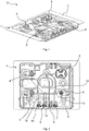
- the Fig. 1 shows a schematic perspective view of a hotplate, in particular a gas hotplate 1.
- the Fig. 2 shows a schematic plan view of the gas cooking point 1.
- the gas cooking point 1 has a trough-shaped base plate 2 in which gas burners 3 to 6 are at least partially accommodated.
- a gas control valve 7 to 10 is assigned to each gas burner 3 to 6.
- the gas control valves 7 to 10 are arranged on a main gas line 11.
- the gas control valves 7 to 8 are fluidically connected to the respective gas burners 3 to 6 via supply lines 12 to 15.
- the gas control valves 7 to 10 are set up to one of the main gas line 11 to the respective Gas burners 3 to 6 to regulate the fuel gas volume flow, in particular continuously.
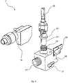
- the Fig. 3 shows an embodiment of the gas control valve 7 in a schematic perspective view.
- the gas control valves 8 to 10 are preferably constructed analogously to the gas control valve 7.
- the gas control valve 7 has a valve housing 16.
- the valve housing 16 comprises a gas outlet 17, via which fuel gas can be fed to the respective gas burner 3 to 6 with the aid of the corresponding supply line 12 to 15.
- the valve housing 16 also has a receiving section 18 which is set up to at least partially encompass the main gas line 11. That is to say, the valve housing 16 can at least partially receive the main gas line 11 in the receiving section 18.
- a gas inlet (not shown) is provided on the receiving section 18, through which fuel gas can be fed from the main gas line 11 to the valve housing 16.
- the gas control valve 7 can be clamped to the main gas line 11 with the aid of the receiving section 18.
- thermocouple receptacle 19 is provided on the valve housing 16.
- the thermocouple receptacle 19 is connected to a thermocouple assigned to the respective gas burner 3 to 6 in such a way that flame monitoring of the gas burner 3 to 6 is possible with the aid of the thermocouple. That is, when the gas flame goes out, the gas control valve 7 blocks the flow of fuel gas to the respective gas burner 3 to 6, so that fuel gas no longer flows from the gas control valve 7 to the gas burner 3 to 6.
- An actuating shaft 20 protrudes from the top of the valve housing 16. For example, a rotary knob for actuating the same can be provided on the actuating shaft 20.
- the Fig. 4 and 5 each show the gas control valve 7 in a schematic perspective exploded view.
- the thermocouple receptacle 19 is preferably designed to be removable from the valve housing 16.
- a recess 21 is provided on the side of the valve housing 16.
- the recess 21 is fluidically connected to fuel gas channels provided in the valve housing 16.
- the recess 21 can be closed in a fluid-tight manner with the aid of a cover 22.
- a valve body 23 is rotatably received in the valve housing 16.
- the valve body 23 is tubular and has a circumferential shoulder 24.
- a spring device 25 is positioned between the shoulder 24 and the valve housing 16. The spring device 25 engages around the tubular valve body 23 at least in sections.
- the spring device 25 is preferably a compression spring. The spring device 25 biases the valve body 23 in such a way that it is pressed out of the valve housing 16 by the spring device 25.
- an actuating slot 26 is provided on the valve body 23, into which a corresponding engagement section of the actuating shaft 20 engages in a form-fitting manner.
- the Fig. 6 shows the valve body 23 in a schematic perspective view.
- the valve body 23 has a gas flow opening 27.
- the gas throughflow opening 27 overlaps with the gas channels provided in the valve housing 16.
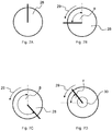
- the mode of operation of the gas control valve 7 is described below with reference to FIG Figures 7A-7D explained.
- the Figures 7A-7D each show an actuation button 28 coupled to the actuation shaft 20 of the gas control valve 7 in different positions.
- the Figure 7A shows the operating button 28 in a position in which the valve body 23 is in a closed position. In the closed position, the gas control valve 7 is closed and the gas flow opening 27 is completely covered by the valve housing 16.
- the valve body 23 can be rotated from the closed position in which the gas control valve 7 is closed in a predetermined direction of rotation 29 into an open position in which the gas control valve 7 is open.
- the predetermined direction of rotation 29 is oriented, for example, counterclockwise.
- An angle of rotation ⁇ between the closed position and the open position is 90 °, for example.
- the actuating button 28 can be rotated in the preferred direction of rotation 29 from the open position further into a small fire position.
- An angle ⁇ between the closed position and the small fire position is 210 °, for example.
- the gas control valve 7 is continuously adjustable. To spend of the gas control valve 7 from the small fire position to the closed position, the actuating button 28 is opposite to the predetermined direction of rotation 29 again in the Figure 7A shown closed position rotated.
- the valve body 23 can be rotated from the open position counter to the predetermined direction of rotation 29 into a so-called booster position or maximum fire position.
- An angle of rotation ⁇ between the open position and the booster position is 30 °, for example.
- a fuel gas volume flow flowing through the gas control valve 7 is greater than in the open position.
- the fuel gas volume flow in the booster position is constant and not continuously adjustable.
- valve body 23 can only be rotated into the booster position if it is pressed into the valve housing 16 against the spring force of the spring device 25.
- a booster gas channel can be provided in the valve housing 16, which fluidly connects the gas flow opening 27 of the valve body 23 directly to the gas outlet 17.
- the gas control valve 7 can furthermore have a time switch device 30, which is set up to automatically switch the valve body 23 away from the in the after a predetermined time interval Figure 7D Booster setting shown in the Figure 7B open position shown.
- the predetermined time interval is 30 seconds, for example.
- a gas stove 31 ( Fig. 1 ) can have one or more gas control valves 7 to 10 as described above and / or such a gas cooking point 1.
Landscapes
- Engineering & Computer Science (AREA)
- General Engineering & Computer Science (AREA)
- Mechanical Engineering (AREA)
- Chemical & Material Sciences (AREA)
- Combustion & Propulsion (AREA)
- Food Science & Technology (AREA)
- Manufacturing & Machinery (AREA)
- Physics & Mathematics (AREA)
- General Physics & Mathematics (AREA)
- Automation & Control Theory (AREA)
- Feeding And Controlling Fuel (AREA)
- Lift Valve (AREA)
Claims (9)
- Soupape de régulation de gaz (7 - 10) pour un poste de cuisson (1), avec un carter de soupape (16) et un corps de soupape (23) logé dans le carter de soupape (16), dans laquelle le corps de soupape (23) peut tourner d'une position fermée dans laquelle la soupape de régulation de gaz (7 - 10) est fermée, selon un sens de rotation (29) préalablement établi, vers une position ouverte dans laquelle la soupape de régulation de gaz (7 - 10) est ouverte, dans laquelle le corps de soupape (23) peut en outre tourner, selon le sens de rotation (29) préalablement établi, de la position ouverte vers une position de feux doux, dans laquelle un débit de gaz combustible pouvant traverser la soupape de régulation de gaz (7 - 10) peut en particulier être réglé en continu en tournant le corps de soupape (23) de la position ouverte vers la position à feux doux, dans laquelle le corps de soupape (23) peut tourner de la position ouverte à l'encontre du sens de rotation (29) préalablement établi vers une position boost, dans laquelle le débit du gaz combustible dans la position boost est supérieur à celui dans la position ouverte, dans laquelle le débit de gaz combustible dans la position boost est constant et dans lequel la position boost est disposée, vu à l'encontre du sens de rotation (29) préalablement établi, entre la position ouverte et la position fermée.
- Soupape de régulation de gaz selon la revendication 1, caractérisée par un dispositif interrupteur horaire (30) aménagé afin de tourner de façon autonome le corps de soupape (23) de la position boost vers la position ouverte après l'écoulement d'un intervalle de temps préalablement établi.
- Soupape de régulation de gaz selon la revendication 1 ou 2, caractérisée en ce que le corps de soupape (23) peut être inséré dans la carcasse de soupape pour la rotation de la position ouverte vers la position boost.
- Soupape de régulation de gaz selon la revendication 3, caractérisée par un dispositif élastique (25), dans laquelle le corps de soupape (23) peut être inséré dans le carter de soupape (16) à l'encontre d'une force de ressort du dispositif élastique (25).
- Soupape de régulation de gaz selon la revendication 3 ou 4, caractérisée en ce que le corps de soupape (23) peut être logé dans le dispositif élastique (25).
- Soupape de régulation de gaz selon l'une des revendications 1 à 5, caractérisée en ce que le carter de soupape (16) peut être attaché à une conduite principale de gaz (11) du poste de cuisson (1).
- Soupape de régulation de gaz selon l'une des revendications 1 à 6, dans laquelle le corps de soupape (23) est tubulaire.
- Poste de cuisson (1) avec une soupape de régulation de gaz (7 - 10) selon l'une des revendications 1 à 7.
- Cuisinière à gaz (31) avec une soupape de régulation de gaz (7 - 10) selon l'une des revendications 1 à 7 et/ou un poste de cuisson (1) selon la revendication 8.
Applications Claiming Priority (2)
| Application Number | Priority Date | Filing Date | Title |
|---|---|---|---|
| ES201430797A ES2552586B1 (es) | 2014-05-28 | 2014-05-28 | Válvula reguladora de gas, punto de cocción, y cocina de gas |
| PCT/IB2015/053593 WO2015181669A2 (fr) | 2014-05-28 | 2015-05-15 | Soupape de régulation de gaz, table de cuisson et cuisinière à gaz |
Publications (2)
| Publication Number | Publication Date |
|---|---|
| EP3149406A2 EP3149406A2 (fr) | 2017-04-05 |
| EP3149406B1 true EP3149406B1 (fr) | 2021-02-03 |
Family
ID=54366476
Family Applications (1)
| Application Number | Title | Priority Date | Filing Date |
|---|---|---|---|
| EP15788476.8A Active EP3149406B1 (fr) | 2014-05-28 | 2015-05-15 | Soupape de régulation de gaz, table de cuisson et cuisinière à gaz |
Country Status (5)
| Country | Link |
|---|---|
| US (1) | US10634360B2 (fr) |
| EP (1) | EP3149406B1 (fr) |
| CN (1) | CN106461095B (fr) |
| ES (2) | ES2552586B1 (fr) |
| WO (1) | WO2015181669A2 (fr) |
Families Citing this family (4)
| Publication number | Priority date | Publication date | Assignee | Title |
|---|---|---|---|---|
| IT201600131202A1 (it) * | 2016-12-27 | 2018-06-27 | Sabaf Spa | Rubinetto per bruciatore a gas |
| DE102017119032A1 (de) | 2017-08-21 | 2019-02-21 | Saeta Gmbh & Co. Kg | Verfahren und Vorrichtung zum Aufbringen einer Dichtungsmasse auf den Boden und die Innenseite einer ringförmigen Wand eines Deckels für Behälter |
| ES2776073B2 (es) | 2019-01-28 | 2021-11-17 | Llana Enrique Gonzalez | Valvula mecanica para fluidos. |
| EP3719399A1 (fr) * | 2019-04-02 | 2020-10-07 | BSH Hausgeräte GmbH | Soupape à gaz et cuisinière à gaz |
Citations (1)
| Publication number | Priority date | Publication date | Assignee | Title |
|---|---|---|---|---|
| JP2014081108A (ja) * | 2012-10-15 | 2014-05-08 | Mikuni Corp | ガス制御弁およびこれに用いるディスク部品 |
Family Cites Families (17)
| Publication number | Priority date | Publication date | Assignee | Title |
|---|---|---|---|---|
| US3442448A (en) * | 1965-02-12 | 1969-05-06 | Robertshaw Controls Co | Cooking and apparatus and methods |
| US3404673A (en) * | 1967-05-04 | 1968-10-08 | Tappan Co | Stove with waist-high broiler |
| DE2941543C2 (de) | 1979-10-13 | 1983-05-05 | Paul Isphording Metallwerke GmbH & Co KG, 5952 Attendorn | Vorrichtung zur Steuerung der Gaszufuhr |
| JPS59180208A (ja) * | 1983-03-29 | 1984-10-13 | Toyotomi Kogyo Co Ltd | 石油燃焼器の安全装置 |
| CN2406182Y (zh) * | 1999-11-22 | 2000-11-15 | 上海林内有限公司 | 用于燃气热水器中冬夏燃烧转换控制装置 |
| JP3819325B2 (ja) * | 2002-06-10 | 2006-09-06 | リンナイ株式会社 | ガス制御装置 |
| JP2004012064A (ja) * | 2002-06-10 | 2004-01-15 | Rinnai Corp | ガス制御装置 |
| AU2003264779A1 (en) | 2002-10-25 | 2004-05-13 | Pebble Bed Modular Reactor (Proprietary) Limited | Flow control device |
| ES1059642Y (es) * | 2005-02-10 | 2005-09-01 | Fagor S Coop | Valvula rotatoria montada en un aparato de coccion multi-gas |
| BRPI0614791A2 (pt) | 2005-08-16 | 2011-04-12 | Bsh Bosch Siemens Hausgeraete | dispositivo para aumentar potência por um tempo limitado |
| CN2864407Y (zh) * | 2005-11-30 | 2007-01-31 | 赖火成 | 定时自动关闭燃气的燃气炉 |
| ITVE20070031A1 (it) * | 2007-05-17 | 2008-11-18 | Defendi Italy Srl | Rubinetto gas con sicurezza per bruciatore dual. |
| DE102010030944A1 (de) | 2010-07-05 | 2012-01-05 | E.G.O. Elektro-Gerätebau GmbH | Verfahren zum Betrieb eines Gasbackofens und Gasbackofen |
| CN201903087U (zh) * | 2010-12-22 | 2011-07-20 | 桂林市淦隆环保科技有限公司 | 火力无级可调液体燃料火锅灶 |
| JP5441992B2 (ja) * | 2011-11-25 | 2014-03-12 | リンナイ株式会社 | 火力調節装置 |
| CN202392211U (zh) * | 2011-11-30 | 2012-08-22 | 美的集团有限公司 | 燃气灶具的调节阀组件 |
| CN204329084U (zh) * | 2014-11-27 | 2015-05-13 | 谢启标 | 一种可连续调节火力大小的燃气灶具 |
-
2014
- 2014-05-28 ES ES201430797A patent/ES2552586B1/es not_active Revoked
-
2015
- 2015-05-15 WO PCT/IB2015/053593 patent/WO2015181669A2/fr not_active Ceased
- 2015-05-15 CN CN201580028317.9A patent/CN106461095B/zh active Active
- 2015-05-15 EP EP15788476.8A patent/EP3149406B1/fr active Active
- 2015-05-15 ES ES15788476T patent/ES2875923T3/es active Active
- 2015-05-15 US US15/309,807 patent/US10634360B2/en not_active Expired - Fee Related
Patent Citations (1)
| Publication number | Priority date | Publication date | Assignee | Title |
|---|---|---|---|---|
| JP2014081108A (ja) * | 2012-10-15 | 2014-05-08 | Mikuni Corp | ガス制御弁およびこれに用いるディスク部品 |
Also Published As
| Publication number | Publication date |
|---|---|
| WO2015181669A2 (fr) | 2015-12-03 |
| WO2015181669A3 (fr) | 2016-03-17 |
| ES2875923T3 (es) | 2021-11-11 |
| US10634360B2 (en) | 2020-04-28 |
| CN106461095B (zh) | 2020-02-14 |
| US20170167732A1 (en) | 2017-06-15 |
| ES2552586A1 (es) | 2015-11-30 |
| ES2552586B1 (es) | 2016-09-14 |
| EP3149406A2 (fr) | 2017-04-05 |
| CN106461095A (zh) | 2017-02-22 |
Similar Documents
| Publication | Publication Date | Title |
|---|---|---|
| EP2946041B1 (fr) | Robinet sanitaire | |
| EP2387740B1 (fr) | Dispositif mitigeur à régulation électronique pour l'eau de distribution | |
| EP3149406B1 (fr) | Soupape de régulation de gaz, table de cuisson et cuisinière à gaz | |
| WO2016131500A1 (fr) | Ustensile de cuisine et procédé de fonctionnement dudit ustensile de cuisine | |
| DE60008954T2 (de) | Sicherheitgasventilanordnung für einen Kochherd | |
| EP3044512A1 (fr) | Ensemble brûleur pour plan de cuisson fonctionnant au gaz, plan de cuisson fonctionnant au gaz et gazinière | |
| DE4423240C1 (de) | Thermostatventil | |
| EP3055618B1 (fr) | Robinet de gaz, plaque de cuisson et appareil de cuisson à gaz | |
| DE102016109412B4 (de) | Stelleinrichtung | |
| DE2941543C2 (de) | Vorrichtung zur Steuerung der Gaszufuhr | |
| EP3146269B1 (fr) | Montage, plaque de cuisson et appareil de cuisson à gaz | |
| DE102013218014B4 (de) | Gasventileinrichtung und Gasgerät mit einer Gasventileinrichtung | |
| DE102013004745B4 (de) | Gasregelarmatur | |
| DE2312305C2 (de) | Einrichtung zum Beeinflussen der Leistung eines gasbeheizten Durchlauf-Wassererhitzers | |
| EP3112540A1 (fr) | Partie superieure de soupape | |
| EP3292251A1 (fr) | Unité anti-ébullition | |
| EP3220046B1 (fr) | Vanne de gaz et appareil de cuisson | |
| DE102014216363A1 (de) | Gasventileinrichtung für ein Gasgerät und Gasgerät | |
| AT224862B (de) | Thermoelektrisch gesteuerte, kombinierte Gasabsperreinheit und Zündflammensicherung | |
| DE350570C (de) | Vorrichtung zur Regelung des Luftzutritts zur Mischkammer von Bunsenbrennern | |
| DE707636C (de) | Gashahn | |
| DE622157C (de) | Gashahn | |
| CH395879A (de) | Mischbatterie | |
| DE2153687A1 (de) | Gasbeheizter durchlauf-wassererhitzer | |
| DE1454354A1 (de) | Gasreguliereinrichtung,insbesondere an Kochherden |
Legal Events
| Date | Code | Title | Description |
|---|---|---|---|
| STAA | Information on the status of an ep patent application or granted ep patent |
Free format text: STATUS: THE INTERNATIONAL PUBLICATION HAS BEEN MADE |
|
| PUAI | Public reference made under article 153(3) epc to a published international application that has entered the european phase |
Free format text: ORIGINAL CODE: 0009012 |
|
| STAA | Information on the status of an ep patent application or granted ep patent |
Free format text: STATUS: REQUEST FOR EXAMINATION WAS MADE |
|
| 17P | Request for examination filed |
Effective date: 20170102 |
|
| AK | Designated contracting states |
Kind code of ref document: A2 Designated state(s): AL AT BE BG CH CY CZ DE DK EE ES FI FR GB GR HR HU IE IS IT LI LT LU LV MC MK MT NL NO PL PT RO RS SE SI SK SM TR |
|
| AX | Request for extension of the european patent |
Extension state: BA ME |
|
| DAV | Request for validation of the european patent (deleted) | ||
| DAX | Request for extension of the european patent (deleted) | ||
| STAA | Information on the status of an ep patent application or granted ep patent |
Free format text: STATUS: EXAMINATION IS IN PROGRESS |
|
| 17Q | First examination report despatched |
Effective date: 20190215 |
|
| GRAP | Despatch of communication of intention to grant a patent |
Free format text: ORIGINAL CODE: EPIDOSNIGR1 |
|
| STAA | Information on the status of an ep patent application or granted ep patent |
Free format text: STATUS: GRANT OF PATENT IS INTENDED |
|
| INTG | Intention to grant announced |
Effective date: 20200925 |
|
| GRAS | Grant fee paid |
Free format text: ORIGINAL CODE: EPIDOSNIGR3 |
|
| GRAA | (expected) grant |
Free format text: ORIGINAL CODE: 0009210 |
|
| STAA | Information on the status of an ep patent application or granted ep patent |
Free format text: STATUS: THE PATENT HAS BEEN GRANTED |
|
| AK | Designated contracting states |
Kind code of ref document: B1 Designated state(s): AL AT BE BG CH CY CZ DE DK EE ES FI FR GB GR HR HU IE IS IT LI LT LU LV MC MK MT NL NO PL PT RO RS SE SI SK SM TR |
|
| REG | Reference to a national code |
Ref country code: GB Ref legal event code: FG4D Free format text: NOT ENGLISH |
|
| REG | Reference to a national code |
Ref country code: AT Ref legal event code: REF Ref document number: 1359785 Country of ref document: AT Kind code of ref document: T Effective date: 20210215 Ref country code: CH Ref legal event code: EP |
|
| REG | Reference to a national code |
Ref country code: DE Ref legal event code: R096 Ref document number: 502015014223 Country of ref document: DE |
|
| REG | Reference to a national code |
Ref country code: IE Ref legal event code: FG4D Free format text: LANGUAGE OF EP DOCUMENT: GERMAN |
|
| REG | Reference to a national code |
Ref country code: NL Ref legal event code: MP Effective date: 20210203 |
|
| REG | Reference to a national code |
Ref country code: LT Ref legal event code: MG9D |
|
| PG25 | Lapsed in a contracting state [announced via postgrant information from national office to epo] |
Ref country code: PT Free format text: LAPSE BECAUSE OF FAILURE TO SUBMIT A TRANSLATION OF THE DESCRIPTION OR TO PAY THE FEE WITHIN THE PRESCRIBED TIME-LIMIT Effective date: 20210604 Ref country code: LT Free format text: LAPSE BECAUSE OF FAILURE TO SUBMIT A TRANSLATION OF THE DESCRIPTION OR TO PAY THE FEE WITHIN THE PRESCRIBED TIME-LIMIT Effective date: 20210203 Ref country code: GR Free format text: LAPSE BECAUSE OF FAILURE TO SUBMIT A TRANSLATION OF THE DESCRIPTION OR TO PAY THE FEE WITHIN THE PRESCRIBED TIME-LIMIT Effective date: 20210504 Ref country code: HR Free format text: LAPSE BECAUSE OF FAILURE TO SUBMIT A TRANSLATION OF THE DESCRIPTION OR TO PAY THE FEE WITHIN THE PRESCRIBED TIME-LIMIT Effective date: 20210203 Ref country code: FI Free format text: LAPSE BECAUSE OF FAILURE TO SUBMIT A TRANSLATION OF THE DESCRIPTION OR TO PAY THE FEE WITHIN THE PRESCRIBED TIME-LIMIT Effective date: 20210203 Ref country code: NO Free format text: LAPSE BECAUSE OF FAILURE TO SUBMIT A TRANSLATION OF THE DESCRIPTION OR TO PAY THE FEE WITHIN THE PRESCRIBED TIME-LIMIT Effective date: 20210503 Ref country code: BG Free format text: LAPSE BECAUSE OF FAILURE TO SUBMIT A TRANSLATION OF THE DESCRIPTION OR TO PAY THE FEE WITHIN THE PRESCRIBED TIME-LIMIT Effective date: 20210503 |
|
| PG25 | Lapsed in a contracting state [announced via postgrant information from national office to epo] |
Ref country code: PL Free format text: LAPSE BECAUSE OF FAILURE TO SUBMIT A TRANSLATION OF THE DESCRIPTION OR TO PAY THE FEE WITHIN THE PRESCRIBED TIME-LIMIT Effective date: 20210203 Ref country code: LV Free format text: LAPSE BECAUSE OF FAILURE TO SUBMIT A TRANSLATION OF THE DESCRIPTION OR TO PAY THE FEE WITHIN THE PRESCRIBED TIME-LIMIT Effective date: 20210203 Ref country code: NL Free format text: LAPSE BECAUSE OF FAILURE TO SUBMIT A TRANSLATION OF THE DESCRIPTION OR TO PAY THE FEE WITHIN THE PRESCRIBED TIME-LIMIT Effective date: 20210203 Ref country code: RS Free format text: LAPSE BECAUSE OF FAILURE TO SUBMIT A TRANSLATION OF THE DESCRIPTION OR TO PAY THE FEE WITHIN THE PRESCRIBED TIME-LIMIT Effective date: 20210203 Ref country code: SE Free format text: LAPSE BECAUSE OF FAILURE TO SUBMIT A TRANSLATION OF THE DESCRIPTION OR TO PAY THE FEE WITHIN THE PRESCRIBED TIME-LIMIT Effective date: 20210203 |
|
| PG25 | Lapsed in a contracting state [announced via postgrant information from national office to epo] |
Ref country code: IS Free format text: LAPSE BECAUSE OF FAILURE TO SUBMIT A TRANSLATION OF THE DESCRIPTION OR TO PAY THE FEE WITHIN THE PRESCRIBED TIME-LIMIT Effective date: 20210603 |
|
| PG25 | Lapsed in a contracting state [announced via postgrant information from national office to epo] |
Ref country code: EE Free format text: LAPSE BECAUSE OF FAILURE TO SUBMIT A TRANSLATION OF THE DESCRIPTION OR TO PAY THE FEE WITHIN THE PRESCRIBED TIME-LIMIT Effective date: 20210203 Ref country code: SM Free format text: LAPSE BECAUSE OF FAILURE TO SUBMIT A TRANSLATION OF THE DESCRIPTION OR TO PAY THE FEE WITHIN THE PRESCRIBED TIME-LIMIT Effective date: 20210203 |
|
| REG | Reference to a national code |
Ref country code: DE Ref legal event code: R097 Ref document number: 502015014223 Country of ref document: DE |
|
| REG | Reference to a national code |
Ref country code: ES Ref legal event code: FG2A Ref document number: 2875923 Country of ref document: ES Kind code of ref document: T3 Effective date: 20211111 |
|
| PG25 | Lapsed in a contracting state [announced via postgrant information from national office to epo] |
Ref country code: DK Free format text: LAPSE BECAUSE OF FAILURE TO SUBMIT A TRANSLATION OF THE DESCRIPTION OR TO PAY THE FEE WITHIN THE PRESCRIBED TIME-LIMIT Effective date: 20210203 Ref country code: SK Free format text: LAPSE BECAUSE OF FAILURE TO SUBMIT A TRANSLATION OF THE DESCRIPTION OR TO PAY THE FEE WITHIN THE PRESCRIBED TIME-LIMIT Effective date: 20210203 Ref country code: RO Free format text: LAPSE BECAUSE OF FAILURE TO SUBMIT A TRANSLATION OF THE DESCRIPTION OR TO PAY THE FEE WITHIN THE PRESCRIBED TIME-LIMIT Effective date: 20210203 |
|
| REG | Reference to a national code |
Ref country code: DE Ref legal event code: R119 Ref document number: 502015014223 Country of ref document: DE |
|
| PLBE | No opposition filed within time limit |
Free format text: ORIGINAL CODE: 0009261 |
|
| STAA | Information on the status of an ep patent application or granted ep patent |
Free format text: STATUS: NO OPPOSITION FILED WITHIN TIME LIMIT |
|
| REG | Reference to a national code |
Ref country code: CH Ref legal event code: PL |
|
| 26N | No opposition filed |
Effective date: 20211104 |
|
| GBPC | Gb: european patent ceased through non-payment of renewal fee |
Effective date: 20210515 |
|
| PG25 | Lapsed in a contracting state [announced via postgrant information from national office to epo] |
Ref country code: AL Free format text: LAPSE BECAUSE OF FAILURE TO SUBMIT A TRANSLATION OF THE DESCRIPTION OR TO PAY THE FEE WITHIN THE PRESCRIBED TIME-LIMIT Effective date: 20210203 Ref country code: CH Free format text: LAPSE BECAUSE OF NON-PAYMENT OF DUE FEES Effective date: 20210531 Ref country code: LI Free format text: LAPSE BECAUSE OF NON-PAYMENT OF DUE FEES Effective date: 20210531 Ref country code: LU Free format text: LAPSE BECAUSE OF NON-PAYMENT OF DUE FEES Effective date: 20210515 Ref country code: MC Free format text: LAPSE BECAUSE OF FAILURE TO SUBMIT A TRANSLATION OF THE DESCRIPTION OR TO PAY THE FEE WITHIN THE PRESCRIBED TIME-LIMIT Effective date: 20210203 |
|
| REG | Reference to a national code |
Ref country code: BE Ref legal event code: MM Effective date: 20210531 |
|
| PG25 | Lapsed in a contracting state [announced via postgrant information from national office to epo] |
Ref country code: SI Free format text: LAPSE BECAUSE OF FAILURE TO SUBMIT A TRANSLATION OF THE DESCRIPTION OR TO PAY THE FEE WITHIN THE PRESCRIBED TIME-LIMIT Effective date: 20210203 |
|
| PG25 | Lapsed in a contracting state [announced via postgrant information from national office to epo] |
Ref country code: IE Free format text: LAPSE BECAUSE OF NON-PAYMENT OF DUE FEES Effective date: 20210515 Ref country code: GB Free format text: LAPSE BECAUSE OF NON-PAYMENT OF DUE FEES Effective date: 20210515 Ref country code: DE Free format text: LAPSE BECAUSE OF NON-PAYMENT OF DUE FEES Effective date: 20211201 |
|
| PG25 | Lapsed in a contracting state [announced via postgrant information from national office to epo] |
Ref country code: IS Free format text: LAPSE BECAUSE OF FAILURE TO SUBMIT A TRANSLATION OF THE DESCRIPTION OR TO PAY THE FEE WITHIN THE PRESCRIBED TIME-LIMIT Effective date: 20210603 Ref country code: FR Free format text: LAPSE BECAUSE OF NON-PAYMENT OF DUE FEES Effective date: 20210531 |
|
| REG | Reference to a national code |
Ref country code: AT Ref legal event code: MM01 Ref document number: 1359785 Country of ref document: AT Kind code of ref document: T Effective date: 20210515 |
|
| PG25 | Lapsed in a contracting state [announced via postgrant information from national office to epo] |
Ref country code: BE Free format text: LAPSE BECAUSE OF NON-PAYMENT OF DUE FEES Effective date: 20210531 |
|
| PG25 | Lapsed in a contracting state [announced via postgrant information from national office to epo] |
Ref country code: AT Free format text: LAPSE BECAUSE OF NON-PAYMENT OF DUE FEES Effective date: 20210515 |
|
| PG25 | Lapsed in a contracting state [announced via postgrant information from national office to epo] |
Ref country code: HU Free format text: LAPSE BECAUSE OF FAILURE TO SUBMIT A TRANSLATION OF THE DESCRIPTION OR TO PAY THE FEE WITHIN THE PRESCRIBED TIME-LIMIT; INVALID AB INITIO Effective date: 20150515 |
|
| PG25 | Lapsed in a contracting state [announced via postgrant information from national office to epo] |
Ref country code: CY Free format text: LAPSE BECAUSE OF FAILURE TO SUBMIT A TRANSLATION OF THE DESCRIPTION OR TO PAY THE FEE WITHIN THE PRESCRIBED TIME-LIMIT Effective date: 20210203 |
|
| PGFP | Annual fee paid to national office [announced via postgrant information from national office to epo] |
Ref country code: ES Payment date: 20230621 Year of fee payment: 9 Ref country code: CZ Payment date: 20230504 Year of fee payment: 9 |
|
| PG25 | Lapsed in a contracting state [announced via postgrant information from national office to epo] |
Ref country code: MK Free format text: LAPSE BECAUSE OF FAILURE TO SUBMIT A TRANSLATION OF THE DESCRIPTION OR TO PAY THE FEE WITHIN THE PRESCRIBED TIME-LIMIT Effective date: 20210203 |
|
| PG25 | Lapsed in a contracting state [announced via postgrant information from national office to epo] |
Ref country code: MT Free format text: LAPSE BECAUSE OF FAILURE TO SUBMIT A TRANSLATION OF THE DESCRIPTION OR TO PAY THE FEE WITHIN THE PRESCRIBED TIME-LIMIT Effective date: 20210203 |
|
| PG25 | Lapsed in a contracting state [announced via postgrant information from national office to epo] |
Ref country code: CZ Free format text: LAPSE BECAUSE OF NON-PAYMENT OF DUE FEES Effective date: 20240515 |
|
| PG25 | Lapsed in a contracting state [announced via postgrant information from national office to epo] |
Ref country code: CZ Free format text: LAPSE BECAUSE OF NON-PAYMENT OF DUE FEES Effective date: 20240515 |
|
| REG | Reference to a national code |
Ref country code: ES Ref legal event code: FD2A Effective date: 20250630 |
|
| PG25 | Lapsed in a contracting state [announced via postgrant information from national office to epo] |
Ref country code: ES Free format text: LAPSE BECAUSE OF NON-PAYMENT OF DUE FEES Effective date: 20240516 |
|
| PGFP | Annual fee paid to national office [announced via postgrant information from national office to epo] |
Ref country code: IT Payment date: 20250530 Year of fee payment: 11 |
|
| PGFP | Annual fee paid to national office [announced via postgrant information from national office to epo] |
Ref country code: TR Payment date: 20250507 Year of fee payment: 11 |