EP3149434B1 - Analysegerät zur wasser- und abwasseranalyse - Google Patents
Analysegerät zur wasser- und abwasseranalyse Download PDFInfo
- Publication number
- EP3149434B1 EP3149434B1 EP15737972.8A EP15737972A EP3149434B1 EP 3149434 B1 EP3149434 B1 EP 3149434B1 EP 15737972 A EP15737972 A EP 15737972A EP 3149434 B1 EP3149434 B1 EP 3149434B1
- Authority
- EP
- European Patent Office
- Prior art keywords
- housing
- component
- opening
- carriage
- insert
- Prior art date
- Legal status (The legal status is an assumption and is not a legal conclusion. Google has not performed a legal analysis and makes no representation as to the accuracy of the status listed.)
- Active
Links
Images

Classifications
-
- G—PHYSICS
- G01—MEASURING; TESTING
- G01N—INVESTIGATING OR ANALYSING MATERIALS BY DETERMINING THEIR CHEMICAL OR PHYSICAL PROPERTIES
- G01N33/00—Investigating or analysing materials by specific methods not covered by groups G01N1/00 - G01N31/00
- G01N33/18—Water
- G01N33/1806—Biological oxygen demand [BOD] or chemical oxygen demand [COD]
-
- G—PHYSICS
- G01—MEASURING; TESTING
- G01N—INVESTIGATING OR ANALYSING MATERIALS BY DETERMINING THEIR CHEMICAL OR PHYSICAL PROPERTIES
- G01N25/00—Investigating or analyzing materials by the use of thermal means
-
- G—PHYSICS
- G01—MEASURING; TESTING
- G01N—INVESTIGATING OR ANALYSING MATERIALS BY DETERMINING THEIR CHEMICAL OR PHYSICAL PROPERTIES
- G01N33/00—Investigating or analysing materials by specific methods not covered by groups G01N1/00 - G01N31/00
- G01N33/18—Water
Definitions
- the invention relates to an analyzer, in particular for water and wastewater analysis, with a device housing which accommodates device components.
- Such analyzers are typically provided with closed housings that need to be partially disassembled for maintenance or for not too frequent testing or adjustment operations on the instrument components.
- the housing is sometimes designed as a cabinet, so provided with a front-engaging door, which may be designed for the purpose of a first visual inspection of the device components as a glass door.
- the invention is based on the object of specifying an improved with regard to its practical handling analysis device of the generic type.
- the invention initially includes the idea to provide on a housing surface of the device housing a tool-free opening to be closed and to be closed, which is configured so that test or maintenance requiring device components can be brought to the outside of the device.
- a component carriage or insert is provided for this purpose, which carries the relevant device components and is configured and arranged together with them such that it can be transported through the opening at least partially to the outside. Under a slide in this case a slidable in a sliding part is understood, while under a use in another way (such as by manual lifting or by pivoting) through the opening transportable part is understood.
- a hinged door or flap hinged to a housing edge is provided for closing the opening.
- a door is not designed as the entire device front engaging part.
- a closure plate for closing the opening with retracted component carriage or inserted component insert is attached to the leading edge of the component carriage or insert.
- the revolving door or flap or closure plate for Brmögüchung an air exchange and / or for heat dissipation from the housing interior is perforated.
- the opening in the device housing occupies only a portion of the housing front, in particular between 25 and 75% and more particularly between 40 and 60%, and the component slide or insert configured thereover occupies a corresponding proportion of the volume of the device housing , This ensures that operating and / or display elements can be attached to the remaining part of the front of the housing.
- the opening in the device housing is provided in a side surface thereof, such that the housing front is substantially completely usable for operating and / or display elements.
- the analyzer 1 comprises a thermal reaction vessel or an oven EB into which a water sample can be injected by means of a syringe MM and in which this sample is thermally digested.
- the furnace is fed via a check valve RM1, a carrier gas stream, which is composed of air and nitrogen.
- the carrier gas flow is controlled by means of an air pressure regulator KH1, a nitrogen pressure regulator KH2, an air flow regulator KH4 and a nitrogen continuous flow regulator KH5 and filtered by means of a first and second fine filter HQ1, HQ2 on the input side of the furnace.
- the gas stream On the output side of the furnace, the gas stream first passes into a condensate vessel CM1, and the non-condensed fraction then passes through a quartz wool filter HQ3 and an acid trap HS1 before it reaches the oxygen detector B1, which finally supplies an (electrical) measured value to further device components for signal processing , storage and display outputs.
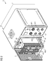
- Fig. 2 shows the analyzer 1 in a perspective view in a state in which the device housing 1 'are partially open and a part of the device components is pulled out of the housing.
- the device housing has essentially the shape of a square prism, and in the front of the device 1A 'is an opening 1B' is provided, which is closed by a hinged on the left side edge of the device front, perforated door 3.
- the device housing 1 'with the door 3 is closed.
- a control panel 1C' On the right side of the front panel 1A 'is a control panel 1C', on which a plurality of control and display elements are arranged, including a temperature display / control TC and the air pressure or nitrogen pressure adjustment regulators KH1 and KH2 and the associated display elements BP1 and BP2.
- a temperature display / control TC On the upper side of the device 1D 'there is an injection port 7 whose construction and dimensions correspond to those of the Fig. 1 syringe MM are adapted and communicates inside the device with a corresponding injection valve EB1 of the furnace EB when the furnace is in its normal position of use within the device housing.
Landscapes
- Life Sciences & Earth Sciences (AREA)
- Health & Medical Sciences (AREA)
- Chemical & Material Sciences (AREA)
- Engineering & Computer Science (AREA)
- Immunology (AREA)
- Pathology (AREA)
- Physics & Mathematics (AREA)
- Analytical Chemistry (AREA)
- Biochemistry (AREA)
- General Health & Medical Sciences (AREA)
- General Physics & Mathematics (AREA)
- Medicinal Chemistry (AREA)
- Food Science & Technology (AREA)
- Biodiversity & Conservation Biology (AREA)
- Biomedical Technology (AREA)
- Emergency Medicine (AREA)
- Molecular Biology (AREA)
- Automatic Analysis And Handling Materials Therefor (AREA)
- Investigating Or Analyzing Non-Biological Materials By The Use Of Chemical Means (AREA)
- Sampling And Sample Adjustment (AREA)
Description
- Die Erfindung betrifft ein Analysegerät, insbesondere zur Wasser- und Abwasseranalyse, mit einem Gerätegehäuse, welches Gerätekomponenten aufnimmt.
- Derartige Analysegeräte sind typischerweise mit geschlossenen Gehäusen versehen, die für Wartungsarbeiten oder für nicht allzu häufig vorkommende Prüf- bzw. Einstellvorgänge an den Gerätekomponenten partiell demontiert werden müssen. Bei Geräten, die eine relativ häufige Prüfung, Einstellung oder Wartung bestimmter Gerätekomponenten erfordern, ist das Gehäuse mitunter auch schrankartig ausgeführt, also mit einer die Vorderfront einnehmenden Tür versehen, die zum Zwecke einer ersten Sichtkontrolle der Gerätekomponenten auch als Glastür ausgeführt sein kann.
- Der Erfindung liegt die Aufgabe zu Grunde, ein hinsichtlich seiner praktischen Handhabung verbessertes Analysegerät der gattungsgemäßen Art anzugeben.
- Diese Aufgabe wird nach einem ersten Aspekt der Erfindung gelöst durch ein Analysegerät mit den Merkmalen des Anspruchs 1. Zweckmäßige Fortbildungen des Erfindungsgedankens sind Gegenstand der abhängigen Ansprüche.
- Die Erfindung schließt zunächst den Gedanken ein, an einer Gehäusefläche des Gerätegehäuses eine werkzeugfrei zu öffnende und zu verschließende Öffnung vorzusehen, die so konfiguriert ist, dass prüf- bzw. wartungsbedürftige Gerätekomponenten hierdurch nach außerhalb des Gerätes gebracht werden können. Gemäß einem zweiten Gedanken ist hierzu ein Komponentenschlitten oder -einsatz vorgesehen, der die relevanten Gerätekomponenten trägt und mit diesen zusammen derart konfiguriert und angeordnet ist, dass er durch die Öffnung mindestens teilweise nach außen transportiert werden kann. Unter einem Schlitten wird hierbei ein in einer Gleitführung verschiebliches Teil verstanden, während unter einem Einsatz ein auf andere Weise (etwa durch manuelles Herausheben oder auch durch Schwenken) durch die Öffnung transportierbares Teil verstanden wird.
- Gemäß einer ersten Ausführung der Erfindung ist zum Verschließen der Öffnung eine an einer Gehäusekante angeschlagene Drehtür oder Klappe vorgesehen. Im Unterschied zu bekannten Analysegeräten ist eine solche Tür aber nicht als die gesamte Gerätefront einnehmendes Teil gestaltet. In einer alternativen Ausführung ist an der Vorderkante des Komponentenschlittens oder -einsatzes eine Verschlussplatte zum Verschließen der Öffnung bei eingezogenem Komponentenschlitten oder eingefügtem Komponenteneinsatz angebracht.
- In einer Ausgestaltung beider Ausführungen ist die Drehtür oder Klappe oder Verschlussplatte zur Brmögüchung eines Luftaustauschs und/oder zur Wärmeabführung aus dem Gehäuseinneren perforiert.
- Gemäß der Erfindung nimmt die Öffnung im Gerätegehäuse nur einen Teil der Gehäusefront, insbesondere zwischen 25 und 75 % und noch spezieller zwischen 40 und 60 %, ein, und der in Anpassung hieran konfigurierte Komponentenschlitten oder -einsatz nimmt einen entsprechenden Anteil des Volumens des Gerätegehäuses ein. Dies gewährleistet, dass am verbleibenden Teil der Gehäusefront Bedien- und/oder Anzeigeelemente angebracht sein können. In einer alternativen Ausgestaltung ist die Öffnung im Gerätegehäuse in einer Seitenfläche desselben vorgesehen, derart, dass die Gehäusefront im Wesentlichen vollständig für Bedien- und/oder Anzeigeelemente nutzbar ist.
- Vorteile und Zweckmäßigkeiten der Erfindung ergeben sich im Übrigen aus der nachfolgenden kurzen Beschreibung eines Ausführungsbeispiels anhand der Figuren. Von diesen zeigen:
-
Fig. 1 eine schematische Darstellung wesentlicher Gerätekomponenten eines Analysegerätes gemäß einem Ausführungsbeispiel und -
Fig. 2 eine perspektivische Darstellung jenes Analysegerätes. -
Fig. 1 und2 zeigen schematisch wesentliche Teile eines Analysegerätes 1 zur Bestimmung des chemischen Sauerstoffbedarfs (CSB oder COD = chemical oxygen demand) von Wasser oder Abwasser. Der grundsätzliche Aufbau derartiger Geräte und deren Funktionsweise sind dem Fachmann bekannt und werden daher hier nicht näher beschrieben, zumal es hierauf zum Verständnis der vorliegenden Erfindung nicht ankommt. - Das Analysegerät 1 umfasst ein thermisches Reaktionsgefäß bzw. einen Ofen EB, in den mittels einer Injektionsspritze MM eine Wasserprobe eingespritzt werden kann und in dem diese Probe thermisch aufgeschlossen wird. Dem Ofen wird über ein Rückschlagventil RM1 ein Trägergasstrom zugeführt, welcher aus Luft und Stickstoff zusammengesetzt wird. Der Trägergasstrom wird mittels eines Luft-Druckreglers KH1, eines Stickstoff-Druckreglers KH2, eines Luft-Durchflussreglers KH4 und eines Stickstoff-Durcbfäussregters KH5 gesteuert und mittels eines ersten und zweiten Feinfilters HQ1, HQ2 eingangsseitig des Ofens gefiltert. Eingangsseitig des Ofens sind auch eine Luft-Druckanzeige BP1 und eine Stickstoff-Druckanzeige BP2 vorgesehen.
- Ausgangsseitig des Ofens gelangt der Gasstrom zunächst in ein Kondensatgefäß CM1, und der nicht kondensierte Anteil durchläuft anschließend ein Quarzwollefilter HQ3 und eine Säurefalle HS1, bevor er zum Sauerstoffdetektor B1 gelangt, welcher schließlich einen (elektrischen) Messwert an (nicht dargestellte) weitere Gerätekomponenten zur Signalverarbeitung, -speicherung und -darstellung ausgibt.
-
Fig. 2 zeigt das Analysegerät 1 in perspektivischer Darstellung in einem Zustand, in dem das Gerätegehäuse 1' teilweise geöffnet sind und ein Teil der Gerätekomponenten aus dem Gehäuse herausgezogen ist. Das Gerätegehäuse hat im Wesentlichen die Gestalt eines quadratischen Prismas, und in der Gerätefront 1A' ist eine Öffnung 1B' vorgesehen, die durch eine an der linken Seitenkante der Gerätefront angeschlagene, perforierte Tür 3 zu verschließen ist. - Ein in seinen Abmessungen an die Öffnung 1B' angepasster Schlitten 5, auf dem der Ofen EB, das Kondensatgefäß CM1, das Quarzwollefüter HQ3 und die Säurefalle HS1 angeordnet sind, ist so weit aus dem Gehäuse herausziehbar, dass die genannten Komponenten frei zugänglich werden. Im zurückgeschobenen Zustand des Schlittens 5 wird das Gerätegehäuse 1' mit der Tür 3 verschlossen.
- Auf der rechten Seite der Gerätefront 1A' befindet sich ein Bedienfeld 1C', auf dem mehrere Bedien- und Anzeigeelemente angeordnet sind, darunter eine Temperaturaszeige /-steuerung TC und die Einstellregler KH1 und KH2 für den Luft- bzw. Stickstoffdruck und die zugehörigen Anzeigeelemente BP1 und BP2. Auf der Geräteoberseite 1D' befindet sich ein Injektionsport 7, dessen Aufbau und Abmessungen an diejenigen der in
Fig. 1 gezeigten Injektionsspritze MM angepasst sind und der im Geräteinneren mit einem entsprechenden Einspritzventil EB1 des Ofens EB kommuniziert, wenn der Ofen sich in seiner normalen Gebrauchslage Innerhalb des Gerätegehäuses befindet. - Die Ausführung der Erfindung ist nicht auf dieses Beispiel beschränkt, sondern ebenso in einer Vielzahl von Abwandlungen möglich, die im Rahmen der folgenden Ansprüche liegen.
Claims (5)
- Analysegerät, insbesondere zur Wasser- und Abwasseranalyse, mit einem Gerätegehäuse, welches Gerätekomponenten aufnimmt und welches an der Gehäusefront eine werkzeugfrei öffen- und verschließbare Öffnung hat, und
einem Komponentenschlitten oder -einsatz, der einen Teil der Gerätekomponenten trägt und mit diesen zusammen derart konfiguriert und angeordnet ist, dass er durch die Öffnung mindestens teilweise nach außen transportiert werden kann, derart, dass die auf ihm angeordneten Gerätekomponenten leicht zugänglich werden,
wobei die Öffnung im Gerätegehäuse nur einen Teil der Gehäusefront, insbesondere zwischen 25 und 75 % und noch spezieller zwischen 40 und 60 %, einnimmt und der in Anpassung hieran konfigurierte Komponentenschlitten oder - einsatz einen entsprechenden Anteil des Volumens des Gerätegehäuses einnimmt, wobei am verbleibenden Teil der Gehäusefront Bedien- und/oder Anzeigeelemente vorgesehen sind; und wobei
auf der Geräteoberseite ein Injektionsport zum Einspritzen einer Flüssigkeit bei geschlossenem Gerätegehäuse vorgesehen ist, und mit einem im Analysegerät und auf dem Komponentenschlitten oder - einsatz untergebrachten Reaktionsgefäß zum thermischen Aufschluss des zu analysierenden Stoffes verbunden ist. - Analysegerät nach Anspruch 1, wobei zum Verschließen der Öffnung an der Gehäusefront eine an einer Gehäusekante angeschlagene Drehtür oder Klappe vorgesehen ist.
- Analysegerät nach Anspruch 1, wobei an der Vorderkante des Komponentenschlittens oder -einsatzes eine Verschlussplatte zum Verschließen der Öffnung bei eingezogenem Komponentenschlitten oder eingefügtem Komponenteneinsatz angebracht ist.
- Analysegerät nach Anspruch 2 oder 3, wobei die Drehtür oder Klappe oder Verschlussplatte zur Ermöglichung eines Luftaustauschs und/oder zur Wärmeabführung aus dem Gehäuseinneren perforiert ist.
- Analysegerät nach einem der vorangehenden Ansprüche, wobei der Injektionsport auf der Geräteoberseite oberhalb des Komponentenschlittens oder -einsatzes angeordnet ist.
Applications Claiming Priority (2)
| Application Number | Priority Date | Filing Date | Title |
|---|---|---|---|
| DE202014102443.3U DE202014102443U1 (de) | 2014-05-26 | 2014-05-26 | Analysegerät zur Wasser- und Abwasseranalyse |
| PCT/DE2015/200321 WO2015180721A2 (de) | 2014-05-26 | 2015-05-22 | Analysegerät zur wasser- und abwasseranalyse |
Publications (2)
| Publication Number | Publication Date |
|---|---|
| EP3149434A2 EP3149434A2 (de) | 2017-04-05 |
| EP3149434B1 true EP3149434B1 (de) | 2018-10-03 |
Family
ID=53372426
Family Applications (1)
| Application Number | Title | Priority Date | Filing Date |
|---|---|---|---|
| EP15737972.8A Active EP3149434B1 (de) | 2014-05-26 | 2015-05-22 | Analysegerät zur wasser- und abwasseranalyse |
Country Status (7)
| Country | Link |
|---|---|
| US (1) | US20170108482A1 (de) |
| EP (1) | EP3149434B1 (de) |
| KR (1) | KR101886554B1 (de) |
| CN (2) | CN106662562A (de) |
| BR (1) | BR112016027785B1 (de) |
| DE (1) | DE202014102443U1 (de) |
| WO (1) | WO2015180721A2 (de) |
Families Citing this family (1)
| Publication number | Priority date | Publication date | Assignee | Title |
|---|---|---|---|---|
| DE102018105611A1 (de) * | 2018-03-12 | 2019-09-12 | Lar Process Analysers Ag | Messanordnung und Messverfahren zur Bestimmung eines Inhaltsstoffes oder Qualitätsparameters von Wasser oder Abwasser |
Citations (2)
| Publication number | Priority date | Publication date | Assignee | Title |
|---|---|---|---|---|
| US3560156A (en) * | 1965-05-03 | 1971-02-02 | Dow Chemical Co | Determining the oxygen demand of combustible materials in aqueous dispersions |
| US5824886A (en) * | 1997-01-13 | 1998-10-20 | Tannas Co. | Foam tester |
Family Cites Families (13)
| Publication number | Priority date | Publication date | Assignee | Title |
|---|---|---|---|---|
| US3842679A (en) * | 1973-03-05 | 1974-10-22 | Varian Associates | Automatic sampler apparatus of modular construction |
| DE2908169A1 (de) * | 1979-03-02 | 1980-09-11 | Hartmann & Braun Ag | Analysengeraet fuer gase oder fluessigkeiten |
| DE19546952C2 (de) * | 1994-12-17 | 1999-06-17 | Horiba Ltd | Gasanalysator-Einschubanordnung |
| JPH09127099A (ja) * | 1995-11-06 | 1997-05-16 | Anima Denshi Kk | 水質監視装置 |
| JP2007093209A (ja) * | 2005-09-26 | 2007-04-12 | Shimadzu Corp | 水質分析計 |
| DE102009009438A1 (de) * | 2009-02-18 | 2010-08-26 | Conrad Electronic Se | Vorrichtung zum Messen der Luftfeuchtigkeit und/oder Lufttemperatur |
| NL1038266C2 (nl) * | 2010-09-27 | 2012-03-28 | Capilix B V | Meetsysteem en werkwijze voor het autonoom meten van een ion-concentratie met microchip capillaire elektroforese. |
| EP2466304A1 (de) * | 2010-12-16 | 2012-06-20 | Roche Diagnostics GmbH | Teststreifenvorrichtung |
| CN102426225B (zh) * | 2011-10-31 | 2015-01-07 | 青岛理工大学 | 一种研究地下水砷转化的实验装置及监测方法 |
| CN103105476A (zh) * | 2012-11-13 | 2013-05-15 | 青岛海颐天仪器有限公司 | 一种污水cod组分快速检测装置 |
| CN103257071A (zh) * | 2013-05-12 | 2013-08-21 | 南京师范大学 | 一种水质cod在线分析仪消解装置 |
| CN203415857U (zh) * | 2013-07-29 | 2014-01-29 | 溧阳市特种变压器电器设备有限公司 | 经济型电气柜 |
| CN203492280U (zh) * | 2013-09-03 | 2014-03-19 | 肖巍 | 分析仪的机柜及分析仪 |
-
2014
- 2014-05-26 DE DE202014102443.3U patent/DE202014102443U1/de not_active Expired - Lifetime
-
2015
- 2015-05-22 BR BR112016027785-6A patent/BR112016027785B1/pt active IP Right Grant
- 2015-05-22 CN CN201580027461.0A patent/CN106662562A/zh active Pending
- 2015-05-22 EP EP15737972.8A patent/EP3149434B1/de active Active
- 2015-05-22 KR KR1020167036208A patent/KR101886554B1/ko active Active
- 2015-05-22 WO PCT/DE2015/200321 patent/WO2015180721A2/de not_active Ceased
- 2015-05-22 US US15/314,271 patent/US20170108482A1/en not_active Abandoned
- 2015-05-22 CN CN202110095802.5A patent/CN112924638A/zh active Pending
Patent Citations (2)
| Publication number | Priority date | Publication date | Assignee | Title |
|---|---|---|---|---|
| US3560156A (en) * | 1965-05-03 | 1971-02-02 | Dow Chemical Co | Determining the oxygen demand of combustible materials in aqueous dispersions |
| US5824886A (en) * | 1997-01-13 | 1998-10-20 | Tannas Co. | Foam tester |
Non-Patent Citations (2)
| Title |
|---|
| SKALAR ANALYTICAL: "Formacs HT Total Organic Carbon Analyzer", 16 October 2012 (2012-10-16), XP054977854, Retrieved from the Internet <URL:https://www.youtube.com/watch?v=Ok6nBanIPVY> [retrieved on 20171103] * |
| SKALAR: "Total Organic Carbon and Total Nitrogen analyzers SERIES Formacs SERIES | Total Organic Carbon and Total Nitrogen analyzers https", 27 January 2013 (2013-01-27), XP055421675, Retrieved from the Internet <URL:https://web.archive.org/web/20130127231717/http://www.skalar.com:80/analyzers/total-organic-carbon-toc-and-total-nitrogen-tn-analyzers> [retrieved on 20171103] * |
Also Published As
| Publication number | Publication date |
|---|---|
| KR20170010842A (ko) | 2017-02-01 |
| BR112016027785A2 (de) | 2017-08-15 |
| WO2015180721A3 (de) | 2016-02-25 |
| US20170108482A1 (en) | 2017-04-20 |
| KR101886554B1 (ko) | 2018-08-07 |
| EP3149434A2 (de) | 2017-04-05 |
| WO2015180721A2 (de) | 2015-12-03 |
| CN106662562A (zh) | 2017-05-10 |
| DE202014102443U1 (de) | 2015-05-27 |
| BR112016027785B1 (pt) | 2022-05-10 |
| CN112924638A (zh) | 2021-06-08 |
Similar Documents
| Publication | Publication Date | Title |
|---|---|---|
| EP0179296B1 (de) | Vorrichtung zur Ermittlung der quantitativen Zusammensetzung von Gasen | |
| DE102014201076B3 (de) | Transportbehälter für einen NMR MAS-Rotor | |
| EP3374012B1 (de) | Beatmungsgerät | |
| EP3287780B1 (de) | Analyseanordnung zur wasser- und abwasseranalyse | |
| DE112015006435T5 (de) | Wasserqualitätsanalysevorrichtung | |
| DE102014100526A1 (de) | Verfahren und Vorrichtung zur Ver- und/oder Entsorgung einer mit einem Gefahrstoff arbeitenden Einrichtung | |
| DE102012023979A1 (de) | Explosionsgeschütztes Gehäuse | |
| AT520515B1 (de) | Vorrichtung zur Erfassung der Qualität einer Flüssigkeit in einem Versorgungsrohr | |
| EP3149434B1 (de) | Analysegerät zur wasser- und abwasseranalyse | |
| DE102013102658A1 (de) | Ladungspartikelstrahl-Vorrichtung und Proben-Transporteinrichtung | |
| EP3321707B1 (de) | Überwachungseinrichtung zur kontrolle von chemischen reaktionen mittels mr-messungen in einer durchflusszelle | |
| DE2306211B2 (de) | Probenahmeeinrichtung fuer in leitungen fliessende radioaktive oder aggressive fluessige und dampffoermige medien | |
| EP3728554B1 (de) | Bioprozess-steuervorrichtung sowie bioprozess-system | |
| DE10143990A1 (de) | Greifsystem zum automatischen Wechseln von länglichen Proben in einem Röntgen-Analysegerät | |
| DE102008004426A1 (de) | Messvorrichtung und Messverfahren zur automatisierten Messung der Eigenschaften des in einer Biogasanlage befindlichen Faulschlamms | |
| EP3913365B1 (de) | Probenverdünnung | |
| DE10143991A1 (de) | Röntgen-Analysegerät | |
| DE10017192A1 (de) | Brutschrank sowie Verfahren zur Entriegelung und Verwendung | |
| WO2015140343A1 (de) | Kalibriereinheit für ein abgasmessgerät | |
| DE202009015051U1 (de) | Dampfphasen-Lötanlage | |
| EP3215321B1 (de) | Isolator, isolatorsystem sowie verfahren | |
| DE202011101204U1 (de) | Vorrichtung zur Messung von gasförmigen Emissionen einer Probe eines Stoffes in einem bekannten Substrat | |
| DE313970C (de) | ||
| DE102019220076A1 (de) | Abzug mit verschließbaren Durchführungen für Leitungen | |
| AT513683B1 (de) | Kalibriereinheit für ein Abgasmessgerät |
Legal Events
| Date | Code | Title | Description |
|---|---|---|---|
| STAA | Information on the status of an ep patent application or granted ep patent |
Free format text: STATUS: THE INTERNATIONAL PUBLICATION HAS BEEN MADE |
|
| PUAI | Public reference made under article 153(3) epc to a published international application that has entered the european phase |
Free format text: ORIGINAL CODE: 0009012 |
|
| STAA | Information on the status of an ep patent application or granted ep patent |
Free format text: STATUS: REQUEST FOR EXAMINATION WAS MADE |
|
| 17P | Request for examination filed |
Effective date: 20161227 |
|
| AK | Designated contracting states |
Kind code of ref document: A2 Designated state(s): AL AT BE BG CH CY CZ DE DK EE ES FI FR GB GR HR HU IE IS IT LI LT LU LV MC MK MT NL NO PL PT RO RS SE SI SK SM TR |
|
| AX | Request for extension of the european patent |
Extension state: BA ME |
|
| DAV | Request for validation of the european patent (deleted) | ||
| DAX | Request for extension of the european patent (deleted) | ||
| PUAG | Search results despatched under rule 164(2) epc together with communication from examining division |
Free format text: ORIGINAL CODE: 0009017 |
|
| STAA | Information on the status of an ep patent application or granted ep patent |
Free format text: STATUS: EXAMINATION IS IN PROGRESS |
|
| 17Q | First examination report despatched |
Effective date: 20171113 |
|
| B565 | Issuance of search results under rule 164(2) epc |
Effective date: 20171113 |
|
| RIC1 | Information provided on ipc code assigned before grant |
Ipc: G01N 33/18 20060101ALI20171108BHEP Ipc: G01D 11/24 20060101AFI20171108BHEP |
|
| REG | Reference to a national code |
Ref country code: DE Ref legal event code: R079 Ref document number: 502015006240 Country of ref document: DE Free format text: PREVIOUS MAIN CLASS: G01D0011240000 Ipc: G01N0033180000 |
|
| GRAP | Despatch of communication of intention to grant a patent |
Free format text: ORIGINAL CODE: EPIDOSNIGR1 |
|
| STAA | Information on the status of an ep patent application or granted ep patent |
Free format text: STATUS: GRANT OF PATENT IS INTENDED |
|
| RIC1 | Information provided on ipc code assigned before grant |
Ipc: G01N 25/00 20060101ALI20180316BHEP Ipc: G01N 33/18 20060101AFI20180316BHEP |
|
| INTG | Intention to grant announced |
Effective date: 20180405 |
|
| GRAJ | Information related to disapproval of communication of intention to grant by the applicant or resumption of examination proceedings by the epo deleted |
Free format text: ORIGINAL CODE: EPIDOSDIGR1 |
|
| STAA | Information on the status of an ep patent application or granted ep patent |
Free format text: STATUS: EXAMINATION IS IN PROGRESS |
|
| GRAR | Information related to intention to grant a patent recorded |
Free format text: ORIGINAL CODE: EPIDOSNIGR71 |
|
| GRAS | Grant fee paid |
Free format text: ORIGINAL CODE: EPIDOSNIGR3 |
|
| STAA | Information on the status of an ep patent application or granted ep patent |
Free format text: STATUS: GRANT OF PATENT IS INTENDED |
|
| GRAA | (expected) grant |
Free format text: ORIGINAL CODE: 0009210 |
|
| STAA | Information on the status of an ep patent application or granted ep patent |
Free format text: STATUS: THE PATENT HAS BEEN GRANTED |
|
| INTC | Intention to grant announced (deleted) | ||
| INTG | Intention to grant announced |
Effective date: 20180822 |
|
| AK | Designated contracting states |
Kind code of ref document: B1 Designated state(s): AL AT BE BG CH CY CZ DE DK EE ES FI FR GB GR HR HU IE IS IT LI LT LU LV MC MK MT NL NO PL PT RO RS SE SI SK SM TR |
|
| REG | Reference to a national code |
Ref country code: GB Ref legal event code: FG4D Free format text: NOT ENGLISH |
|
| REG | Reference to a national code |
Ref country code: CH Ref legal event code: EP Ref country code: AT Ref legal event code: REF Ref document number: 1049153 Country of ref document: AT Kind code of ref document: T Effective date: 20181015 |
|
| REG | Reference to a national code |
Ref country code: IE Ref legal event code: FG4D Free format text: LANGUAGE OF EP DOCUMENT: GERMAN Ref country code: DE Ref legal event code: R096 Ref document number: 502015006240 Country of ref document: DE |
|
| REG | Reference to a national code |
Ref country code: NL Ref legal event code: FP |
|
| REG | Reference to a national code |
Ref country code: LT Ref legal event code: MG4D |
|
| PG25 | Lapsed in a contracting state [announced via postgrant information from national office to epo] |
Ref country code: CZ Free format text: LAPSE BECAUSE OF FAILURE TO SUBMIT A TRANSLATION OF THE DESCRIPTION OR TO PAY THE FEE WITHIN THE PRESCRIBED TIME-LIMIT Effective date: 20181003 Ref country code: ES Free format text: LAPSE BECAUSE OF FAILURE TO SUBMIT A TRANSLATION OF THE DESCRIPTION OR TO PAY THE FEE WITHIN THE PRESCRIBED TIME-LIMIT Effective date: 20181003 Ref country code: BG Free format text: LAPSE BECAUSE OF FAILURE TO SUBMIT A TRANSLATION OF THE DESCRIPTION OR TO PAY THE FEE WITHIN THE PRESCRIBED TIME-LIMIT Effective date: 20190103 Ref country code: PL Free format text: LAPSE BECAUSE OF FAILURE TO SUBMIT A TRANSLATION OF THE DESCRIPTION OR TO PAY THE FEE WITHIN THE PRESCRIBED TIME-LIMIT Effective date: 20181003 Ref country code: HR Free format text: LAPSE BECAUSE OF FAILURE TO SUBMIT A TRANSLATION OF THE DESCRIPTION OR TO PAY THE FEE WITHIN THE PRESCRIBED TIME-LIMIT Effective date: 20181003 Ref country code: LT Free format text: LAPSE BECAUSE OF FAILURE TO SUBMIT A TRANSLATION OF THE DESCRIPTION OR TO PAY THE FEE WITHIN THE PRESCRIBED TIME-LIMIT Effective date: 20181003 Ref country code: NO Free format text: LAPSE BECAUSE OF FAILURE TO SUBMIT A TRANSLATION OF THE DESCRIPTION OR TO PAY THE FEE WITHIN THE PRESCRIBED TIME-LIMIT Effective date: 20190103 Ref country code: LV Free format text: LAPSE BECAUSE OF FAILURE TO SUBMIT A TRANSLATION OF THE DESCRIPTION OR TO PAY THE FEE WITHIN THE PRESCRIBED TIME-LIMIT Effective date: 20181003 Ref country code: IS Free format text: LAPSE BECAUSE OF FAILURE TO SUBMIT A TRANSLATION OF THE DESCRIPTION OR TO PAY THE FEE WITHIN THE PRESCRIBED TIME-LIMIT Effective date: 20190203 Ref country code: FI Free format text: LAPSE BECAUSE OF FAILURE TO SUBMIT A TRANSLATION OF THE DESCRIPTION OR TO PAY THE FEE WITHIN THE PRESCRIBED TIME-LIMIT Effective date: 20181003 |
|
| PG25 | Lapsed in a contracting state [announced via postgrant information from national office to epo] |
Ref country code: SE Free format text: LAPSE BECAUSE OF FAILURE TO SUBMIT A TRANSLATION OF THE DESCRIPTION OR TO PAY THE FEE WITHIN THE PRESCRIBED TIME-LIMIT Effective date: 20181003 Ref country code: PT Free format text: LAPSE BECAUSE OF FAILURE TO SUBMIT A TRANSLATION OF THE DESCRIPTION OR TO PAY THE FEE WITHIN THE PRESCRIBED TIME-LIMIT Effective date: 20190203 Ref country code: AL Free format text: LAPSE BECAUSE OF FAILURE TO SUBMIT A TRANSLATION OF THE DESCRIPTION OR TO PAY THE FEE WITHIN THE PRESCRIBED TIME-LIMIT Effective date: 20181003 Ref country code: RS Free format text: LAPSE BECAUSE OF FAILURE TO SUBMIT A TRANSLATION OF THE DESCRIPTION OR TO PAY THE FEE WITHIN THE PRESCRIBED TIME-LIMIT Effective date: 20181003 Ref country code: GR Free format text: LAPSE BECAUSE OF FAILURE TO SUBMIT A TRANSLATION OF THE DESCRIPTION OR TO PAY THE FEE WITHIN THE PRESCRIBED TIME-LIMIT Effective date: 20190104 |
|
| REG | Reference to a national code |
Ref country code: DE Ref legal event code: R097 Ref document number: 502015006240 Country of ref document: DE |
|
| PG25 | Lapsed in a contracting state [announced via postgrant information from national office to epo] |
Ref country code: DK Free format text: LAPSE BECAUSE OF FAILURE TO SUBMIT A TRANSLATION OF THE DESCRIPTION OR TO PAY THE FEE WITHIN THE PRESCRIBED TIME-LIMIT Effective date: 20181003 |
|
| PLBE | No opposition filed within time limit |
Free format text: ORIGINAL CODE: 0009261 |
|
| STAA | Information on the status of an ep patent application or granted ep patent |
Free format text: STATUS: NO OPPOSITION FILED WITHIN TIME LIMIT |
|
| PG25 | Lapsed in a contracting state [announced via postgrant information from national office to epo] |
Ref country code: SM Free format text: LAPSE BECAUSE OF FAILURE TO SUBMIT A TRANSLATION OF THE DESCRIPTION OR TO PAY THE FEE WITHIN THE PRESCRIBED TIME-LIMIT Effective date: 20181003 Ref country code: SK Free format text: LAPSE BECAUSE OF FAILURE TO SUBMIT A TRANSLATION OF THE DESCRIPTION OR TO PAY THE FEE WITHIN THE PRESCRIBED TIME-LIMIT Effective date: 20181003 Ref country code: RO Free format text: LAPSE BECAUSE OF FAILURE TO SUBMIT A TRANSLATION OF THE DESCRIPTION OR TO PAY THE FEE WITHIN THE PRESCRIBED TIME-LIMIT Effective date: 20181003 Ref country code: EE Free format text: LAPSE BECAUSE OF FAILURE TO SUBMIT A TRANSLATION OF THE DESCRIPTION OR TO PAY THE FEE WITHIN THE PRESCRIBED TIME-LIMIT Effective date: 20181003 |
|
| 26N | No opposition filed |
Effective date: 20190704 |
|
| PG25 | Lapsed in a contracting state [announced via postgrant information from national office to epo] |
Ref country code: SI Free format text: LAPSE BECAUSE OF FAILURE TO SUBMIT A TRANSLATION OF THE DESCRIPTION OR TO PAY THE FEE WITHIN THE PRESCRIBED TIME-LIMIT Effective date: 20181003 |
|
| REG | Reference to a national code |
Ref country code: CH Ref legal event code: PL |
|
| PG25 | Lapsed in a contracting state [announced via postgrant information from national office to epo] |
Ref country code: LI Free format text: LAPSE BECAUSE OF NON-PAYMENT OF DUE FEES Effective date: 20190531 Ref country code: CH Free format text: LAPSE BECAUSE OF NON-PAYMENT OF DUE FEES Effective date: 20190531 Ref country code: MC Free format text: LAPSE BECAUSE OF FAILURE TO SUBMIT A TRANSLATION OF THE DESCRIPTION OR TO PAY THE FEE WITHIN THE PRESCRIBED TIME-LIMIT Effective date: 20181003 |
|
| REG | Reference to a national code |
Ref country code: BE Ref legal event code: MM Effective date: 20190531 |
|
| PG25 | Lapsed in a contracting state [announced via postgrant information from national office to epo] |
Ref country code: LU Free format text: LAPSE BECAUSE OF NON-PAYMENT OF DUE FEES Effective date: 20190522 |
|
| PG25 | Lapsed in a contracting state [announced via postgrant information from national office to epo] |
Ref country code: TR Free format text: LAPSE BECAUSE OF FAILURE TO SUBMIT A TRANSLATION OF THE DESCRIPTION OR TO PAY THE FEE WITHIN THE PRESCRIBED TIME-LIMIT Effective date: 20181003 |
|
| PG25 | Lapsed in a contracting state [announced via postgrant information from national office to epo] |
Ref country code: IE Free format text: LAPSE BECAUSE OF NON-PAYMENT OF DUE FEES Effective date: 20190522 |
|
| PG25 | Lapsed in a contracting state [announced via postgrant information from national office to epo] |
Ref country code: BE Free format text: LAPSE BECAUSE OF NON-PAYMENT OF DUE FEES Effective date: 20190531 |
|
| PG25 | Lapsed in a contracting state [announced via postgrant information from national office to epo] |
Ref country code: CY Free format text: LAPSE BECAUSE OF FAILURE TO SUBMIT A TRANSLATION OF THE DESCRIPTION OR TO PAY THE FEE WITHIN THE PRESCRIBED TIME-LIMIT Effective date: 20181003 |
|
| REG | Reference to a national code |
Ref country code: AT Ref legal event code: MM01 Ref document number: 1049153 Country of ref document: AT Kind code of ref document: T Effective date: 20200522 |
|
| PG25 | Lapsed in a contracting state [announced via postgrant information from national office to epo] |
Ref country code: MT Free format text: LAPSE BECAUSE OF FAILURE TO SUBMIT A TRANSLATION OF THE DESCRIPTION OR TO PAY THE FEE WITHIN THE PRESCRIBED TIME-LIMIT Effective date: 20181003 Ref country code: HU Free format text: LAPSE BECAUSE OF FAILURE TO SUBMIT A TRANSLATION OF THE DESCRIPTION OR TO PAY THE FEE WITHIN THE PRESCRIBED TIME-LIMIT; INVALID AB INITIO Effective date: 20150522 |
|
| PG25 | Lapsed in a contracting state [announced via postgrant information from national office to epo] |
Ref country code: AT Free format text: LAPSE BECAUSE OF NON-PAYMENT OF DUE FEES Effective date: 20200522 |
|
| PG25 | Lapsed in a contracting state [announced via postgrant information from national office to epo] |
Ref country code: MK Free format text: LAPSE BECAUSE OF FAILURE TO SUBMIT A TRANSLATION OF THE DESCRIPTION OR TO PAY THE FEE WITHIN THE PRESCRIBED TIME-LIMIT Effective date: 20181003 |
|
| REG | Reference to a national code |
Ref country code: DE Ref legal event code: R081 Ref document number: 502015006240 Country of ref document: DE Owner name: PROCESS INSIGHTS AG, DE Free format text: FORMER OWNER: LAR PROCESS ANALYSERS AG, 12057 BERLIN, DE |
|
| REG | Reference to a national code |
Ref country code: NL Ref legal event code: HC Owner name: PROCESS INSIGHTS AG; DE Free format text: DETAILS ASSIGNMENT: CHANGE OF OWNER(S), CHANGE OF OWNER(S) NAME; FORMER OWNER NAME: LAR PROCESS ANALYSERS AG Effective date: 20230915 |
|
| PGFP | Annual fee paid to national office [announced via postgrant information from national office to epo] |
Ref country code: NL Payment date: 20250526 Year of fee payment: 11 |
|
| PGFP | Annual fee paid to national office [announced via postgrant information from national office to epo] |
Ref country code: DE Payment date: 20250528 Year of fee payment: 11 |
|
| PGFP | Annual fee paid to national office [announced via postgrant information from national office to epo] |
Ref country code: GB Payment date: 20250520 Year of fee payment: 11 |
|
| PGFP | Annual fee paid to national office [announced via postgrant information from national office to epo] |
Ref country code: IT Payment date: 20250522 Year of fee payment: 11 |
|
| PGFP | Annual fee paid to national office [announced via postgrant information from national office to epo] |
Ref country code: FR Payment date: 20250526 Year of fee payment: 11 |