EP3149499B1 - Verfahren und system zur überwachung des status von batteriezellen - Google Patents
Verfahren und system zur überwachung des status von batteriezellen Download PDFInfo
- Publication number
- EP3149499B1 EP3149499B1 EP14739031.4A EP14739031A EP3149499B1 EP 3149499 B1 EP3149499 B1 EP 3149499B1 EP 14739031 A EP14739031 A EP 14739031A EP 3149499 B1 EP3149499 B1 EP 3149499B1
- Authority
- EP
- European Patent Office
- Prior art keywords
- groups
- cells
- battery
- cell
- battery pack
- Prior art date
- Legal status (The legal status is an assumption and is not a legal conclusion. Google has not performed a legal analysis and makes no representation as to the accuracy of the status listed.)
- Active
Links
Images

Classifications
-
- G—PHYSICS
- G01—MEASURING; TESTING
- G01R—MEASURING ELECTRIC VARIABLES; MEASURING MAGNETIC VARIABLES
- G01R31/00—Arrangements for testing electric properties; Arrangements for locating electric faults; Arrangements for electrical testing characterised by what is being tested not provided for elsewhere
- G01R31/36—Arrangements for testing, measuring or monitoring the electrical condition of accumulators or electric batteries, e.g. capacity or state of charge [SoC]
- G01R31/396—Acquisition or processing of data for testing or for monitoring individual cells or groups of cells within a battery
-
- B—PERFORMING OPERATIONS; TRANSPORTING
- B60—VEHICLES IN GENERAL
- B60L—PROPULSION OF ELECTRICALLY-PROPELLED VEHICLES; SUPPLYING ELECTRIC POWER FOR AUXILIARY EQUIPMENT OF ELECTRICALLY-PROPELLED VEHICLES; ELECTRODYNAMIC BRAKE SYSTEMS FOR VEHICLES IN GENERAL; MAGNETIC SUSPENSION OR LEVITATION FOR VEHICLES; MONITORING OPERATING VARIABLES OF ELECTRICALLY-PROPELLED VEHICLES; ELECTRIC SAFETY DEVICES FOR ELECTRICALLY-PROPELLED VEHICLES
- B60L3/00—Electric devices on electrically-propelled vehicles for safety purposes; Monitoring operating variables, e.g. speed, deceleration or energy consumption
- B60L3/0023—Detecting, eliminating, remedying or compensating for drive train abnormalities, e.g. failures within the drive train
- B60L3/0046—Detecting, eliminating, remedying or compensating for drive train abnormalities, e.g. failures within the drive train relating to electric energy storage systems, e.g. batteries or capacitors
-
- B—PERFORMING OPERATIONS; TRANSPORTING
- B60—VEHICLES IN GENERAL
- B60L—PROPULSION OF ELECTRICALLY-PROPELLED VEHICLES; SUPPLYING ELECTRIC POWER FOR AUXILIARY EQUIPMENT OF ELECTRICALLY-PROPELLED VEHICLES; ELECTRODYNAMIC BRAKE SYSTEMS FOR VEHICLES IN GENERAL; MAGNETIC SUSPENSION OR LEVITATION FOR VEHICLES; MONITORING OPERATING VARIABLES OF ELECTRICALLY-PROPELLED VEHICLES; ELECTRIC SAFETY DEVICES FOR ELECTRICALLY-PROPELLED VEHICLES
- B60L58/00—Methods or circuit arrangements for monitoring or controlling batteries or fuel cells, specially adapted for electric vehicles
- B60L58/10—Methods or circuit arrangements for monitoring or controlling batteries or fuel cells, specially adapted for electric vehicles for monitoring or controlling batteries
-
- B—PERFORMING OPERATIONS; TRANSPORTING
- B60—VEHICLES IN GENERAL
- B60L—PROPULSION OF ELECTRICALLY-PROPELLED VEHICLES; SUPPLYING ELECTRIC POWER FOR AUXILIARY EQUIPMENT OF ELECTRICALLY-PROPELLED VEHICLES; ELECTRODYNAMIC BRAKE SYSTEMS FOR VEHICLES IN GENERAL; MAGNETIC SUSPENSION OR LEVITATION FOR VEHICLES; MONITORING OPERATING VARIABLES OF ELECTRICALLY-PROPELLED VEHICLES; ELECTRIC SAFETY DEVICES FOR ELECTRICALLY-PROPELLED VEHICLES
- B60L58/00—Methods or circuit arrangements for monitoring or controlling batteries or fuel cells, specially adapted for electric vehicles
- B60L58/10—Methods or circuit arrangements for monitoring or controlling batteries or fuel cells, specially adapted for electric vehicles for monitoring or controlling batteries
- B60L58/12—Methods or circuit arrangements for monitoring or controlling batteries or fuel cells, specially adapted for electric vehicles for monitoring or controlling batteries responding to state of charge [SoC]
- B60L58/15—Preventing overcharging
-
- B—PERFORMING OPERATIONS; TRANSPORTING
- B60—VEHICLES IN GENERAL
- B60L—PROPULSION OF ELECTRICALLY-PROPELLED VEHICLES; SUPPLYING ELECTRIC POWER FOR AUXILIARY EQUIPMENT OF ELECTRICALLY-PROPELLED VEHICLES; ELECTRODYNAMIC BRAKE SYSTEMS FOR VEHICLES IN GENERAL; MAGNETIC SUSPENSION OR LEVITATION FOR VEHICLES; MONITORING OPERATING VARIABLES OF ELECTRICALLY-PROPELLED VEHICLES; ELECTRIC SAFETY DEVICES FOR ELECTRICALLY-PROPELLED VEHICLES
- B60L58/00—Methods or circuit arrangements for monitoring or controlling batteries or fuel cells, specially adapted for electric vehicles
- B60L58/10—Methods or circuit arrangements for monitoring or controlling batteries or fuel cells, specially adapted for electric vehicles for monitoring or controlling batteries
- B60L58/16—Methods or circuit arrangements for monitoring or controlling batteries or fuel cells, specially adapted for electric vehicles for monitoring or controlling batteries responding to battery ageing, e.g. to the number of charging cycles or the state of health [SoH]
-
- B—PERFORMING OPERATIONS; TRANSPORTING
- B60—VEHICLES IN GENERAL
- B60L—PROPULSION OF ELECTRICALLY-PROPELLED VEHICLES; SUPPLYING ELECTRIC POWER FOR AUXILIARY EQUIPMENT OF ELECTRICALLY-PROPELLED VEHICLES; ELECTRODYNAMIC BRAKE SYSTEMS FOR VEHICLES IN GENERAL; MAGNETIC SUSPENSION OR LEVITATION FOR VEHICLES; MONITORING OPERATING VARIABLES OF ELECTRICALLY-PROPELLED VEHICLES; ELECTRIC SAFETY DEVICES FOR ELECTRICALLY-PROPELLED VEHICLES
- B60L58/00—Methods or circuit arrangements for monitoring or controlling batteries or fuel cells, specially adapted for electric vehicles
- B60L58/10—Methods or circuit arrangements for monitoring or controlling batteries or fuel cells, specially adapted for electric vehicles for monitoring or controlling batteries
- B60L58/18—Methods or circuit arrangements for monitoring or controlling batteries or fuel cells, specially adapted for electric vehicles for monitoring or controlling batteries of two or more battery modules
- B60L58/22—Balancing the charge of battery modules
-
- G—PHYSICS
- G01—MEASURING; TESTING
- G01R—MEASURING ELECTRIC VARIABLES; MEASURING MAGNETIC VARIABLES
- G01R31/00—Arrangements for testing electric properties; Arrangements for locating electric faults; Arrangements for electrical testing characterised by what is being tested not provided for elsewhere
- G01R31/36—Arrangements for testing, measuring or monitoring the electrical condition of accumulators or electric batteries, e.g. capacity or state of charge [SoC]
- G01R31/3644—Constructional arrangements
- G01R31/3646—Constructional arrangements for indicating electrical conditions or variables, e.g. visual or audible indicators
-
- G—PHYSICS
- G01—MEASURING; TESTING
- G01R—MEASURING ELECTRIC VARIABLES; MEASURING MAGNETIC VARIABLES
- G01R31/00—Arrangements for testing electric properties; Arrangements for locating electric faults; Arrangements for electrical testing characterised by what is being tested not provided for elsewhere
- G01R31/36—Arrangements for testing, measuring or monitoring the electrical condition of accumulators or electric batteries, e.g. capacity or state of charge [SoC]
- G01R31/389—Measuring internal impedance, internal conductance or related variables
-
- G—PHYSICS
- G01—MEASURING; TESTING
- G01R—MEASURING ELECTRIC VARIABLES; MEASURING MAGNETIC VARIABLES
- G01R31/00—Arrangements for testing electric properties; Arrangements for locating electric faults; Arrangements for electrical testing characterised by what is being tested not provided for elsewhere
- G01R31/36—Arrangements for testing, measuring or monitoring the electrical condition of accumulators or electric batteries, e.g. capacity or state of charge [SoC]
- G01R31/392—Determining battery ageing or deterioration, e.g. state of health
-
- H—ELECTRICITY
- H01—ELECTRIC ELEMENTS
- H01M—PROCESSES OR MEANS, e.g. BATTERIES, FOR THE DIRECT CONVERSION OF CHEMICAL ENERGY INTO ELECTRICAL ENERGY
- H01M10/00—Secondary cells; Manufacture thereof
- H01M10/42—Methods or arrangements for servicing or maintenance of secondary cells or secondary half-cells
- H01M10/48—Accumulators combined with arrangements for measuring, testing or indicating the condition of cells, e.g. the level or density of the electrolyte
- H01M10/482—Accumulators combined with arrangements for measuring, testing or indicating the condition of cells, e.g. the level or density of the electrolyte for several batteries or cells simultaneously or sequentially
-
- H—ELECTRICITY
- H01—ELECTRIC ELEMENTS
- H01M—PROCESSES OR MEANS, e.g. BATTERIES, FOR THE DIRECT CONVERSION OF CHEMICAL ENERGY INTO ELECTRICAL ENERGY
- H01M10/00—Secondary cells; Manufacture thereof
- H01M10/42—Methods or arrangements for servicing or maintenance of secondary cells or secondary half-cells
- H01M10/48—Accumulators combined with arrangements for measuring, testing or indicating the condition of cells, e.g. the level or density of the electrolyte
- H01M10/486—Accumulators combined with arrangements for measuring, testing or indicating the condition of cells, e.g. the level or density of the electrolyte for measuring temperature
-
- H—ELECTRICITY
- H01—ELECTRIC ELEMENTS
- H01M—PROCESSES OR MEANS, e.g. BATTERIES, FOR THE DIRECT CONVERSION OF CHEMICAL ENERGY INTO ELECTRICAL ENERGY
- H01M50/00—Constructional details or processes of manufacture of the non-active parts of electrochemical cells other than fuel cells, e.g. hybrid cells
- H01M50/50—Current conducting connections for cells or batteries
- H01M50/569—Constructional details of current conducting connections for detecting conditions inside cells or batteries, e.g. details of voltage sensing terminals
-
- B—PERFORMING OPERATIONS; TRANSPORTING
- B60—VEHICLES IN GENERAL
- B60L—PROPULSION OF ELECTRICALLY-PROPELLED VEHICLES; SUPPLYING ELECTRIC POWER FOR AUXILIARY EQUIPMENT OF ELECTRICALLY-PROPELLED VEHICLES; ELECTRODYNAMIC BRAKE SYSTEMS FOR VEHICLES IN GENERAL; MAGNETIC SUSPENSION OR LEVITATION FOR VEHICLES; MONITORING OPERATING VARIABLES OF ELECTRICALLY-PROPELLED VEHICLES; ELECTRIC SAFETY DEVICES FOR ELECTRICALLY-PROPELLED VEHICLES
- B60L2240/00—Control parameters of input or output; Target parameters
- B60L2240/40—Drive Train control parameters
- B60L2240/54—Drive Train control parameters related to batteries
- B60L2240/545—Temperature
-
- B—PERFORMING OPERATIONS; TRANSPORTING
- B60—VEHICLES IN GENERAL
- B60L—PROPULSION OF ELECTRICALLY-PROPELLED VEHICLES; SUPPLYING ELECTRIC POWER FOR AUXILIARY EQUIPMENT OF ELECTRICALLY-PROPELLED VEHICLES; ELECTRODYNAMIC BRAKE SYSTEMS FOR VEHICLES IN GENERAL; MAGNETIC SUSPENSION OR LEVITATION FOR VEHICLES; MONITORING OPERATING VARIABLES OF ELECTRICALLY-PROPELLED VEHICLES; ELECTRIC SAFETY DEVICES FOR ELECTRICALLY-PROPELLED VEHICLES
- B60L2240/00—Control parameters of input or output; Target parameters
- B60L2240/40—Drive Train control parameters
- B60L2240/54—Drive Train control parameters related to batteries
- B60L2240/547—Voltage
-
- H—ELECTRICITY
- H01—ELECTRIC ELEMENTS
- H01M—PROCESSES OR MEANS, e.g. BATTERIES, FOR THE DIRECT CONVERSION OF CHEMICAL ENERGY INTO ELECTRICAL ENERGY
- H01M10/00—Secondary cells; Manufacture thereof
- H01M10/42—Methods or arrangements for servicing or maintenance of secondary cells or secondary half-cells
- H01M10/4207—Methods or arrangements for servicing or maintenance of secondary cells or secondary half-cells for several batteries or cells simultaneously or sequentially
-
- H—ELECTRICITY
- H01—ELECTRIC ELEMENTS
- H01M—PROCESSES OR MEANS, e.g. BATTERIES, FOR THE DIRECT CONVERSION OF CHEMICAL ENERGY INTO ELECTRICAL ENERGY
- H01M10/00—Secondary cells; Manufacture thereof
- H01M10/42—Methods or arrangements for servicing or maintenance of secondary cells or secondary half-cells
- H01M10/425—Structural combination with electronic components, e.g. electronic circuits integrated to the outside of the casing
- H01M2010/4271—Battery management systems including electronic circuits, e.g. control of current or voltage to keep battery in healthy state, cell balancing
-
- H—ELECTRICITY
- H01—ELECTRIC ELEMENTS
- H01M—PROCESSES OR MEANS, e.g. BATTERIES, FOR THE DIRECT CONVERSION OF CHEMICAL ENERGY INTO ELECTRICAL ENERGY
- H01M2220/00—Batteries for particular applications
- H01M2220/20—Batteries in motive systems, e.g. vehicle, ship, plane
-
- Y—GENERAL TAGGING OF NEW TECHNOLOGICAL DEVELOPMENTS; GENERAL TAGGING OF CROSS-SECTIONAL TECHNOLOGIES SPANNING OVER SEVERAL SECTIONS OF THE IPC; TECHNICAL SUBJECTS COVERED BY FORMER USPC CROSS-REFERENCE ART COLLECTIONS [XRACs] AND DIGESTS
- Y02—TECHNOLOGIES OR APPLICATIONS FOR MITIGATION OR ADAPTATION AGAINST CLIMATE CHANGE
- Y02E—REDUCTION OF GREENHOUSE GAS [GHG] EMISSIONS, RELATED TO ENERGY GENERATION, TRANSMISSION OR DISTRIBUTION
- Y02E60/00—Enabling technologies; Technologies with a potential or indirect contribution to GHG emissions mitigation
- Y02E60/10—Energy storage using batteries
-
- Y—GENERAL TAGGING OF NEW TECHNOLOGICAL DEVELOPMENTS; GENERAL TAGGING OF CROSS-SECTIONAL TECHNOLOGIES SPANNING OVER SEVERAL SECTIONS OF THE IPC; TECHNICAL SUBJECTS COVERED BY FORMER USPC CROSS-REFERENCE ART COLLECTIONS [XRACs] AND DIGESTS
- Y02—TECHNOLOGIES OR APPLICATIONS FOR MITIGATION OR ADAPTATION AGAINST CLIMATE CHANGE
- Y02T—CLIMATE CHANGE MITIGATION TECHNOLOGIES RELATED TO TRANSPORTATION
- Y02T10/00—Road transport of goods or passengers
- Y02T10/60—Other road transportation technologies with climate change mitigation effect
- Y02T10/70—Energy storage systems for electromobility, e.g. batteries
Definitions
- the invention relates to a method for monitoring the status of a plurality of connected battery cells in a battery pack, said method comprising: arranging said battery cells in at least two groups of cells; connecting each one of said groups of cells to a corresponding sensor forming part of a sensor unit; and providing a measurement of at least one parameter indicative of the state of operation of said battery pack by means of said sensor unit.
- the invention also relates to a battery management system for monitoring the status of a plurality of connected battery cells in a battery pack, comprising: a plurality of battery cells which are arranged in at least two groups of cells; a sensor unit connected to said groups so that each one of said groups is connected to a corresponding sensor forming part of the sensor unit; said sensor unit being configured for providing a measurement of at least one parameter indicative of the state of operation of said battery pack; and a control unit connected to said sensor unit.
- the document FR 2 776 139 A1 discloses such a method and such a system.
- the invention can be applied in vehicles, such as cars, trucks, buses and construction equipment. Although the invention will be described with respect to an application in the form of a bus, the invention is not restricted to this particular type of vehicle, but may be used in other vehicles.
- An internal combustion engine for example in the form of a gasoline engine or a diesel engine, offers high efficiency with relatively low fuel consumption.
- environmental concerns have led to an increase in development of more environmental-friendly power sources for vehicles.
- electrically operated vehicles has emerged as a promising alternative.
- a vehicle can be operated by means of an electric machine solely, or by means of an arrangement comprising both an electric machine and an internal combustion engine.
- the latter alternative is often referred to as a hybrid vehicle (HEV), and can for example be utilized in a manner in which an internal combustion engine is used for operating the vehicle while driving outside urban areas whereas the electric machine can be used in urban areas or in environments in which there is a need to limit the discharge of harmful pollutants such as oxides of nitrogen, fossil carbon dioxide and carbon monoxide.
- HEV hybrid vehicle
- electrical energy storage systems such as battery-related technology for vehicles.
- Today's electrical energy storage systems for vehicles may comprise a battery pack with a plurality of rechargeable battery cells which, together with control circuits, form a system which is arranged in a vehicle and which is configured for providing electric power to an electric machine.
- a hybrid vehicle is also often arranged so that the energy storage system is charged during braking, by means of a process known as regenerative braking.
- a vehicle which is operated by means of an internal combustion engine and an electric machine supplied with power from a rechargeable electrical energy storage system is sometimes referred to as a plug-in hybrid electric vehicle (PHEV).
- PHEV plug-in hybrid electric vehicle
- a plug-in hybrid electric vehicle normally uses an energy storage system with rechargeable battery cells which can be restored into a condition involving a full charge through a connection to an external electric power supply.
- the external power supply can be in the form of the common electric grid power system which can be accessed via a conventional power cord, or can be in the form of other arrangements depending on the vehicles involved and the power need for the recharging process.
- the actual charging of the energy storage system is suitably implemented through a process in which a control unit on the vehicle requests a charging process to be carried out by means of an external electric power supply. This is carried out after the energy storage system and the external power supply have been electrically connected by means of suitable connector elements.
- an energy storage system normally comprises a battery pack with a large number of battery cells.
- a battery pack may for example be of the lithium-ion type.
- SOC state of charge
- the state of charge is an important parameter to use in order to prevent batteries from being operated during under- or over-charging situations, and to manage the energy in electric vehicles. The state of charge needs to be estimated since no direct measurement is available for this parameter.
- the patent document US 8054034 discloses a battery management system configured for monitoring and controlling a battery pack with a plurality of battery cells.
- the document discloses that the battery cells are arranged in a number of groups and that these groups are connected to a sensing unit which senses the voltages of the battery cells. These measurements are used for determining whether there is a need for a cell balancing process of the battery pack.
- an object of the present invention is to provide a method and an arrangement which solve the problems associated with prior solutions and by means of which the status of a battery pack can be monitored in an accurate and cost-efficient manner.
- a particular object is to provide a method and an arrangement by means of which the_state of charge (SOC) and the state of health (SOH) of a battery pack can be estimated in a cost-efficient manner.
- SOC state of charge
- SOH state of health
- the above-mentioned object is achieved by a method for monitoring the status of a plurality of connected battery cells in a battery pack, said method comprising the features as recited in claim 1.
- An advantage with the present invention is that it contributes to a decreased computational workload during said monitoring.
- a particular advantage is that the number of required sensors can be decreased as compared with known solutions, but without affecting the detectability and isolability properties needed for fault diagnosis of the battery pack. This means that the total cost for a battery pack including the required sensor units can be greatly reduced as compared with today's solutions.
- the groups of cells are arranged in a manner so that it fulfills the relationship: number of groups - number of cells/2 ⁇ 1.
- the sensors are used for measuring at least one parameter related to the state of operation of said battery cells, said parameter being at least one of the following: the battery current; the terminal voltage of at least one cell; and the temperature of at least one cell.
- the invention offers a possibility of calculating a "remaining useful life" property of the battery pack, i.e. by using the capacity or resistance estimates.
- the method comprises estimating, based on the measured parameter, at least one of the following properties of each battery cell or groups of cells: the state of charge; the cell capacity; and the resistance.
- the method comprises generating an indication of a fault in the event that the result of said measurement deviates from an expected value. Consequently, the fault detection can be made according to the above-mentioned principles in order so solve the problems related to prior art.
- this invention relates to a battery management system for monitoring the status of a plurality of connected battery cells in a battery pack, comprising the features as recited in claim 6.
- Fig. 1 there is shown a simplified perspective view of a vehicle in the form of a bus 1 which according to the embodiment is of hybrid type. More precisely, the bus 1 is of the so-called plug-in hybrid type which is equipped with an internal combustion engine 2 and an electric machine 3 which are connected to each other via a clutch 4 and wherein both the internal combustion engine 2 and the electrical machine 2 can be used to drive the bus 1.
- the bus 1 is of the so-called plug-in hybrid type which is equipped with an internal combustion engine 2 and an electric machine 3 which are connected to each other via a clutch 4 and wherein both the internal combustion engine 2 and the electrical machine 2 can be used to drive the bus 1.
- the electric machine 3 is connected to a gearbox 5, which in turn is connected to a rear axle 6 of the bus 1.
- the internal combustion engine 2 and the electric machine 3 can be used for driving the rear axle 6.
- the electric machine 3 is used as a combined electric drive motor and generator, and is suitably also used as a starter motor for the internal combustion engine 2.
- the bus 1 carries an electric energy storage system 7 which comprises a battery pack 7a which in turn comprises a plurality of battery cells (not shown in detail in Fig. 1 ).
- the battery cells are connected in series to provide an output DC voltage having a desired voltage level.
- the battery cells are of lithium-ion type, but other types may also be used.
- the energy storage system 7 also comprises a sensor unit 7b which is arranged for measuring one or more predetermined parameters which are indicative of the state of operation of the battery pack 7a.
- the sensor unit 7b can be configured for measuring the voltage of the battery pack 7a and its battery cells.
- the sensor unit 7b can be configured for measuring an alternative parameter such as the battery current or the temperature of each battery cell.
- the energy storage system 7 also comprises control circuits adapted for monitoring the operation of the battery cells.
- the battery pack 7a will be described in greater detail below with reference to Figs. 2 and 3 .
- the energy storage system 7 is arranged on the roof of the bus 1, as indicated in Fig. 1 .
- the above-mentioned components of the propulsion system of the bus 1, including the energy storage system 7, are connected to a vehicle control unit 8.
- the invention is described with reference to a vehicle in the form of a bus, it can be used for virtually any type of vehicle which is operated by means of at least an electric machine and which has an energy storage system comprising a battery pack with a number of battery cells.
- the bus 1 is furthermore equipped with a first electric connector element 9, suitably in the form of a pantograph, which is mounted on the roof of the bus 1, and which is arranged for being connected to a second electric connector element 10 in the form of an overhead electrical conductor wire which is configured for conducting a charging current having a certain voltage.
- a first electric connector element 9 suitably in the form of a pantograph, which is mounted on the roof of the bus 1, and which is arranged for being connected to a second electric connector element 10 in the form of an overhead electrical conductor wire which is configured for conducting a charging current having a certain voltage.
- the pantograph 9 and the overhead wire 10 are arranged so that charging of the energy storage system 7 takes place while the bus 1 is standing still, i.e. either at a charging station at a bus terminal or at a bus stop or a similar position.
- the overhead wire 10 forms part of an external power supply 11, as indicated in a schematic manner in Fig. 1 , which is configured for feeding a certain charging current with a charging voltage to the wire 10.
- a process for charging the energy storage system 7 is initiated when the bus approaches the overhead wire 10 so that the pantograph 9 and the wire 10 can come into contact with each other. This means that charging of the electrical storage system 7 is initiated upon connection of the electrical storage system 7 to the external power supply 11 via the first connector element 9 and the second connector element 10.
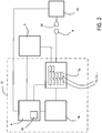
- Fig. 2 is a simplified schedule of the battery pack 7a and associated components of the vehicle 1. All components shown in Fig. 1 are not shown in Fig. 2 .
- the battery pack 7a comprises a number of battery cells C1, C2, C3, ... etc. (also referred to with reference numeral "C") which according to an embodiment is suitably in the magnitude of 200 cells, although the specific number may vary.
- the battery cells are of the lithium ion type, although the principles of the invention are equally applicable to other types of battery cells.
- the battery pack 7a is connected to the electric machine 3 and is configured for operating said electric machine 3 (which in turn operates the vehicle 1). Furthermore, the battery pack 7a is connected to a sensor unit 7b, which in turn is connected to the control unit 8. As mentioned above, the invention is configured for monitoring the status of the battery pack 7a, i.e. to monitor the status of the battery cells C. For this reason, and according to an embodiment, the sensor unit 7b is configured for measuring the voltage (V) of each battery cell and for transmitting information related to measured voltage values to the control unit 8.
- V voltage
- Fig. 2 also shows in a schematic manner the first connector 9, forming part of the vehicle, and the second connector 10, forming part of the external power supply 11. Consequently, the battery pack 7a, the sensor unit 7b and the control unit 8 can be said to constitute a battery management system 12 which is arranged for monitoring the status of the battery cells C1, C2 etc. More precisely, there are three main objectives of the battery management system 12; firstly, to provide an internal state estimation of parameters such as the state of charge (SOC), the state of power, the state of health etc. of the battery pack 7a; secondly, to provide a cell balancing procedure (which requires measurements of the state of charge and voltage of all battery cells); and thirdly, to provide fault handling in case conditions such as over-charging or over-heating has been detected.
- SOC state of charge
- cell balancing procedure which requires measurements of the state of charge and voltage of all battery cells
- fault handling in case conditions such as over-charging or over-heating has been detected.
- the status of the battery pack 7a and its battery cells C can be described with parameters such as its state of charge (SOC) and state of health (SOH).
- SOC state of charge
- SOH state of health
- the state of charge (SOC) corresponds to the remaining amount of charge in the battery pack 7a and is for this reason estimated continuously.
- the stage of health (SOH) can be estimated by measuring the cell capacity (Ah) of each battery cell C and also by measuring the ohmic resistance (ohms) of each battery cell C.
- An important purpose of the battery management system 12 is to ensure safe and efficient operating conditions for the battery pack 7a and for the entire vehicle 1. In particular, it is necessary to monitor important parameter related to the status of the battery pack 7a, such as the state of charge (SOH) of the battery pack 7a and the state of health (SOH) of the battery pack 7a and its battery cells C.
- SOH state of charge
- SOH state of health
- control unit 8 is configured for detecting faults related to the operation of the battery pack by means of the voltage measurements, i.e. in the event that the result of the measurement deviates from an expected value or interval of values.
- a fault could be the result of a premature ageing of a battery cell.
- a fault should be understood to be a deviation of a least one parameter which is related to the battery pack 7a from an acceptable condition.
- the battery management system 12 may be configured for measuring other parameters which are indicators of the state of operation of the battery pack 7a.
- such parameters can be the battery current (I) or the battery temperature (T). Both these parameters can be used for controlling the status of the battery pack 7a.
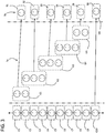
- a number of battery cells C1, C2, C3, ... C10 (i.e. C1-C10) which are arranged in series, i.e. so that they together form a unit having a voltage which is constituted by the sum of each individual voltage of each battery cell C1-C10.
- the example shown in Fig. 3 comprises ten individual battery cells C1-C10, but the invention can be implemented with generally any number of battery cells arranged in a battery pack.
- the sensor unit 7b (see also Figs. 1 and 2 ) so as to provide a measurement of at least one parameter which reflects the state of operation of the battery pack 7a by means of said sensor unit 7b.
- a measurement of the voltage (V) of each battery cell C1-C10 by means of said sensor unit 7b. The measured voltage values are then used for determining important properties of the battery pack such as the state of charge, cell capacity and cell temperature. This will be described in greater detail below.
- the sensor unit 7b comprises a number of voltage sensors S1, S2,..., S6 (also referred to as "S1-S6").
- a sensor unit may comprise a voltage sensor for each battery cell in a battery pack.
- it uses a hierarchical model in order to reduce the number of necessary voltage sensors and in order to minimize the complexity of computations in the control unit. In this manner, the cost-efficiency of the complete sensor unit and control unit can be increased.
- the embodiment shown in Fig. 3 is configured so that the battery pack 1 is arranged in a manner so that the battery cells C1-C10 are arranged in a plurality of groups of battery cells. This is indicated with reference numerals G1, G2..., G6 in Fig 3 . It should be noted that both those groups which contain two or more battery cells (such as the group G1, containing two battery cells C1, C2) and those groups which contain only one single battery cell (such as the group G6, which contains only the battery cell (C10) are referred to as "groups" in the context of this invention.
- each of these groups of cells G1-G6 are connected to the sensor unit 7b, in particular so that:
- the invention is based on a hierarchical model which is decomposed into a collection of sub-systems.
- a number of sensors S1-S6 which is less than the number of battery cells C1-C10 is provided, which leads to a concept which is more cost-efficient that previously known solutions.
- This concept will now be described with reference to an example: if the first sensor S1 - which is associated with the first group G1 - does not indicate any error (for example in the form of a detected voltage level which is lower than a certain threshold level) and if the second sensor S2 indicates that there is an error, it can be assumed that either the third battery cell C3 or the fourth battery cell C4 is faulty. If the third sensor S3 (which is associated with the third group G3) does not indicate any error, it can ultimately be assumed that it is the third battery cell C3 which is the faulty one.
- the embodiment shown in Fig. 3 is arranged so that the groups of cells G1-G6 are configured so that at least two of the groups G1-G6 comprise two or more cells, and also so that at least two of the groups G1-G6 overlap so that a battery cell (for example battery cell C2 in Fig. 3 ) forms part of the overlapping groups.
- the sensor unit 7b is connected to the groups G1-G6 in a manner so that each of the groups G1-G6 is connected to a corresponding sensor S1-S6 which forms part of the sensor unit 7b.
- the sensor unit 7b is arranged so that there is one estimation of a measured value per group.
- the number of groups G1-G6 is less than the number of cells C1-C10.
- the groups G1-G6 of battery cells C1-C10 are arranged in a manner so that it fulfils the following relationship: number of groups ⁇ number of cells / 2 ⁇ 1
- the sensors S1-S6 are configured for measuring at least one parameter related to the state of operation of the battery cells C1-C10.
- the terminal voltage (V) of the battery cells C1-C10 is used as the relevant sensor signal.
- the measured voltage values can be used in the control unit 8 for estimating a certain property of the battery cells C1-C10 or groups of cells G1-G6.
- the control unit 8 is arranged for estimating the state of charge.
- other properties such as the cell capacity for each battery cell C1-C10 and the resistance of each battery cell can be determined.
- the battery management system 12 is configured for receiving measurement values from the sensor unit 7b related to at least the battery terminal voltage (V) in order to calculate values relating to the state of charge, the cell capacity and the ohmic resistance of each battery.
- V battery terminal voltage
- the embodiment is suitably arranged so that the control unit 8 (see Fig. 2 ) may generate an indication of a fault in the event that the result of the measurement of any of the above-mentioned parameters (battery terminal voltage (V), battery current (I) and battery temperature (T)) deviates from an expected value.
- V battery terminal voltage
- I battery current
- T battery temperature
- This is suitably carried out using the principles shown in Fig. 3 , i.e. with the battery cells C1-C10 arranged in groups G1-G6 as explained, and with sensors S1-S6 being associated with the groups G1-G6.
- the battery management system 12 issues an indication or a warning signal.
- the present invention is not limited to the embodiments described above and illustrated in the drawings; rather, the skilled person will recognize that many changes and modifications may be made within the scope of the appended claims.
- V terminal voltage
- T temperature
- I battery current
- the present invention can be implemented in any vehicle, full electric or hybrid electric, comprising an energy storage system similar to the ones described in the exemplified embodiments.
Landscapes
- Engineering & Computer Science (AREA)
- Power Engineering (AREA)
- Life Sciences & Earth Sciences (AREA)
- Sustainable Development (AREA)
- Sustainable Energy (AREA)
- Transportation (AREA)
- Mechanical Engineering (AREA)
- General Physics & Mathematics (AREA)
- Physics & Mathematics (AREA)
- Chemical & Material Sciences (AREA)
- Chemical Kinetics & Catalysis (AREA)
- Electrochemistry (AREA)
- General Chemical & Material Sciences (AREA)
- Manufacturing & Machinery (AREA)
- Secondary Cells (AREA)
- Charge And Discharge Circuits For Batteries Or The Like (AREA)
Claims (12)
- Verfahren zum Überwachen des Status einer Vielzahl von verbundenen Batteriezellen (C1 - C10) in einem Batteriepack (7a), wobei das Verfahren umfasst:- Anordnen der Batteriezellen (C1 - C10) in wenigstens zwei Gruppen (G1 - G6) von Zellen;- Verbinden jeder der Gruppen (G1 - G6) von Zellen mit einem entsprechenden Sensor (S1 - S6), der einen Teil einer Sensoreinheit (7b) bildet; und- Bereitstellen einer Messung wenigstens eines Parameters, der den Betriebszustand des Batteriepacks (7a) mittels der Sensoreinheit (7b) anzeigt;dadurch gekennzeichnet, dass das Verfahren ferner umfasst:- Anordnen der Gruppen (G1 - G6) von Zellen (C1 - C10) in einer Weise, so dass:- wenigstens zwei der Gruppen (G1 - G6) zwei oder mehr Zellen umfassen, und- wenigstens zwei der Gruppen (G1 - G6) überlappen, so dass eine Zelle einen Teil der überlappenden Gruppen bildet; und- Verbinden jedes Sensors (S1 - S6) der Sensoreinheit (7b) mit jeder der entsprechenden Gruppen (G1 - G6) zum Schätzen einer Messung des Parameters für jede der Gruppen (G1 - G6); und wobei- die Anzahl von Gruppen (G1 - G6) geringer als die Anzahl von Zellen (C1 - C10) ist.
- Verfahren nach Anspruch 1, dadurch gekennzeichnet, dass es ferner umfasst:- Anordnen der Gruppen (G1 - G6) von Zellen (C1 - C10) in einer Weise, so dass sie das Verhältnis erfüllt:

- Verfahren nach Anspruch 1 oder 2, dadurch gekennzeichnet, dass es ferner umfasst:- Verwenden der Sensoren (S1 - S6) zum Messen wenigstens eines Parameters, der auf den Betriebszustand der Batteriezellen (C1 - C10) bezogen ist, wobei der Parameter wenigstens einer der folgenden ist: der Batteriestrom (I); die Anschlussspannung (V) wenigstens einer Zelle; und die Temperatur (T) wenigstens einer Zelle.
- Verfahren nach Anspruch 3, dadurch gekennzeichnet, dass es ferner umfasst:- Schätzen, basierend auf dem gemessenen Parameter, wenigstens eine der folgenden Eigenschaften jeder Batteriezelle (C1 - C10) oder Gruppe (G1 - G6) von Zellen:- dem Ladungszustand;- der Zellenkapazität; und- dem Widerstand.
- Verfahren nach einem der vorhergehenden Ansprüche, dadurch gekennzeichnet, dass es ferner umfasst:- Erzeugen einer Anzeige eines Fehlers für den Fall, dass das Ergebnis der Messung von einem erwarteten Wert abweicht.
- Batteriemanagementsystem (12) zum Überwachen des Status einer Vielzahl von verbundenen Batteriezellen (C1 - C10) in einem Batteriepack (7a), umfassend:- eine Vielzahl von Batteriezellen (C1 - C10), die in wenigstens zwei Gruppen (G1 - G6) von Zellen angeordnet sind;- eine Sensoreinheit (7b), die mit den Gruppen (G1 - G6) verbunden ist, so dass jede der Gruppen (G1 - G6) mit einem entsprechenden Sensor (S1 - S6) verbunden ist, der einen Teil der Sensoreinheit (7b) bildet; wobei die Sensoreinheit (7b) zum Bereitstellen einer Messung wenigstens eines Parameters konfiguriert ist, der den Betriebszustand des Batteriepacks (7a) anzeigt; und- eine Steuereinheit (8), die mit der Sensoreinheit (7b) verbunden ist;dadurch gekennzeichnet, dass das System ferner umfasst:- eine Anordnung der Gruppen (G1 - G6) von Zellen (C1 - C10), wobei:- wenigstens zwei der Gruppen (G1 - G6) zwei oder mehr Zellen umfassen, und- wenigstens zwei der Gruppen (G1 - G6) überlappen, so dass eine Zelle einen Teil der überlappenden Gruppen bildet; und- eine Verbindung zwischen jedem Sensor (S1 - S6) der Sensoreinheit (7b) und jeder der entsprechenden Gruppen (G1 - G6) zum Schätzen einer Messung des Parameters für jede der Gruppen (G1 - G6); wobei- die Anzahl von Gruppen (G1 - G6) geringer als die Anzahl von Zellen (C1 - C10) ist.
- System (12) nach Anspruch 6, dadurch gekennzeichnet, dass die Sensoren (S1 - S6) zum Messen wenigstens eines Parameters konfiguriert sind, der auf den Betriebszustand der Batteriezellen (C1 - C10) bezogen ist, wobei der Parameter wenigstens einer der folgenden ist: der Batteriestrom (I); die Anschlussspannung (V) wenigstens einer Zelle; und die Temperatur (T) wenigstens einer Zelle.
- System(12) nach Anspruch 6 oder 7, dadurch gekennzeichnet, dass die Steuereinheit (4) dazu konfiguriert ist, eine Anzeige eines Fehlers für den Fall zu erzeugen, dass das Ergebnis der Messung von einem erwarteten Wert abweicht.
- Fahrzeug (1) umfassend ein Batteriemanagementsystem (12) nach einem der Ansprüche 6-8.
- Computerprogramm umfassend Programmcodemittel zum Durchführen der Verfahrensschritte nach einem der Ansprüche 1-5, wenn das Programm auf einem Computer läuft.
- Computerlesbares Medium, auf dem ein Computerprogramm gespeichert ist, das Programmcodemittel zum Durchführen der Schritte nach einem der Ansprüche 1-5 umfasst, wenn das Programm auf einem Computer läuft.
- Steuereinheit (8) zum Überwachen des Status einer Vielzahl von verbundenen Batteriezellen (C1 - C10) in einem Batteriepack (7a), wobei die Steuereinheit (8) dazu konfiguriert ist, die Schritte des Verfahrens nach einem der Ansprüche 1-5 durchzuführen.
Applications Claiming Priority (1)
| Application Number | Priority Date | Filing Date | Title |
|---|---|---|---|
| PCT/EP2014/001477 WO2015185070A1 (en) | 2014-06-02 | 2014-06-02 | A method and system for monitoring the status of battery cells |
Publications (2)
| Publication Number | Publication Date |
|---|---|
| EP3149499A1 EP3149499A1 (de) | 2017-04-05 |
| EP3149499B1 true EP3149499B1 (de) | 2018-01-31 |
Family
ID=51178853
Family Applications (1)
| Application Number | Title | Priority Date | Filing Date |
|---|---|---|---|
| EP14739031.4A Active EP3149499B1 (de) | 2014-06-02 | 2014-06-02 | Verfahren und system zur überwachung des status von batteriezellen |
Country Status (3)
| Country | Link |
|---|---|
| US (1) | US10151801B2 (de) |
| EP (1) | EP3149499B1 (de) |
| WO (1) | WO2015185070A1 (de) |
Families Citing this family (12)
| Publication number | Priority date | Publication date | Assignee | Title |
|---|---|---|---|---|
| EP3149499B1 (de) * | 2014-06-02 | 2018-01-31 | Volvo Truck Corporation | Verfahren und system zur überwachung des status von batteriezellen |
| CN107923942B (zh) * | 2015-05-08 | 2020-11-20 | 沃尔沃卡车集团 | 用于监测电池组中的多个电池单体的状态的方法 |
| DE102016112173A1 (de) * | 2016-07-04 | 2018-01-04 | Dr. Ing. H.C. F. Porsche Aktiengesellschaft | Verfahren zur Einstellung |
| CN106200629B (zh) * | 2016-09-30 | 2018-07-13 | 山东科技大学 | 一种无人机飞行控制系统的故障可检测度分析方法 |
| CN106325264B (zh) * | 2016-11-04 | 2018-08-14 | 山东科技大学 | 一种无人机飞行控制系统的故障可分离性评价方法 |
| WO2018153431A1 (en) * | 2017-02-21 | 2018-08-30 | Volvo Truck Corporation | A method and arrangement for balancing a battery pack |
| EP3743307B1 (de) * | 2018-01-25 | 2023-11-22 | Volvo Construction Equipment AB | Entzerrerüberlastungsmanagement |
| CN108845270B (zh) * | 2018-07-11 | 2021-01-05 | 国网江西省电力有限公司电力科学研究院 | 磷酸铁锂动力电池梯次利用的全寿命周期成本估算方法 |
| EP4079560A1 (de) * | 2021-04-23 | 2022-10-26 | Volvo Truck Corporation | Verfahren zur verbesserung der verfügbarkeit eines energiespeichers oder energieumwandlungssystems |
| JP7567823B2 (ja) * | 2022-02-04 | 2024-10-16 | トヨタ自動車株式会社 | 電池モジュールの診断システムおよび車両 |
| US12330623B2 (en) | 2022-05-04 | 2025-06-17 | Toyota Motor North America, Inc. | Vehicle battery element management |
| EP4465409A1 (de) * | 2023-05-16 | 2024-11-20 | Volvo Truck Corporation | Perforierter geschichteter zellseparator zur verringerung der thermischen ausbreitung |
Family Cites Families (23)
| Publication number | Priority date | Publication date | Assignee | Title |
|---|---|---|---|---|
| US6332113B1 (en) * | 1996-10-07 | 2001-12-18 | Midtronics, Inc. | Electronic battery tester |
| FR2776139B1 (fr) | 1998-03-13 | 2002-03-08 | Denso Corp | Dispositif d'equilibrage des tensions dans une batterie composee |
| JP3936169B2 (ja) | 2001-11-06 | 2007-06-27 | パナソニック・イーブイ・エナジー株式会社 | 組電池システムの異常検出方法及び装置 |
| JP3867581B2 (ja) * | 2002-01-17 | 2007-01-10 | 松下電器産業株式会社 | 組電池システム |
| US6972544B2 (en) * | 2003-10-14 | 2005-12-06 | Black & Decker Inc. | Apparatus for interconnecting battery cells in a battery pack and method thereof |
| JP4374351B2 (ja) * | 2006-04-12 | 2009-12-02 | 矢崎総業株式会社 | 充電状態調整装置 |
| KR100778414B1 (ko) * | 2006-10-12 | 2007-11-22 | 삼성에스디아이 주식회사 | 배터리 관리 시스템 및 그의 구동 방법 |
| US8519670B2 (en) * | 2009-03-23 | 2013-08-27 | Motiv Power Systems, Inc. | System and method for balancing charge within a battery pack |
| JP5133926B2 (ja) | 2009-03-26 | 2013-01-30 | 株式会社日立製作所 | 車両用電池システム |
| JP2011154986A (ja) * | 2010-01-28 | 2011-08-11 | Sanyo Electric Co Ltd | 電池パック |
| JP5299397B2 (ja) * | 2010-10-18 | 2013-09-25 | 株式会社デンソー | 電池状態監視装置 |
| JP5152310B2 (ja) * | 2010-12-03 | 2013-02-27 | 株式会社デンソー | 組電池の電圧検出装置 |
| WO2012090473A1 (ja) * | 2010-12-29 | 2012-07-05 | 川崎重工業株式会社 | 電池モジュールの充電システム |
| JP5353914B2 (ja) * | 2011-02-01 | 2013-11-27 | 株式会社デンソー | 電池電圧監視装置 |
| JP5825904B2 (ja) * | 2011-07-27 | 2015-12-02 | 矢崎総業株式会社 | 電池状態通知ユニット、バスバモジュール、組電池、及び、電池状態監視システム |
| KR101669114B1 (ko) * | 2012-04-30 | 2016-10-25 | 삼성에스디아이 주식회사 | 모듈화 구조가 적용된 배터리 팩 |
| JP5932569B2 (ja) * | 2012-08-24 | 2016-06-08 | ルネサスエレクトロニクス株式会社 | 半導体装置及び電池電圧監視装置 |
| US9318781B2 (en) * | 2013-01-11 | 2016-04-19 | Johnson Controls Technology Company | Predicted sensor information for a battery |
| JP6523607B2 (ja) * | 2013-04-08 | 2019-06-05 | 株式会社Gsユアサ | バッテリモジュール |
| KR20140140355A (ko) * | 2013-05-29 | 2014-12-09 | 삼성에스디아이 주식회사 | 배터리 관리 시스템 및 그 구동 방법 |
| EP3149499B1 (de) * | 2014-06-02 | 2018-01-31 | Volvo Truck Corporation | Verfahren und system zur überwachung des status von batteriezellen |
| CN107923942B (zh) * | 2015-05-08 | 2020-11-20 | 沃尔沃卡车集团 | 用于监测电池组中的多个电池单体的状态的方法 |
| CN110178244B (zh) * | 2016-12-29 | 2023-01-03 | 罗密欧系统公司 | 用于电池结构、互连、感测和平衡的系统和方法 |
-
2014
- 2014-06-02 EP EP14739031.4A patent/EP3149499B1/de active Active
- 2014-06-02 WO PCT/EP2014/001477 patent/WO2015185070A1/en not_active Ceased
- 2014-06-02 US US15/307,726 patent/US10151801B2/en active Active
Also Published As
| Publication number | Publication date |
|---|---|
| EP3149499A1 (de) | 2017-04-05 |
| US20170074945A1 (en) | 2017-03-16 |
| US10151801B2 (en) | 2018-12-11 |
| WO2015185070A1 (en) | 2015-12-10 |
Similar Documents
| Publication | Publication Date | Title |
|---|---|---|
| EP3149499B1 (de) | Verfahren und system zur überwachung des status von batteriezellen | |
| US20210055355A1 (en) | Method for monitoring the status of a plurality of battery cells in a battery pack | |
| US10115247B2 (en) | Method and arrangement for controlling charging of an electrical storage system in a vehicle including measuring power loss over connector elements during charging and generating an error signal based on power loss | |
| US10259338B2 (en) | Method and system for optimizing the lifetime of an energy storage system | |
| US9937815B2 (en) | Method and arrangement for balancing an energy storage system | |
| CN110167783B (zh) | 一种用于确定电池组的充电状态的方法和装置 | |
| US20210247450A1 (en) | Battery diagnosis apparatus and vehicle | |
| EP3245096A1 (de) | Verfahren und anordnung zur bestimmung eines wertes des energiezustands einer batterie in einem fahrzeug | |
| EP3585642B1 (de) | Verfahren und system zum ausgleichen eines batteriepacks | |
| EP3545320A1 (de) | Verfahren und anordnung zur klassifizierung einer spannungsstörung in einem elektrischen speichersystem | |
| CN107064608A (zh) | 用于诊断电池电压误报的方法和系统 | |
| EP4180828B1 (de) | Vorrichtung zur diagnose der verschlechterung einer batterie und verfahren zur diagnose der verschlechterung einer batterie | |
| JP2022148131A (ja) | 車両の電源制御システム | |
| US20250370057A1 (en) | Battery pack |
Legal Events
| Date | Code | Title | Description |
|---|---|---|---|
| PUAI | Public reference made under article 153(3) epc to a published international application that has entered the european phase |
Free format text: ORIGINAL CODE: 0009012 |
|
| 17P | Request for examination filed |
Effective date: 20161215 |
|
| AK | Designated contracting states |
Kind code of ref document: A1 Designated state(s): AL AT BE BG CH CY CZ DE DK EE ES FI FR GB GR HR HU IE IS IT LI LT LU LV MC MK MT NL NO PL PT RO RS SE SI SK SM TR |
|
| AX | Request for extension of the european patent |
Extension state: BA ME |
|
| GRAP | Despatch of communication of intention to grant a patent |
Free format text: ORIGINAL CODE: EPIDOSNIGR1 |
|
| RIC1 | Information provided on ipc code assigned before grant |
Ipc: G01R 31/36 20060101AFI20170629BHEP Ipc: H01M 10/42 20060101ALI20170629BHEP Ipc: B60L 11/18 20060101ALI20170629BHEP Ipc: H01M 10/48 20060101ALI20170629BHEP |
|
| DAX | Request for extension of the european patent (deleted) | ||
| INTG | Intention to grant announced |
Effective date: 20170728 |
|
| GRAJ | Information related to disapproval of communication of intention to grant by the applicant or resumption of examination proceedings by the epo deleted |
Free format text: ORIGINAL CODE: EPIDOSDIGR1 |
|
| GRAR | Information related to intention to grant a patent recorded |
Free format text: ORIGINAL CODE: EPIDOSNIGR71 |
|
| GRAS | Grant fee paid |
Free format text: ORIGINAL CODE: EPIDOSNIGR3 |
|
| GRAA | (expected) grant |
Free format text: ORIGINAL CODE: 0009210 |
|
| INTC | Intention to grant announced (deleted) | ||
| RIC1 | Information provided on ipc code assigned before grant |
Ipc: G01R 31/36 20060101AFI20171130BHEP Ipc: B60L 3/00 20060101ALI20171130BHEP Ipc: B60L 11/18 20060101ALI20171130BHEP Ipc: H01M 10/48 20060101ALI20171130BHEP Ipc: H01M 10/42 20060101ALI20171130BHEP |
|
| INTG | Intention to grant announced |
Effective date: 20171214 |
|
| AK | Designated contracting states |
Kind code of ref document: B1 Designated state(s): AL AT BE BG CH CY CZ DE DK EE ES FI FR GB GR HR HU IE IS IT LI LT LU LV MC MK MT NL NO PL PT RO RS SE SI SK SM TR |
|
| REG | Reference to a national code |
Ref country code: GB Ref legal event code: FG4D Ref country code: CH Ref legal event code: EP |
|
| REG | Reference to a national code |
Ref country code: AT Ref legal event code: REF Ref document number: 967876 Country of ref document: AT Kind code of ref document: T Effective date: 20180215 |
|
| REG | Reference to a national code |
Ref country code: IE Ref legal event code: FG4D |
|
| REG | Reference to a national code |
Ref country code: DE Ref legal event code: R096 Ref document number: 602014020422 Country of ref document: DE |
|
| REG | Reference to a national code |
Ref country code: SE Ref legal event code: TRGR |
|
| REG | Reference to a national code |
Ref country code: NL Ref legal event code: MP Effective date: 20180131 |
|
| REG | Reference to a national code |
Ref country code: LT Ref legal event code: MG4D |
|
| REG | Reference to a national code |
Ref country code: FR Ref legal event code: PLFP Year of fee payment: 5 |
|
| REG | Reference to a national code |
Ref country code: AT Ref legal event code: MK05 Ref document number: 967876 Country of ref document: AT Kind code of ref document: T Effective date: 20180131 |
|
| PG25 | Lapsed in a contracting state [announced via postgrant information from national office to epo] |
Ref country code: NO Free format text: LAPSE BECAUSE OF FAILURE TO SUBMIT A TRANSLATION OF THE DESCRIPTION OR TO PAY THE FEE WITHIN THE PRESCRIBED TIME-LIMIT Effective date: 20180430 Ref country code: ES Free format text: LAPSE BECAUSE OF FAILURE TO SUBMIT A TRANSLATION OF THE DESCRIPTION OR TO PAY THE FEE WITHIN THE PRESCRIBED TIME-LIMIT Effective date: 20180131 Ref country code: HR Free format text: LAPSE BECAUSE OF FAILURE TO SUBMIT A TRANSLATION OF THE DESCRIPTION OR TO PAY THE FEE WITHIN THE PRESCRIBED TIME-LIMIT Effective date: 20180131 Ref country code: FI Free format text: LAPSE BECAUSE OF FAILURE TO SUBMIT A TRANSLATION OF THE DESCRIPTION OR TO PAY THE FEE WITHIN THE PRESCRIBED TIME-LIMIT Effective date: 20180131 Ref country code: LT Free format text: LAPSE BECAUSE OF FAILURE TO SUBMIT A TRANSLATION OF THE DESCRIPTION OR TO PAY THE FEE WITHIN THE PRESCRIBED TIME-LIMIT Effective date: 20180131 Ref country code: NL Free format text: LAPSE BECAUSE OF FAILURE TO SUBMIT A TRANSLATION OF THE DESCRIPTION OR TO PAY THE FEE WITHIN THE PRESCRIBED TIME-LIMIT Effective date: 20180131 |
|
| PG25 | Lapsed in a contracting state [announced via postgrant information from national office to epo] |
Ref country code: BG Free format text: LAPSE BECAUSE OF FAILURE TO SUBMIT A TRANSLATION OF THE DESCRIPTION OR TO PAY THE FEE WITHIN THE PRESCRIBED TIME-LIMIT Effective date: 20180430 Ref country code: LV Free format text: LAPSE BECAUSE OF FAILURE TO SUBMIT A TRANSLATION OF THE DESCRIPTION OR TO PAY THE FEE WITHIN THE PRESCRIBED TIME-LIMIT Effective date: 20180131 Ref country code: IS Free format text: LAPSE BECAUSE OF FAILURE TO SUBMIT A TRANSLATION OF THE DESCRIPTION OR TO PAY THE FEE WITHIN THE PRESCRIBED TIME-LIMIT Effective date: 20180531 Ref country code: GR Free format text: LAPSE BECAUSE OF FAILURE TO SUBMIT A TRANSLATION OF THE DESCRIPTION OR TO PAY THE FEE WITHIN THE PRESCRIBED TIME-LIMIT Effective date: 20180501 Ref country code: PL Free format text: LAPSE BECAUSE OF FAILURE TO SUBMIT A TRANSLATION OF THE DESCRIPTION OR TO PAY THE FEE WITHIN THE PRESCRIBED TIME-LIMIT Effective date: 20180131 Ref country code: RS Free format text: LAPSE BECAUSE OF FAILURE TO SUBMIT A TRANSLATION OF THE DESCRIPTION OR TO PAY THE FEE WITHIN THE PRESCRIBED TIME-LIMIT Effective date: 20180131 Ref country code: AT Free format text: LAPSE BECAUSE OF FAILURE TO SUBMIT A TRANSLATION OF THE DESCRIPTION OR TO PAY THE FEE WITHIN THE PRESCRIBED TIME-LIMIT Effective date: 20180131 |
|
| PG25 | Lapsed in a contracting state [announced via postgrant information from national office to epo] |
Ref country code: RO Free format text: LAPSE BECAUSE OF FAILURE TO SUBMIT A TRANSLATION OF THE DESCRIPTION OR TO PAY THE FEE WITHIN THE PRESCRIBED TIME-LIMIT Effective date: 20180131 Ref country code: IT Free format text: LAPSE BECAUSE OF FAILURE TO SUBMIT A TRANSLATION OF THE DESCRIPTION OR TO PAY THE FEE WITHIN THE PRESCRIBED TIME-LIMIT Effective date: 20180131 Ref country code: AL Free format text: LAPSE BECAUSE OF FAILURE TO SUBMIT A TRANSLATION OF THE DESCRIPTION OR TO PAY THE FEE WITHIN THE PRESCRIBED TIME-LIMIT Effective date: 20180131 Ref country code: EE Free format text: LAPSE BECAUSE OF FAILURE TO SUBMIT A TRANSLATION OF THE DESCRIPTION OR TO PAY THE FEE WITHIN THE PRESCRIBED TIME-LIMIT Effective date: 20180131 |
|
| REG | Reference to a national code |
Ref country code: DE Ref legal event code: R097 Ref document number: 602014020422 Country of ref document: DE |
|
| PG25 | Lapsed in a contracting state [announced via postgrant information from national office to epo] |
Ref country code: DK Free format text: LAPSE BECAUSE OF FAILURE TO SUBMIT A TRANSLATION OF THE DESCRIPTION OR TO PAY THE FEE WITHIN THE PRESCRIBED TIME-LIMIT Effective date: 20180131 Ref country code: CZ Free format text: LAPSE BECAUSE OF FAILURE TO SUBMIT A TRANSLATION OF THE DESCRIPTION OR TO PAY THE FEE WITHIN THE PRESCRIBED TIME-LIMIT Effective date: 20180131 Ref country code: SK Free format text: LAPSE BECAUSE OF FAILURE TO SUBMIT A TRANSLATION OF THE DESCRIPTION OR TO PAY THE FEE WITHIN THE PRESCRIBED TIME-LIMIT Effective date: 20180131 Ref country code: SM Free format text: LAPSE BECAUSE OF FAILURE TO SUBMIT A TRANSLATION OF THE DESCRIPTION OR TO PAY THE FEE WITHIN THE PRESCRIBED TIME-LIMIT Effective date: 20180131 |
|
| PLBE | No opposition filed within time limit |
Free format text: ORIGINAL CODE: 0009261 |
|
| STAA | Information on the status of an ep patent application or granted ep patent |
Free format text: STATUS: NO OPPOSITION FILED WITHIN TIME LIMIT |
|
| 26N | No opposition filed |
Effective date: 20181102 |
|
| REG | Reference to a national code |
Ref country code: CH Ref legal event code: PL |
|
| GBPC | Gb: european patent ceased through non-payment of renewal fee |
Effective date: 20180602 |
|
| REG | Reference to a national code |
Ref country code: BE Ref legal event code: MM Effective date: 20180630 |
|
| REG | Reference to a national code |
Ref country code: IE Ref legal event code: MM4A |
|
| PG25 | Lapsed in a contracting state [announced via postgrant information from national office to epo] |
Ref country code: LU Free format text: LAPSE BECAUSE OF NON-PAYMENT OF DUE FEES Effective date: 20180602 Ref country code: MC Free format text: LAPSE BECAUSE OF FAILURE TO SUBMIT A TRANSLATION OF THE DESCRIPTION OR TO PAY THE FEE WITHIN THE PRESCRIBED TIME-LIMIT Effective date: 20180131 |
|
| PG25 | Lapsed in a contracting state [announced via postgrant information from national office to epo] |
Ref country code: GB Free format text: LAPSE BECAUSE OF NON-PAYMENT OF DUE FEES Effective date: 20180602 Ref country code: IE Free format text: LAPSE BECAUSE OF NON-PAYMENT OF DUE FEES Effective date: 20180602 Ref country code: CH Free format text: LAPSE BECAUSE OF NON-PAYMENT OF DUE FEES Effective date: 20180630 Ref country code: LI Free format text: LAPSE BECAUSE OF NON-PAYMENT OF DUE FEES Effective date: 20180630 |
|
| PG25 | Lapsed in a contracting state [announced via postgrant information from national office to epo] |
Ref country code: BE Free format text: LAPSE BECAUSE OF NON-PAYMENT OF DUE FEES Effective date: 20180630 |
|
| PG25 | Lapsed in a contracting state [announced via postgrant information from national office to epo] |
Ref country code: MT Free format text: LAPSE BECAUSE OF NON-PAYMENT OF DUE FEES Effective date: 20180602 |
|
| PG25 | Lapsed in a contracting state [announced via postgrant information from national office to epo] |
Ref country code: TR Free format text: LAPSE BECAUSE OF FAILURE TO SUBMIT A TRANSLATION OF THE DESCRIPTION OR TO PAY THE FEE WITHIN THE PRESCRIBED TIME-LIMIT Effective date: 20180131 |
|
| PG25 | Lapsed in a contracting state [announced via postgrant information from national office to epo] |
Ref country code: PT Free format text: LAPSE BECAUSE OF FAILURE TO SUBMIT A TRANSLATION OF THE DESCRIPTION OR TO PAY THE FEE WITHIN THE PRESCRIBED TIME-LIMIT Effective date: 20180131 |
|
| PG25 | Lapsed in a contracting state [announced via postgrant information from national office to epo] |
Ref country code: HU Free format text: LAPSE BECAUSE OF FAILURE TO SUBMIT A TRANSLATION OF THE DESCRIPTION OR TO PAY THE FEE WITHIN THE PRESCRIBED TIME-LIMIT; INVALID AB INITIO Effective date: 20140602 Ref country code: CY Free format text: LAPSE BECAUSE OF FAILURE TO SUBMIT A TRANSLATION OF THE DESCRIPTION OR TO PAY THE FEE WITHIN THE PRESCRIBED TIME-LIMIT Effective date: 20180131 Ref country code: MK Free format text: LAPSE BECAUSE OF NON-PAYMENT OF DUE FEES Effective date: 20180131 |
|
| PG25 | Lapsed in a contracting state [announced via postgrant information from national office to epo] |
Ref country code: SI Free format text: LAPSE BECAUSE OF NON-PAYMENT OF DUE FEES Effective date: 20180602 |
|
| PGFP | Annual fee paid to national office [announced via postgrant information from national office to epo] |
Ref country code: FR Payment date: 20240625 Year of fee payment: 11 |
|
| PGFP | Annual fee paid to national office [announced via postgrant information from national office to epo] |
Ref country code: DE Payment date: 20250626 Year of fee payment: 12 |
|
| PGFP | Annual fee paid to national office [announced via postgrant information from national office to epo] |
Ref country code: SE Payment date: 20250619 Year of fee payment: 12 |
|
| PG25 | Lapsed in a contracting state [announced via postgrant information from national office to epo] |
Ref country code: FR Free format text: LAPSE BECAUSE OF NON-PAYMENT OF DUE FEES Effective date: 20250630 |