EP3149527B1 - Dispositif pour l'orientation sphérique d'un élément optique, en particulier afin de diriger un faisceau lumineux, tel qu'un faisceau laser - Google Patents
Dispositif pour l'orientation sphérique d'un élément optique, en particulier afin de diriger un faisceau lumineux, tel qu'un faisceau laser Download PDFInfo
- Publication number
- EP3149527B1 EP3149527B1 EP15736611.3A EP15736611A EP3149527B1 EP 3149527 B1 EP3149527 B1 EP 3149527B1 EP 15736611 A EP15736611 A EP 15736611A EP 3149527 B1 EP3149527 B1 EP 3149527B1
- Authority
- EP
- European Patent Office
- Prior art keywords
- optical element
- rotation axis
- axis
- around
- relative
- Prior art date
- Legal status (The legal status is an assumption and is not a legal conclusion. Google has not performed a legal analysis and makes no representation as to the accuracy of the status listed.)
- Active
Links
Images




Classifications
-
- F—MECHANICAL ENGINEERING; LIGHTING; HEATING; WEAPONS; BLASTING
- F21—LIGHTING
- F21V—FUNCTIONAL FEATURES OR DETAILS OF LIGHTING DEVICES OR SYSTEMS THEREOF; STRUCTURAL COMBINATIONS OF LIGHTING DEVICES WITH OTHER ARTICLES, NOT OTHERWISE PROVIDED FOR
- F21V14/00—Controlling the distribution of the light emitted by adjustment of elements
- F21V14/04—Controlling the distribution of the light emitted by adjustment of elements by movement of reflectors
-
- G—PHYSICS
- G02—OPTICS
- G02B—OPTICAL ELEMENTS, SYSTEMS OR APPARATUS
- G02B7/00—Mountings, adjusting means, or light-tight connections, for optical elements
- G02B7/18—Mountings, adjusting means, or light-tight connections, for optical elements for prisms; for mirrors
- G02B7/182—Mountings, adjusting means, or light-tight connections, for optical elements for prisms; for mirrors for mirrors
- G02B7/1821—Mountings, adjusting means, or light-tight connections, for optical elements for prisms; for mirrors for mirrors for rotating or oscillating mirrors
-
- A—HUMAN NECESSITIES
- A61—MEDICAL OR VETERINARY SCIENCE; HYGIENE
- A61B—DIAGNOSIS; SURGERY; IDENTIFICATION
- A61B18/00—Surgical instruments, devices or methods for transferring non-mechanical forms of energy to or from the body
- A61B18/18—Surgical instruments, devices or methods for transferring non-mechanical forms of energy to or from the body by applying electromagnetic radiation, e.g. microwaves
- A61B18/20—Surgical instruments, devices or methods for transferring non-mechanical forms of energy to or from the body by applying electromagnetic radiation, e.g. microwaves using laser
-
- F—MECHANICAL ENGINEERING; LIGHTING; HEATING; WEAPONS; BLASTING
- F21—LIGHTING
- F21V—FUNCTIONAL FEATURES OR DETAILS OF LIGHTING DEVICES OR SYSTEMS THEREOF; STRUCTURAL COMBINATIONS OF LIGHTING DEVICES WITH OTHER ARTICLES, NOT OTHERWISE PROVIDED FOR
- F21V7/00—Reflectors for light sources
- F21V7/0008—Reflectors for light sources providing for indirect lighting
-
- G—PHYSICS
- G02—OPTICS
- G02B—OPTICAL ELEMENTS, SYSTEMS OR APPARATUS
- G02B26/00—Optical devices or arrangements for the control of light using movable or deformable optical elements
- G02B26/08—Optical devices or arrangements for the control of light using movable or deformable optical elements for controlling the direction of light
- G02B26/10—Scanning systems
- G02B26/101—Scanning systems with both horizontal and vertical deflecting means, e.g. raster or XY scanners
-
- A—HUMAN NECESSITIES
- A61—MEDICAL OR VETERINARY SCIENCE; HYGIENE
- A61B—DIAGNOSIS; SURGERY; IDENTIFICATION
- A61B18/00—Surgical instruments, devices or methods for transferring non-mechanical forms of energy to or from the body
- A61B18/18—Surgical instruments, devices or methods for transferring non-mechanical forms of energy to or from the body by applying electromagnetic radiation, e.g. microwaves
- A61B18/20—Surgical instruments, devices or methods for transferring non-mechanical forms of energy to or from the body by applying electromagnetic radiation, e.g. microwaves using laser
- A61B2018/2015—Miscellaneous features
Definitions
- the present invention relates to a device for the spherical orientation of an optical element.
- devices which are used for the orientation of an optical element. Especially, though not exclusively, these devices can be used for the motor-driven control of the direction of a beam of light in the space.
- One of the possible fields of application of these devices is - for example - that of laser (micro)surgery.
- devices of the type mentioned above which are manually operated, so as to orient - in the space - a mirror that causes the light beam to converge and points it based on its position.
- One drawback is due to the fact that they are not suited to be used in combination with optical elements that can be passed through by a light beam (also known as see-through elements), since the mechanisms used are provided with rotary assemblies that interfere with the trajectory of the incident light beam that is suited to interact with the optical element.
- known mechanisms are also affected by the drawback of obstructing - or being an obstacle for - the line of sight of an observer wanting to see through the optical element (typically, from the top to the bottom or, anyway, in a direction that is substantially orthogonal to the light beam).
- DE 10 2012 012 780 A1 describes a mirror system to deflect a laser beam.
- the system described therein comprises a suspension device to support the mirror, so as to allow it to rotate around two orthogonal axes, and an operating device to move the mirror.
- the suspension device has a first inner frame, where the mirror is held so as to be able to rotate around a first axis, and a second outer frame, where the first inner frame is held so as to be able to rotate around a second axis.
- the operating device is provided with two linear actuator units, each coupled in an articulated and symmetrical manner relative to the other one.
- the two linear actuators are arranged at a distance from one another, substantially extend in parallel directions and can be controlled separately, so as to carry out a rotation of the mirror in a desired position.
- DE 20 2011 110290 U1 discloses an optoelectronic sensor, in particular a laser scanner, which has a light transmitter for emitting a light beam.
- a deflection unit is rotatable about an axis of rotation for periodic deflection of the light beam.
- a pivoting device is configured for pivoting the deflection unit about a pivot axis transversely to the axis of rotation.
- There is a light receiver for generating a received signal from the light beam remitted or reflected in the monitoring area.
- An evaluation unit is designed for the detection of objects in the monitoring area on the basis of the received signal.
- the pivoting device has a lifting axis element which is connected to the deflection unit and whose translational movement along the axis of rotation causes the pivoting movement of the deflection unit.
- EP 2 256 397 A1 discloses a spherical orienting device comprising a base, first and second actuation shafts, an orientable device, an inner member, a middle member, and an outer member.
- the first and second actuation shafts are rotatably held by the base for rotary actuation about first and second actuation axes, which intersect orthogonally at a spherical centre of rotation.
- the orientable device is supported by first and second revolute support joints, the first support joint being disposed for rotation about an orientation axis of the orientable device and the second support joint being disposed for rotation about a support axis, which orthogonally intersects the orientation axis at the spherical centre of rotation.
- the inner member is fixed to the first actuation shaft and linked to the second support joint, the first actuation axis being disposed orthogonal to the support axis.
- the middle member is inwardly linked to the first support joint and outwardly linked to a middle revolute joint disposed for rotation about a linkage axis, which passes through the spherical centre of rotation and is disposed orthogonal to the orientation axis.
- the outer member is fixed to the second actuation shaft and linked to the middle revolute joint, the linkage axis being disposed orthogonal to the second actuation axis.
- LINOS Catalog 2003, Goettingen, Germany, XP055812656, pages L19-L21 discloses several manually adjustable optic holders.
- An object of the present invention is to provide a device, which is able to solve the aforesaid drawbacks of the prior art and which, at the same time, can be produced in a simple and economic fashion.
- the device according to the present invention also allows not only the trajectory (generally oriented horizontally) of the light beam to be pointed at the optical element, but also the line of sight of an observer wanting to see through the optical element to be free and not obstructed.
- the line of sight typically is transverse relative to the trajectory of the light beam; in particular, in use, it is oriented from the top to the bottom or, anyway, in a direction that is substantially orthogonal to the light beam.
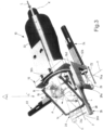
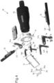
- Figures from 1 to 3 show, in different perspectives and from different angles, a device for the spherical orientation of an optical element, shown in the same operating configuration. This device is indicated, as a whole, with number 10.
- device 10 is designed to be used to point a light beam, such as a laser beam.
- a light beam such as a laser beam.
- One of the possible fields of application for the aforesaid device is - for example - that of laser (micro) surgery.
- device 10 can be operated so as to orient, in the desired arrangement in the space, the optical element (e.g. a mirror), which causes the beam of light L to converge and points it based on the position assumed by said optical element.
- the optical element e.g. a mirror
- device 10 can also be used, more generically, to point different optical elements in different fields of application.
- this device can be used to orient optical elements, such as sensors or lenses, in the space for different purposes.
- Device 10 comprises a support structure 12 and an optical element 14 having an optically useful surface (not numbered), for interacting with an incident light beam L (e.g. a laser beam); in particular, said surface having an orientation axis O defining its position in the space.
- the device comprises, furthermore, a mechanism 16, which is mounted on the support structure 12 and is able to position optical element 14 by causing it to rotate around a first and a second fixed rotation axes X and Y, which are perpendicular to one another.
- the rotation of optical element 14 around the first axis X and the rotation of optical element 14 around the second axis Y can be controlled separately and independently of one another, thus granting to optical element 14 two degrees of freedom in its movements.
- light beam L pointed at optical element 14 is able to be direct at any point having x,y coordinates and arranged on a reference surface (for example, a surgical site in the explanatory case of laser surgery), which is faced by the optically useful surface of optical element 14.
- mechanism 16 comprises a first rotary assembly 18, which is articulated, relative to optical element 14, around a first mobile support axis A, which is rotary and perpendicular relative to the first rotation axis X.
- the first rotary assembly 18, furthermore, is coupled, in a rotary manner, to support structure 12 so as to rotate around the first rotation axis X, in order to cause optical element 14 (in particular, through rotation of orientation axis O) to rotate around said first rotation axis X, and allowing said optical element 14 to rotate around the first mobile support axis A.
- mechanism 16 comprises a second rotary assembly 20, which is articulated, relative to optical element 14, around a second mobile support axis B, which is rotary relative to the second rotation axis Y and perpendicular to the first mobile support axis A.
- the second rotary assembly 20, furthermore, is coupled, in a rotary manner, to support structure 12 so as to rotate around the second rotation axis Y, in order to cause optical element 14 (in particular, through rotation of orientation axis O) to rotate around the second rotation axis Y, and allowing said optical element 14 to rotate around the second support axis B.
- the first rotary assembly 18 has a through cavity 18a defined around the first rotation axis X, for being passed through by a light beam (e.g. a laser beam) and faces optical element 14.
- a light beam e.g. a laser beam
- Device 10 comprises, furthermore, a first linear actuator 22 (for example an electrically operated one), for causing the first rotary assembly 18 to rotate, thus exerting upon the latter a stress (in particular, a pushing or pulling stress) in a first actuating direction Z1 that is transversely spaced apart relative to the first rotation axis X and to through cavity 18a.
- a first linear actuator 22 for example an electrically operated one
- a stress in particular, a pushing or pulling stress
- device 10 comprises a second linear actuator 24, for causing the second rotary assembly 20 to rotate, thus exerting upon the latter a stress (in particular, a pushing or pulling stress) in a second actuating direction Z2 that is transversely spaced apart relative to the second rotation axis Y and to through cavity 18a.
- a stress in particular, a pushing or pulling stress
- device 10 is operated in a way that is quick and precise at the same time and, furthermore, the user is allowed to also use optical elements 14 that can be passed through by the light beam (also known as see-through devices).
- optical elements 14 can be a polarizer or a semi-transparent mirror or - more generically - a beam splitter.
- the use of the pair of linear actuators instead of the rotary motors typically used in the prior art documents allows manufacturers to obtain a greater angular rotation speed (which, by mere way of example, can be 14 time greater) and, at the same time, a greater angular resolution (which, by mere way of example, can be 20 times greater).
- the aforesaid configuration of device 10 does not simply free the trajectory (generally oriented horizontally) of the light beam to be pointed at optical element 14.
- this configuration also prevents mechanism 16 from obstructing the line of sight of an observer wanting to see through optical element 14, as shown by way of example in figures 2 , 3 and 10 .
- This line of sight, indicated with L' typically is transverse and orthogonal relative to the trajectory of light beam L; in particular, in use, it is oriented from the top to the bottom.
- This advantage therefore, is especially important and appreciated in case the optical element is a see-through element, for example a transparent or semi-transparent one.
- optical element 14 comprises a frame 15, which surrounds at least part of its outer perimeter.
- the first linear actuator 22 is fixed to support structure 12.
- support structure 12 comprises a bracket 12a, which projects outwards and to which the first linear actuator 22 is fixed.
- the second linear actuator 24 is fixed to support structure 12.
- support structure 12 comprises a further bracket 12b, which projects outwards and to which the first linear actuator 22 is fixed.
- the rotary coupling obtained around the second fixed rotation axis Y and arranged between the second rotary assembly 20 and support structure 12 is made in correspondence to the further bracket 12b.
- the first linear actuator 22 comprises a mobile member 22a, which can be moved in the first actuating direction Z1 and is able to act upon the first rotary assembly 18, so as to cause a rotation thereof around the first fixed rotation axis X.
- the first actuating direction Z1 is substantially parallel to the second fixed rotation axis Y.
- the second linear actuator 24 comprises a mobile member 24a, which can be moved in the second actuating direction Z2 and is able to act upon said second rotary assembly 20, so as to cause a rotation thereof around the second fixed rotation axis Y.
- the second actuating direction Z2 is substantially parallel to the first fixed rotation axis X.
- the first and the second actuating directions Z1 and Z2 are substantially perpendicular, in particular for an observer looking at device 10 shown in the figures from a point of observation overlooking the plan view and substantially orthogonal to the plane defined by the fixed rotation axes X, Y.
- actuating directions Z1 and Z2 have slightly different distances relative to the plane defined by the fixed rotation axes X, Y.
- the first assembly 18 comprises a tubular portion 18b, which defines through cavity 18a and is housed, in a turning manner, in a substantially cylindrical seat (not numbered) obtained through support structure 12.
- the first assembly 18 comprises, furthermore, an arm 18c, which transversely projects outwards relative to the first fixed rotation axis X and is suited to be stressed (through pushing or pulling) by the first linear actuator 22.
- arm 18c transversely projects from tubular portion 18b, in particular from the axial end thereof.
- mobile member 22a is designed to stress (through pushing or pulling) arm 18c.
- arm 18d is articulated relative to the first mobile member 22a, for example through the interposition of a first articulation indicated, as a whole, with number 25.
- mobile member 22a is hinged, relative to arm 18d, around a first mobile hinge axis (not numbered), which, for example, is parallel to and spaced apart from the first rotations axis X.
- the first assembly 18 comprises a pair of axial appendages 18d, which axially project outwards and on which optical element 14 is articulated - and preferably hinged - around the first mobile support axis A.
- the pair of axial appendages 18d extend on diametrically opposite sides of tubular portion 18b.
- the axial appendages 18d comprise a pair of L-shaped brackets, which are fixed (for example screwed) at their base to tubular portion 18b.
- optical element 18 is articulated - and in particular hinged - to the first rotary assembly 18 in correspondence to frame 15.
- the first assembly can comprise one single axial appendage, which axially projects outwards and on which the optical element is articulated - and preferably hinged - around the first mobile support axis.
- the second rotary assembly 20 is articulated to a peripheral portion 14a of optical element 14 (for example, in correspondence to a peripheral edge of the optical element) around the second mobile support axis B.
- peripheral portion 14a is arranged in an intermediate part of the peripheral edge of optical element 14.
- the aforesaid peripheral portion 14a can be placed along frame 15.
- the second rotary assembly 20 comprises a connecting segment 26, which, on one side, is articulated (and in particular hinged), relative to said optical element 14, around said second mobile support axis B and, on the other side, is articulated (and in particular hinged), relative to the rest of rotary assembly 20, around a mobile articulation axis C, which is rotary and perpendicular relative to the second rotation axis Y.
- mobile articulation axis C passes through the intersection between the fixed rotation axes X and Y.
- device 10 is shown in a configuration in which mobile articulation axis C is in a position that is substantially coaxial to the first fixed rotation axis X, but this axis can move and rotate around the second fixed rotation axis Y, upwards or downwards relative to the aforesaid first fixed rotation axis X.
- connecting segment 26 is preferably articulated (and in particular hinged) to peripheral portion 14a around support axis B.
- the second assembly 20 comprises a lever 28, which is mounted on support structure 12 so as to rotate around the second fixed rotation axis Y.
- lever 28 is a rocker arm and, more preferably, it is substantially L-shaped and it is pivoted around the second rotation axis Y in correspondence to the intersection between its two lever arms 28a, 28b.
- lever 28 is supported, during its rotation, by support structure 12 in correspondence to the further bracket 12b.
- rocker arm 28 has a lever arm 28a, which is suited to be stressed (through pushing or pulling) by the second linear actuator 24, and the other lever arm 28b is suited to impart a rotation towards optical element 14.
- the second mobile member 24a is suited to stress (through pushing or pulling) lever arm 28a.
- lever arm 28a is articulated relative to the second mobile member 24a, for example through the interposition of a second articulation indicated, as a whole, with number 29.
- the second mobile member 24a is hinged, relative to lever arm 21d, around a second mobile hinge axis (not numbered), which, for example, is parallel to and spaced apart from the second rotations axis Y.
- lever arm 28a and the other lever arm 28b substantially lie on a plane that is perpendicular to the rotation axis Y.
- the second rotary assembly 20 comprises a transverse segment 30, which is connected to lever 28 and substantially departs transversely from said lever 28 towards the first fixed rotation axis X.
- transverse segment 30 extends substantially parallel to the second fixed rotation axis X.
- transverse segment 30 departs from lever 28 in correspondence to the other lever arm 28b, in particular in correspondence to the latter.
- connecting segment 26 is articulated - in particular hinged - to transverse segment 30 around intermediate articulation axis C.
- connecting segment 26 has a shape that is substantially bent towards optical element 14.
- connecting segment 26 comprises a proximal portion 26a, which departs from transverse segment 30 in a direction that is substantially perpendicular relative to mobile articulation axis C. Furthermore, connecting segment 26 also comprises a distal portion 26b, which is inclined at approximately 45° towards optical element 14 relative to the direction of proximal portion 40a.
- distal portion 26b is articulated - in particular hinged - to optical element 14 around the second support axis B, on the opposite side relative to proximal portion 26a.
- distal portion 26b is articulated - in particular hinged - to peripheral portion 14a of optical element 14 around the second support axis B.
- device 10 comprises, furthermore, a known light beam generator 32, for emitting the light beam, pointing it through through cavity 18a.
- light beam generator 32 is fixed to support structure 12 in a position that is aligned relative to through cavity 18a and, in particular, coaxial to the first fixed rotation axis X.
- optical element 14 is a mirror, for reflecting incident light beam L towards the point of intersection of support axes A and B, corresponding to its center of rotation (in particular, from which orientation axis O departs perpendicularly).
- said mirror is flat, for example with a substantially rectangular shape.
- the first linear actuator 22 when the first linear actuator 22 is operated, the first mobile member 22a is translated along the first actuating direction Z1. In this way, the first mobile member 22a stresses arm 18c, by pushing or pulling it, which causes the simultaneous rotation of tubular portion 18b around the first fixed rotation axis X. Consequently, axial appendages 18d rotate in an integral manner with said tubular portion 18b, thus rotating with them (around the first fixed rotation axis X) the first support axis A, on which optical element 14 is hinged. Therefore, by so doing, incident light beam L can be pointed at optical element 14 moving it along an axis x (see figure 2 ).
- first actuator 22 and the second actuator 24 can be operated at the same time, so that they can move optical element 14 in the space.
- the optional assembling of connecting segment 26 relative to the rest of the second rotary assembly 20, thanks to the freedom of rotation relative to mobile hinge axis C, permits the simultaneous operation of linear actuators 22 and 24, without any interference with the movements of rotary assemblies 18 and 20 of mechanism 16.
Landscapes
- Physics & Mathematics (AREA)
- Optics & Photonics (AREA)
- General Physics & Mathematics (AREA)
- Engineering & Computer Science (AREA)
- Health & Medical Sciences (AREA)
- Surgery (AREA)
- General Engineering & Computer Science (AREA)
- Life Sciences & Earth Sciences (AREA)
- Electromagnetism (AREA)
- Otolaryngology (AREA)
- Nuclear Medicine, Radiotherapy & Molecular Imaging (AREA)
- Biomedical Technology (AREA)
- Heart & Thoracic Surgery (AREA)
- Medical Informatics (AREA)
- Molecular Biology (AREA)
- Animal Behavior & Ethology (AREA)
- General Health & Medical Sciences (AREA)
- Public Health (AREA)
- Veterinary Medicine (AREA)
- Laser Surgery Devices (AREA)
- Mechanical Light Control Or Optical Switches (AREA)
Claims (9)
- Dispositif (10) pour l'orientation sphérique d'un élément optique (14) ; ledit dispositif (10) comprenant :- une structure de support (12),- un élément optique (14) ayant une surface optiquement utile pour réfléchir un faisceau lumineux (L) incident, en particulier un faisceau laser, et- un mécanisme (16), qui est monté sur ladite structure de support (12) et est apte à amener ledit élément optique (14) à tourner dans l'espace autour d'un premier et d'un deuxième axes de rotation fixes (X, Y), qui sont perpendiculaires l'un à l'autre ; ledit mécanisme (16) comprenant :un premier ensemble rotatif (18), qui est articulé, par rapport audit élément optique (14), autour d'un premier axe de support mobile (A), qui est rotatif et perpendiculaire par rapport au premier axe de rotation (X), ledit premier ensemble rotatif (18) étant également couplé, d'une manière rotative, à la structure de support (12) de manière à tourner autour du premier axe de rotation (X), afin d'amener l'élément optique (14) à tourner autour dudit premier axe de rotation (X), et permettant audit élément optique (14) de tourner autour dudit premier axe de support mobile (A) ;un deuxième ensemble rotatif (20), qui est articulé, par rapport audit élément optique (14), autour d'un deuxième axe de support mobile (B), qui est rotatif par rapport audit deuxième axe de rotation (Y) et perpendiculaire audit premier axe de support mobile (A), ledit deuxième ensemble rotatif (20) étant également couplé, d'une manière rotative, à la structure de support (12) de manière à tourner autour dudit deuxième axe de rotation (X), afin d'amener ledit élément optique (14) à tourner autour dudit deuxième axe de rotation (Y), et permettant audit élément optique (14) de tourner autour dudit deuxième axe de support (B) ;ledit dispositif (10) comprenant en outre un générateur de faisceau lumineux (32) configuré pour émettre ledit faisceau lumineux (L) ;ledit dispositif (10) étant caractérisé en ce qu'il comprend en outre :- un premier actionneur linéaire (22), qui est apte à amener ledit premier ensemble rotatif (18) à tourner, en exerçant ainsi sur celui-ci une contrainte dans une première direction d'actionnement (Z1) qui est espacée transversalement par rapport audit premier axe de rotation (X) et à ladite cavité traversante (18a) ; et- un deuxième actionneur linéaire (24), pour amener ledit deuxième ensemble rotatif (20) à tourner, en exerçant ainsi sur celui-ci une contrainte dans une deuxième direction d'actionnement (Z2) qui est espacée par rapport audit deuxième axe de rotation (Y) et à ladite cavité traversante (18a) ;ledit premier ensemble rotatif (18) a une cavité traversante (18a) définie autour dudit premier axe de rotation (X) et apte à être traversée et pointée par ledit faisceau lumineux (L) émis par ledit générateur de faisceau lumineux (32) ;dans lequel ledit premier ensemble rotatif (18) fait face audit élément optique (14) ; ledit élément optique (14) étant apte à être traversé par une ligne de vision d'un observateur (L'), qui est sensiblement orientée transversalement par rapport audit faisceau lumineux (L) incident ;dans lequel lesdites première et deuxième directions d'actionnement (Z1, Z2) sont sensiblement perpendiculaires.
- Dispositif selon la revendication 1, dans lequel ledit premier actionneur linéaire (22) comprend un élément mobile (22a), qui peut être déplacé dans la première direction d'actionnement (Z1) et est apte à agir sur le premier ensemble rotatif (18), de manière à provoquer une rotation dudit premier ensemble rotatif (18) autour dudit premier axe de rotation fixe (X).
- Dispositif selon la revendication 1 ou 2, dans lequel ladite première direction d'actionnement (Z1) est sensiblement parallèle au deuxième axe de rotation fixe (Y) .
- Dispositif selon l'une quelconque des revendications précédentes, dans lequel ledit deuxième actionneur linéaire (24) comprend un élément mobile (24a), qui peut être déplacé dans la deuxième direction d'actionnement (Z2) et est apte à agir sur ledit deuxième ensemble rotatif (20), de manière à provoquer une rotation dudit deuxième ensemble rotatif (20) autour dudit deuxième axe de rotation fixe (Y).
- Dispositif selon l'une quelconque des revendications précédentes, dans lequel ladite deuxième direction d'actionnement (Z2) est sensiblement parallèle audit premier axe de rotation fixe (X).
- Dispositif selon l'une quelconque des revendications précédentes, dans lequel ledit premier ensemble (18) comprend une partie tubulaire (18b), qui définit ladite cavité traversante (18a) et est logée, de manière à pouvoir tourner, dans un siège sensiblement cylindrique obtenu à travers ladite structure de support (12).
- Dispositif selon l'une quelconque des revendications précédentes, dans lequel ledit premier ensemble (18) comprend en outre un bras (18c) faisant saillie transversalement vers l'extérieur par rapport audit premier axe de rotation fixe (X) et apte à être contraint par ledit premier actionneur linéaire (22).
- Dispositif selon l'une quelconque des revendications précédentes, dans lequel ledit deuxième ensemble rotatif (20) est articulé à une partie périphérique (14a) dudit élément optique (14) autour dudit deuxième axe de support mobile (B).
- Dispositif selon l'une quelconque des revendications précédentes, dans lequel ledit deuxième ensemble rotatif (20) comprend un segment de liaison (26) qui, d'un côté, est articulé, par rapport audit élément optique (14), autour dudit deuxième axe de support mobile (B) et, de l'autre côté, est articulé, par rapport au reste dudit ensemble rotatif (20), autour d'un axe d'articulation mobile (C) qui est rotatif et perpendiculaire par rapport audit deuxième axe de rotation (Y).
Applications Claiming Priority (2)
| Application Number | Priority Date | Filing Date | Title |
|---|---|---|---|
| ITTO20140432 | 2014-05-30 | ||
| PCT/IB2015/054021 WO2015181771A1 (fr) | 2014-05-30 | 2015-05-28 | Dispositif pour l'orientation sphérique d'un élément optique, en particulier afin de diriger un faisceau lumineux, tel qu'un faisceau laser |
Publications (3)
| Publication Number | Publication Date |
|---|---|
| EP3149527A1 EP3149527A1 (fr) | 2017-04-05 |
| EP3149527B1 true EP3149527B1 (fr) | 2023-08-02 |
| EP3149527C0 EP3149527C0 (fr) | 2023-08-02 |
Family
ID=51220804
Family Applications (1)
| Application Number | Title | Priority Date | Filing Date |
|---|---|---|---|
| EP15736611.3A Active EP3149527B1 (fr) | 2014-05-30 | 2015-05-28 | Dispositif pour l'orientation sphérique d'un élément optique, en particulier afin de diriger un faisceau lumineux, tel qu'un faisceau laser |
Country Status (4)
| Country | Link |
|---|---|
| US (1) | US10738973B2 (fr) |
| EP (1) | EP3149527B1 (fr) |
| IL (1) | IL249037B (fr) |
| WO (1) | WO2015181771A1 (fr) |
Families Citing this family (6)
| Publication number | Priority date | Publication date | Assignee | Title |
|---|---|---|---|---|
| CN107290839B (zh) * | 2017-05-15 | 2019-08-09 | 北京空间机电研究所 | 一种采用定位限位装置的高稳定度主备光路切换机构 |
| WO2019204324A1 (fr) | 2018-04-16 | 2019-10-24 | The Regents Of The University Of California | Stabilisation et commande de position linéaire et angulaire d'un système robotique sous-marin |
| CN110275270B (zh) * | 2019-06-21 | 2024-07-02 | 辽宁中蓝光电科技有限公司 | 旋转模块 |
| CN110568581B (zh) * | 2019-09-09 | 2021-09-03 | 哈尔滨工业大学 | 一种高精度电动反射镜架 |
| IT202000002155A1 (it) | 2020-02-04 | 2021-08-04 | Fondazione St Italiano Tecnologia | Dispositivo per l’orientamento sferico di un elemento ottico, in particolare per dirigere un fascio di luce, quale un fascio laser |
| CN115657250B (zh) * | 2022-11-08 | 2024-07-09 | 哈尔滨工业大学 | 一种光学元件拆装结构 |
Citations (2)
| Publication number | Priority date | Publication date | Assignee | Title |
|---|---|---|---|---|
| EP2256397A1 (fr) * | 2009-05-26 | 2010-12-01 | Robert Bosch GmbH | Dispositif d'orientation sphérique et son procédé de fabrication |
| DE202011110290U1 (de) * | 2011-07-18 | 2013-04-30 | Sick Ag | Optoelektronischer Sensor |
Family Cites Families (8)
| Publication number | Priority date | Publication date | Assignee | Title |
|---|---|---|---|---|
| US3015249A (en) * | 1949-03-14 | 1962-01-02 | Northrop Corp | Tracking telescope |
| US4886330A (en) * | 1986-08-07 | 1989-12-12 | James Linick | Infra red imaging system |
| US5966991A (en) | 1997-04-23 | 1999-10-19 | Universite Laval | Two degree-of-freedom spherical orienting device |
| EP1929354B1 (fr) | 2005-09-27 | 2017-07-26 | Bishop, Mark, Vincent | Systeme de traitement de signaux energetiques |
| US7688528B2 (en) * | 2006-08-14 | 2010-03-30 | Newport Corporation | Mount for optical component having independent multi-axial control |
| DE102007006414B4 (de) | 2007-02-05 | 2009-12-24 | Deutsches Zentrum für Luft- und Raumfahrt e.V. | Vorrichtung zur Grobausrichtung eines optischen Freiraumstrahls |
| US20110063446A1 (en) | 2009-09-14 | 2011-03-17 | Mcmordie David | Saccadic dual-resolution video analytics camera |
| DE102012012780A1 (de) | 2012-06-26 | 2014-01-02 | Tutech Innovation Gmbh | Parellelkinematisches Spiegel-Ablenksystem mit doppelkardanischer Aufhängung |
-
2015
- 2015-05-28 EP EP15736611.3A patent/EP3149527B1/fr active Active
- 2015-05-28 WO PCT/IB2015/054021 patent/WO2015181771A1/fr not_active Ceased
- 2015-05-28 US US15/315,227 patent/US10738973B2/en active Active
-
2016
- 2016-11-17 IL IL249037A patent/IL249037B/en unknown
Patent Citations (2)
| Publication number | Priority date | Publication date | Assignee | Title |
|---|---|---|---|---|
| EP2256397A1 (fr) * | 2009-05-26 | 2010-12-01 | Robert Bosch GmbH | Dispositif d'orientation sphérique et son procédé de fabrication |
| DE202011110290U1 (de) * | 2011-07-18 | 2013-04-30 | Sick Ag | Optoelektronischer Sensor |
Non-Patent Citations (1)
| Title |
|---|
| "LINOS Catalog 2003", 31 December 2003, LINOS GOETTINGEN GERMANY, G0ettingen, article LINOS: "LINOS Catalog 2003", pages: L19 - L21, XP055812656 * |
Also Published As
| Publication number | Publication date |
|---|---|
| US10738973B2 (en) | 2020-08-11 |
| IL249037A0 (en) | 2017-01-31 |
| US20170198885A1 (en) | 2017-07-13 |
| IL249037B (en) | 2021-12-01 |
| EP3149527A1 (fr) | 2017-04-05 |
| WO2015181771A1 (fr) | 2015-12-03 |
| EP3149527C0 (fr) | 2023-08-02 |
Similar Documents
| Publication | Publication Date | Title |
|---|---|---|
| EP3149527B1 (fr) | Dispositif pour l'orientation sphérique d'un élément optique, en particulier afin de diriger un faisceau lumineux, tel qu'un faisceau laser | |
| CN111033119B (zh) | 照明系统 | |
| US6817976B2 (en) | Deviated distal viewing endoscope | |
| US3796220A (en) | Stereo laser endoscope | |
| US10660719B2 (en) | Master interface device for a motorised endoscopic system and installation comprising such a device | |
| JP6549584B2 (ja) | 2次元前方走査プローブ | |
| US20210190919A1 (en) | Detection system using optical scanning element with glass body and reflective member | |
| GB1579254A (en) | Laser optical apparatus | |
| US5652676A (en) | Microscope-television camera adapter | |
| JP2013504391A5 (fr) | ||
| EP2590002A1 (fr) | Affichage proche orientable et système d'affichage proche orientable | |
| JP2004267774A (ja) | 医療光学機器のためのスタンド装置 | |
| CN101273296B (zh) | 能量信号处理系统 | |
| CN106569328B (zh) | 五杆机构、摆镜系统及二维摆镜装置 | |
| WO2014000041A1 (fr) | Centre de rotation distant mécanique | |
| JP5838327B2 (ja) | 内視鏡 | |
| WO2016149686A1 (fr) | Articulation de bras conique | |
| JP6292558B2 (ja) | 内視鏡 | |
| JP2013024867A (ja) | 光電センサ並びに物体検出及び距離測定方法 | |
| US12461359B2 (en) | Device for the spherical orientation of an optical element, in particular for directing a light beam, such as a laser beam | |
| CN109730693A (zh) | 一种新型管状结构三视场光学手持探头 | |
| JP3650140B2 (ja) | 手術用顕微鏡 | |
| US11231578B2 (en) | Scanner arrangement for optical radiation | |
| JP2022518051A (ja) | 相関関数を決定するためのテクニカルステージ装置および方法 | |
| JP3318041B2 (ja) | 手術用顕微鏡 |
Legal Events
| Date | Code | Title | Description |
|---|---|---|---|
| STAA | Information on the status of an ep patent application or granted ep patent |
Free format text: STATUS: THE INTERNATIONAL PUBLICATION HAS BEEN MADE |
|
| PUAI | Public reference made under article 153(3) epc to a published international application that has entered the european phase |
Free format text: ORIGINAL CODE: 0009012 |
|
| STAA | Information on the status of an ep patent application or granted ep patent |
Free format text: STATUS: REQUEST FOR EXAMINATION WAS MADE |
|
| 17P | Request for examination filed |
Effective date: 20161123 |
|
| AK | Designated contracting states |
Kind code of ref document: A1 Designated state(s): AL AT BE BG CH CY CZ DE DK EE ES FI FR GB GR HR HU IE IS IT LI LT LU LV MC MK MT NL NO PL PT RO RS SE SI SK SM TR |
|
| AX | Request for extension of the european patent |
Extension state: BA ME |
|
| DAV | Request for validation of the european patent (deleted) | ||
| DAX | Request for extension of the european patent (deleted) | ||
| STAA | Information on the status of an ep patent application or granted ep patent |
Free format text: STATUS: EXAMINATION IS IN PROGRESS |
|
| 17Q | First examination report despatched |
Effective date: 20210617 |
|
| GRAP | Despatch of communication of intention to grant a patent |
Free format text: ORIGINAL CODE: EPIDOSNIGR1 |
|
| STAA | Information on the status of an ep patent application or granted ep patent |
Free format text: STATUS: GRANT OF PATENT IS INTENDED |
|
| INTG | Intention to grant announced |
Effective date: 20230426 |
|
| GRAS | Grant fee paid |
Free format text: ORIGINAL CODE: EPIDOSNIGR3 |
|
| GRAA | (expected) grant |
Free format text: ORIGINAL CODE: 0009210 |
|
| STAA | Information on the status of an ep patent application or granted ep patent |
Free format text: STATUS: THE PATENT HAS BEEN GRANTED |
|
| AK | Designated contracting states |
Kind code of ref document: B1 Designated state(s): AL AT BE BG CH CY CZ DE DK EE ES FI FR GB GR HR HU IE IS IT LI LT LU LV MC MK MT NL NO PL PT RO RS SE SI SK SM TR |
|
| REG | Reference to a national code |
Ref country code: GB Ref legal event code: FG4D |
|
| REG | Reference to a national code |
Ref country code: CH Ref legal event code: EP |
|
| REG | Reference to a national code |
Ref country code: DE Ref legal event code: R096 Ref document number: 602015084900 Country of ref document: DE |
|
| REG | Reference to a national code |
Ref country code: IE Ref legal event code: FG4D |
|
| U01 | Request for unitary effect filed |
Effective date: 20230810 |
|
| U07 | Unitary effect registered |
Designated state(s): AT BE BG DE DK EE FI FR IT LT LU LV MT NL PT SE SI Effective date: 20230817 |
|
| PG25 | Lapsed in a contracting state [announced via postgrant information from national office to epo] |
Ref country code: GR Free format text: LAPSE BECAUSE OF FAILURE TO SUBMIT A TRANSLATION OF THE DESCRIPTION OR TO PAY THE FEE WITHIN THE PRESCRIBED TIME-LIMIT Effective date: 20231103 |
|
| PG25 | Lapsed in a contracting state [announced via postgrant information from national office to epo] |
Ref country code: IS Free format text: LAPSE BECAUSE OF FAILURE TO SUBMIT A TRANSLATION OF THE DESCRIPTION OR TO PAY THE FEE WITHIN THE PRESCRIBED TIME-LIMIT Effective date: 20231202 |
|
| PG25 | Lapsed in a contracting state [announced via postgrant information from national office to epo] |
Ref country code: RS Free format text: LAPSE BECAUSE OF FAILURE TO SUBMIT A TRANSLATION OF THE DESCRIPTION OR TO PAY THE FEE WITHIN THE PRESCRIBED TIME-LIMIT Effective date: 20230802 Ref country code: NO Free format text: LAPSE BECAUSE OF FAILURE TO SUBMIT A TRANSLATION OF THE DESCRIPTION OR TO PAY THE FEE WITHIN THE PRESCRIBED TIME-LIMIT Effective date: 20231102 Ref country code: IS Free format text: LAPSE BECAUSE OF FAILURE TO SUBMIT A TRANSLATION OF THE DESCRIPTION OR TO PAY THE FEE WITHIN THE PRESCRIBED TIME-LIMIT Effective date: 20231202 Ref country code: HR Free format text: LAPSE BECAUSE OF FAILURE TO SUBMIT A TRANSLATION OF THE DESCRIPTION OR TO PAY THE FEE WITHIN THE PRESCRIBED TIME-LIMIT Effective date: 20230802 Ref country code: GR Free format text: LAPSE BECAUSE OF FAILURE TO SUBMIT A TRANSLATION OF THE DESCRIPTION OR TO PAY THE FEE WITHIN THE PRESCRIBED TIME-LIMIT Effective date: 20231103 |
|
| PG25 | Lapsed in a contracting state [announced via postgrant information from national office to epo] |
Ref country code: PL Free format text: LAPSE BECAUSE OF FAILURE TO SUBMIT A TRANSLATION OF THE DESCRIPTION OR TO PAY THE FEE WITHIN THE PRESCRIBED TIME-LIMIT Effective date: 20230802 |
|
| PG25 | Lapsed in a contracting state [announced via postgrant information from national office to epo] |
Ref country code: ES Free format text: LAPSE BECAUSE OF FAILURE TO SUBMIT A TRANSLATION OF THE DESCRIPTION OR TO PAY THE FEE WITHIN THE PRESCRIBED TIME-LIMIT Effective date: 20230802 |
|
| PG25 | Lapsed in a contracting state [announced via postgrant information from national office to epo] |
Ref country code: SM Free format text: LAPSE BECAUSE OF FAILURE TO SUBMIT A TRANSLATION OF THE DESCRIPTION OR TO PAY THE FEE WITHIN THE PRESCRIBED TIME-LIMIT Effective date: 20230802 Ref country code: RO Free format text: LAPSE BECAUSE OF FAILURE TO SUBMIT A TRANSLATION OF THE DESCRIPTION OR TO PAY THE FEE WITHIN THE PRESCRIBED TIME-LIMIT Effective date: 20230802 Ref country code: ES Free format text: LAPSE BECAUSE OF FAILURE TO SUBMIT A TRANSLATION OF THE DESCRIPTION OR TO PAY THE FEE WITHIN THE PRESCRIBED TIME-LIMIT Effective date: 20230802 Ref country code: CZ Free format text: LAPSE BECAUSE OF FAILURE TO SUBMIT A TRANSLATION OF THE DESCRIPTION OR TO PAY THE FEE WITHIN THE PRESCRIBED TIME-LIMIT Effective date: 20230802 Ref country code: SK Free format text: LAPSE BECAUSE OF FAILURE TO SUBMIT A TRANSLATION OF THE DESCRIPTION OR TO PAY THE FEE WITHIN THE PRESCRIBED TIME-LIMIT Effective date: 20230802 |
|
| REG | Reference to a national code |
Ref country code: DE Ref legal event code: R097 Ref document number: 602015084900 Country of ref document: DE |
|
| PLBE | No opposition filed within time limit |
Free format text: ORIGINAL CODE: 0009261 |
|
| STAA | Information on the status of an ep patent application or granted ep patent |
Free format text: STATUS: NO OPPOSITION FILED WITHIN TIME LIMIT |
|
| U20 | Renewal fee for the european patent with unitary effect paid |
Year of fee payment: 10 Effective date: 20240515 |
|
| 26N | No opposition filed |
Effective date: 20240503 |
|
| REG | Reference to a national code |
Ref country code: CH Ref legal event code: PL |
|
| PG25 | Lapsed in a contracting state [announced via postgrant information from national office to epo] |
Ref country code: MC Free format text: LAPSE BECAUSE OF FAILURE TO SUBMIT A TRANSLATION OF THE DESCRIPTION OR TO PAY THE FEE WITHIN THE PRESCRIBED TIME-LIMIT Effective date: 20230802 |
|
| PG25 | Lapsed in a contracting state [announced via postgrant information from national office to epo] |
Ref country code: MC Free format text: LAPSE BECAUSE OF FAILURE TO SUBMIT A TRANSLATION OF THE DESCRIPTION OR TO PAY THE FEE WITHIN THE PRESCRIBED TIME-LIMIT Effective date: 20230802 Ref country code: CH Free format text: LAPSE BECAUSE OF NON-PAYMENT OF DUE FEES Effective date: 20240531 |
|
| PG25 | Lapsed in a contracting state [announced via postgrant information from national office to epo] |
Ref country code: IE Free format text: LAPSE BECAUSE OF NON-PAYMENT OF DUE FEES Effective date: 20240528 |
|
| U20 | Renewal fee for the european patent with unitary effect paid |
Year of fee payment: 11 Effective date: 20250507 |
|
| PGFP | Annual fee paid to national office [announced via postgrant information from national office to epo] |
Ref country code: GB Payment date: 20250401 Year of fee payment: 11 |
|
| PG25 | Lapsed in a contracting state [announced via postgrant information from national office to epo] |
Ref country code: CY Free format text: LAPSE BECAUSE OF FAILURE TO SUBMIT A TRANSLATION OF THE DESCRIPTION OR TO PAY THE FEE WITHIN THE PRESCRIBED TIME-LIMIT; INVALID AB INITIO Effective date: 20150528 |
|
| PG25 | Lapsed in a contracting state [announced via postgrant information from national office to epo] |
Ref country code: HU Free format text: LAPSE BECAUSE OF FAILURE TO SUBMIT A TRANSLATION OF THE DESCRIPTION OR TO PAY THE FEE WITHIN THE PRESCRIBED TIME-LIMIT; INVALID AB INITIO Effective date: 20150528 |