EP3149578B1 - Regroupement de machines virtuelles dans une application en nuage - Google Patents
Regroupement de machines virtuelles dans une application en nuage Download PDFInfo
- Publication number
- EP3149578B1 EP3149578B1 EP15800625.4A EP15800625A EP3149578B1 EP 3149578 B1 EP3149578 B1 EP 3149578B1 EP 15800625 A EP15800625 A EP 15800625A EP 3149578 B1 EP3149578 B1 EP 3149578B1
- Authority
- EP
- European Patent Office
- Prior art keywords
- virtual machine
- application
- management server
- identifier
- unique
- Prior art date
- Legal status (The legal status is an assumption and is not a legal conclusion. Google has not performed a legal analysis and makes no representation as to the accuracy of the status listed.)
- Active
Links
Images


Classifications
-
- G—PHYSICS
- G06—COMPUTING OR CALCULATING; COUNTING
- G06F—ELECTRIC DIGITAL DATA PROCESSING
- G06F9/00—Arrangements for program control, e.g. control units
- G06F9/06—Arrangements for program control, e.g. control units using stored programs, i.e. using an internal store of processing equipment to receive or retain programs
- G06F9/44—Arrangements for executing specific programs
- G06F9/455—Emulation; Interpretation; Software simulation, e.g. virtualisation or emulation of application or operating system execution engines
- G06F9/45533—Hypervisors; Virtual machine monitors
- G06F9/45558—Hypervisor-specific management and integration aspects
-
- G—PHYSICS
- G06—COMPUTING OR CALCULATING; COUNTING
- G06F—ELECTRIC DIGITAL DATA PROCESSING
- G06F8/00—Arrangements for software engineering
- G06F8/60—Software deployment
- G06F8/65—Updates
-
- G—PHYSICS
- G06—COMPUTING OR CALCULATING; COUNTING
- G06F—ELECTRIC DIGITAL DATA PROCESSING
- G06F9/00—Arrangements for program control, e.g. control units
- G06F9/06—Arrangements for program control, e.g. control units using stored programs, i.e. using an internal store of processing equipment to receive or retain programs
- G06F9/44—Arrangements for executing specific programs
- G06F9/455—Emulation; Interpretation; Software simulation, e.g. virtualisation or emulation of application or operating system execution engines
- G06F9/45533—Hypervisors; Virtual machine monitors
- G06F9/45558—Hypervisor-specific management and integration aspects
- G06F2009/45562—Creating, deleting, cloning virtual machine instances
-
- G—PHYSICS
- G06—COMPUTING OR CALCULATING; COUNTING
- G06F—ELECTRIC DIGITAL DATA PROCESSING
- G06F9/00—Arrangements for program control, e.g. control units
- G06F9/06—Arrangements for program control, e.g. control units using stored programs, i.e. using an internal store of processing equipment to receive or retain programs
- G06F9/44—Arrangements for executing specific programs
- G06F9/455—Emulation; Interpretation; Software simulation, e.g. virtualisation or emulation of application or operating system execution engines
- G06F9/45533—Hypervisors; Virtual machine monitors
- G06F9/45558—Hypervisor-specific management and integration aspects
- G06F2009/4557—Distribution of virtual machine instances; Migration and load balancing
-
- G—PHYSICS
- G06—COMPUTING OR CALCULATING; COUNTING
- G06F—ELECTRIC DIGITAL DATA PROCESSING
- G06F9/00—Arrangements for program control, e.g. control units
- G06F9/06—Arrangements for program control, e.g. control units using stored programs, i.e. using an internal store of processing equipment to receive or retain programs
- G06F9/44—Arrangements for executing specific programs
- G06F9/455—Emulation; Interpretation; Software simulation, e.g. virtualisation or emulation of application or operating system execution engines
- G06F9/45533—Hypervisors; Virtual machine monitors
- G06F9/45558—Hypervisor-specific management and integration aspects
- G06F2009/45575—Starting, stopping, suspending or resuming virtual machine instances
-
- G—PHYSICS
- G06—COMPUTING OR CALCULATING; COUNTING
- G06F—ELECTRIC DIGITAL DATA PROCESSING
- G06F9/00—Arrangements for program control, e.g. control units
- G06F9/06—Arrangements for program control, e.g. control units using stored programs, i.e. using an internal store of processing equipment to receive or retain programs
- G06F9/44—Arrangements for executing specific programs
- G06F9/455—Emulation; Interpretation; Software simulation, e.g. virtualisation or emulation of application or operating system execution engines
- G06F9/45533—Hypervisors; Virtual machine monitors
- G06F9/45558—Hypervisor-specific management and integration aspects
- G06F2009/45595—Network integration; Enabling network access in virtual machine instances
Definitions
- an application management server that enables the modeling of virtual machine-based cloud applications.
- an application designer completes an application model, where the application may consist of many virtual machines, each of which runs a different component of the modeled application.
- an n-tiered virtualized cloud application may comprise n virtual machine servers ("virtual servers" for short).
- a first virtual server may run a first application component (such as an authentication module), a second virtual server may run a second application component (such as database services), and so on.
- An example of such an application management server is Application Director TM , which is available commercially from VMware, Inc. of Palo Alto, California.
- Application management servers may also serve as deployment engines. That is, once an application has been modeled, the modeling platform provides a means of deploying the application (and all virtual machines modeled therein) to a cloud computing environment. However, once a virtual machine is physically deployed to a cloud, the deployed virtual machine is typically unavailable to the application management server. To facilitiate integration between the modeling/deployment platform and applications deployed in the cloud, it has become useful to logically group and identify one or more of the virtual machines deployed to a cloud infrastructure using a single application identifier. As an example, while a cloud-based application is being deployed, it is convenient to retrieve information for all deployed virtual machines simultaneously using a single identifier, rather than access a multitude (perhaps thousands) of virtual machines individually.
- each individual virtual machine deployed in a cloud by the application management server.
- This enables an application designer to change an application model of a previously deployed application, and to deploy the changes to the virtual machines already executing in the cloud.
- a virtual machine of the cloud application is scaled up or down by a cloud system administraor (who typically acts independently of an application designer)
- the virtual machine being scaled is usually deleted and recreated with newly scaled system parameters. Requiring the application management server to track the newly scaled virtual machine would be burdensome.
- providing the application management server with a means of referring to deployed virtual machines with a more abstract (and independent) identifier alleviates this burden.
- US4975836 describes a virtual machine system which has a processor operating as a base machine and a plurality of groups of registers. A status register file is provided to effect selective access to a respective one of a plurality of status registers in the system in accordance with a virtual machine number.
- US2013/227560 describes a mechanism for system resource sharing in a multi-tenant platform as a service environment in a cloud computing system.
- KR-10-2012-0013074 describes a method for switching a multi virtual machine including supplying a list for applications installed in several virtual machines to a user.
- US8732699 describes a system including plural physical machines containing virtual machines with migration being performed between or among the physical machines in a first group of the physical machines.
- US 2013/0325885 describes a method of provisioning composite applications using a plurality of virtual machines including using component identifiers, application identifiers and virtual machine identifiers.
- One or more embodiments provide two identifiers for a virtual machine that is deployed to a cloud computing envrionment using an application management server.
- a first identifier identifies the application that the virtual machine is a part of, and which is useful when all virtual machines of the application need to be accessed by the application management server.
- a second identifier individually identifies the virtual machine, and is useful when only a particular virtual machine, or limited set of deployed virtual machines, needs to be accessed by the application management server.
- a method of deploying an application that is executed in a plurality of virtual machines in a cloud computing environment includes the steps of generating an application identifier and generating a first virtual machine identifier for a first virtual machine.
- the method further comprises the steps of instantiating the first virtual machine in the cloud computing environment and generating a second virtual machine identifier for the first virtual machine.
- the method further comprises the step of creating an association among the application identifier, the first virtual machine identifier, and the second virtual machine identifier.
- Fig. 1 is a block diagram of components of a virtualized cloud computing environment in which one or more embodiments may be implemented.
- Virtualized cloud computing environments typically comprise one or more platforms that support the creation, deployment, and management of virtual machine-based cloud applications.
- One such platform is the vCloud ® Automation Center (or vCAC), which is commercially available from VMware, Inc. of Palo Alto, California.
- Fig. 1 depicts vCAC 100 as an application deployment platform in the cloud computing environment shown. While vCAC 100 is illustrated in the environment depicted in Fig. 1 , it should be noted that any computing platform that supports the creation and deployment of virtualized cloud application is within the scope of the present invention.
- vCAC 100 includes two components.
- application management server 110 comprises one or more computer-based processes that implement an application provisioning platform that supports the creation and deployment of applications in cloud computing environments.
- An end user of application management server 110 (referred to in Fig. 1 as management user 160) defines the structure and topology of a cloud-based application.
- management user 160 defines the structure and topology of a cloud-based application.
- the components of a cloud-based application that management user 160 creates and interconnects are virtual machines that run the various software components of the cloud-based application.
- management user 160 may wish to define a cloud-based data storage application. In such a case, management user 160 accesses application management server 110 to model and create the data storage application.
- the data storage application in question may be defined as a "three-tiered" application, which includes a component that is responsible for storing data, a component that is responsible for providing data security, and a component for publishing data for viewing in a web-based application.
- Such an application may be modeled in application management server 110 as comprising a separate virtual machine (or virtual server) for each of the aforementioned components.
- application management server 110 Once management user 160 has completed modeling a cloud-based application, application management server 110 generates an application blueprint (not shown) for the modeled application.
- an application deployment plan (not shown) is saved in application management server 110, where the application deployment plan is executed once the application is selected for deployment to a cloud infrastructure.
- Fig. 1 also depicts vCAC 100 as including a component that enables the provisioning of virtualized infrastructure components in a cloud-based computing environment.
- IaaS 120 is a software component that enables the selection of virtual hardware elements to be deployed along with a cloud-based application. That is, IaaS 120 contains templates for various types of virtual devices (such as virtual servers), which may be instantiated in a cloud. For example, IaaS 120 may have configured and stored templates for virtual machines with certain processing, memory, and storage capacities.
- IaaS 120 may have stored therein a template for a first type of virtual server with 32 Gigabytes (GB) of random access memory (RAM), and a template for a second type of virtual server with 64 GB of RAM.
- GB Gigabytes
- RAM random access memory
- IaaS 120 communicates directly with application management server 110.
- the application typically requires virtual hardware devices (e.g., virtual machines) on which application and system software is to be installed and in which the application executes.
- application management server 110 (under the direction of management user 160) selects virtual machine types from the templates provided by IaaS 120, where each virtual machine defined in the modeling phase of the application corresponds to a type of virtual machine template that is made available by IaaS 120.
- management user 160 may determine that the data storage application component is to run on a 64 GB RAM virtual machine, but that the data security and data publishing components may each run on a 32 GB RAM virtual machine.
- application management server 110 communicates with IaaS 120 in order to select the appropriate virtual machine type for each of the virtual machines modeled as part of the virtualized application.
- IaaS 120 communicates directly with a cloud computing platform (or a cloud "provider").
- Cloud computing platforms typically include the computing resources required to support the execution of cloud-based applications.
- the infrastructure in a cloud computing platform typically includes virtual and physical computing hardware, along with application and system software.
- Some cloud infrastructure platforms i.e. platforms that support multiple cloud-based applications) include mechanisms that allow for the balancing and reallocation of virtual and physical hardware resources based on application demand.
- VM management server 130 which is an example of system software that implements a cloud-based computing platform.
- VM management server 130 may comprise the vCenter Server TM and vSphere ® program products, which are commercially available from VMware, Inc.
- VM management server 130 comprises one or more computer-based processes that support the instantiation and execution of multiple virtual machines (VMs).
- VMs 140 1 -140 n are depicted as instantiated in VM management server 130. Further, each of VMs 140 1 -140 n is shown as being a part of application 150.
- Application 150 is an example of a "tiered" virtualized application as previously mentioned.
- each VM 140 in application 150 corresponds to a particular component of a corresponding application that is defined in application management server 110.
- management user 160 defines and models the application using application management server 110, deploys the application using application management server 110 in conjunction with IaaS 120, and the application is instantiated in a cloud environment (i.e. VM management server 130) by IaaS 120 communicating a deployment request to VM management server 130.
- VM management server 130 i.e. VM management server 130
- the actual instantiation of VMs 140 in the cloud is performed by VM management server 130 at the request of IaaS 120. Further, it will be described in more detail below how VMs 140 are associated as part of a single application 150.
- VM management server 130 Once a cloud-based application is deployed to VM management server 130, the application may be accessed and used by an application user 170. As shown in Fig. 1 , application user 170 accesses application 150 through network 180, which is, in turn, connected to VM management server 130.
- VM management server 130 (the cloud "provider") makes available a particular application deployed therein by accepting web requests for the application over a distinct Uniform Resource Locator (URL).
- URL Uniform Resource Locator
- application management server 110 may be configured to communicate directly with certain cloud infrastructures (e.g., public clouds), such as Amazon Web Services or Microsoft. This communication is depicted by the connection between application 110 and cloud 150.
- application management server 110 may be configured to deploy applications directly to public cloud providers, utilizing the infrastructure services provided by those cloud providers.
- vCAC 100 and VM management server 130 depicts vCAC 100 and VM management server 130 as running on separate host computers (i.e., separate physical servers), it should be noted that some or all of the functionality of VM management server 130 may be performed by modules residing on the same host computer as vCAC 100. In such embodiments, these modules are configured to perform certain virtual machine management functions that are typically performed by VM management server 130 (e.g., balancing workloads between virtual machines within a cloud computing environment or between several cloud computing environments). Still other embodiments of vCAC 100 include modules that are configured to instantiate virtual machines in a cloud computing environment. Indeed, the combined functionality of vCAC 100 and VM management server 130 (as depicted in Fig. 1 ) may be implemented either in a single host computer or distributed among several host computers.
- management user 160 When a cloud-based application is modeled and deployed to a cloud using application management server 110 and IaaS 120, it is desirable for a management user 160 connected to application management server 110 to be able to access the deployed virtual machines by referring to the deployed virtual machines according to how the virtual machines are identified in application management server 110. For example, during a deployment operation of a cloud-based application comprising 100 virtual machines, management user 160 may wish to check the status of one or all of the 100 virtual machines as the virtual machines are referred to in application management server 110. Thus, in some embodiments, management user 160 may transmit a query to IaaS 120 and to VM management server 130, requesting a listing of all virtual machines being deployed for a particular application.
- management user 160 may transmit a query to determine the status of one particular virtual machine that is a component of a cloud-based application currently under deployment. The response to such an inquiry would be helpful in determining whether or not the particular virtual machine being queried may be instantiated or may have certain application or system software installed on it.
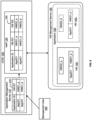
- Fig. 2 is a block diagram that illustrates the generation and association of identifiers for a virtual machine that is configured within a cloud-based application, according to one or more embodiments.
- application management server 110 has modeled therein one single VM cloud-based application. The modeling of the application is performed by management user 160 accessing application management server 110 (as was shown in Fig. 1 ).
- the elements that application management server 110 generates and stores when a cloud-based application is modeled and deployed are specific identifiers that pertain to the cloud-based application as a whole, and to individual virtual machines that are included in the cloud-based application.
- this metadata for the cloud-based application is stored within a data structure, such as table 225 illustrated in Fig. 2 .
- the metadata is stored in a file system that is accessible to application management server 110.
- application management server 110 When management user 160 models, saves, and deploys a cloud-based application using application management server 110, application management server 110 generates unique identifiers. For the embodiment illustrated in Fig. 2 , application management server 110 generates a unique application ID (referred to in the example depicted in Fig. 2 as AppID1), which is an identifier for the application as a whole. For example, if management user 160 models a database application that is to run and access an Oracle database, then application management server 110 generates a single application ID (e.g., AppID1) that corresponds to that database application. Thus, using application management server 110, a management user would be able to refer to or query any element of the database application using the generated application ID.
- AppID1 unique application ID
- application management server 110 when management user 160 models, saves, and deploys a cloud-based application using application management server 110, application management server 110 generates a unique identifier for each virtual machine that is a component of the cloud-based application. Referring to Fig. 2 , this unique identifier is identified as VM ID1. In the example illustrated in Fig. 2 , a single VM ID1 (i.e., VMID1_a) is generated for the cloud-based application identified by AppID1. Thus, the cloud-based application identified by AppID1 is a single-VM application, wherein the single VM defined for the application is identified in application management server 110 by VMID1_a.
- management user 160 may model a single-VM cloud-based database application, where the virtual machine is configured to run the Oracle database software as well as user defined application software.
- the database application as a whole is referred to by its unique application ID (i.e., AppID1), while only the virtual machine that is a part of the database application is referred to by its unique VM ID1 (i.e., VMID1_a).
- AppID1 unique application ID
- VMID1_a unique VM ID1
- management user 160 if management user 160 wishes to retrieve (using application management server 110) the status of all components of the application depicted in Fig. 2 (e.g., the virtual machine and any other virtual hardware elements, such as virtual switches and disks), management user 160 formulates and transmits a query from application management server 110 to the cloud, referring to AppID1.
- management 160 user wishes to retrieve (using application management server 110) the deployment status of only the single virtual machine in the application depicted in Fig. 2 , management user 160 formulates and transmits a query from application management server 110 to the cloud, referring to VMID1_a.
- application management server 110 communicates directly with IaaS 120.
- IaaS 120 communicates directly with VM management server 130.
- IaaS 120 provides a selection of predefined virtual machine types (or templates) that management user 160 may associate with the virtual machines modeled in application management server 110.
- application management server 110 transmits a deployment request to IaaS 120.
- IaaS 120 transmits one or more requests to VM management server 130 in order to instantiate the requested virtual machines.
- application management server 110 transmits a request to deploy the cloud-based application having an application ID, AppID1, and associated with a virtual machine having a VM ID1 identifier, VMID1_a, to IaaS 120.
- IaaS 120 receives the deployment request (which includes the application ID and the VM ID1 identifier), and transmits a request to VM management server 130 to instantiate the required virtual machine.
- IaaS 120 stores the application ID, AppID1, and the VM ID1 identifier, VMID1_a, as associated items in a data structure (e.g., table 230).
- table 230 in IaaS 120 includes another column so that AppID1 and VMID1_a can be associated with another yet to be identified VM.
- VM management server 130 receives virtual machine instantiation requests from IaaS 120 and, in response thereto, instantiates virtual machines within the cloud.
- VM 140 is instantiated in response to a request received from IaaS 120, which corresponds to the request IaaS 120 receives from application management server 110.
- VM 140 also contains metadata, which is either stored in virtual memory or on a virtual storage device that is configured as a part of VM 140.
- the metadata includes AppID1 and VMID1_a, which, as was mentioned previously, are the identifiers generated by application management server 110 when a cloud-based application is modeled therein.
- VMID2_a is a unique virtual machine identifier (referred to generally as VM ID2) that is generated by VM management server 130 when a virtual machine is instantiated therein.
- VM ID2 may be stored in the instantiated virtual machine.
- VM ID2 may be stored external to the virtual machine while being logically associated with the virtual machine.
- VMID2_a since VMID2_a is generated independently from AppID1 and VMID1_a, there remains the task to associate the identifiers generated by application management server 110 (i.e., AppID1 and VMID1_a) with the identifier generated by VM management server 130 (i.e., VMID2_a).
- VM management server 130 instantiates VM 140 and generates VMID2_a
- VM management server 130 transmits VMID2_a to IaaS 120.
- IaaS 120 receives VMID2_a from VM management server 130
- IaaS 120 stores VMID2_a in table 230 in a way so as to associate AppID1 and VMID1_a with VMID2_a.
- This storing of VMID2_a is illustrated conceptually in Fig. 2 by arrow 240 extending from VMID2_a within VM 140 to the null data field in table 230 within IaaS 120.
- VMID2_a is stored in table 230 of IaaS 120, then AppID1 and VMID1_a are associated with VMID2_a.
- an association is created between the application configured in application management server 110 (i.e., the application with application ID AppID1) and the virtual machine instantiated within VM management server 130 (i.e., VM 140).
- This association is illustrated conceptually by showing VM 140 as grouped within application 150.
- application 150 serves as a way of identifying a grouping of virtual machines instantiated in VM management server 130 within a single application having a single unique application identifier (e.g., AppID1).
- AppID1 application unique application identifier
- Fig. 3 is a flow diagram that illustrates a method 300 of deploying a multi-VM cloud-based application, according to one or more embodiments.
- Fig. 3 is described in conjunction with the block diagram of Fig. 4 .
- method 300 begins at step 310, where an application with one or more VMs is modeled. As previously mentioned, this is typically accomplished by a management user using application management server 110.
- application management server 110 has modeled therein a cloud-based application having three separate virtual machines.
- the first virtual machine may be a storage server
- the second virtual machine may be a security server
- the third virtual machine may be a publishing server.
- step 320 application management server 110 receives a request to deploy the modeled application to a cloud infrastructure.
- application management server 110 In response to receiving the deployment request at step 320, application management server 110 generates, at step 330, a unique application ID that corresponds to the modeled application.
- AppID1 (which is stored in table 225 within application management server 110) corresponds to the modeled application.
- step 340 a unique VM ID1 is generated for a next virtual machine that is modeled within the cloud-based application.
- a three-VM cloud based application is modeled in application management server 110.
- VMID1_a is generated and stored for the first of the three virtual machines.
- method 300 then proceeds to step 350, where the virtual machine whose VM ID1 has been generated at step 340 is deployed to (or instantiated in) the cloud.
- deployment of a VM to the cloud comprises transmitting a deployment request for the VM from application management server 110 to IaaS 120.
- the deployment request includes the generated application ID and VM ID1 (e.g., AppID1 and VMID1_a, from Fig. 4 ).
- IaaS 120 then transmits a further request to the cloud infrastructure (e.g., to VM management server 130) to instantiate a VM corresponding to the deployment request. As shown in Fig.
- IaaS 120 receives a deployment request for the first VM modeled in application management server 110 (i.e., the VM identified by VMID1_a). IaaS 120 stores AppID1 and VMID1_a in table 230, and transmits an instantiation request to VM management server 130 corresponding to the VM identified in application management server 110 by VMID1_a. VM management server 130 then instantiates a first virtual machine (i.e., VM 140 1 ). As shown in Fig. 4 , VM 140 1 stores metadata that includes AppID1 and VMID1_a. In addition, as a result of the instantiation of VM 140 1 , VM management server 130 generates VMID2_a, which is stored in (or is logically associated with) VM 140 1 .
- step 360 the generated VM ID2, which, as previously mentioned, is generated by the cloud (e.g., VM management server 130) when the cloud instantiates a VM, is received by IaaS 120 from the cloud.
- VM management server 130 transmits VMID2_a (which VM management server 130 generates at step 350) to IaaS 120.
- IaaS 120 associates VMID2_a received at step 360 with application ID AppID1 and VM ID1 VMID1_a, which are generated, respectively, in steps 330 and 340.
- IaaS 120 receives VMID2_a from VM management server 130 and stores it in the entry of table 230 that contains AppID1 and VMID1_a.
- AppID1 and VMID1_a which uniquely identify, from the perspective of application management server 110, the first modeled virtual machine
- VM 140 1 which is the corresponding virtual machine instantiated within VM management server 130.
- method 300 determines whether there are more VMs modeled as part of the cloud-based application in application management server 110. If there are more VMs, then method 300 proceeds back to step 340, where a next VM ID1 is generated for the next VM. Thus, referring to Fig. 4 , VMID1_b is generated for the second VM. Method 300 then proceeds through steps 350-370 to deploy the second VM to the cloud and to associate the deployed second VM with the second VM as modeled in application management server 110. As shown in Fig. 4 , VM management server 130 instantiates VM 140 2 and generates VMID2_b. AppID1 and VMID1_b are then associated with VMID2_b in the second entry of table 230. It should be noted that method 300 proceeds through steps 340-370 in like manner for the third virtual machine modeled in application management server 110 (i.e., the virtual machine identified by VMID1_c).
- method 300 determines that there are no more VMs modeled as part of the cloud-based application in application management server 110, then all application VMs are deployed and method 300 terminates.
- identifier for a virtual machine as generated by application management server 110 i.e., the Application ID and/or VM ID1
- the identifier generated by VM management server 130 for the same virtual machine when the virtual machine is deployed to the cloud (i.e., VM ID2).
- One benefit is the ability to track the progress of deployment of virtual machines directly from application management server 110.
- Another benefit is the ability to access an already-deployed virtual machine at a time well after its deployment in order to update or install new software on the virtual machine.
- the association between the Application ID and VM ID1 (as generated by application management server 110) with VM ID2 (as generated by VM management server 130) may be broken.
- Scaling a virtual machine refers to dynamically changing system parameters (such as the amount of available RAM, the number of available CPUs, and the like) of the virtual machine.
- a virtual machine may be scaled up or down using system administration tools that are operated independently of application management server 110. For example, a system administrator may perform administration tasks on cloud-based virtual machines using the VSphere suite of administration tools, which is commercially available from VMware, Inc.
- scaling a cloud-based virtual machine entails allocating a new virtual machine in the cloud with the required scaled up (or scaled down) parameters, copying the runtime state and data of the existing virtual machine to the newly scaled virtual machine, instantiating and starting the newly scaled virtual machine, and destroying (or deallocating) the previously existing virtual machine. In this way, the newly scaled virtual machine replaces the previously existing virtual machine.
- the association between the identifiers generated by application management server 110 (Application ID and VM ID1) and the identifier generated by VM management server 130 (VM ID2) is broken.
- the reason for this is due to the fact that when VM management server 130 creates the newly scaled virtual machine, a new VM ID2 is generated in the process.
- the VM ID2 of the previously existing virtual machine is not copied to or associated with the newly scaled virtual machine.
- the previously existing virtual machine is destroyed, along with the metadata for that virtual machine.
- the VM ID2 of the previously existing virtual machine no longer refers to an existing virtual machine.
- the application ID and VM ID1 of the previously existing virtual machine is stored persistently, in embodiments, in table 230 of IaaS 120, as well as in table 225 of application management server 110.
- application management server 110 maintains a unique handle to the applications and corresponding virtual machines that have been previously modeled and deployed. Therefore, it is possible to establish an association between the Application ID and VM ID1 of the virtual machines modeled in application management server 110 after such virtual machines are scaled up or down independently of application management server 110 (for example, when those virtual machines are newly scaled using VSphere administration tools).
- Fig. 5 is a flow diagram of a method 500 of scaling up a virtual machine in a cloud-based computing environment, according to one or more embodiments.
- Fig. 5 will be described in conjunction with Fig. 6 , which is a block diagram that illustrates conceptually the scaling up of a virtual machine in a cloud-based computing environment.
- VM 140 1 is a virtual machine instantiated in VM management server 130 as a result of a previous deployment of an application (identified in application management server 110 and IaaS 120 by application ID AppID1) with one virtual machine (identified in application management server 110 and IaaS 120 by VM ID1 VMID1_a).
- Method 500 begins at step 510, where a request to scale up a virtual machine is received.
- scaling request 610 is received by VM cloud administrator 600.
- VM cloud administrator 600 may, in embodiments, comprise the vSphere ® suite of administration tools available from VMware, Inc.
- request 610 is transmitted to VM cloud administrator 600 by a system administrator through, for example, a system console.
- Method 500 then proceeds to step 520, where, in response to the scaling request, a newly scaled up virtual machine is instantiated in the cloud.
- a newly scaled up virtual machine is instantiated in the cloud.
- This is illustrated in Fig. 6 by the creation (by VM cloud administrator 600 communicating with VM management server 130) of a new virtual machine VM 140 2 .
- VM 140 2 is created with scaled up system parameters in relation to previously instantiated and deployed VM 140 1 .
- the dotted outline of VM 140 2 denotes that VM 140 2 is newly created. It should be noted that when VM 140 2 is created, VM management server 130 generates VMID2_b, which is different from VMID2_a of VM 140 1 .
- step 530 the data of VM 140 1 is copied to VM 140 2 .
- this includes the metadata items AppID1 and VMID1_a.
- VMID2_a is not copied to or associated with VM 140 2 .
- step 540 the application ID and VM ID1 of the previously existing virtual machine are associated with VM ID2 of the newly scaled up VM.
- this association is performed via VM management server 130 communicating VMID2_b to IaaS 120.
- IaaS 120 which, prior to the scaling up of VM 140 1 , stored AppID1, VMID1_a, and VMID2_a as associated data elements in table 230, stores VMID2_bin the entry of table 230 corresponding to AppID1 and VMID1_a.
- VM 140 2 is depicted in Fig. 6 as being grouped within VM management server 130 as part of application 150, which, as previously mentioned, corresponds to the application identified in application management server 110 by AppID1.
- step 550 the previously existing virtual machine (i.e., VM 140 1 ) is deallocated. After step 550, method 500 terminates.
- cloud-based applications may be “scaled in” or “scaled out.”
- Scaling in a cloud-based application refers to removing some virtual machines from the application while continuing to execute the application within the cloud.
- Scaling out a cloud-based application refers to adding virtual machines to the application while the application executes in the cloud.
- scaling up and scaling down a virtual machine is typically performed by accessing a system administration tool that is independent of application management server 110 (such as VM cloud administrator 600)
- scaling a cloud-based application either in or out is performed by a management user (such as management user 160 of Fig. 1 ) that accesses application management server 110.
- Fig. 7 is a flow diagram that illustrates a method 700 for scaling out a virtualized cloud-based application, according to one or more embodiments.
- Fig. 7 is described herein in conjunction with Fig. 8 , which is a block diagram that depicts the scaling out of a single-VM cloud-based application to a dual-VM cloud-based application.
- management user 160 accesses application management server 110, which has modeled therein a single-VM application previously deployed to VM management server 130.
- the deployed application is identified by application ID AppID1 and the first VM is identified by VMID1_a.
- table 230 of IaaS 120 associates AppID1 and VMID1_a with VMID2_a, which is the VM ID2 of previously deployed virtual machine VM 140 1 .
- Method 700 begins at step 710, where application management server 110 receives a request to scale out the application identified in Fig. 8 by AppID1.
- the scale out request is for the addition of one virtual machine to the cloud-based application.
- any number of virtual machines may be added in a single request.
- such a request is received, in embodiments, from management user 160.
- step 720 application management server 110 generates a new VM ID1 for the newly requested virtual machine.
- application management server 110 generates VMID1_b for the new virtual machine, which corresponds to AppID1.
- the new virtual machine is deployed to the cloud.
- application management server 110 transmits a deployment request for a virtual machine to IaaS 120, which, in turn, transmits a request to VM management server 130 (i.e., the cloud infrastructure).
- VM management server 130 i.e., the cloud infrastructure
- IaaS 120 stores AppID1 and VMID1_b as associated data elements in table 230.
- IaaS 120 transmits a request to VM management server 130 to instantiate the new virtual machine the cloud.
- VM management server 130 instantiates VM 140 2 , generating VMID2_b in the process. Note that AppID1 and VMID1_b are included in the metadata of newly instantiated VM 140 2 .
- step 740 IaaS 120 receives from VM management server 130 VMID2_b of newly instantiated VM 140 2 .
- step 750 IaaS 120 associates AppID1 and VMID1_b (which are both generated by application management server 110) with VMID2_b (which is generated by VM management server 130).
- VMID2_b which is generated by VM management server 130.
- IaaS 120 makes this association by storing VMID2_b in the entry of table 230 that associates AppID1 with VMID1_b.
- management user 160 may access VM 140 2 from application management server 110. This is useful should management user 160 wish to install software on VM 140 2 from application management server 110 at a later point in time.
- the various embodiments described herein may employ various computer-implemented operations involving data stored in computer systems. For example, these operations may require physical manipulation of physical quantities-usually, though not necessarily, these quantities may take the form of electrical or magnetic signals, where they or representations of them are capable of being stored, transferred, combined, compared, or otherwise manipulated. Further, such manipulations are often referred to in terms, such as producing, yielding, identifying, determining, or comparing. Any operations described herein that form part of one or more embodiments of the disclosure may be useful machine operations. In addition, one or more embodiments of the disclosure also relate to a device or an apparatus for performing these operations.
- the apparatus may be specially constructed for specific required purposes, or it may be a general purpose computer selectively activated or configured by a computer program stored in the computer.
- various general purpose machines may be used with computer programs written in accordance with the teachings herein, or it may be more convenient to construct a more specialized apparatus to perform the required operations.
- One or more embodiments of the present disclosure may be implemented as one or more computer programs or as one or more computer program modules embodied in one or more computer readable media.
- the term computer readable medium refers to any data storage device that can store data which can thereafter be input to a computer system-computer readable media may be based on any existing or subsequently developed technology for embodying computer programs in a manner that enables them to be read by a computer.
- Examples of a computer readable medium include a hard drive, network attached storage (NAS), read-only memory, random-access memory (e.g., a flash memory device), a CD (Compact Discs) --CD-ROM, a CD-R, or a CD-RW, a DVD (Digital Versatile Disc), a magnetic tape, and other optical and non-optical data storage devices.
- the computer readable medium can also be distributed over a network coupled computer system so that the computer readable code is stored and executed in a distributed fashion.
Landscapes
- Engineering & Computer Science (AREA)
- Software Systems (AREA)
- Theoretical Computer Science (AREA)
- General Engineering & Computer Science (AREA)
- Physics & Mathematics (AREA)
- General Physics & Mathematics (AREA)
- Computer Security & Cryptography (AREA)
- Stored Programmes (AREA)
Claims (11)
- Procédé de déploiement, par un système informatique virtualisé comprenant un serveur de gestion de machines virtuelles (130) et un serveur de gestion d'application (110), d'une application (150) dans un environnement informatique en nuage (100) comprenant une pluralité de machines virtuelles (1401-140n) gérées par le serveur de gestion de machines virtuelles (130), l'application (150) étant exécutée en utilisant une pluralité des machines virtuelles (1401-140n) incluant une première machine virtuelle (1401), le procédé comprenant les étapes consistant à :
par l'intermédiaire du serveur de gestion d'application (110) dans lequel l'application (150) est modélisée avant un déploiement :générer un identifiant d'application unique (AppID1) qui est un identifiant pour l'application (150) dans son ensemble ;générer un premier identifiant de machine virtuelle unique (VMID1) pour la première machine virtuelle (1401),dans lequel le premier identifiant de machine virtuelle unique (VMID1) identifie la première machine virtuelle (1401) comme faisant partie de l'application (150) ;envoyer des instructions au serveur de gestion de machines virtuelles (130) pour déployer l'application (150) ;par l'intermédiaire du serveur de gestion de machines virtuelles (130) :recevoir les instructions pour déployer l'application (150) ;instancier la première machine virtuelle (1401) dans le serveur de gestion de machines virtuelles (130) ;générer un second identifiant de machine virtuelle unique (VMID2) indépendamment de l'identifiant d'application unique (AppID1) et du premier identifiant de machine virtuelle unique (VMID1) lorsqu'en réponse à une demande d'instanciation de machine virtuelle, la première machine virtuelle (1401) est instanciée dans le serveur de gestion de machines virtuelles (130) ; etcréer une association entre l'identifiant d'application unique (AppID1), le premier identifiant de machine virtuelle unique (VMID1) et le second identifiant de machine virtuelle unique (VMID2), en créant ainsi une association entre l'application (150) configurée dans le serveur de gestion d'application (110) et la première machine virtuelle (1401) instanciée dans le serveur de gestion de machines virtuelles (130) ;par l'intermédiaire du serveur de gestion d'application (110) :
accéder à la première machine virtuelle (1401) en utilisant le second identifiant de machine virtuelle unique (VMID2). - Procédé selon la revendication 1, dans lequel l'identifiant d'application unique (AppID1) et le premier identifiant de machine virtuelle unique (VMID1) sont stockés dans des métadonnées associées à la première machine virtuelle (1401).
- Procédé selon la revendication 1, dans lequel l'identifiant d'application unique (AppID1) et le premier identifiant de machine virtuelle unique (VMID1) sont générés par un premier composant de logiciel s'exécutant sur le serveur de gestion d'application (110), et le second identifiant de machine virtuelle unique (VMID2) est généré par un second composant de logiciel (120) s'exécutant dans le serveur de gestion de machines virtuelles (130).
- Procédé selon la revendication 3, dans lequel le premier composant de logiciel s'exécutant sur le serveur de gestion d'application (110) comprend un premier module qui génère un plan de déploiement pour l'application et un second module qui fournit une sélection de modèles de machine virtuelle pour l'application, et dans lequel l'identifiant d'application unique (AppID1) est généré par le premier module.
- Procédé selon la revendication 4, dans lequel l'association entre l'identifiant d'application unique (AppID1), le premier identifiant de machine virtuelle unique (VMID1) et le second identifiant de machine virtuelle unique (VMID2) est stockée dans une structure de données (230) qui est accessible au second module du serveur de gestion d'application (110).
- Procédé selon la revendication 5, comprenant en outre les étapes consistant à :recevoir, par l'intermédiaire du premier composant de logiciel s'exécutant sur le serveur de gestion d'applications (110), une demande de mise à jour du logiciel de la première machine virtuelle (1401) ;localiser le premier identifiant de machine virtuelle unique (VMID1) dans la structure de données (230) ;accéder au second identifiant de machine virtuelle unique (VMID2) sur la base du premier identifiant de machine virtuelle unique (VMID1) ; ettransmettre la mise à jour de logiciel pour la première machine virtuelle (1401) en utilisant le second identifiant de machine virtuelle unique (VMID2).
- Procédé selon la revendication 3, comprenant en outre les étapes consistant à :recevoir, par l'intermédiaire du second composant de logiciel s'exécutant dans le serveur de gestion de machines virtuelles (130), une demande de mise à l'échelle de la première machine virtuelle (1401) ;instancier dans le serveur de gestion de machines virtuelles (130) une seconde machine virtuelle (1402) qui est une version mise à l'échelle de la première machine virtuelle (1401) ;générer, par l'intermédiaire du second composant de logiciel s'exécutant dans le serveur de gestion de machines virtuelles (130), un nouvel identifiant de machine virtuelle unique (VMID2_b) qui correspond à la seconde machine virtuelle (1402) et qui est différent du second identifiant de machine virtuelle unique (VMID2) ;associer l'identifiant d'application unique (AppID1) et le premier identifiant de machine virtuelle unique (VMID1) au nouvel identifiant de machine virtuelle unique (VMID2_b) ; etaprès association de l'identifiant d'application unique (AppID1) et du premier identifiant de machine virtuelle unique (VMID1) avec le nouvel identifiant de machine virtuelle unique (VMID2_b), désallouer la première machine virtuelle (1401).
- Procédé selon la revendication 3, comprenant en outre les étapes consistant à :recevoir, par l'intermédiaire du premier composant de logiciel s'exécutant dans le serveur de gestion d'application (110), une demande de déploiement d'une seconde machine virtuelle pour l'application ;générer un premier identifiant de machine virtuelle unique (VMID1_b) pour la seconde machine virtuelle ;instancier la seconde machine virtuelle (1402) dans le serveur de gestion de machines virtuelles (130) ;générer un second identifiant de machine virtuelle unique (VMID2_b) pour la seconde machine virtuelle (1402) ; etcréer une association entre l'identifiant d'application unique (AppID1), le premier identifiant de machine virtuelle unique (VMID1_b) de la seconde machine virtuelle (1402), et le second identifiant de machine virtuelle unique (VMID2_b) de la seconde machine virtuelle (1402).
- Procédé selon la revendication 1, dans lequel le serveur de gestion d'application (110) et le serveur de gestion de machines virtuelles (130) s'exécutent sur le même serveur physique.
- Support lisible par ordinateur non transitoire comprenant des instructions exécutables par un ou plusieurs hôtes dans un environnement informatique virtualisé, où les instructions, lorsqu'elles sont exécutées, amènent les un ou plusieurs hôtes à exécuter un procédé selon l'une quelconque des revendications 1 à 9.
- Système informatique configuré pour exécuter le procédé selon l'une quelconque des revendications 1 à 9.
Applications Claiming Priority (2)
| Application Number | Priority Date | Filing Date | Title |
|---|---|---|---|
| US14/287,366 US20150347170A1 (en) | 2014-05-27 | 2014-05-27 | Grouping virtual machines in a cloud application |
| PCT/US2015/032625 WO2015183919A1 (fr) | 2014-05-27 | 2015-05-27 | Regroupement de machines virtuelles dans une application en nuage |
Publications (4)
| Publication Number | Publication Date |
|---|---|
| EP3149578A1 EP3149578A1 (fr) | 2017-04-05 |
| EP3149578A4 EP3149578A4 (fr) | 2018-03-14 |
| EP3149578B1 true EP3149578B1 (fr) | 2024-11-27 |
| EP3149578C0 EP3149578C0 (fr) | 2024-11-27 |
Family
ID=54699694
Family Applications (1)
| Application Number | Title | Priority Date | Filing Date |
|---|---|---|---|
| EP15800625.4A Active EP3149578B1 (fr) | 2014-05-27 | 2015-05-27 | Regroupement de machines virtuelles dans une application en nuage |
Country Status (4)
| Country | Link |
|---|---|
| US (1) | US20150347170A1 (fr) |
| EP (1) | EP3149578B1 (fr) |
| CN (1) | CN106663023B (fr) |
| WO (1) | WO2015183919A1 (fr) |
Families Citing this family (11)
| Publication number | Priority date | Publication date | Assignee | Title |
|---|---|---|---|---|
| KR20160091663A (ko) * | 2015-01-26 | 2016-08-03 | 삼성전자주식회사 | 멀티 플랫폼 기반의 어플리케이션 실행 방법 및 장치 |
| US10289398B2 (en) * | 2015-09-26 | 2019-05-14 | Cisco Technology, Inc. | In-service upgrade of kernel loadable modules |
| US10261782B2 (en) * | 2015-12-18 | 2019-04-16 | Amazon Technologies, Inc. | Software container registry service |
| US10666443B2 (en) * | 2016-10-18 | 2020-05-26 | Red Hat, Inc. | Continued verification and monitoring of application code in containerized execution environment |
| CN108733449B (zh) * | 2017-04-17 | 2022-01-25 | 伊姆西Ip控股有限责任公司 | 用于管理虚拟机的方法、设备和计算机可读存储介质 |
| CN107748749A (zh) * | 2017-08-18 | 2018-03-02 | 平安科技(深圳)有限公司 | 一种内存数据的更新方法、终端、设备以及可读存储介质 |
| US10917496B2 (en) * | 2017-09-05 | 2021-02-09 | Amazon Technologies, Inc. | Networked storage architecture |
| WO2019056187A1 (fr) * | 2017-09-19 | 2019-03-28 | 华为技术有限公司 | Système, appareil et procédé de déploiement d'applications |
| KR102090561B1 (ko) * | 2018-05-24 | 2020-03-18 | 주식회사 티맥스소프트 | 클라우드 환경에서 웹 서버와 was를 오토 스케일하는 방법 및 이를 사용한 was 관리자 서버 |
| CN111163060B (zh) * | 2019-12-11 | 2021-12-24 | 中盈优创资讯科技有限公司 | 一种基于应用组的转发方法、设备以及系统 |
| CN115509676A (zh) * | 2021-06-22 | 2022-12-23 | 华为云计算技术有限公司 | 一种容器集的部署方法及装置 |
Citations (2)
| Publication number | Priority date | Publication date | Assignee | Title |
|---|---|---|---|---|
| US20080163171A1 (en) * | 2007-01-02 | 2008-07-03 | David Michael Chess | Virtual resource templates |
| US20140137111A1 (en) * | 2012-11-15 | 2014-05-15 | Bank Of America Corporation | Host naming application programming interface |
Family Cites Families (10)
| Publication number | Priority date | Publication date | Assignee | Title |
|---|---|---|---|---|
| US4975836A (en) * | 1984-12-19 | 1990-12-04 | Hitachi, Ltd. | Virtual computer system |
| US8732699B1 (en) * | 2006-10-27 | 2014-05-20 | Hewlett-Packard Development Company, L.P. | Migrating virtual machines between physical machines in a define group |
| US20080250407A1 (en) * | 2007-04-05 | 2008-10-09 | Microsoft Corporation | Network group name for virtual machines |
| US8161479B2 (en) * | 2008-06-13 | 2012-04-17 | Microsoft Corporation | Synchronizing virtual machine and application life cycles |
| KR101122962B1 (ko) * | 2010-08-04 | 2012-03-16 | 삼성에스디에스 주식회사 | 사용자 단말장치 및 멀티 가상머신 전환 방법 |
| CN102681899B (zh) * | 2011-03-14 | 2015-06-10 | 金剑 | 云计算服务平台的虚拟计算资源动态管理方法 |
| US9058198B2 (en) * | 2012-02-29 | 2015-06-16 | Red Hat Inc. | System resource sharing in a multi-tenant platform-as-a-service environment in a cloud computing system |
| US20130325885A1 (en) * | 2012-05-30 | 2013-12-05 | Red Hat Israel, Inc. | Provisioning composite applications using a hierarchical data structures |
| EP2687982A1 (fr) * | 2012-07-16 | 2014-01-22 | NTT DoCoMo, Inc. | Système hiérarchique permettant de gérer plusieurs machines virtuelles, procédé et programme informatique |
| CN103797462B (zh) * | 2013-10-23 | 2016-06-29 | 华为技术有限公司 | 一种创建虚拟机的方法和装置 |
-
2014
- 2014-05-27 US US14/287,366 patent/US20150347170A1/en not_active Abandoned
-
2015
- 2015-05-27 WO PCT/US2015/032625 patent/WO2015183919A1/fr not_active Ceased
- 2015-05-27 CN CN201580035775.5A patent/CN106663023B/zh active Active
- 2015-05-27 EP EP15800625.4A patent/EP3149578B1/fr active Active
Patent Citations (2)
| Publication number | Priority date | Publication date | Assignee | Title |
|---|---|---|---|---|
| US20080163171A1 (en) * | 2007-01-02 | 2008-07-03 | David Michael Chess | Virtual resource templates |
| US20140137111A1 (en) * | 2012-11-15 | 2014-05-15 | Bank Of America Corporation | Host naming application programming interface |
Also Published As
| Publication number | Publication date |
|---|---|
| EP3149578A4 (fr) | 2018-03-14 |
| US20150347170A1 (en) | 2015-12-03 |
| EP3149578C0 (fr) | 2024-11-27 |
| EP3149578A1 (fr) | 2017-04-05 |
| WO2015183919A1 (fr) | 2015-12-03 |
| CN106663023A (zh) | 2017-05-10 |
| CN106663023B (zh) | 2018-06-19 |
Similar Documents
| Publication | Publication Date | Title |
|---|---|---|
| US20150347170A1 (en) | Grouping virtual machines in a cloud application | |
| US11855904B2 (en) | Automated migration of compute instances to isolated virtual networks | |
| US9712604B2 (en) | Customized configuration of cloud-based applications prior to deployment | |
| US11487591B1 (en) | Automatically configuring execution of a containerized application | |
| US9871851B2 (en) | Migrating private infrastructure services to a cloud | |
| US12498988B2 (en) | Migrating stateful workloads between container clusters with different storage backends | |
| Fifield et al. | OpenStack Operations Guide: Set up and manage your openstack cloud | |
| US9639691B2 (en) | Dynamic database and API-accessible credentials data store | |
| US10721121B2 (en) | Methods for synchronizing configurations between computing systems using human computer interfaces | |
| EP3149603B1 (fr) | Configuration personnalisée d'applications en nuage avant un déploiement | |
| US20170371641A1 (en) | Multi-tenant upgrading | |
| US12495024B2 (en) | Computing cluster bring-up on any one of a plurality of different public cloud infrastructures | |
| US11023264B2 (en) | Blueprint application storage policy | |
| US20170161042A1 (en) | Deployment of processing components of computing infrastructure using annotated command objects | |
| EP4172773A1 (fr) | Service de plan de commande géré | |
| US11263053B2 (en) | Tag assisted cloud resource identification for onboarding and application blueprint construction | |
| US11900172B2 (en) | Computing cluster bring-up on public cloud infrastructure using expressed intents | |
| US10776148B1 (en) | System and method for utilizing computational power of a server farm | |
| US11546220B2 (en) | Systems and methods for optimizing the number of servers in a cluster | |
| US11924336B1 (en) | Cryptographic artifact generation using virtualized security modules | |
| US20150372945A1 (en) | Mapping computer resources to consumers in a computer system | |
| US11860819B1 (en) | Auto-generation of partition key | |
| US12625722B2 (en) | Semantic-aware workflow modification and execution with extraction of missing parameter | |
| Finta | Mitigating the effects of vendor lock-in in edge cloud environments with open-source technologies | |
| US20250335325A1 (en) | Selection and configuration of input-output software tools for execution of input-output workloads |
Legal Events
| Date | Code | Title | Description |
|---|---|---|---|
| STAA | Information on the status of an ep patent application or granted ep patent |
Free format text: STATUS: THE INTERNATIONAL PUBLICATION HAS BEEN MADE |
|
| PUAI | Public reference made under article 153(3) epc to a published international application that has entered the european phase |
Free format text: ORIGINAL CODE: 0009012 |
|
| STAA | Information on the status of an ep patent application or granted ep patent |
Free format text: STATUS: REQUEST FOR EXAMINATION WAS MADE |
|
| 17P | Request for examination filed |
Effective date: 20160914 |
|
| AK | Designated contracting states |
Kind code of ref document: A1 Designated state(s): AL AT BE BG CH CY CZ DE DK EE ES FI FR GB GR HR HU IE IS IT LI LT LU LV MC MK MT NL NO PL PT RO RS SE SI SK SM TR |
|
| AX | Request for extension of the european patent |
Extension state: BA ME |
|
| DAV | Request for validation of the european patent (deleted) | ||
| DAX | Request for extension of the european patent (deleted) | ||
| A4 | Supplementary search report drawn up and despatched |
Effective date: 20180208 |
|
| RIC1 | Information provided on ipc code assigned before grant |
Ipc: G06F 9/455 20180101AFI20180202BHEP Ipc: G06F 15/16 20060101ALI20180202BHEP |
|
| STAA | Information on the status of an ep patent application or granted ep patent |
Free format text: STATUS: EXAMINATION IS IN PROGRESS |
|
| 17Q | First examination report despatched |
Effective date: 20181213 |
|
| RAP3 | Party data changed (applicant data changed or rights of an application transferred) |
Owner name: VMWARE LLC |
|
| GRAP | Despatch of communication of intention to grant a patent |
Free format text: ORIGINAL CODE: EPIDOSNIGR1 |
|
| STAA | Information on the status of an ep patent application or granted ep patent |
Free format text: STATUS: GRANT OF PATENT IS INTENDED |
|
| INTG | Intention to grant announced |
Effective date: 20240816 |
|
| GRAS | Grant fee paid |
Free format text: ORIGINAL CODE: EPIDOSNIGR3 |
|
| GRAA | (expected) grant |
Free format text: ORIGINAL CODE: 0009210 |
|
| STAA | Information on the status of an ep patent application or granted ep patent |
Free format text: STATUS: THE PATENT HAS BEEN GRANTED |
|
| AK | Designated contracting states |
Kind code of ref document: B1 Designated state(s): AL AT BE BG CH CY CZ DE DK EE ES FI FR GB GR HR HU IE IS IT LI LT LU LV MC MK MT NL NO PL PT RO RS SE SI SK SM TR |
|
| REG | Reference to a national code |
Ref country code: GB Ref legal event code: FG4D |
|
| REG | Reference to a national code |
Ref country code: CH Ref legal event code: EP |
|
| REG | Reference to a national code |
Ref country code: DE Ref legal event code: R096 Ref document number: 602015090510 Country of ref document: DE |
|
| REG | Reference to a national code |
Ref country code: IE Ref legal event code: FG4D |
|
| U01 | Request for unitary effect filed |
Effective date: 20241223 |
|
| U07 | Unitary effect registered |
Designated state(s): AT BE BG DE DK EE FI FR IT LT LU LV MT NL PT RO SE SI Effective date: 20250114 |
|
| PG25 | Lapsed in a contracting state [announced via postgrant information from national office to epo] |
Ref country code: IS Free format text: LAPSE BECAUSE OF FAILURE TO SUBMIT A TRANSLATION OF THE DESCRIPTION OR TO PAY THE FEE WITHIN THE PRESCRIBED TIME-LIMIT Effective date: 20250327 Ref country code: HR Free format text: LAPSE BECAUSE OF FAILURE TO SUBMIT A TRANSLATION OF THE DESCRIPTION OR TO PAY THE FEE WITHIN THE PRESCRIBED TIME-LIMIT Effective date: 20241127 |
|
| PG25 | Lapsed in a contracting state [announced via postgrant information from national office to epo] |
Ref country code: ES Free format text: LAPSE BECAUSE OF FAILURE TO SUBMIT A TRANSLATION OF THE DESCRIPTION OR TO PAY THE FEE WITHIN THE PRESCRIBED TIME-LIMIT Effective date: 20241127 |
|
| PG25 | Lapsed in a contracting state [announced via postgrant information from national office to epo] |
Ref country code: NO Free format text: LAPSE BECAUSE OF FAILURE TO SUBMIT A TRANSLATION OF THE DESCRIPTION OR TO PAY THE FEE WITHIN THE PRESCRIBED TIME-LIMIT Effective date: 20250227 |
|
| PG25 | Lapsed in a contracting state [announced via postgrant information from national office to epo] |
Ref country code: GR Free format text: LAPSE BECAUSE OF FAILURE TO SUBMIT A TRANSLATION OF THE DESCRIPTION OR TO PAY THE FEE WITHIN THE PRESCRIBED TIME-LIMIT Effective date: 20250228 |
|
| PG25 | Lapsed in a contracting state [announced via postgrant information from national office to epo] |
Ref country code: PL Free format text: LAPSE BECAUSE OF FAILURE TO SUBMIT A TRANSLATION OF THE DESCRIPTION OR TO PAY THE FEE WITHIN THE PRESCRIBED TIME-LIMIT Effective date: 20241127 |
|
| PG25 | Lapsed in a contracting state [announced via postgrant information from national office to epo] |
Ref country code: RS Free format text: LAPSE BECAUSE OF FAILURE TO SUBMIT A TRANSLATION OF THE DESCRIPTION OR TO PAY THE FEE WITHIN THE PRESCRIBED TIME-LIMIT Effective date: 20250227 |
|
| RAP4 | Party data changed (patent owner data changed or rights of a patent transferred) |
Owner name: VMWARE LLC |
|
| U1H | Name or address of the proprietor changed after the registration of the unitary effect |
Owner name: VMWARE LLC; US |
|
| U20 | Renewal fee for the european patent with unitary effect paid |
Year of fee payment: 11 Effective date: 20250423 |
|
| PG25 | Lapsed in a contracting state [announced via postgrant information from national office to epo] |
Ref country code: SM Free format text: LAPSE BECAUSE OF FAILURE TO SUBMIT A TRANSLATION OF THE DESCRIPTION OR TO PAY THE FEE WITHIN THE PRESCRIBED TIME-LIMIT Effective date: 20241127 |
|
| PG25 | Lapsed in a contracting state [announced via postgrant information from national office to epo] |
Ref country code: SK Free format text: LAPSE BECAUSE OF FAILURE TO SUBMIT A TRANSLATION OF THE DESCRIPTION OR TO PAY THE FEE WITHIN THE PRESCRIBED TIME-LIMIT Effective date: 20241127 |
|
| PG25 | Lapsed in a contracting state [announced via postgrant information from national office to epo] |
Ref country code: CZ Free format text: LAPSE BECAUSE OF FAILURE TO SUBMIT A TRANSLATION OF THE DESCRIPTION OR TO PAY THE FEE WITHIN THE PRESCRIBED TIME-LIMIT Effective date: 20241127 |
|
| PLBE | No opposition filed within time limit |
Free format text: ORIGINAL CODE: 0009261 |
|
| STAA | Information on the status of an ep patent application or granted ep patent |
Free format text: STATUS: NO OPPOSITION FILED WITHIN TIME LIMIT |
|
| REG | Reference to a national code |
Ref country code: CH Ref legal event code: L10 Free format text: ST27 STATUS EVENT CODE: U-0-0-L10-L00 (AS PROVIDED BY THE NATIONAL OFFICE) Effective date: 20251008 |
|
| 26N | No opposition filed |
Effective date: 20250828 |
|
| REG | Reference to a national code |
Ref country code: CH Ref legal event code: H13 Free format text: ST27 STATUS EVENT CODE: U-0-0-H10-H13 (AS PROVIDED BY THE NATIONAL OFFICE) Effective date: 20251223 |
|
| PG25 | Lapsed in a contracting state [announced via postgrant information from national office to epo] |
Ref country code: CH Free format text: LAPSE BECAUSE OF NON-PAYMENT OF DUE FEES Effective date: 20250531 |
|
| GBPC | Gb: european patent ceased through non-payment of renewal fee |
Effective date: 20250527 |
|
| PG25 | Lapsed in a contracting state [announced via postgrant information from national office to epo] |
Ref country code: MC Free format text: LAPSE BECAUSE OF FAILURE TO SUBMIT A TRANSLATION OF THE DESCRIPTION OR TO PAY THE FEE WITHIN THE PRESCRIBED TIME-LIMIT Effective date: 20241127 |
|
| PG25 | Lapsed in a contracting state [announced via postgrant information from national office to epo] |
Ref country code: GB Free format text: LAPSE BECAUSE OF NON-PAYMENT OF DUE FEES Effective date: 20250527 |
|
| PG25 | Lapsed in a contracting state [announced via postgrant information from national office to epo] |
Ref country code: IE Free format text: LAPSE BECAUSE OF NON-PAYMENT OF DUE FEES Effective date: 20250527 |