EP3149698B1 - Procédé et système de géo-alignement d'images - Google Patents
Procédé et système de géo-alignement d'images Download PDFInfo
- Publication number
- EP3149698B1 EP3149698B1 EP15799568.9A EP15799568A EP3149698B1 EP 3149698 B1 EP3149698 B1 EP 3149698B1 EP 15799568 A EP15799568 A EP 15799568A EP 3149698 B1 EP3149698 B1 EP 3149698B1
- Authority
- EP
- European Patent Office
- Prior art keywords
- image
- sensor
- model
- imaging
- scene
- Prior art date
- Legal status (The legal status is an assumption and is not a legal conclusion. Google has not performed a legal analysis and makes no representation as to the accuracy of the status listed.)
- Active
Links
Images

Classifications
-
- G—PHYSICS
- G06—COMPUTING OR CALCULATING; COUNTING
- G06T—IMAGE DATA PROCESSING OR GENERATION, IN GENERAL
- G06T7/00—Image analysis
- G06T7/70—Determining position or orientation of objects or cameras
- G06T7/73—Determining position or orientation of objects or cameras using feature-based methods
- G06T7/75—Determining position or orientation of objects or cameras using feature-based methods involving models
-
- G—PHYSICS
- G06—COMPUTING OR CALCULATING; COUNTING
- G06F—ELECTRIC DIGITAL DATA PROCESSING
- G06F18/00—Pattern recognition
- G06F18/20—Analysing
- G06F18/22—Matching criteria, e.g. proximity measures
-
- G—PHYSICS
- G06—COMPUTING OR CALCULATING; COUNTING
- G06T—IMAGE DATA PROCESSING OR GENERATION, IN GENERAL
- G06T11/00—Two-dimensional [2D] image generation
- G06T11/60—Creating or editing images; Combining images with text
-
- G—PHYSICS
- G06—COMPUTING OR CALCULATING; COUNTING
- G06T—IMAGE DATA PROCESSING OR GENERATION, IN GENERAL
- G06T11/00—Two-dimensional [2D] image generation
- G06T11/60—Creating or editing images; Combining images with text
- G06T11/65—Creating or editing images; Combining images with text on geographic maps
-
- G—PHYSICS
- G06—COMPUTING OR CALCULATING; COUNTING
- G06T—IMAGE DATA PROCESSING OR GENERATION, IN GENERAL
- G06T17/00—Three-dimensional [3D] modelling for computer graphics
- G06T17/05—Geographic models
-
- G—PHYSICS
- G06—COMPUTING OR CALCULATING; COUNTING
- G06T—IMAGE DATA PROCESSING OR GENERATION, IN GENERAL
- G06T19/00—Manipulating three-dimensional [3D] models or images for computer graphics
- G06T19/006—Mixed reality
-
- G—PHYSICS
- G06—COMPUTING OR CALCULATING; COUNTING
- G06T—IMAGE DATA PROCESSING OR GENERATION, IN GENERAL
- G06T7/00—Image analysis
- G06T7/30—Determination of transform parameters for the alignment of images, i.e. image registration
- G06T7/33—Determination of transform parameters for the alignment of images, i.e. image registration using feature-based methods
- G06T7/344—Determination of transform parameters for the alignment of images, i.e. image registration using feature-based methods involving models
-
- G—PHYSICS
- G06—COMPUTING OR CALCULATING; COUNTING
- G06T—IMAGE DATA PROCESSING OR GENERATION, IN GENERAL
- G06T2207/00—Indexing scheme for image analysis or image enhancement
- G06T2207/30—Subject of image; Context of image processing
- G06T2207/30244—Camera pose
Definitions
- the present invention generally relates to georegistration, image processing, and augmented reality.
- Augmented reality involves enhancing the perception of a real world environment with supplementary visual and/or audio content, where artificial information is overlaid onto a view of a physical environment.
- the supplementary content may be projected onto a personalized display device, which may be specifically adapted for AR use, such as a head-mounted display (HMD) or AR-supporting eyeglasses or contact lenses, or alternatively the display screen of a mobile computing device (e.g., a smartphone or tablet computer).
- HMD head-mounted display
- AR-supporting eyeglasses or contact lenses or alternatively the display screen of a mobile computing device (e.g., a smartphone or tablet computer).
- the supplementary content is typically presented in real-time and in the context of elements in the current environment.
- AR is increasingly utilized in a wide variety of fields, ranging from: medicine (e.g., enhancing X-ray, ultrasound or endoscopic images of the interior of a human body to assist therapeutic and diagnostic procedures); commerce (e.g., allowing a customer to view the inside of a packaged product without opening it); and education (e.g., superimposing relevant educational material to enhance student comprehension); to: military (e.g., providing combat troops with relevant target information and indications of potential dangers); entertainment (e.g., augmenting a broadcast of a sporting event or theatre performance); and tourism (e.g., providing relevant information associated with a particular location or recreating simulations of historical events).
- medicine e.g., enhancing X-ray, ultrasound or endoscopic images of the interior of a human body to assist therapeutic and diagnostic procedures
- commerce e.g., allowing a customer to view the inside of a packaged product without opening it
- education e.g., superimposing relevant educational material to enhance student comprehension
- military e.g., providing
- an image of the environment captured by a camera or image sensor may be utilized, as well as telemetric data obtained from detectors or measurement systems, such as location or orientation determining systems, associated with the camera.
- a given camera includes various optics having particular imaging characteristics, such as the optical resolution, field of view, and focal length. These characteristics ultimately influence the parameters of the images acquired by that camera, as does the position and viewing angle of the camera with respect to the imaged scene.
- the measurement systems are inherently capable of supplying a certain level of accuracy or precision, but ultimately have limitations arising from the inherent precision of the various components.
- Such limitations may also vary depending on the particular environmental conditions (e.g., measurement accuracy may be lower during nighttime, rain or snow, or inclement weather), and may exacerbate over time due to gradual degradation of the optics and other system components.
- the position and orientation of the camera as acquired via the associated measurement systems may not correspond exactly to the real or true position and orientation of the camera.
- Such inaccuracies could be detrimental when attempting to georegister image data for displaying AR content, as it can lead to the AR content being superimposed out of context or at an incorrect relative position with respect to the relevant environmental features or elements.
- PCT Patent Application No. WO 2012/004622 to Piraud entitled “An Augmented Reality Method and a Corresponding System and Software", is directed to an augmented reality method and system for mobile terminals that involves overlaying location specific virtual information into the real images of the camera of the mobile terminal.
- the virtual information and also visual information about the environment at the location of the terminal is selected and downloaded from a remote database server, using as well the location (via GPS) and the orientation (via magnetometer, compass and accelerometer) of the mobile terminal.
- This information is continuously updated by measuring the movement of the mobile terminal and by predicting the real image content.
- the outline of the captured scene i.e., crest lines of mountains in the real camera images
- U.S. Patent Application No. 2010/0110069 to Yuan entitled “System for Rendering Virtual See-Through Scenes", is directed to a system and method for displaying an image on a display.
- a three-dimensional representation of an image is obtained, and is rendered as a two-dimensional representation on the display.
- the location and viewing orientation of a viewer with respect to the display e.g., the viewer's head and/or eye position, gaze location
- the displayed rendering is modified based upon the determined location and viewing orientation.
- U.S. Patent Application No. 2010/0110069 to Ben Tzvi entitled “Projecting Location Based Elements over a Heads Up Display”, is directed to a system and method for projecting location based elements over a heads up display (HUD).
- a 3D model of the scene within a specified radius of a vehicle is generated based on a digital mapping source of the scene.
- a position of at least one location aware entity (LAE) contained within the scene is associated with a respective position in the 3D model.
- the LAE from the 3D model is superimposed onto a transparent screen facing a viewer and associated with the vehicle, the superimposition being in a specified position and in the form of a graphic indicator (e.g., a symbolic representation of the LAE).
- a graphic indicator e.g., a symbolic representation of the LAE
- the specified position is calculated based on: the respective position of the LAE in the 3D model; the screen's geometrical and optical properties; the viewer's viewing angle; the viewer's distance from the screen; and the vehicle's position and angle within the scene, such that the viewer, the graphic indicator, and the LAE are substantially on a common line.
- U.S. Patent Application No. 2013/0050258 to Liu et al. entitled “Portals: Registered Objects as Virtualized Personalized Displays", is directed to a see-through head-mounted display (HMD) for providing an augmented reality image associated with a real-world object, such as a picture frame, wall or billboard.
- the object is initially identified by a user, for example based on the user gazing at the object for a period of time, making a gesture such as pointing at the object and/or providing a verbal command.
- the location and visual characteristics of the object are determined by a front-facing camera of the HMD device, and stored in a record.
- the user selects from among candidate data streams, such as a web page, game feed, video, or stocker ticker. Subsequently, when the user is in the location of the object and look at the object, the HMD device matches the visual characteristics of the record to identify the data stream, and displays corresponding augmented reality images registered to the object.
- candidate data streams such as a web page, game feed, video, or stocker ticker.
- U.S. Patent Application No. 2013/0088577 to Hakkarainen et al. entitled "Mobile Device, Server Arrangement and Method for Augmented Reality Applications”, discloses a mobile device that includes a communications interface, a digital camera, a display and an augmented reality (AR) entity.
- the AR entity transmits, via the communications interface, an indication of the mobile device location to an external entity.
- the AR entity obtains, by data transfer from the external entity via the communications interface, a representation determined on the basis of a number of 3D models of one or more virtual elements deemed as visually observable from the mobile device location, where the representation forms at least an approximation of the 3D models, and where the associated spherical surface is configured to surround the device location.
- the AR entity produces an AR view for visualization on the display based on the camera view and orientation-wise matching portion, such as 2D images and/or parts thereof, of the representation.
- U.S. Patent No. 6,587,601 to Hsu et al entitled “Method and Apparatus for Performing Geo-spatial Registration using a Euclidean Representation" is directed to a system and method for accurately mapping between camera coordinates and geo-coordinates using a Euclidean model to align and combine images.
- the system utilizes imagery and terrain information contained in a geo-spatial database to align the reference imagery with input imagery, such as dynamically generated video images or video mosaics, to accurately identify locations within the scene.
- input imagery such as dynamically generated video images or video mosaics
- the reference image is aligned with the sensor images using a parametric transformation derived from a Euclidean model, after which other information (e.g., annotation, sound, and the like) associated with the reference image can be overlaid upon or otherwise associated with the sensor imagery.
- information e.g., annotation, sound, and the like
- U.S. Patent Application No. 2013/0187952 to Berkovich et al. entitled “Network-Based Real Time Registered Augmented Reality for Mobile Devices”, discloses augmented reality (AR) for mobile devices which allows image-processing-based AR to be used effectively within the processing and communication bandwidth limitations of networked portable devices.
- a first image obtained from a camera of a mobile device is uploaded over a communications network to a remote server together with corresponding data of a position sensor of the mobile device.
- Image processing is performed to track image motion between the first image and subsequent images obtained from the camera, determining a mapping between features of the reference image and a current image.
- Data is received over the network indicative of a pixel location for display of supplementary information within the reference image.
- the mapping is employed to determine a corresponding pixel location for displaying the supplementary information within the current image.
- the supplementary information is displayed on the mobile device display correctly aligned with the view of the scene.
- PCT Patent Application Publication No. WO 01/67749 to Sarnoff Corp entitled “A Method of Pose Estimation and Model Refinement for Video Representation of a Three Dimensional Scene” discloses a method for determining the pose of a camera using a 3D model of the scene, and refining the 3D model using the camera images.
- An initial estimate of the camera pose is generated by comparing a present image to the 3D model.
- a set of relevant features of the 3D model are selected based on the estimated camera pose.
- the relevant features may include brightness edges or color/texture edges.
- a virtual projection of the relevant features as seen from the estimated pose is created.
- the virtual projection of the relevant features is matched to features of the image, and matching errors between the features are measured.
- the estimate of the camera pose is then updated to reduce the matching errors.
- the model is also refined with updated information from the image.
- WILDES R P ET AL Video georegistration: algorithm and quantitative evaluation
- PROCEEDINGS OF THE EIGHT IEEE INTERNATIONAL CONFERENCE ONCOMPUTER VISION. ICCV.
- VANCOUVER, BRITISH COLUMBIA, CANADA, JULY 7 - 14, 2001; INTERNATIONAL CONFERENCE ON COMPUTER VISION], LOS ALAMITOS, CA: IEEE COMP. SOC, US, vol. 2, 7 July 2001 (2001-07-07), pages 343-350 discloses a method to determine a registration mapping between 2D images and a 3D model based on orthoimages.
- the present invention provides for a method for image georegistration as defined in independent claim 1, for a system for image georegistration as defined in independent claim 8, and for an image georegistration module as defined in independent claim 12. Further advantageous aspects of the invention are set out in the dependent claims.
- the present invention overcomes the disadvantages of the prior art by providing a method and system for image georegistration, by utilizing a 3D geographic model to compensate for inherent inaccuracies in the measured parameters of the imaging sensor.
- the present invention may be used for the presentation of location-based augmented reality, where supplementary content is superimposed onto a view of a real-world environment in relation to at least one element in the environment.
- the method involves comparing a sensor image of a scene with a virtual image as would be acquired within the 3D model using the same parameters as used by the imaging sensor. Based on the deviations between the sensor image and the virtual image from the 3D model, the measured location (position and orientation) coordinates of the imaging sensor can be corrected to provide more accurate location coordinates.
- the updated sensor location can then be used to establish the correct position of an environmental element as it appears on the sensor image, in order to correctly display augmented reality content in relation to that element on the image.
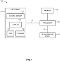
- System 100 includes a user device 110 that includes an imaging sensor 112, a display 114, a global positioning system (GPS) 116, and a compass 118.
- System 100 further includes a processor 120, a memory 122, and a three-dimensional (3D) geographic model 124.
- Processor is communicatively coupled with user device 110, with memory 122, and with 3D model 124.
- User device 110 may be situated at a separate location from processor 120.
- processor 120 may be part of a server, such as a remote computer or remote computer system or machine, which is accessible over a communications medium or network.
- processor 120 may be integrated within user device 110. If user device 110 and processor 120 are remotely located (as shown in Fig.1 ), then a data communication channel 130 (e.g., a wireless link) enables data communication between processor 120 and the components of user device 110.
- processor 120 may be situated at a separate location from 3D model 124, in which case a data communication channel 132 (e.g., a wireless link) enables data transmission between 3D model 124 and processor 120.
- a data communication channel 130 e.g., a wireless link
- User device 110 may be any type of computational device or machine containing at least an imaging sensor 112 and position and orientation determining components (such as GPS 116 and compass 118).
- user device 110 may be embodied by: a smartphone, a mobile phone, a camera, a laptop computer, a netbook computer, a tablet computer, a handheld computer, a personal digital assistant (PDA), a portable media player, a gaming console, or any combination of the above.
- display 114 may be integrated within user device 110 (as shown in Fig.1 ) or otherwise associated therewith, or alternatively display 114 may be part of a separate device that is accessible to and viewable by a user.
- display 114 may be embodied by: the display screen of a computational device (e.g., a smartphone display screen, a tablet computer display screen, a camera display screen and the like); a wearable display device (e.g., goggles, eyeglasses, contact lenses, a head-mounted display (HMD), and the like); a monitor; a head-up display (HUD); a camera viewfinder; and the like.
- a computational device e.g., a smartphone display screen, a tablet computer display screen, a camera display screen and the like
- a wearable display device e.g., goggles, eyeglasses, contact lenses, a head-mounted display (HMD), and the like
- a monitor e.g., a head-up display (HUD), a camera viewfinder; and the like.
- HUD head-up display
- Camera viewfinder e.g., a camera viewfinder
- Imaging sensor 112 may be any type of device capable of acquiring and storing an image representation of a real-world scene, including the acquisition of any form of electromagnetic radiation at any range of wavelengths (e.g., light in the visible or non-visible spectrum, ultraviolet, infrared, radar, microwave, RF, and the like). Imaging sensor 112 is operative to acquire at least one image frame, such as a sequence of consecutive image frames representing a video image, which may be converted into an electronic signal for subsequent processing and/or transmission. Accordingly, the term "image” as used herein refers to any form of output from an aforementioned image sensor, including any optical or digital representation of a scene acquired at any spectral region.
- image refers to any form of output from an aforementioned image sensor, including any optical or digital representation of a scene acquired at any spectral region.
- GPS 116 and compass 118 represent exemplary instruments configured to measure, respectively, the position and orientation of user device 110.
- User device 110 may alternatively include other position and/or orientation measurement instruments, which may be embodied by one or more devices or units, including but not limited to: an inertial navigation system (INS); an inertial measurement unit (IMU); motion sensors or rotational sensors (e.g., accelerometers, gyroscopes, magnetometers); a rangefinder; and the like.
- INS inertial navigation system
- IMU inertial measurement unit
- motion sensors or rotational sensors e.g., accelerometers, gyroscopes, magnetometers
- a rangefinder e.g., a rangefinder
- Data communication channels 130, 132 may be embodied by any suitable physical or logical transmission medium operative for conveying an information signal between two points, via any type of channel model (digital or analog) and using any transmission protocol or network (e.g., radio, HF, wireless, Bluetooth, cellular, and the like).
- User device 110 may further include a transceiver (not shown) operative for transmitting and/or receiving data through communication channel 130.
- 3D geographic model 124 may be any type of three-dimensional representation of the Earth or of a particular area, region or territory of interest. Such a 3D model may include what is known in the art as a: “virtual globe”, “digital elevation model (DEM)”, “digital terrain model (DTM)”, “digital surface model (DSM)”, and the like. 3D model 124 generally includes imagery and texture data relating to geographical features and terrain, including artificial features (e.g., buildings, monuments, and the like), such as the location coordinates of such features and different views thereof (e.g., acquired via satellite imagery or aerial photography, and/or street level views).
- artificial features e.g., buildings, monuments, and the like
- the location coordinates of such features and different views thereof e.g., acquired via satellite imagery or aerial photography, and/or street level views.
- 3D model 124 can provide a plurality of visual representations of the geographical terrain of a region of interest at different positions and viewing angles (e.g., by allowing manipulation operations such as zooming, rotating, tilting, etc).
- 3D model 124 may include a proprietary and/or publically accessible model (e.g., via open-source platforms), or may include a model that is at least partially private or restricted.
- Some examples of publically available 3D models include: Google EarthTM; Google Street ViewTM; NASA World WindTM; Bing MapsTM; Apple Maps; and the like.
- the components and devices of system 100 may be based in hardware, software, or combinations thereof. It is appreciated that the functionality associated with each of the devices or components of system 100 may be distributed among multiple devices or components, which may reside at a single location or at multiple locations. For example, the functionality associated with processor 120 may be distributed between multiple processing units (such as a dedicated image processor for the image processing functions). System 100 may optionally include and/or be associated with additional components (not shown) for performing the functions of the disclosed subject matter, such as: a user interface, external memory, storage media, microprocessors, databases, and the like.
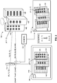
- FIG. 2 is a schematic illustration of an exemplary scene and the resultant images obtained with the system of Figure 1 , operative in accordance with an embodiment of the present invention.
- a real-world scene 140 of an area of interest is imaged by imaging sensor 112 of user device 110, resulting in image 160.
- Scene 140 includes a plurality of buildings, referenced 142, 144 and 146, respectively, which appear on sensor image 160.
- imaging sensor 112 While acquiring image 160, imaging sensor 112 is situated at a particular position and at a particular orientation or viewing angle relative to a reference coordinate frame, indicated by respective position coordinates (X 0 , Y 0 , Z 0 ) and viewing angle coordinates ( ⁇ 0 , ⁇ 0 , ⁇ 0 ) of imaging sensor 112 in three-dimensional space (six degrees of freedom).
- the position coordinates and viewing angle coordinates of imaging sensor 112 are determined by GPS 116 and compass 118 of user device 110.
- Imaging sensor 112 is further characterized by additional parameters that may influence the characteristics of the acquired image 160, such as for example: field of view; focal length; optical resolution; dynamic range; sensitivity; signal-to-noise ratio (SNR); lens aberrations; and the like.
- imaging parameters encompasses any parameter or characteristic associated with an imaging sensor that may influence the characteristics of a particular image obtained by that imaging sensor.
- sensor-image 160 depicts buildings 142, 144, 146 from a certain perspective, which is at least a function of the position and the orientation (and other relevant imaging parameters) of imaging sensor 112 during the acquisition of image 160.
- Sensor-image 160 may be converted to a digital signal representation of the captured scene 140, such as in terms of pixel values, which is then forwarded to processor 120.
- the image representation may also be provided to display 114 for displaying the sensor-image 160.
- Scene 140 includes at least one target element 143, which is represented for exemplary purposes by a window of building 142.
- Target element 143 is geolocated at position coordinates ( X , Y, Z ) .
- imaging sensor 112 is geolocated at position and orientation coordinates ( X 0 , Y 0 , Z 0 ; ⁇ 0 , ⁇ 0 , ⁇ 0 ), relative to the same reference coordinate frame.
- the geolocation coordinates of imaging sensor 112 as detected by GPS 116 and compass 118 may have certain deviations with respect to the true or actual geolocation coordinates of imaging sensor 112.
- the detected geolocation of imaging sensor 112 is at deviated position and orientation coordinates ( X 0 + ⁇ X, Y 0 + ⁇ Y, Z 0 + ⁇ Z ; a 0 + ⁇ , ⁇ 0 + ⁇ , ⁇ 0 + ⁇ ) .
- augmented reality content associated with target element 143 were to be superimposed onto sensor-image 160 based on the geolocation of target element 143 relative to the detected geolocation of imaging sensor 112, the AR content may appear on image 160 at a different location than that of target element 143, and may thus be confused or mistaken by a viewer as being associated with a different element (e.g., another object or region of scene 140).
- FIG. 3A is a schematic illustration of exemplary supplementary content being inaccurately superimposed onto a sensor-image, operative in accordance with an embodiment of the present invention.
- Sensor-image 160 depicts buildings 142, 144, 146 at a certain perspective.
- a reticle 150 is to be superimposed onto window 143 of building 142, in order to present to the viewer of display 114 relevant information about that window 143 (for example, to indicate to the viewer that this window 143 represents the window of an office that he/she is intending to visit).
- User device 110 assumes the geolocation of imaging sensor 112 to be at deviated coordinates ( X 0 + ⁇ X, Y 0 + ⁇ Y, Z 0 + ⁇ Z ; a 0 + ⁇ , ⁇ 0 + ⁇ , ⁇ 0 + ⁇ ), and therefore assumes window 143 to be located on sensor-image 160 at image plane coordinates ( x + ⁇ x, y + ⁇ y, z + ⁇ z ), as determined based on the geolocation of window 143 (X, Y, Z) relative to the (deviated) geolocation of imaging sensor 112, using a suitable camera model.
- the reticle 150 is superimposed on sensor-image 160 at image plane coordinates ( x + ⁇ x , y + ⁇ y, z + ⁇ z ) .
- image plane coordinates x + ⁇ x , y + ⁇ y, z + ⁇ z
- reticle 150 appears slightly away from window 143 on sensor-image 160. Consequently, the viewer may inadvertently think that reticle 150 is indicating a different window, such as window 141 or window 145, rather than window 143.
- processor 120 obtains a copy of sensor-image 160 along with the detected position coordinates ( X 0 , + ⁇ X Y 0 + ⁇ Y, Z 0 + ⁇ Z ) and viewing angle coordinates ( ⁇ + ⁇ , ⁇ 0 + ⁇ , ⁇ 0 + ⁇ ) of imaging sensor 112 (and any other relevant imaging parameters) from user device 110.
- Processor 120 then proceeds to generate a corresponding image 170 of scene 140 based on 3D model 124.
- processor 120 generates a virtual image of the real-world representation of scene 140 contained within 3D model 124 (e.g., using 3D rendering techniques), where the virtual image is what would be acquired by a hypothetical imaging sensor using the imaging parameters associated with sensor-image 160 as obtained from user device 110.
- the resultant model-image 170 should appear quite similar, and perhaps nearly identical, to sensor-image 160 since similar imaging parameters are applied to both images 160, 170.
- the portions of buildings 142, 144, 146 that were visible on sensor-image 160 are also visible on model-image 170, and appear at a similar perspective.
- model-image 170 is based on a (hypothetical) imaging sensor geolocated at (deviated) coordinates ( X 0 + ⁇ X, Y 0 + ⁇ Y, Z 0 + ⁇ Z ; a 0 + ⁇ , ⁇ 0 + ⁇ , ⁇ 0 + ⁇ ) when imaging scene 140, since those are the imaging parameters that were detected by user device 110, whereas sensor-image 160 is based on (actual) imaging sensor 112 that was geolocated at (true) coordinates ( X 0 , Y 0 , Z 0 ; ⁇ 0 , ⁇ 0 , ⁇ 0 ) when imaging scene 140.
- mapping of window 143 on model-image 170 is at image plane coordinates ( x', y', z' ) that are slightly different from the image plane coordinates ( x, y, z ) of window 143 on sensor-image 160.
- processor 120 compares the sensor-image 160 with the model-image 170, and determines the discrepancies between the two images in three-dimensional space or six degrees of freedom (6DoF) (i.e., encompassing translation and rotation in three perpendicular spatial axes).
- processor 120 may use image registration techniques known in the art (e.g., intensity-based or feature-based registration), to determine the corresponding locations of common points or features in the two images 160, 170.
- Processor 120 may determine a suitable 3D transform (mapping) that would map model-image 170 onto sensor-image 160 (or vice-versa), which may include linear transforms (i.e., involving rotation, scaling, translation, and other affine transforms) and/or non-linear transforms.
- a suitable 3D transform mapping
- linear transforms i.e., involving rotation, scaling, translation, and other affine transforms
- processor 120 can then determine the true geolocation of imaging sensor 112 based on the discrepancies between the two images 160, 170. Consequently, deviations in the image contents displayed in sensor-image 160 arising from the inaccuracy of the detected geolocation of imaging sensor 112 can be corrected, allowing geographically-registered AR content to be accurately displayed on sensor-image 160.
- processor 120 determines an updated position and orientation of imaging sensor 112, which would result in model-image 170 being mapped onto sensor-image 160 (i.e., such that the image location of a selected number of points or features in model-image 170 would substantially match the image location of those corresponding points or features as they appear in sensor-image 160, or vice-versa).
- the updated geolocation (position and orientation) of imaging sensor 112 corresponds to the geolocation of a (hypothetical) imaging sensor that would have acquired an updated model-image resulting from the mapping of model-image 170 onto sensor-image 160.
- the determined updated geolocation of imaging sensor 112 should correspond to its actual or true geolocation when acquiring sensor-image 160 (i.e., position coordinates X 0 , Y 0 , Z 0 ; and orientation coordinates ⁇ 0 , ⁇ 0 , ⁇ 0 ) .
- Supplementary AR content can then be accurately displayed on sensor-image 160 in relation to a selected image location or in relation to the real-world geolocation of an object or feature in scene 140 that appears on sensor-image 160, in accordance with the updated geolocation of imaging sensor 112.
- user device 110 identifies at least one scene element viewable on sensor-image 160, in relation to which supplementary AR content is to be displayed.
- User device 110 determines the real-world geolocation of the scene element, and then determines the corresponding image location of the scene element on sensor-image 160, based on the geolocation of the scene element with respect to the updated geolocation of imaging sensor 112 (as determined by processor 112 from the discrepancies between model-image 170 and sensor-image 160).
- Display 114 then displays the supplementary AR content on sensor-image 160 at the appropriate image location relative to the determined image location of the scene element on sensor-image 160.
- an "inaccurate" image location of the scene element as initially determined based on the (inaccurate) detected geolocation of imaging sensor 112 may be corrected to the "true" image location of the scene element as it actually appears on sensor-image 160, such that geographically-registered AR content can be accurately displayed on sensor-image 160 in conformity with the location of the scene element on the sensor-image.
- scene element may refer to any point, object, entity, or feature (or a group of such points, objects, entities or features) that are present in the sensor-image acquired by the imaging sensor of the present invention.
- image location of a scene element may refer to any defined location point associated with such a scene element, such as an approximate center of an entity or feature that appears in the sensor-image.
- Figure 3B is a schematic illustration of the exemplary supplementary content of Figure 3A being accurately superimposed onto the sensor-image, operative in accordance with an embodiment of the present invention.
- a reticle 150 is to be superimposed onto window 143 of building 142, in order to present relevant information about window 143 to the viewer of display 114.
- User device 110 initially assumes the geolocation of imaging sensor 112 to be at (deviated) geolocation coordinates ( X 0 + ⁇ X, Y 0 + ⁇ Y, Z 0 + ⁇ Z ; a 0 + ⁇ , ⁇ 0 + ⁇ , ⁇ 0 + ⁇ ), based on which reticle 150 would be superimposed at deviated image plane coordinates ( x + ⁇ x, y + ⁇ y, z + ⁇ z ) on sensor-image 160 ( Fig. 3A ).
- Processor 120 determines updated geolocation coordinates of imaging sensor 112 ( X 0 , Y 0 , Z 0 ; ⁇ 0 , ⁇ 0 , ⁇ 0 ) , in accordance with the discrepancies between sensor-image 160 and model-image 170.
- User device 110 determines updated image plane coordinates of window 143 on sensor-image 160 (x, y, z), based on the real-world geolocation coordinates of window 143 (X, Y, Z) relative to the updated real-world geolocation coordinates of imaging sensor 112 ( X 0 , Y 0 , Z 0 ; ⁇ 0 , ⁇ 0 , A 0 ) .
- Reticle 150 is then superimposed on sensor-image 160 at the updated image plane coordinates ( x, y, z ), such that it appears at the same location as window 143 on sensor-image 160 (i.e., at the true image location of window 143). Consequently, the viewer of display 114 sees reticle 150 positioned directly onto window 143 of building 142, so that it is clear that the reticle 150 is indicating that particular window 143, rather than a different window in the vicinity of window 143 (such as windows 141, 145).
- the supplementary AR content projected onto display 114 may be any type of graphical or visual design, including but not limited to: text; images; illustrations; symbology; geometric designs; highlighting; changing or adding the color, shape, or size of the image feature (environmental element) in question; and the like.
- supplementary AR content may include audio information, which may be presented in addition to, or instead of, visual information, such as the presentation of video imagery or relevant speech announcing or elaborating upon features of interest that are viewable in the displayed image.
- the operator of user device 110 viewing image 160 on display 114 may designate at least one object of interest on image 160, and then processor 120 may display appropriate AR content related to the designated object(s) of interest.
- the operator may select building 146 on image 160, such as via a speech command or by marking building 146 with a cursor or touch-screen interface on display 114.
- processor 120 identifies the designated object as representing building 146, determines relevant information regarding the designated object, and then projects relevant supplementary content in relation to that designated object (such as the address, a list of occupants or shops residing in that building, and the like) superimposed onto image 160 viewed on display 114, in conformity with the location of building 146 as it appears on image 160.
- Processor 120 may also use the updated geolocation of imaging sensor 112 to extract correct real-world geolocation information relating to scene 140, without necessarily projecting supplementary AR content on sensor-image 160. For example, processor 120 may determine the real-world geolocation coordinates of an object or feature in scene 140, such as the real-world geolocation of window 143, from 3D model 124, based on the determined updated geolocation of imaging sensor 112.
- processor 120 identifies the updated geolocation coordinates of imaging sensor 112 ( X 0 , Y 0 , Z 0 ; ⁇ 0 , ⁇ 0 , ⁇ 0 ) in 3D model 124, and projects a vector extending from the imaging sensor coordinates to the object of interest coordinates within the 3D model, the projection vector having a length corresponding to the range from the imaging sensor geolocation to the object of interest geolocation (where the range is determined using any suitable means, such as a rangefinder).
- processor 120 determines the coordinates of a vector in 3D model 124 extending from the updated geolocation coordinates of imaging sensor 112 ( X 0 , Y 0 , Z 0 ; ⁇ 0 , ⁇ 0 , ⁇ 0 ) and having a length equal to the range from imaging sensor 112 to window 143, such that the end position of the vector indicates the geolocation coordinates of window 143 ( X, Y, Z ).
- geographically-registered supplementary content may be projected onto a sequence of displayed images with imaging parameters that change over time, where the position and orientation of the image contents is tracked and the relevant AR content is updated accordingly.
- imaging sensor 112 may acquire a second image (not shown) of scene 140, at a different position and viewing angle (e.g., X 1 , Y 1 , Z 1 ; ⁇ 1 , ⁇ 1 , ⁇ 1 ) than that associated with the previous image 160.
- user device 110 would detect an inaccurate geolocation of imaging sensor 112 during the acquisition of the second sensor-image (e.g., at deviated coordinates X 1 + ⁇ X 1 , Y 1 + ⁇ Y 1 , Z 1 + ⁇ Z 1 ; ⁇ 1 + ⁇ 1 , ⁇ 1 + ⁇ ⁇ 1 , ⁇ 1 + ⁇ ⁇ 1 ), and would therefore map window 143 on the second sensor-image at a second set of deviated image coordinates (e.g., x + ⁇ x 1 , y + ⁇ y 1 , z + ⁇ z 1 ) which differs from the window coordinates in the first sensor-image ( x, y, z ) .
- a second set of deviated image coordinates e.g., x + ⁇ x 1 , y + ⁇ y 1 , z + ⁇ z 1
- processor 120 In order to present correctly georegistered AR content associated with window 143 on the second sensor-image, one approach is to repeat the aforementioned process described for a single image.
- processor 120 generates a second model-image from 3D model 124, the second model-image representing a virtual image as acquired in 3D model 114 with a hypothetical imaging sensor using the detected imaging parameters associated with the second model-image.
- Processor 120 compares and determines discrepancies between the second model-image and the second sensor-image, and determines the image plane coordinates of window 143 on the second sensor-image based on the geolocation of window 143 with respect to an updated geolocation of imaging sensor 112 as determined from the discrepancies between the second model-image and the second sensor-image.
- the relevant supplementary AR content (e.g., reticle 150) is then displayed at the determined image plane coordinates on the second sensor-image, such that reticle 150 will be displayed at the same image location as window 143 as it actually appears on the second sensor-image.
- a second approach is to utilize standard image tracking techniques to track the location of the scene element between image frames in order to determine the correct placement for superposition of the AR content in subsequent frames, and then intermittently apply the aforementioned process (i.e., determining an updated model-image, comparing with the associated sensor-image, and determining an updated geolocation of imaging sensor 112 accordingly) after a selected number of frames in order to "recalibrate".
- An additional approach would be to incorporate predicted values of the imaging sensor geolocation (i.e., predicting the future location of the operator of user device 110), in accordance with a suitable prediction model.
- geographically-registered supplementary content may be projected onto multiple displayed images of the same (or a similar) scene, acquired by a plurality of imaging sensors, each being associated with respective imaging parameters.
- a plurality of imaging sensors (112A, 112B, 112C) may acquire a plurality of respective sensor-images (160A, 160B, 160C) of scene 140, each sensor-image being associated with at least a respective position and viewing angle (and other relevant imaging parameters).
- window 143 of building 142 may appear at a slightly different image location at each of the respective sensor-images 160A, 160B, 160C.
- Processor 120 generates a set of model-images from 3D model 124, each model-image (170A, 170B, 170C) respective of each of the sensor-images (160A, 160B, 160C) based on the associated detected imaging parameters. Subsequently, processor 120 compares between each sensor-image and its respective model-image (170A, 170B, 170C), and determines the discrepancies and deviations between each pair of images.
- Processor 120 determines the true geolocation of each imaging sensor (112A, 112B, 112C) for its respective sensor-image (160A, 160B, 160C), based on the discrepancies between each sensor-image (160A, 160B, 160C) and its respective model-image (170A, 170B, 170C).
- a selected image location (e.g., associated with a scene element) is then determined for each sensor-image (160A, 160B, 160C) based on the determined real-world geolocation of the respective imaging sensor (112A, 112B, 112C), and the respective supplementary AR content is superimposed at the correct geographically-registered image coordinates on each of the sensor-images (160A, 160B, 160C) presented on a plurality of displays (114A, 114B, 11C).
- An example of such a scenario may be a commander of a military sniper unit who is directing multiple snipers on a battlefield, where the commander and each of the snipers are viewing the potential target at different positions and viewing angles through the sighting device of their respective weapons.
- the commander may then indicate to each of the snipers the exact position of the desired target with respect to the particular image being viewed by that sniper, in accordance with the present invention.
- images of the potential target acquired by the cameras of each sniper are processed, and a model-image respective of each sniper's image is generated using the 3D geographic model, based on the detected imaging parameters associated with the respective sniper image.
- the discrepancies between each model-image and the respective sniper image are determined, and the geolocation of each sniper camera for its respective sniper image is determined based on these discrepancies.
- an appropriate symbol (such as a reticle) can be superimposed onto the sighting device being viewed by each respective sniper, at the image location of the desired target as it appears on the respective sniper's image.
- 3D geographic model 124 may be updated based on real-time information, such as information obtained in the acquired sensor-image 160, following the image georegistration process.
- real-time information such as information obtained in the acquired sensor-image 160
- the texture data contained within 3D model 124 may be amended to conform with real-world changes in the relevant geographical features or terrain.
- processor may identify a discrepancy between a particular characteristic of a geographical feature as it appears in recently acquired sensor-image 160 and the corresponding characteristic of the geographical feature as currently defined in 3D model 124, and then proceed to update 3D model 124 accordingly.
- 3D geographic model 124 may be stored in a remote server or database, and may be accessed by processor 120 partially or entirely, as required. For example, processor 120 may retrieve only the relevant portions of 3D model 124 (e.g., only the portions relating to the particular region or environment where scene 140 is located), and store the data in a local cache memory for quicker access. Processor 120 may also utilize the current geolocation of user device 110 (i.e., as detected using GPS 116) in order to identify a suitable 3D geographic model 124, or section thereof, to retrieve. In other words, a location-based 3D model 124 may be selected in accordance with the real-time geolocation of user device 110.
- information relating to georegistered images over a period of time may be stored, and then subsequent image georegistration may be implemented using the previously georegistered images, rather than using 3D model 124 directly.
- a database (not shown) may store the collection of sensor-images captured by numerous users of system 100, along with relevant image information and the associated true position and orientation coordinates as determined in accordance with the discrepancies between the sensor-image and corresponding model-image generated from 3D model 124. After a sufficient amount of georegistered sensor-images have been collected, then subsequent iterations of georegistration may bypass 3D model 124 entirely.
- system 100 may identify that a new sensor-image was captured at a similar location to a previously georegistered sensor-image (e.g., by identifying a minimum of common environmental features or image attributes in both images). System 100 may then determine an updated position and orientation for the new sensor-image directly from the (previously determined) position and orientation of the previously georegistered sensor-image at the common location (based on the discrepancies between the two images), rather than from a model-image generated for the new sensor-image.
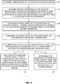
- FIG. 4 is a block diagram of a method for image georegistration, operative in accordance with an embodiment of the present invention.
- procedure 202 a sensor-image of a scene is acquired with an imaging sensor.
- imaging sensor 112 acquires an image 160 of scene 140 that includes a plurality of buildings 142, 144, 146.
- imaging parameters of the acquired sensor-image are obtained, the imaging parameters including at least the detected 3D position and orientation of the imaging sensor when acquiring the sensor-image, as detected using as least one location measurement unit.
- processor 120 receives imaging parameters associated with the acquired sensor-image 160 from user device 110.
- the imaging parameters includes at least the real-world geolocation (position and orientation) of imaging sensor 112 while acquiring sensor-image 160, as detected via GPS 116 and compass 118 of user device 110.
- the detected geolocation of imaging sensor 112 includes position coordinates ( X 0 + ⁇ X, Y 0 + ⁇ Y, Z 0 + ⁇ Z ) and viewing angle coordinates ( ⁇ o + ⁇ , ⁇ 0 + ⁇ , ⁇ 0 + ⁇ ), which are deviated with respect to the true or actual position coordinates ( X 0 , Y 0 , Z 0 ) and orientation coordinates ( ⁇ 0 , ⁇ 0 , ⁇ 0 ) of imaging sensor 112 in three-dimensional space (six degrees of freedom).
- a model-image of the scene is generated from a 3D geographic model, the model-image representing a 2D image of the scene as acquired in the 3D model using the obtained imaging parameters.
- processor 120 generates a model-image 170 of scene 140 based on the 3D geographic data contained in 3D model 124.
- the model-image 170 is a virtual image that would be acquired by a hypothetical imaging sensor imaging scene 140 using the imaging parameters obtained from user device 110, where the imaging parameters includes the detected geolocation of imaging sensor 112 while acquiring sensor-image 160, as detected via GPS 116 and compass 118.
- model-image 170 is based on a hypothetical imaging sensor geolocated at deviated coordinates ( X 0 + ⁇ X, Y 0 + ⁇ Y, Z 0 + ⁇ Z ; a 0 + ⁇ , ⁇ 0 + ⁇ , ⁇ 0 + ⁇ ) when imaging scene 140.
- Model-image 170 should depict mostly the same environmental features (i.e., buildings 142, 144, 146) depicted in sensor-image 160, but they may be located at slightly different image plane coordinates in the two images.
- processor 120 compares sensor-image 160 with model-image 170, and determines the deviations or discrepancies between the two images 160, 170 in three-dimensional space (six degrees of freedom).
- processor 120 may use image registration techniques known in the art to determine the corresponding locations of common points or features in the two images 160, 170, and may determine a transform or mapping between the two images 160, 170.
- an updated 3D position and orientation of the imaging sensor is determined in accordance with the discrepancies between the sensor-image and the model-image.
- processor 120 determines an updated geolocation of imaging sensor 112 based on the discrepancies between sensor-image 160 and model-image 170.
- processor 120 determines an updated position and orientation of imaging sensor 112, such that the image location of a selected number of points or features in model-image 170 would substantially match the image location of those corresponding points or features as they appear in sensor-image 160 (or vice-versa).
- the determined updated geolocation of imaging sensor 112 ( X 0 , Y 0 , Z 0 ; ⁇ 0 , ⁇ 0 , ⁇ 0 ) should correspond to its actual or true geolocation when acquiring sensor-image 160.
- supplementary content is displayed overlaid on the sensor-image in relation to a selected location on the sensor-image, as determined based on the updated position and orientation of the imaging sensor.
- user device 110 determines the image plane coordinates of window 143 on sensor-image 160 (x, y, z ), based on the real-world geolocation coordinates of window 143 ( X, Y, Z ) relative to the updated real-world geolocation coordinates of imaging sensor 112 ( X 0 , Y 0 , Z 0 ; ⁇ 0 , ⁇ 0 , ⁇ 0 ) .
- a reticle 150 is superimposed onto sensor-image 160 at the determined image coordinates of window 143 ( x, y, z ), such that the viewer of display 114 sees reticle 150 positioned directly over window 143 on sensor-image 160.
- the geographic location of a scene element is determined, using the 3D geographic model and the updated position and orientation of the imaging sensor.
- processor 120 determines the real-world geolocation coordinates of window 143 ( X, Y, Z ), as indicated by the coordinates of a vector in 3D model 124 extending from the updated geolocation coordinates of imaging sensor 112 ( X 0 , Y 0 , Z 0 ; ⁇ 0 , ⁇ 0 , ⁇ 0 ) and having a length equal to the range from imaging sensor 112 to window 143.
- the determined geolocation coordinates ( X , Y, Z ) may then be indicated to the viewer if desired, such as being indicated on sensor-image 160 as viewed on display 114.
- the present invention is applicable to augmented reality presentation for any purpose, and may be employed in a wide variety of applications, for projecting any type of graphical imagery or AR content onto a real-world environment in order to modify the viewer's perception of that environment.
- the present invention may be utilized for various military objectives, such as for guiding troops, directing weaponry, and providing target information or indications of potential dangers.
- security related applications such as for analyzing surveillance imagery, directing surveillance cameras towards a particular target, or assisting the deployment of security personnel at a crime scene.
- Yet another potential application is for navigation, such as providing directions to a specific location at a particular street or building.
- Further exemplary applications include education (e.g., such as augmenting an illustration of a particular topic or concept to enhance student comprehension); entertainment (e.g., such as by augmenting a broadcast of a sporting event or theatre performance); and tourism (e.g., such as by providing relevant information associated with a particular location or recreating simulations of historical events).
- education e.g., such as augmenting an illustration of a particular topic or concept to enhance student comprehension
- entertainment e.g., such as by augmenting a broadcast of a sporting event or theatre performance
- tourism e.g., such as by providing relevant information associated with a particular location or recreating simulations of historical events.
Landscapes
- Engineering & Computer Science (AREA)
- Physics & Mathematics (AREA)
- Theoretical Computer Science (AREA)
- General Physics & Mathematics (AREA)
- Computer Vision & Pattern Recognition (AREA)
- Software Systems (AREA)
- Geometry (AREA)
- Computer Graphics (AREA)
- General Engineering & Computer Science (AREA)
- Data Mining & Analysis (AREA)
- Remote Sensing (AREA)
- Computer Hardware Design (AREA)
- Life Sciences & Earth Sciences (AREA)
- Bioinformatics & Computational Biology (AREA)
- Evolutionary Biology (AREA)
- Evolutionary Computation (AREA)
- Bioinformatics & Cheminformatics (AREA)
- Artificial Intelligence (AREA)
- Processing Or Creating Images (AREA)
- Studio Devices (AREA)
- User Interface Of Digital Computer (AREA)
- Controls And Circuits For Display Device (AREA)
Claims (14)
- Système de recalage géographique d'images, le procédé comprenant les procédures :d'acquisition (202) d'une unique image de capteur (160) d'une scène avec un capteur d'imagerie (112) d'un dispositif utilisateur (110), l'image de capteur (160) comprenant du contenu d'image textural détaillé ;d'obtention (204) de paramètres d'imagerie de l'image de capteur acquise (160), par un processeur (120) dudit dispositif utilisateur (110), lesdits paramètres d'imagerie comprenant au moins la position et l'orientation tridimensionnelles (3D) détectées dudit capteur d'imagerie (112) lors de l'acquisition de ladite image de capteur (160), telles que détectées en utilisant au moins une unité de mesure d'emplacement (116, 118) dudit dispositif utilisateur (110) ;de génération (206), en utilisant les paramètres d'imagerie de l'image de capteur acquise (160), par ledit processeur (120), d'une image de modèle (170) de ladite scène à partir d'un modèle géographique 3D texturé (124) couplé en communication audit dispositif utilisateur (110), ledit modèle 3D (124) fournissant différentes vues de caractéristiques géographiques et de terrain incluant des vues aériennes et des vues au niveau des rues, ladite image de modèle (170) représentant une image bidimensionnelle (2D) de ladite scène telle qu'elle serait acquise dans ledit modèle géographique 3D (124) par un capteur d'image hypothétique utilisant lesdits paramètres d'imagerie comprenant l'emplacement géographique détecté du capteur d'imagerie (112) lors de l'acquisition de l'image de capteur (160), l'emplacement géographique détecté du capteur d'imagerie (112) correspondant à n'importe quelles position et orientation dans le modèle 3D (124) de sorte que l'image de modèle générée (170) représente n'importe quel point de vue des caractéristiques géographiques et du terrain, incluant une vue au niveau des rues, ladite image de modèle (170) comprenant du contenu d'image textural détaillé en plus de caractéristiques de contour ;de comparaison (208), par ledit processeur (120), du contenu d'image texturé détaillé de ladite image de capteur (160) avec le contenu d'image texturé détaillé de ladite image de modèle (170) et la détermination d'écarts entre elles ;de détermination (210), par ledit processeur (120), d'une position et d'une orientation 3D mises à jour dudit capteur d'imagerie (112) en fonction des écarts entre ladite image de capteur (160) et ladite image de modèle (170) ; etd'affichage (212) de contenu supplémentaire superposé à ladite image de capteur (160), avec un dispositif d'affichage (114) dudit dispositif utilisateur (110), en rapport avec un emplacement sélectionné sur ladite image de capteur (160), tel que déterminé sur la base desdites position et orientation 3D mises à jour dudit capteur d'imagerie (112).
- Procédé selon la revendication 1, comprenant en outre la procédure de détermination (214) des coordonnées d'emplacement géographique d'un élément de scène, en utilisant ledit modèle géographique 3D (124) et lesdites position et orientation 3D mises à jour dudit capteur d'imagerie (112).
- Procédé selon la revendication 1, dans lequel lesdits paramètres d'imagerie comprennent en outre au moins paramètre sélectionné dans la liste composée :de la distance dudit capteur d'imagerie (112) à ladite scène ;du champ de vision dudit capteur d'imagerie (112) ;de la longueur focale dudit capteur d'imagerie (112) ;de la résolution optique dudit capteur d'imagerie (112) ;de la gamme dynamique dudit capteur d'imagerie (112) ;de la sensibilité dudit capteur d'imagerie (112) ;du rapport signal sur bruit (RSB) dudit capteur d'imagerie (112) ; etd'aberrations de lentille dudit capteur d'imagerie (112).
- Procédé selon la revendication 1, comprenant en outre la procédure de mise à jour des données de texture dudit modèle géographique 3D (124), en fonction de données de texture obtenues à partir de ladite image de capteur (160).
- Procédé selon la revendication 1, comprenant en outre les procédures :de suivi de l'emplacement d'un élément de scène sur une séquence d'images fixes de ladite image de capteur (160) ; etd'affichage de contenu supplémentaire superposé à au moins une image fixe de ladite séquence d'images fixes, en rapport avec l'emplacement dudit élément de scène dans ladite image fixe, tel que déterminé relativement à une image fixe précédente de ladite séquence d'images fixes.
- Procédé selon la revendication 1, comprenant en outre les procédures :d'obtention d'au moins un second ensemble de paramètres d'imagerie pour au moins une seconde image de capteur (160) de ladite au moins une image de capteur (160) acquise par ledit capteur d'imagerie ;de génération d'au moins une seconde image de modèle (170) de ladite scène à partir dudit modèle géographique 3D (124), ladite seconde image de modèle (170) représentant une image 2D de ladite scène telle qu'acquise dans ledit modèle géographique 2D (124) en utilisant ledit second ensemble de paramètres d'imagerie ;de comparaison de ladite seconde image de capteur (160) et de ladite seconde image de modèle (170) et de détermination des écarts entre elles ;de détermination d'une position et d'une orientation 3D mises à jour dudit capteur d'imagerie (112) en ce qui concerne ladite seconde image de capteur (160), en fonction des écarts entre ladite seconde image de capteur (160) et ladite seconde image de modèle (170) ; etd'affichage de contenu supplémentaire superposé à ladite seconde image de capteur (160), en rapport avec un emplacement sélectionné sur ladite seconde image de capteur (160), tel que déterminé sur la base desdites position et orientation 3D mises à jour dudit capteur d'imagerie (112) en ce qui concerne ladite seconde image de capteur (160).
- Procédé selon la revendication 1, dans lequel ledit contenu supplémentaire est affiché sur au moins un dispositif d'affichage partiellement transparent situé dans le champ de vision d'un utilisateur, permettant une observation simultanée de ladite image de capteur (160) présentée sur ledit dispositif d'affichage et de ladite scène à travers ledit dispositif d'affichage.
- Système (100) de recalage géographique d'images, le système (100) comprenant :un modèle géographique 3D texturé (124), ledit modèle incluant des données d'imagerie et de texture relatives à des caractéristiques géographiques et à un terrain, incluant des caractéristiques artificielles, ledit modèle 3D (124) fournissant différentes vues des caractéristiques géographiques et du terrain incluant des vues aériennes et des vues au niveau des rues ;un dispositif utilisateur (110), couplé en communication audit modèle géographique 3D (124), ledit dispositif utilisateur (110) comprenant :un capteur d'imagerie (112), configuré pour acquérir une unique image de capteur (160) d'une scène (140), l'image de capteur (160) comprenant du contenu d'image textural détaillé ; etau moins une unité de mesure d'emplacement (116, 118), configurée pour détecter la position et l'orientation 3D dudit capteur d'imagerie (112) lors de l'acquisition de ladite image de capteur (160) ;dans lequel le dispositif utilisateur (110) comprend en outre :un processeur (120), configuré pour obtenir des paramètres d'imagerie de l'image de capteur acquise (160), lesdits paramètres d'imagerie comprenant au moins la position et l'orientation 3D détectées dudit capteur d'imagerie (112) lors de l'acquisition de ladite image de capteur (160) telles que détectées en utilisant ladite unité de mesure d'emplacement, ledit processeur (120) étant en outre configuré pour générer une image de modèle (170) de ladite scène à partir dudit modèle géographique 3D (124), en utilisant les paramètres d'imagerie de l'image de capteur acquise (160), ladite image de modèle (170) représentant une image 2D de ladite scène telle qu'elle serait acquise dans ledit modèle géographique 3D (124) par un capteur d'image hypothétique utilisant lesdits paramètres d'imagerie comprenant l'emplacement géographique détecté du capteur d'imagerie (112) lors de l'acquisition de l'image de capteur (160), l'emplacement géographique détecté du capteur d'imagerie (112) correspondant à n'importe quelles position et orientation dans le modèle 3D (124) de sorte que l'image de modèle générée (170) représente n'importe quel point de vue des caractéristiques géographiques et du terrain, incluant une vue au niveau des rues, ladite image de modèle (170) comprenant du contenu d'image textural détaillé en plus de caractéristiques de contour, ledit processeur (120) étant en outre configuré pour comparer le contenu d'image textural détaillé de ladite image de capteur (160) avec le contenu d'image textural détaillé de ladite image de modèle (170) et déterminer des écarts entre elles, et pour déterminer une position et une orientation 3D mises à jour dudit capteur d'imagerie (112) en fonction des écarts entre ladite image de capteur (160) et ladite image de modèle (170) ; etun dispositif d'affichage (114), configuré pour afficher du contenu supplémentaire superposé à ladite image de capteur (160), en rapport avec un emplacement sélectionné sur ladite image de capteur (160), tel que déterminé sur la base desdites position et orientation 3D mises à jour dudit capteur d'imagerie (112).
- Système (100) selon la revendication 8, dans lequel ledit processeur (120) est configuré pour déterminer les coordonnées d'emplacement géographique d'un élément de scène, en utilisant ledit modèle géographique 3D (124) et lesdites position et orientation 3D mises à jour dudit capteur d'imagerie (112).
- Système (100) selon la revendication 8, dans lequel ledit processeur (120) est configuré pour mettre à jour les données de texture dudit modèle géographique 3D (124), en fonction de données de texture obtenues à partir de ladite image de capteur (160).
- Système (100) selon la revendication 8, dans lequel ledit dispositif d'affichage comprend au moins un dispositif d'affichage partiellement transparent situé dans le champ de vision d'un utilisateur, permettant une observation simultanée de ladite image de capteur (160) présentée sur ledit dispositif d'affichage et de ladite scène à travers ledit dispositif d'affichage.
- Module de recalage géographique d'images (120, 114), configuré pour obtenir des paramètres d'imagerie d'une unique image de capteur (160) acquise par un capteur d'imagerie (112), l'image de capteur (160) comprenant du contenu d'image textural détaillé, lesdits paramètres d'imagerie comprenant au moins la position et l'orientation 3D détectées dudit capteur d'imagerie (112) lors de l'acquisition de ladite image de capteur (160) telles que détectées en utilisant au moins une unité de mesure d'emplacement (116, 118) ; ledit module étant en outre configuré pour générer une image de modèle (170) de ladite scène à partir d'un modèle géographique 3D texturé (124), en utilisant les paramètres d'imagerie de l'image de capteur acquise (160), ledit modèle 3D (124) incluant des données d'imagerie et de texture relatives à des caractéristiques géographiques et à un terrain, incluant des caractéristiques artificielles, ledit modèle 3D (124) fournissant différentes vues des caractéristiques géographiques et du terrain incluant des vues aériennes et des vues au niveau des rues, ladite image de modèle (170) représentant une image 2D de ladite scène telle qu'elle serait acquise dans ledit modèle géographique 3D (124) par un capteur d'image hypothétique utilisant lesdits paramètres d'imagerie comprenant l'emplacement géographique détecté du capteur d'imagerie (112) lors de l'acquisition de l'image de capteur (160), l'emplacement géographique détecté du capteur d'imagerie (112) correspondant à n'importe quelles position et orientation dans le modèle 3D (124) de sorte que l'image de modèle générée (170) représente n'importe quel point de vue des caractéristiques géographiques et du terrain, incluant une vue au niveau des rues, ladite image de modèle (170) comprenant du contenu d'image textural détaillé en plus de caractéristiques de contour, ledit module étant en outre configuré pour comparer le contenu d'image textural détaillé de ladite image de capteur (160) avec le contenu d'image textural détaillé de ladite image de modèle (170) et déterminer des écarts entre elles ; et
ledit module étant configuré pour déterminer une position et une orientation 3D mises à jour dudit capteur d'imagerie (112) en fonction des écarts entre ladite image de capteur (160) et ladite image de modèle (170) ; et ledit module étant configuré pour afficher du contenu supplémentaire superposé à ladite image de capteur (160), en rapport avec un emplacement sélectionné sur ladite image de capteur (160), tel que déterminé sur la base desdites position et orientation 3D mises à jour dudit capteur d'imagerie (112). - Module selon la revendication 12, ledit module étant configuré pour déterminer les coordonnées d'emplacement géographique d'un élément de scène, en utilisant ledit modèle géographique 3D (124) et lesdites position et orientation 3D mises à jour dudit capteur d'imagerie (112).
- Module selon la revendication 12, ledit module étant configuré pour mettre à jour les données de texture dudit modèle géographique 3D (124), en fonction de données de texture obtenues à partir de ladite image de capteur (160).
Applications Claiming Priority (2)
| Application Number | Priority Date | Filing Date | Title |
|---|---|---|---|
| IL232853A IL232853A (en) | 2014-05-28 | 2014-05-28 | Method and system for image georegistration |
| PCT/IL2015/050554 WO2015181827A1 (fr) | 2014-05-28 | 2015-05-28 | Procédé et système de géo-alignement d'images |
Publications (3)
| Publication Number | Publication Date |
|---|---|
| EP3149698A1 EP3149698A1 (fr) | 2017-04-05 |
| EP3149698A4 EP3149698A4 (fr) | 2017-11-08 |
| EP3149698B1 true EP3149698B1 (fr) | 2020-12-16 |
Family
ID=54698232
Family Applications (1)
| Application Number | Title | Priority Date | Filing Date |
|---|---|---|---|
| EP15799568.9A Active EP3149698B1 (fr) | 2014-05-28 | 2015-05-28 | Procédé et système de géo-alignement d'images |
Country Status (6)
| Country | Link |
|---|---|
| US (1) | US10204454B2 (fr) |
| EP (1) | EP3149698B1 (fr) |
| AU (1) | AU2015265416B2 (fr) |
| IL (1) | IL232853A (fr) |
| SG (1) | SG11201609859YA (fr) |
| WO (1) | WO2015181827A1 (fr) |
Families Citing this family (59)
| Publication number | Priority date | Publication date | Assignee | Title |
|---|---|---|---|---|
| GB2531531A (en) * | 2014-10-20 | 2016-04-27 | Bae Systems Plc | Optical inertial measurement apparatus and method |
| US9652896B1 (en) | 2015-10-30 | 2017-05-16 | Snap Inc. | Image based tracking in augmented reality systems |
| US9984499B1 (en) | 2015-11-30 | 2018-05-29 | Snap Inc. | Image and point cloud based tracking and in augmented reality systems |
| US10217236B2 (en) | 2016-04-08 | 2019-02-26 | Orbital Insight, Inc. | Remote determination of containers in geographical region |
| EP3440428B1 (fr) | 2016-04-08 | 2022-06-01 | Orbital Insight, Inc. | Détermination à distance d'une quantité stockée dans des conteneurs dans une région géographique |
| JP6917820B2 (ja) * | 2016-08-05 | 2021-08-11 | 株式会社半導体エネルギー研究所 | データ処理システム |
| DE102016120366A1 (de) * | 2016-10-25 | 2018-04-26 | Deutsches Zentrum für Luft- und Raumfahrt e.V. | Mobile Einheit und Verfahren zum Anzeigen georeferenzierter Daten |
| US10802135B2 (en) * | 2016-12-21 | 2020-10-13 | The Boeing Company | Method and apparatus for raw sensor image enhancement through georegistration |
| US11175398B2 (en) * | 2016-12-21 | 2021-11-16 | The Boeing Company | Method and apparatus for multiple raw sensor image enhancement through georegistration |
| US10319149B1 (en) | 2017-02-17 | 2019-06-11 | Snap Inc. | Augmented reality anamorphosis system |
| US10074381B1 (en) | 2017-02-20 | 2018-09-11 | Snap Inc. | Augmented reality speech balloon system |
| EP3385747B1 (fr) * | 2017-04-05 | 2021-03-31 | Axis AB | Procédé, dispositif et système de mappage de détections de position à une représentation graphique |
| WO2018184816A1 (fr) | 2017-04-06 | 2018-10-11 | Novozymes A/S | Compositions de nettoyage et leurs utilisations |
| US10387730B1 (en) | 2017-04-20 | 2019-08-20 | Snap Inc. | Augmented reality typography personalization system |
| US10524165B2 (en) | 2017-06-22 | 2019-12-31 | Bank Of America Corporation | Dynamic utilization of alternative resources based on token association |
| US10511692B2 (en) * | 2017-06-22 | 2019-12-17 | Bank Of America Corporation | Data transmission to a networked resource based on contextual information |
| DE102017213555A1 (de) * | 2017-08-04 | 2019-02-07 | Siemens Aktiengesellschaft | Vorrichtung und Verfahren zum winkelbasierten Lokalisieren einer Position auf einer Oberfläche eines Objekts |
| US10535119B2 (en) * | 2017-08-11 | 2020-01-14 | Intermap Technologies Inc. | Method and apparatus for enhancing 3D model resolution |
| US10347008B2 (en) * | 2017-08-14 | 2019-07-09 | Trimble Inc. | Self positioning camera system to 3D CAD/BIM model |
| US10740974B1 (en) | 2017-09-15 | 2020-08-11 | Snap Inc. | Augmented reality system |
| CN111295663B (zh) * | 2017-11-06 | 2024-08-13 | 索尼公司 | 信息处理装置、信息处理方法和程序 |
| IL255671B (en) * | 2017-11-14 | 2021-09-30 | Everysight Ltd | System and method for determining an image position using one or more anchors |
| US11232645B1 (en) | 2017-11-21 | 2022-01-25 | Amazon Technologies, Inc. | Virtual spaces as a platform |
| US10732708B1 (en) * | 2017-11-21 | 2020-08-04 | Amazon Technologies, Inc. | Disambiguation of virtual reality information using multi-modal data including speech |
| ES2890428T3 (es) | 2017-12-19 | 2022-01-19 | Ericsson Telefon Ab L M | Dispositivo de visualización montado en la cabeza y su método |
| US20190377538A1 (en) | 2018-06-08 | 2019-12-12 | Curious Company, LLC | Information Presentation Through Ambient Sounds |
| US10937150B2 (en) * | 2018-06-28 | 2021-03-02 | General Electric Company | Systems and methods of feature correspondence analysis |
| US10964033B2 (en) * | 2018-08-07 | 2021-03-30 | Qualcomm Incorporated | Decoupled motion models for object tracking |
| US11195324B1 (en) * | 2018-08-14 | 2021-12-07 | Certainteed Llc | Systems and methods for visualization of building structures |
| US10997760B2 (en) | 2018-08-31 | 2021-05-04 | Snap Inc. | Augmented reality anthropomorphization system |
| US10902678B2 (en) | 2018-09-06 | 2021-01-26 | Curious Company, LLC | Display of hidden information |
| US11886189B2 (en) | 2018-09-10 | 2024-01-30 | Perceptual Robotics Limited | Control and navigation systems, pose optimization, mapping, and localization techniques |
| GB2577134B (en) | 2018-09-10 | 2021-01-13 | Perceptual Robotics Ltd | Control and navigation systems |
| GB2581403B (en) * | 2019-02-13 | 2022-11-23 | Perceptual Robotics Ltd | Pose optimisation, mapping, and localisation techniques |
| CN109561278B (zh) * | 2018-09-21 | 2020-12-29 | 中建科技有限公司深圳分公司 | 一种增强现实的显示系统及方法 |
| EP3861387B1 (fr) | 2018-10-05 | 2025-05-21 | Magic Leap, Inc. | Rendu d'un contenu virtuel spécifique à un emplacement dans n'importe quel emplacement |
| US10885657B2 (en) | 2018-10-31 | 2021-01-05 | Disney Enterprises, Inc. | Configuration for indicating image capture device position |
| US11055913B2 (en) | 2018-12-04 | 2021-07-06 | Curious Company, LLC | Directional instructions in an hybrid reality system |
| EP4296943B1 (fr) * | 2018-12-26 | 2025-07-02 | Elbit Systems Land and C4I Ltd. | Procédés et systèmes de détermination de la pose d'une caméra 3d |
| US11972529B2 (en) | 2019-02-01 | 2024-04-30 | Snap Inc. | Augmented reality system |
| US11002541B2 (en) | 2019-07-23 | 2021-05-11 | Trimble Inc. | Target positioning with electronic distance measuring and bundle adjustment |
| US10997747B2 (en) | 2019-05-09 | 2021-05-04 | Trimble Inc. | Target positioning with bundle adjustment |
| US11699279B1 (en) | 2019-06-28 | 2023-07-11 | Apple Inc. | Method and device for heading estimation |
| US11532093B2 (en) | 2019-10-10 | 2022-12-20 | Intermap Technologies, Inc. | First floor height estimation from optical images |
| EP4046070A4 (fr) | 2019-10-15 | 2023-10-18 | Magic Leap, Inc. | Système de réalité étendue prenant en charge de multiples types de dispositifs |
| US11315326B2 (en) * | 2019-10-15 | 2022-04-26 | At&T Intellectual Property I, L.P. | Extended reality anchor caching based on viewport prediction |
| US10907977B1 (en) | 2019-10-22 | 2021-02-02 | Cubic Corporation | Human-aided geo-rectification of geospatial metadata in video using a graphical interface |
| CN114762008A (zh) | 2019-12-09 | 2022-07-15 | 奇跃公司 | 简化的虚拟内容编程的交叉现实系统 |
| US11315346B2 (en) * | 2020-01-16 | 2022-04-26 | Square Enix Co., Ltd. | Method for producing augmented reality image |
| JP7768888B2 (ja) | 2020-02-13 | 2025-11-12 | マジック リープ, インコーポレイテッド | マルチ分解能フレーム記述子を使用したマップ処理を伴うクロスリアリティシステム |
| JP7671769B2 (ja) | 2020-02-26 | 2025-05-02 | マジック リープ, インコーポレイテッド | 高速位置特定を伴うクロスリアリティシステム |
| WO2022011277A2 (fr) | 2020-07-10 | 2022-01-13 | Overwatch Systems, Ltd. | Suivi géospatial en temps réel |
| EP4036859A1 (fr) | 2021-01-27 | 2022-08-03 | Maxar International Sweden AB | Système et procédé pour fournir des données de référence géocodées améliorées à une représentation de carte 3d |
| US11551366B2 (en) | 2021-03-05 | 2023-01-10 | Intermap Technologies, Inc. | System and methods for correcting terrain elevations under forest canopy |
| US20230260240A1 (en) * | 2021-03-11 | 2023-08-17 | Quintar, Inc. | Alignment of 3d graphics extending beyond frame in augmented reality system with remote presentation |
| WO2023009112A1 (fr) * | 2021-07-28 | 2023-02-02 | Innopeak Technology, Inc. | Rendu de contenu à réalité augmentée |
| US12056888B2 (en) | 2021-09-07 | 2024-08-06 | Intermap Technologies, Inc. | Methods and apparatuses for calculating building heights from mono imagery |
| US11720380B1 (en) | 2022-05-18 | 2023-08-08 | Bank Of America Corporation | System and method for updating augmented reality navigation instructions based on a detected error |
| US11586286B1 (en) | 2022-05-18 | 2023-02-21 | Bank Of America Corporation | System and method for navigating on an augmented reality display |
Family Cites Families (10)
| Publication number | Priority date | Publication date | Assignee | Title |
|---|---|---|---|---|
| US6512857B1 (en) | 1997-05-09 | 2003-01-28 | Sarnoff Corporation | Method and apparatus for performing geo-spatial registration |
| US6587601B1 (en) * | 1999-06-29 | 2003-07-01 | Sarnoff Corporation | Method and apparatus for performing geo-spatial registration using a Euclidean representation |
| US6985620B2 (en) * | 2000-03-07 | 2006-01-10 | Sarnoff Corporation | Method of pose estimation and model refinement for video representation of a three dimensional scene |
| US20030218674A1 (en) | 2002-05-24 | 2003-11-27 | Sarnoff Corporation | Method and apparatus for video georegistration |
| US7580591B2 (en) | 2005-07-01 | 2009-08-25 | The Boeing Company | Method for generating a synthetic perspective image |
| US8970690B2 (en) * | 2009-02-13 | 2015-03-03 | Metaio Gmbh | Methods and systems for determining the pose of a camera with respect to at least one object of a real environment |
| IL208600A (en) * | 2010-10-10 | 2016-07-31 | Rafael Advanced Defense Systems Ltd | Real-time network-based laminated reality for mobile devices |
| KR20120095247A (ko) * | 2011-02-18 | 2012-08-28 | 삼성전자주식회사 | 모바일 디바이스 및 그 정보 표시 방법 |
| US20130278633A1 (en) | 2012-04-20 | 2013-10-24 | Samsung Electronics Co., Ltd. | Method and system for generating augmented reality scene |
| US9210413B2 (en) | 2012-05-15 | 2015-12-08 | Imagine Mobile Augmented Reality Ltd | System worn by a moving user for fully augmenting reality by anchoring virtual objects |
-
2014
- 2014-05-28 IL IL232853A patent/IL232853A/en active IP Right Review Request
-
2015
- 2015-05-28 AU AU2015265416A patent/AU2015265416B2/en active Active
- 2015-05-28 WO PCT/IL2015/050554 patent/WO2015181827A1/fr not_active Ceased
- 2015-05-28 EP EP15799568.9A patent/EP3149698B1/fr active Active
- 2015-05-28 SG SG11201609859YA patent/SG11201609859YA/en unknown
- 2015-05-28 US US15/314,223 patent/US10204454B2/en active Active
Non-Patent Citations (1)
| Title |
|---|
| WILDES R P ET AL: "Video georegistration: algorithm and quantitative evaluation", PROCEEDINGS OF THE EIGHT IEEE INTERNATIONAL CONFERENCE ON COMPUTER VISION. (ICCV). VANCOUVER, BRITISH COLUMBIA, CANADA, JULY 7 - 14, 2001; [INTERNATIONAL CONFERENCE ON COMPUTER VISION], LOS ALAMITOS, CA : IEEE COMP. SOC, US, vol. 2, 7 July 2001 (2001-07-07), pages 343 - 350, XP010554109, ISBN: 978-0-7695-1143-6 * |
Also Published As
| Publication number | Publication date |
|---|---|
| AU2015265416A1 (en) | 2017-01-05 |
| SG11201609859YA (en) | 2016-12-29 |
| EP3149698A4 (fr) | 2017-11-08 |
| US20170228878A1 (en) | 2017-08-10 |
| US10204454B2 (en) | 2019-02-12 |
| WO2015181827A1 (fr) | 2015-12-03 |
| EP3149698A1 (fr) | 2017-04-05 |
| IL232853A (en) | 2015-11-30 |
| AU2015265416B2 (en) | 2017-03-02 |
Similar Documents
| Publication | Publication Date | Title |
|---|---|---|
| EP3149698B1 (fr) | Procédé et système de géo-alignement d'images | |
| US10366511B2 (en) | Method and system for image georegistration | |
| EP3903285B1 (fr) | Procédés et systèmes de détermination de la pose d'une caméra 3d | |
| EP2625847B1 (fr) | Réalité augmentée alignée en temps réel à base de réseau pour dispositifs mobiles | |
| US10510137B1 (en) | Head mounted display (HMD) apparatus with a synthetic targeting system and method of use | |
| EP3246660B1 (fr) | Système et procédé permettant de référencer un dispositif d'affichage par rapport à un instrument de surveillance | |
| US7511736B2 (en) | Augmented reality navigation system | |
| US20100287500A1 (en) | Method and system for displaying conformal symbology on a see-through display | |
| JP6751401B2 (ja) | 表示されるカラーシンボロジーの視知覚の向上 | |
| KR101285360B1 (ko) | 증강현실을 이용한 관심 지점 표시 장치 및 방법 | |
| US8633970B1 (en) | Augmented reality with earth data | |
| EP3596588B1 (fr) | Transition progressive entre des images de réalité augmentée bidimensionnelles et tridimensionnelles | |
| KR100964951B1 (ko) | 모의 훈련을 위한 증강 현실 장치 및 가상 이미지 합성 방법 | |
| US20210217210A1 (en) | Augmented reality system and method of displaying an augmented reality image | |
| CN104204848A (zh) | 具有测距相机的勘测设备 | |
| JP6061334B2 (ja) | 光学式シースルー型hmdを用いたarシステム | |
| US10614308B2 (en) | Augmentations based on positioning accuracy or confidence | |
| US20130120373A1 (en) | Object distribution range setting device and object distribution range setting method | |
| JP5649842B2 (ja) | 情報提供装置、情報提供方法、及びプログラム | |
| CN112053444B (zh) | 基于光通信装置叠加虚拟对象的方法和相应的电子设备 | |
| IL265171A (en) | Methods and systems for determining camera 3D positioning | |
| US10878278B1 (en) | Geo-localization based on remotely sensed visual features | |
| CN114911048B (zh) | 望远镜及用于望远镜的图像显示方法 | |
| CN112053451B (zh) | 基于光通信装置叠加虚拟对象的方法和相应的电子设备 |
Legal Events
| Date | Code | Title | Description |
|---|---|---|---|
| STAA | Information on the status of an ep patent application or granted ep patent |
Free format text: STATUS: THE INTERNATIONAL PUBLICATION HAS BEEN MADE |
|
| PUAI | Public reference made under article 153(3) epc to a published international application that has entered the european phase |
Free format text: ORIGINAL CODE: 0009012 |
|
| STAA | Information on the status of an ep patent application or granted ep patent |
Free format text: STATUS: REQUEST FOR EXAMINATION WAS MADE |
|
| 17P | Request for examination filed |
Effective date: 20161214 |
|
| AK | Designated contracting states |
Kind code of ref document: A1 Designated state(s): AL AT BE BG CH CY CZ DE DK EE ES FI FR GB GR HR HU IE IS IT LI LT LU LV MC MK MT NL NO PL PT RO RS SE SI SK SM TR |
|
| AX | Request for extension of the european patent |
Extension state: BA ME |
|
| DAV | Request for validation of the european patent (deleted) | ||
| DAX | Request for extension of the european patent (deleted) | ||
| REG | Reference to a national code |
Ref country code: DE Ref legal event code: R079 Ref document number: 602015063614 Country of ref document: DE Free format text: PREVIOUS MAIN CLASS: G06T0001000000 Ipc: G06T0007700000 |
|
| A4 | Supplementary search report drawn up and despatched |
Effective date: 20171010 |
|
| RIC1 | Information provided on ipc code assigned before grant |
Ipc: G06T 7/73 20170101ALI20171004BHEP Ipc: G06T 7/70 20170101AFI20171004BHEP |
|
| STAA | Information on the status of an ep patent application or granted ep patent |
Free format text: STATUS: EXAMINATION IS IN PROGRESS |
|
| 17Q | First examination report despatched |
Effective date: 20180813 |
|
| GRAP | Despatch of communication of intention to grant a patent |
Free format text: ORIGINAL CODE: EPIDOSNIGR1 |
|
| STAA | Information on the status of an ep patent application or granted ep patent |
Free format text: STATUS: GRANT OF PATENT IS INTENDED |
|
| INTG | Intention to grant announced |
Effective date: 20200720 |
|
| GRAS | Grant fee paid |
Free format text: ORIGINAL CODE: EPIDOSNIGR3 |
|
| GRAA | (expected) grant |
Free format text: ORIGINAL CODE: 0009210 |
|
| STAA | Information on the status of an ep patent application or granted ep patent |
Free format text: STATUS: THE PATENT HAS BEEN GRANTED |
|
| AK | Designated contracting states |
Kind code of ref document: B1 Designated state(s): AL AT BE BG CH CY CZ DE DK EE ES FI FR GB GR HR HU IE IS IT LI LT LU LV MC MK MT NL NO PL PT RO RS SE SI SK SM TR |
|
| REG | Reference to a national code |
Ref country code: GB Ref legal event code: FG4D |
|
| REG | Reference to a national code |
Ref country code: IE Ref legal event code: FG4D |
|
| REG | Reference to a national code |
Ref country code: DE Ref legal event code: R096 Ref document number: 602015063614 Country of ref document: DE |
|
| REG | Reference to a national code |
Ref country code: AT Ref legal event code: REF Ref document number: 1346270 Country of ref document: AT Kind code of ref document: T Effective date: 20210115 |
|
| REG | Reference to a national code |
Ref country code: SE Ref legal event code: TRGR |
|
| REG | Reference to a national code |
Ref country code: NL Ref legal event code: FP |
|
| PG25 | Lapsed in a contracting state [announced via postgrant information from national office to epo] |
Ref country code: NO Free format text: LAPSE BECAUSE OF FAILURE TO SUBMIT A TRANSLATION OF THE DESCRIPTION OR TO PAY THE FEE WITHIN THE PRESCRIBED TIME-LIMIT Effective date: 20210316 Ref country code: RS Free format text: LAPSE BECAUSE OF FAILURE TO SUBMIT A TRANSLATION OF THE DESCRIPTION OR TO PAY THE FEE WITHIN THE PRESCRIBED TIME-LIMIT Effective date: 20201216 Ref country code: FI Free format text: LAPSE BECAUSE OF FAILURE TO SUBMIT A TRANSLATION OF THE DESCRIPTION OR TO PAY THE FEE WITHIN THE PRESCRIBED TIME-LIMIT Effective date: 20201216 Ref country code: GR Free format text: LAPSE BECAUSE OF FAILURE TO SUBMIT A TRANSLATION OF THE DESCRIPTION OR TO PAY THE FEE WITHIN THE PRESCRIBED TIME-LIMIT Effective date: 20210317 |
|
| PG25 | Lapsed in a contracting state [announced via postgrant information from national office to epo] |
Ref country code: LV Free format text: LAPSE BECAUSE OF FAILURE TO SUBMIT A TRANSLATION OF THE DESCRIPTION OR TO PAY THE FEE WITHIN THE PRESCRIBED TIME-LIMIT Effective date: 20201216 Ref country code: BG Free format text: LAPSE BECAUSE OF FAILURE TO SUBMIT A TRANSLATION OF THE DESCRIPTION OR TO PAY THE FEE WITHIN THE PRESCRIBED TIME-LIMIT Effective date: 20210316 |
|
| PG25 | Lapsed in a contracting state [announced via postgrant information from national office to epo] |
Ref country code: HR Free format text: LAPSE BECAUSE OF FAILURE TO SUBMIT A TRANSLATION OF THE DESCRIPTION OR TO PAY THE FEE WITHIN THE PRESCRIBED TIME-LIMIT Effective date: 20201216 |
|
| REG | Reference to a national code |
Ref country code: LT Ref legal event code: MG9D |
|
| PG25 | Lapsed in a contracting state [announced via postgrant information from national office to epo] |
Ref country code: LT Free format text: LAPSE BECAUSE OF FAILURE TO SUBMIT A TRANSLATION OF THE DESCRIPTION OR TO PAY THE FEE WITHIN THE PRESCRIBED TIME-LIMIT Effective date: 20201216 Ref country code: PT Free format text: LAPSE BECAUSE OF FAILURE TO SUBMIT A TRANSLATION OF THE DESCRIPTION OR TO PAY THE FEE WITHIN THE PRESCRIBED TIME-LIMIT Effective date: 20210416 Ref country code: SK Free format text: LAPSE BECAUSE OF FAILURE TO SUBMIT A TRANSLATION OF THE DESCRIPTION OR TO PAY THE FEE WITHIN THE PRESCRIBED TIME-LIMIT Effective date: 20201216 Ref country code: RO Free format text: LAPSE BECAUSE OF FAILURE TO SUBMIT A TRANSLATION OF THE DESCRIPTION OR TO PAY THE FEE WITHIN THE PRESCRIBED TIME-LIMIT Effective date: 20201216 Ref country code: CZ Free format text: LAPSE BECAUSE OF FAILURE TO SUBMIT A TRANSLATION OF THE DESCRIPTION OR TO PAY THE FEE WITHIN THE PRESCRIBED TIME-LIMIT Effective date: 20201216 Ref country code: EE Free format text: LAPSE BECAUSE OF FAILURE TO SUBMIT A TRANSLATION OF THE DESCRIPTION OR TO PAY THE FEE WITHIN THE PRESCRIBED TIME-LIMIT Effective date: 20201216 Ref country code: SM Free format text: LAPSE BECAUSE OF FAILURE TO SUBMIT A TRANSLATION OF THE DESCRIPTION OR TO PAY THE FEE WITHIN THE PRESCRIBED TIME-LIMIT Effective date: 20201216 |
|
| PG25 | Lapsed in a contracting state [announced via postgrant information from national office to epo] |
Ref country code: PL Free format text: LAPSE BECAUSE OF FAILURE TO SUBMIT A TRANSLATION OF THE DESCRIPTION OR TO PAY THE FEE WITHIN THE PRESCRIBED TIME-LIMIT Effective date: 20201216 |
|
| REG | Reference to a national code |
Ref country code: DE Ref legal event code: R097 Ref document number: 602015063614 Country of ref document: DE |
|
| PG25 | Lapsed in a contracting state [announced via postgrant information from national office to epo] |
Ref country code: IS Free format text: LAPSE BECAUSE OF FAILURE TO SUBMIT A TRANSLATION OF THE DESCRIPTION OR TO PAY THE FEE WITHIN THE PRESCRIBED TIME-LIMIT Effective date: 20210416 |
|
| PLBE | No opposition filed within time limit |
Free format text: ORIGINAL CODE: 0009261 |
|
| STAA | Information on the status of an ep patent application or granted ep patent |
Free format text: STATUS: NO OPPOSITION FILED WITHIN TIME LIMIT |
|
| PG25 | Lapsed in a contracting state [announced via postgrant information from national office to epo] |
Ref country code: IT Free format text: LAPSE BECAUSE OF FAILURE TO SUBMIT A TRANSLATION OF THE DESCRIPTION OR TO PAY THE FEE WITHIN THE PRESCRIBED TIME-LIMIT Effective date: 20201216 Ref country code: AL Free format text: LAPSE BECAUSE OF FAILURE TO SUBMIT A TRANSLATION OF THE DESCRIPTION OR TO PAY THE FEE WITHIN THE PRESCRIBED TIME-LIMIT Effective date: 20201216 |
|
| 26N | No opposition filed |
Effective date: 20210917 |
|
| PG25 | Lapsed in a contracting state [announced via postgrant information from national office to epo] |
Ref country code: ES Free format text: LAPSE BECAUSE OF FAILURE TO SUBMIT A TRANSLATION OF THE DESCRIPTION OR TO PAY THE FEE WITHIN THE PRESCRIBED TIME-LIMIT Effective date: 20201216 Ref country code: DK Free format text: LAPSE BECAUSE OF FAILURE TO SUBMIT A TRANSLATION OF THE DESCRIPTION OR TO PAY THE FEE WITHIN THE PRESCRIBED TIME-LIMIT Effective date: 20201216 |
|
| PG25 | Lapsed in a contracting state [announced via postgrant information from national office to epo] |
Ref country code: LU Free format text: LAPSE BECAUSE OF NON-PAYMENT OF DUE FEES Effective date: 20210528 Ref country code: MC Free format text: LAPSE BECAUSE OF FAILURE TO SUBMIT A TRANSLATION OF THE DESCRIPTION OR TO PAY THE FEE WITHIN THE PRESCRIBED TIME-LIMIT Effective date: 20201216 |
|
| REG | Reference to a national code |
Ref country code: BE Ref legal event code: MM Effective date: 20210531 |
|
| PG25 | Lapsed in a contracting state [announced via postgrant information from national office to epo] |
Ref country code: SI Free format text: LAPSE BECAUSE OF FAILURE TO SUBMIT A TRANSLATION OF THE DESCRIPTION OR TO PAY THE FEE WITHIN THE PRESCRIBED TIME-LIMIT Effective date: 20201216 |
|
| PG25 | Lapsed in a contracting state [announced via postgrant information from national office to epo] |
Ref country code: IE Free format text: LAPSE BECAUSE OF NON-PAYMENT OF DUE FEES Effective date: 20210528 |
|
| PG25 | Lapsed in a contracting state [announced via postgrant information from national office to epo] |
Ref country code: IS Free format text: LAPSE BECAUSE OF FAILURE TO SUBMIT A TRANSLATION OF THE DESCRIPTION OR TO PAY THE FEE WITHIN THE PRESCRIBED TIME-LIMIT Effective date: 20210416 |
|
| PG25 | Lapsed in a contracting state [announced via postgrant information from national office to epo] |
Ref country code: BE Free format text: LAPSE BECAUSE OF NON-PAYMENT OF DUE FEES Effective date: 20210531 |
|
| REG | Reference to a national code |
Ref country code: AT Ref legal event code: UEP Ref document number: 1346270 Country of ref document: AT Kind code of ref document: T Effective date: 20201216 |
|
| REG | Reference to a national code |
Ref country code: FR Ref legal event code: PLFP Year of fee payment: 9 |
|
| PG25 | Lapsed in a contracting state [announced via postgrant information from national office to epo] |
Ref country code: HU Free format text: LAPSE BECAUSE OF FAILURE TO SUBMIT A TRANSLATION OF THE DESCRIPTION OR TO PAY THE FEE WITHIN THE PRESCRIBED TIME-LIMIT; INVALID AB INITIO Effective date: 20150528 |
|
| PG25 | Lapsed in a contracting state [announced via postgrant information from national office to epo] |
Ref country code: CY Free format text: LAPSE BECAUSE OF FAILURE TO SUBMIT A TRANSLATION OF THE DESCRIPTION OR TO PAY THE FEE WITHIN THE PRESCRIBED TIME-LIMIT Effective date: 20201216 |
|
| PG25 | Lapsed in a contracting state [announced via postgrant information from national office to epo] |
Ref country code: MK Free format text: LAPSE BECAUSE OF FAILURE TO SUBMIT A TRANSLATION OF THE DESCRIPTION OR TO PAY THE FEE WITHIN THE PRESCRIBED TIME-LIMIT Effective date: 20201216 |
|
| PG25 | Lapsed in a contracting state [announced via postgrant information from national office to epo] |
Ref country code: MT Free format text: LAPSE BECAUSE OF FAILURE TO SUBMIT A TRANSLATION OF THE DESCRIPTION OR TO PAY THE FEE WITHIN THE PRESCRIBED TIME-LIMIT Effective date: 20201216 |
|
| PGFP | Annual fee paid to national office [announced via postgrant information from national office to epo] |
Ref country code: SE Payment date: 20250310 Year of fee payment: 11 |
|
| PGFP | Annual fee paid to national office [announced via postgrant information from national office to epo] |
Ref country code: NL Payment date: 20250409 Year of fee payment: 11 |
|
| PGFP | Annual fee paid to national office [announced via postgrant information from national office to epo] |
Ref country code: DE Payment date: 20250402 Year of fee payment: 11 |
|
| PGFP | Annual fee paid to national office [announced via postgrant information from national office to epo] |
Ref country code: FR Payment date: 20250401 Year of fee payment: 11 |
|
| PGFP | Annual fee paid to national office [announced via postgrant information from national office to epo] |
Ref country code: CH Payment date: 20250601 Year of fee payment: 11 |
|
| PGFP | Annual fee paid to national office [announced via postgrant information from national office to epo] |
Ref country code: AT Payment date: 20250425 Year of fee payment: 11 |
|
| PG25 | Lapsed in a contracting state [announced via postgrant information from national office to epo] |
Ref country code: TR Free format text: LAPSE BECAUSE OF FAILURE TO SUBMIT A TRANSLATION OF THE DESCRIPTION OR TO PAY THE FEE WITHIN THE PRESCRIBED TIME-LIMIT Effective date: 20201216 |
|
| PGFP | Annual fee paid to national office [announced via postgrant information from national office to epo] |
Ref country code: GB Payment date: 20260313 Year of fee payment: 12 |