EP3149703B1 - Détermination quantitative de topographie de surface tridimensionnelle à partir des images microscopiques bidimensionnelles - Google Patents
Détermination quantitative de topographie de surface tridimensionnelle à partir des images microscopiques bidimensionnelles Download PDFInfo
- Publication number
- EP3149703B1 EP3149703B1 EP15726952.3A EP15726952A EP3149703B1 EP 3149703 B1 EP3149703 B1 EP 3149703B1 EP 15726952 A EP15726952 A EP 15726952A EP 3149703 B1 EP3149703 B1 EP 3149703B1
- Authority
- EP
- European Patent Office
- Prior art keywords
- image
- displacements
- sample
- fitting
- plane
- Prior art date
- Legal status (The legal status is an assumption and is not a legal conclusion. Google has not performed a legal analysis and makes no representation as to the accuracy of the status listed.)
- Active
Links
Images







Classifications
-
- G—PHYSICS
- G06—COMPUTING OR CALCULATING; COUNTING
- G06T—IMAGE DATA PROCESSING OR GENERATION, IN GENERAL
- G06T7/00—Image analysis
- G06T7/50—Depth or shape recovery
- G06T7/55—Depth or shape recovery from multiple images
- G06T7/593—Depth or shape recovery from multiple images from stereo images
-
- G—PHYSICS
- G06—COMPUTING OR CALCULATING; COUNTING
- G06T—IMAGE DATA PROCESSING OR GENERATION, IN GENERAL
- G06T2207/00—Indexing scheme for image analysis or image enhancement
- G06T2207/10—Image acquisition modality
- G06T2207/10016—Video; Image sequence
-
- G—PHYSICS
- G06—COMPUTING OR CALCULATING; COUNTING
- G06T—IMAGE DATA PROCESSING OR GENERATION, IN GENERAL
- G06T2207/00—Indexing scheme for image analysis or image enhancement
- G06T2207/10—Image acquisition modality
- G06T2207/10056—Microscopic image
- G06T2207/10061—Microscopic image from scanning electron microscope
-
- G—PHYSICS
- G06—COMPUTING OR CALCULATING; COUNTING
- G06T—IMAGE DATA PROCESSING OR GENERATION, IN GENERAL
- G06T2207/00—Indexing scheme for image analysis or image enhancement
- G06T2207/30—Subject of image; Context of image processing
- G06T2207/30108—Industrial image inspection
- G06T2207/30136—Metal
Definitions
- the invention relates to a method and a computer program for determining quantitative three-dimensional surface topography data from data representing images of a surface obtained by a microscope.
- Cop et al. Proceedings of the 10th International Conference on Pattern Recognition, Volume 1, 733 - 737, 1990 discloses a multi-resolution approach to the 3D-reconstruction from electron microscope tilt series with a limited number of projections where the tilt angles are assumed to be known. It solves the alignment problem from the image data without additional gold particles in a coarse-to-fine strategy, but quantitative results of the 3D reconstruction are not demonstrated.
- the only physical requirement to obtain the 3D representation is the acquisition of at least three images of the surface region under study at different tilt angles, without further need to know details of the tilting parameters.
- This method can be applied to sets of images acquired or provided without knowledge of the imaging and/or rotation conditions.
- the method according to the invention also allows finding the precise location and orientation of the sample with respect to the optical system. In general, this technique may be used to improve other techniques present in the same measurement systems which are influenced by surface topography (for instance EDS measurements in SEM systems).
- the invention can also be embodied in a method according to claim 7 that also includes capturing of the images by microscopy and in a computer program product according to claim 8 which when executed on a computer, determines quantitative three-dimensional surface topography data from data representing one image and at least two other images, all acquired from the same sample surface, but acquired from that surface while it is held at different orientations relative to the optical axis.
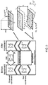
- Figs. 1a)-1c illustrate basic phenomena occurring when tilting a sample on the displacement ( ⁇ ) of the points at different distances from a plane in images acquired from the sample surface at different angles.
- the magnitude of the displacement ( ⁇ ) of each point between its position in one image and its position in the other image acquired from the sample surface held at a different angle depends on the value of the z coordinates of the points (cf. situations a, b and c in Fig. 1 ).
- the z coordinates of these points can be determined.
- Determination of these displacements of the positions of corresponding points between different images can for instance be carried out by conventional 2D digital image correlation (DIC) (see e.g. B. Pan et al., Meas. Sci. Technol. 20 (2009) 062001 ) between the images before and after the tilting.
- DIC 2D digital image correlation
- An image can be considered as a matrix of data in which each pixel is characterized by its position ( x and y coordinates) and a grayscale intensity.
- each pixel is characterized by its position ( x and y coordinates) and a grayscale intensity.
- the modification of coordinates before and after the tilting (situations labeled A and B, respectively) can be described as a combination of rotations and translations (see Figure 2 ).
- [R] is the rotation matrix:
- This plane can be characterized by a vector located at the origin normal to the plane with components ⁇ p z 1 + p x 2 + p y 2 p x , p y , ⁇ 1 .
- Another optical effect that may be considered is a consequence of a translation t z during the movement of the sample.
- the working distance can decrease or increase.
- the final image may be slightly expanded or contracted, respectively, by a factor ⁇ in comparison to the initial image.
- the optical effect of the translation t z during the movement of the sample can be considered to be a uniform effect, while ⁇ z i ⁇ WD and t z ⁇ WD.
- ⁇ z i ⁇ WD and t z ⁇ WD For instance, at a working distance of 9 mm with an error of 0.1% (i.e. 9 ⁇ m), an uncertainty of 30 nm will be obtained in an image of 30 ⁇ 30 microns. If the image resolution is 1000 x1000 pixels, then the pixel size is 30 nm, which is close to the uncertainty range. Actually, this value is quite large, since DIC displacements are calculated at sub pixel regime.
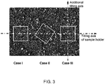
- Case I the images were taken with the x axis of the image essentially parallel (within experimental constraints) to the tilting axis.
- Case II the images were scanned in a direction at an angle of about 35° relative to the tilting axis (see Fig. 3 ).
- Case III the sample was not tilted to different degrees about the same axis, but first tilted about an axis substantially in x direction and subsequently tilted about a second tilting axis substantially perpendicular to the x axis.
- images have been captured with the sample tilted to several nominal tilt angles ( ⁇ nom ) between 0.5 and 12°).
- the images obtained after tilting were compared by DIC with the initial image before movement.
- the influence of the optics considered in this example is a factor ⁇ that multiplies the real coordinates after the movement in order to reach the observed ones.
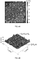
- Fig. 4a shows an illustrative example of a map of DIC displacements in y direction from Case II and Fig. 4b ) shows a fitting performed using eq. 16b.
- the displacements of the points appear distributed in a diagonal manner, in a direction perpendicular to the axis of tilt.
- the deviation of the displacement of each point from the displacement of a corresponding point on the average plane described by the set of Q's depends on ⁇ , on a rotation term and on ⁇ z i .
- the tilt about the x -axis causes most of the dispersion and variation due to differences in z -coordinate values to be expressed in deviation of each point from the diagonal line for both ⁇ y , while just noise appears in the direction of the x axis, as in Case I.
- the tilt about the y axis shows the opposite behavior, with most of the dispersion and variation due to differences in z -coordinate values to be expressed in deviation of each point from the diagonal line for both ⁇ x and only noise in the direction of the y axis.
- the sets of points within a 'family of solutions' form corresponding 3D maps with different z scales.
- This degree of freedom can be eliminated by including a third SEM image C and (in addition to the DIC set AB) a DIC set AC representing the displacements of corresponding points between image A and a third image C.
- three parameters are dependent on the starting situation A only: the plane parameters p x and p y and the sample topography ⁇ z i (see eq. 5). Therefore, by including another DIC set AC, we introduce only one more degree of freedom similar to the one in the AB set, but we also introduce three additional constraints. As a consequence, we can eliminate all unknown parameters from the evaluations of the DIC sets AB and AC. In fact, a redundancy is obtained that allows two methods to reach a unique solution.
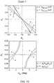
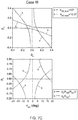
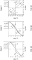
- Such representations are depicted in the top graphs of Figs 7a)-7c ). In each Case, the graph shows two crossing points, which actually represent the same solution for positive or negative reconstructions of the 3D topography.
- Case I does not make a big difference in this respect (cf. Case II in Figure 7 ), since also in this situation information is derived only from different amounts of displacement in a single common direction. Nevertheless, since typical sample holders for SEM apparatus only allow tilting about one axis of rotation, it is relevant for practice that also from images scanned from a sample in a starting position and from that sample tilted to different degrees about the same axis, a quantitative representation of the surface topography of practically meaningful accuracy can obtained.
- the rotation vector can be expressed in the new set of coordinates with the use of eq. 24, i.e. ( a k , a l , a z ) instead of ( a x , a y , a z ).
- p k p x cos ⁇ ABC + p y sin ⁇ ABC
- p l ⁇ p x sin ⁇ ABC + p y cos ⁇ ABC
- this change of coordinate system allows concentrating the topographical information in the direction of one of the axes, e.g. the k axis, and minimizing all information other than noise in the direction of the other axis, e.g. the l axis, as shown in Figure 6b ).
- eq. 17 in the k direction we can get one expression equivalent to eq. 17 in the k direction by using eq. 24a (and in the l direction using eq.
- the topographical information is stored in the ratio of two rotation terms.
- the new coordinate system has been defined in such a way that most of the topographical information is in the k direction.
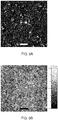
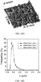
- Figure 9f shows histograms of the images presented in Figure 9c) to 9e ).
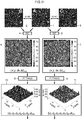
- FIG. 11 A schematic representation of an example of an algorithm for performing a method according to the invention for obtaining a 3D reconstruction of quantitative three-dimensional surface topography data of a sample is shown in Fig. 11 .
- steps 4 and 5 data representing three different images 1, 2, 3 (named A, B, C) scanned from the same sample surface held at different tilts are compared pairwise, resulting in two sets of DIC data 6, 7.
- steps 8 and 9 these sets DIC data 6, 7 are each fitted to two fitting planes, resulting in data sets 10, 11 representing fitting parameters ⁇ q ⁇ 1-6 and ⁇ as well as the data ⁇ x and ⁇ y.
- the expansion parameter ⁇ is calculated in steps 12 and 13 and the ratio a x / a y is quantified, leaving one degree of freedom in each set of fitted data 14, 15.
- step 16 by combining the parameters 14, 15 obtained by fitting of the two sets of DIC data 6, 7 and compensating for expansion and/or contraction, unique solutions 17, 18 for each of the rotations AB and AC are obtained.
- two 3D reconstructions 19, 20 are calculated (one per DIC). In other words, the uncertainty about the z scale that remains when considering only one DIC set 6 or 7 is eliminated by adding a third image, so that the need of complex calibration procedures for determining the precise amount and axis or axes of rotation is avoided.
- a method to correct the perspective distortions is described with reference to a flow chart of an example of an algorithm for performing this method, shown in Fig. 12 .
- the measured displacements as for instance obtained from the DICs result from two effects: the movement of the sample and the manner of observation of the sample.
- the perspective distortion can be corrected to obtain the real coordinates of the sample with the help of eq. 7.
- the process starts with the [x,y,z] data 19 or 20 obtained from the method shown in Fig. 11 , which corresponds to an observation of the sample in an orientation as in situation A (for instance, an average of both 3D profiles 19, 20 is used).
- eq. 7 is used to calculate a first iteration of the real coordinates 22 connected to the observed coordinates in situation A.
- the further steps are for checking the accuracy of the iteration and initiating a further iteration if the accuracy does not meet a predetermined level.
- Steps 23, 24 consist of calculation of the real coordinates 25, 26 in the tilted positions B and C (images 2 and 3 in Fig. 11 ) corresponding with the first iteration 22, using the movement parameters 17, 18 (see Fig. 11 ) obtained before.
- steps 27-29 the perspective distortion for the three different situations is calculated, resulting in new sets 30-32 of coordinates for the monitored points for the situations A, B and C.
- steps 33, 34 new sets of displacement data 35, 36 are determined from these coordinates by subtraction.
- the new sets of displacement data can be regarded as a 'new DIC'.
- decision step 37 if this 'new DIC' matches the observed DIC to a sufficient extent, the calculated set of the real coordinates 22 is accepted as being correct. If not, the 3D algorithm (i.e. starting with steps 8 and 9) shown in Fig. 11 is employed on the new [x,y, ⁇ x, ⁇ y] values to obtain new sets of [x,y,z] according to steps 19 and 20. This cycle continues until a predetermined extent of agreement between the 'new DICs' and the DIC obtained directly from the images has been achieved.
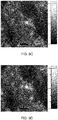
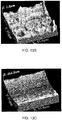
- FIG. 13a An illustration of the effect of the correction for perspective distortions is depicted in Figs. 13a)-13c ) in which Fig. 13a ) shows an image with a larger field of view than the image on which the previous examples of application were based. Its 3D reconstruction with correction for perspective distortion is shown in Fig. 13b ) and the perspective correction used to reach that reconstruction is depicted in Fig. 13c ).
- the 'U' shape of the perspective correction in the y axis is a consequence of the tilting around a rotation axis close to the x axis. It can be seen that, although the perspective correction is smaller than the topography of the sample, its magnitude is important in certain situations.
- the images can be acquired in various manners, for a useful determination of surface topography, variations in tint and or color in the images should allow corresponding points in the images to be identified with a sufficiently fine distribution to recognize topographical features, such as peaks, ridges and valleys, with a resolution that is sufficient for the desired level of detail at which the surface topography is to be determined.
Landscapes
- Engineering & Computer Science (AREA)
- Computer Vision & Pattern Recognition (AREA)
- Physics & Mathematics (AREA)
- General Physics & Mathematics (AREA)
- Theoretical Computer Science (AREA)
- Image Processing (AREA)
- Image Analysis (AREA)
Claims (9)
- Procédé pour déterminer un jeu de données de topographie de surface tridimensionnelles quantitatives à partir d'images obtenues par microscopie, comprenant :l'entrée de données représentant au moins trois images obtenues par microscopie à partir d'une surface d'un échantillon dans un processeur de données, chaque image ayant été acquise à partir de la surface, la surface étant positionnée dans une orientation différente dans le microscope par rapport à un axe optique ou un axe de balayage central du microscope ;le processeur de données déterminant au moins un premier jeu de déplacements de points correspondants entre une première image et une deuxième image, et un deuxième jeu de déplacements de points correspondants entre la première image et une troisième image ;le processeur de données ajustant des composantes directionnelles dans deux directions dudit premier jeu de déplacements à deux plans d'ajustement respectifs, chacun desdits plans d'ajustement étant défini par des paramètres de ce plan d'ajustement respectif, et calculant, à partir desdites composantes directionnelles dans chacune desdites deux directions, les déplacements relatifs desdits points correspondants, chacun desdits déplacements relatifs indiquant une différence entre le déplacement de l'un desdits points correspondants et un déplacement calculé d'un point correspondant sur le plan d'ajustement respectif ;le processeur de données ajustant des composantes directionnelles dans deux directions dudit deuxième jeu de déplacements à deux autres plans d'ajustement respectifs, chacun desdits autres plans d'ajustement étant défini par des paramètres de cet autre plan d'ajustement respectif, et calculant, à partir desdites composantes directionnelles dans chacune desdites deux directions, les déplacements relatifs desdits points correspondants, chacun desdits déplacements relatifs indiquant une différence entre le déplacement de l'un desdits points correspondants et un déplacement calculé d'un point correspondant sur l'autre plan d'ajustement respectif ;le processeur de données calculant une orientation d'un plan d'échantillon pour chaque image et l'angle et l'axe de rotation du plan d'échantillon par rapport à l'axe de balayage central ou optique à partir des paramètres des plans d'ajustement en requérant que, pour au moins deux types de paramètres physiques, tels que l'orientation du plan d'échantillon dans la première image et les distances desdits points correspondants au plan d'échantillon, la valeur résultant dudit premier jeu de déplacements soit identique à la valeur résultant dudit deuxième jeu de déplacements ; etle processeur de données calculant au moins un jeu de données de topographie de surface tridimensionnelles quantitatives à partir de l'orientation calculée du plan d'échantillon pour chaque image et l'angle et l'axe de rotation du plan d'échantillon et au moins lesdits premiers ou deuxièmes déplacements relatifs.
- Procédé selon la revendication 1, dans lequel, durant l'acquisition des images, le plan d'échantillon est à une distance de travail des optiques de balayage ou de focalisation, et dans lequel les paramètres définissant les plans d'ajustement sont utilisés pour calculer des paramètres d'expansion/contraction représentant une expansion ou contraction d'image globale du fait de changements de la distance de travail entre la distance de travail durant l'acquisition de la première image et la distance de travail durant l'acquisition de la deuxième image, et entre la distance de travail durant l'acquisition de la première image et la distance de travail durant l'acquisition de la troisième image.
- Procédé selon la revendication 1 ou 2, dans lequel l'ajustement de chacun des jeux de déplacements à deux plans d'ajustement comprend la détermination de la direction dans laquelle la plus forte variation des déplacements relatifs est trouvée.
- Procédé selon l'une quelconque des revendications précédentes, comprenant en outre le calcul de différences entre des emplacements et les déplacements mesurés à partir d'une perspective centrique et des emplacements et les déplacements dans des coordonnées de laboratoire à partir des données de topographie de surface calculées, de l'orientation calculée du plan d'échantillon, et de la rotation calculée de l'échantillon.
- Procédé selon la revendication 4, comprenant en outre une procédure itérative compensant des différences entre les emplacements et les déplacements mesurés à partir d'une perspective centrique et les emplacements et les déplacements dans des coordonnées de laboratoire sur la base des données de topographie de surface calculées, de l'orientation calculée du plan d'échantillon, et de la rotation calculée de l'échantillon.
- Procédé selon l'une quelconque des revendications précédentes, dans lequel la détermination des jeux de déplacements est effectuée par une corrélation numérique d'images bidimensionnelles (DIC).
- Procédé pour déterminer un jeu de données de topographie de surface tridimensionnelles quantitatives à partir d'une surface d'échantillon, comprenant :le positionnement d'une surface d'échantillon dans un microscope dans une première position et l'obtention de données représentant une première image de cette surface d'échantillon ;le positionnement de la surface d'échantillon dans le microscope dans une deuxième position inclinée par rapport à la première position et l'obtention de données représentant une deuxième image de cette surface d'échantillon ;le positionnement de la surface d'échantillon dans le microscope dans une troisième position inclinée par rapport à la première position et l'obtention de données représentant une troisième image de cette surface d'échantillon ; etun procédé selon l'une quelconque des revendications précédentes pour déterminer un jeu de données de topographie de surface tridimensionnelles quantitatives à partir desdites images.
- Produit de type programme informatique sous une forme exécutable par ordinateur pour déterminer un jeu de données de topographie de surface tridimensionnelles quantitatives à partir d'images obtenues par microscopie, comprenant :des instructions pour accéder à des données représentant au moins trois images obtenues par microscopie à partir d'une surface d'un échantillon dans un processeur de données, chaque image ayant été acquise à partir de la surface, la surface étant positionnée dans une orientation différente dans le microscope par rapport à un axe optique ou un axe de balayage central du microscope ;des instructions déterminant au moins un premier jeu de déplacements de points correspondants entre une première image et une deuxième image, et un deuxième jeu de déplacements de points correspondants entre la première image et une troisième image ;des instructions pour ajuster des composantes directionnelles dans deux directions dudit premier jeu de déplacements à deux plans d'ajustement respectifs, chacun desdits plans d'ajustement étant défini par des paramètres de ce plan d'ajustement respectif, et calculer, à partir desdites composantes directionnelles dans chacune desdites deux directions, les déplacements relatifs desdits points correspondants, chacun desdits déplacements relatifs indiquant une différence entre le déplacement de l'un desdits points correspondants et un déplacement calculé d'un point correspondant sur le plan d'ajustement respectif ;des instructions pour ajuster des composantes directionnelles dans deux directions dudit deuxième jeu de déplacements à deux autres plans d'ajustement respectifs, chacun desdits autres plans d'ajustement étant défini par des paramètres de cet autre plan d'ajustement respectif, et calculer, à partir desdites composantes directionnelles dans chacune desdites deux directions, les déplacements relatifs desdits points correspondants, chacun desdits déplacements relatifs indiquant une différence entre le déplacement de l'un desdits points correspondants et un déplacement calculé d'un point correspondant sur l'autre plan d'ajustement respectif ;des instructions pour calculer une orientation d'un plan d'échantillon pour chaque image et l'angle et l'axe de rotation du plan d'échantillon par rapport à l'axe de balayage central ou optique à partir des paramètres des plans d'ajustement en requérant que, pour au moins deux types de paramètres physiques, tels que l'orientation du plan d'échantillon dans la première image et les distances desdits points correspondants au plan d'échantillon, la valeur résultant dudit premier jeu de déplacements soit identique à la valeur résultant dudit deuxième jeu de déplacements ; etdes instructions pour calculer au moins un jeu de données de topographie de surface tridimensionnelles quantitatives à partir de l'orientation calculée du plan d'échantillon pour chaque image et l'angle et l'axe de rotation du plan d'échantillon et au moins lesdits premiers ou deuxièmes déplacements relatifs.
- Produit de type programme informatique selon la revendication 8, stocké sur un support de stockage de données non transitoire.
Applications Claiming Priority (2)
| Application Number | Priority Date | Filing Date | Title |
|---|---|---|---|
| EP14170815 | 2014-06-02 | ||
| PCT/EP2015/062231 WO2015185538A1 (fr) | 2014-06-02 | 2015-06-02 | Détermination de topographie de surface tridimensionnelle quantitative à partir d'images microscopiques bidimensionnelles |
Publications (2)
| Publication Number | Publication Date |
|---|---|
| EP3149703A1 EP3149703A1 (fr) | 2017-04-05 |
| EP3149703B1 true EP3149703B1 (fr) | 2018-04-04 |
Family
ID=50884267
Family Applications (1)
| Application Number | Title | Priority Date | Filing Date |
|---|---|---|---|
| EP15726952.3A Active EP3149703B1 (fr) | 2014-06-02 | 2015-06-02 | Détermination quantitative de topographie de surface tridimensionnelle à partir des images microscopiques bidimensionnelles |
Country Status (2)
| Country | Link |
|---|---|
| EP (1) | EP3149703B1 (fr) |
| WO (1) | WO2015185538A1 (fr) |
Families Citing this family (1)
| Publication number | Priority date | Publication date | Assignee | Title |
|---|---|---|---|---|
| DE102017100262A1 (de) | 2017-01-09 | 2018-07-12 | Carl Zeiss Microscopy Gmbh | Verfahren zur Erzeugung eines dreidimensionalen Modells einer Probe in einem digitalen Mikroskop und digitales Mikroskop |
-
2015
- 2015-06-02 WO PCT/EP2015/062231 patent/WO2015185538A1/fr not_active Ceased
- 2015-06-02 EP EP15726952.3A patent/EP3149703B1/fr active Active
Also Published As
| Publication number | Publication date |
|---|---|
| EP3149703A1 (fr) | 2017-04-05 |
| WO2015185538A1 (fr) | 2015-12-10 |
Similar Documents
| Publication | Publication Date | Title |
|---|---|---|
| EP0641021B1 (fr) | Analyse de particules de plaquettes entaillées | |
| JP5178692B2 (ja) | 試料の観察方法 | |
| Mello et al. | Distortion correction protocol for digital image correlation after scanning electron microscopy: emphasis on long duration and ex-situ experiments | |
| JP6152077B2 (ja) | 走査電子顕微鏡画像を用いた3次元マッピング | |
| Zhu et al. | Quantitative stereovision in a scanning electron microscope | |
| Cabezas et al. | A new method of image processing in the analysis of axisymmetric drop shapes | |
| JP4500099B2 (ja) | 電子顕微鏡装置システム及び電子顕微鏡装置システムを用いた寸法計測方法 | |
| TWI826123B (zh) | 以更高的精度對半導體晶圓進行3d體積檢測的方法和檢測系統 | |
| US20090039285A1 (en) | Method and device for controlling and monitoring a position of a holding element | |
| JP4500653B2 (ja) | 試料の観察方法及びその装置 | |
| Lockwood et al. | Use and verification of digital image correlation for automated 3-D surface characterization in the scanning electron microscope | |
| Emelyanenko et al. | Application of dynamic thresholding of video images for measuring the interfacial tension of liquids and contact angles | |
| US20160322191A1 (en) | Methods, systems, and computer readable media for measuring and correcting drift distortion in images obtained using a scanning microscope | |
| Liu et al. | A novel method to calibrate the rotation axis of a line-structured light 3-dimensional measurement system | |
| Neggers et al. | Principal image decomposition for multi-detector backscatter electron topography reconstruction | |
| TW201723422A (zh) | 光滑物體的量測系統及其量測方法 | |
| Chen et al. | Digital image correlation of SEM images for surface deformation of CMOS IC | |
| Díez et al. | Tilt-series and electron microscope alignment for the correction of the non-perpendicularity of beam and tilt-axis | |
| JP7393737B2 (ja) | 画像検査装置及び画像検査方法 | |
| Jolley et al. | Correlative X-ray computed tomography and optical microscopy serial sectioning data of additive manufactured ti-6Al-4V | |
| EP3149703B1 (fr) | Détermination quantitative de topographie de surface tridimensionnelle à partir des images microscopiques bidimensionnelles | |
| JP5481883B2 (ja) | 特定部位検出方法を用いた試料分析装置 | |
| Tondare | A concept for three-dimensional particle metrology based on scanning electron microscopy and structure-from-motion photogrammetry | |
| Faber et al. | Calibration-free quantitative surface topography reconstruction in scanning electron microscopy | |
| Chen | Data fusion for accurate microscopic rough surface metrology |
Legal Events
| Date | Code | Title | Description |
|---|---|---|---|
| PUAI | Public reference made under article 153(3) epc to a published international application that has entered the european phase |
Free format text: ORIGINAL CODE: 0009012 |
|
| 17P | Request for examination filed |
Effective date: 20161230 |
|
| AK | Designated contracting states |
Kind code of ref document: A1 Designated state(s): AL AT BE BG CH CY CZ DE DK EE ES FI FR GB GR HR HU IE IS IT LI LT LU LV MC MK MT NL NO PL PT RO RS SE SI SK SM TR |
|
| AX | Request for extension of the european patent |
Extension state: BA ME |
|
| DAV | Request for validation of the european patent (deleted) | ||
| DAX | Request for extension of the european patent (deleted) | ||
| REG | Reference to a national code |
Ref country code: DE Ref legal event code: R079 Ref document number: 602015009613 Country of ref document: DE Free format text: PREVIOUS MAIN CLASS: G06T0007000000 Ipc: G06T0007593000 |
|
| RIC1 | Information provided on ipc code assigned before grant |
Ipc: G06T 7/593 20170101AFI20170913BHEP |
|
| GRAP | Despatch of communication of intention to grant a patent |
Free format text: ORIGINAL CODE: EPIDOSNIGR1 |
|
| INTG | Intention to grant announced |
Effective date: 20171023 |
|
| GRAS | Grant fee paid |
Free format text: ORIGINAL CODE: EPIDOSNIGR3 |
|
| GRAA | (expected) grant |
Free format text: ORIGINAL CODE: 0009210 |
|
| AK | Designated contracting states |
Kind code of ref document: B1 Designated state(s): AL AT BE BG CH CY CZ DE DK EE ES FI FR GB GR HR HU IE IS IT LI LT LU LV MC MK MT NL NO PL PT RO RS SE SI SK SM TR |
|
| REG | Reference to a national code |
Ref country code: GB Ref legal event code: FG4D |
|
| REG | Reference to a national code |
Ref country code: CH Ref legal event code: EP |
|
| REG | Reference to a national code |
Ref country code: AT Ref legal event code: REF Ref document number: 986363 Country of ref document: AT Kind code of ref document: T Effective date: 20180415 |
|
| REG | Reference to a national code |
Ref country code: IE Ref legal event code: FG4D |
|
| REG | Reference to a national code |
Ref country code: DE Ref legal event code: R096 Ref document number: 602015009613 Country of ref document: DE |
|
| REG | Reference to a national code |
Ref country code: FR Ref legal event code: PLFP Year of fee payment: 4 |
|
| REG | Reference to a national code |
Ref country code: NL Ref legal event code: FP |
|
| REG | Reference to a national code |
Ref country code: LT Ref legal event code: MG4D |
|
| PG25 | Lapsed in a contracting state [announced via postgrant information from national office to epo] |
Ref country code: NO Free format text: LAPSE BECAUSE OF FAILURE TO SUBMIT A TRANSLATION OF THE DESCRIPTION OR TO PAY THE FEE WITHIN THE PRESCRIBED TIME-LIMIT Effective date: 20180704 Ref country code: BG Free format text: LAPSE BECAUSE OF FAILURE TO SUBMIT A TRANSLATION OF THE DESCRIPTION OR TO PAY THE FEE WITHIN THE PRESCRIBED TIME-LIMIT Effective date: 20180704 Ref country code: LT Free format text: LAPSE BECAUSE OF FAILURE TO SUBMIT A TRANSLATION OF THE DESCRIPTION OR TO PAY THE FEE WITHIN THE PRESCRIBED TIME-LIMIT Effective date: 20180404 Ref country code: FI Free format text: LAPSE BECAUSE OF FAILURE TO SUBMIT A TRANSLATION OF THE DESCRIPTION OR TO PAY THE FEE WITHIN THE PRESCRIBED TIME-LIMIT Effective date: 20180404 Ref country code: AL Free format text: LAPSE BECAUSE OF FAILURE TO SUBMIT A TRANSLATION OF THE DESCRIPTION OR TO PAY THE FEE WITHIN THE PRESCRIBED TIME-LIMIT Effective date: 20180404 Ref country code: ES Free format text: LAPSE BECAUSE OF FAILURE TO SUBMIT A TRANSLATION OF THE DESCRIPTION OR TO PAY THE FEE WITHIN THE PRESCRIBED TIME-LIMIT Effective date: 20180404 Ref country code: SE Free format text: LAPSE BECAUSE OF FAILURE TO SUBMIT A TRANSLATION OF THE DESCRIPTION OR TO PAY THE FEE WITHIN THE PRESCRIBED TIME-LIMIT Effective date: 20180404 Ref country code: PL Free format text: LAPSE BECAUSE OF FAILURE TO SUBMIT A TRANSLATION OF THE DESCRIPTION OR TO PAY THE FEE WITHIN THE PRESCRIBED TIME-LIMIT Effective date: 20180404 |
|
| PG25 | Lapsed in a contracting state [announced via postgrant information from national office to epo] |
Ref country code: HR Free format text: LAPSE BECAUSE OF FAILURE TO SUBMIT A TRANSLATION OF THE DESCRIPTION OR TO PAY THE FEE WITHIN THE PRESCRIBED TIME-LIMIT Effective date: 20180404 Ref country code: LV Free format text: LAPSE BECAUSE OF FAILURE TO SUBMIT A TRANSLATION OF THE DESCRIPTION OR TO PAY THE FEE WITHIN THE PRESCRIBED TIME-LIMIT Effective date: 20180404 Ref country code: GR Free format text: LAPSE BECAUSE OF FAILURE TO SUBMIT A TRANSLATION OF THE DESCRIPTION OR TO PAY THE FEE WITHIN THE PRESCRIBED TIME-LIMIT Effective date: 20180705 Ref country code: RS Free format text: LAPSE BECAUSE OF FAILURE TO SUBMIT A TRANSLATION OF THE DESCRIPTION OR TO PAY THE FEE WITHIN THE PRESCRIBED TIME-LIMIT Effective date: 20180404 |
|
| REG | Reference to a national code |
Ref country code: AT Ref legal event code: MK05 Ref document number: 986363 Country of ref document: AT Kind code of ref document: T Effective date: 20180404 |
|
| PG25 | Lapsed in a contracting state [announced via postgrant information from national office to epo] |
Ref country code: PT Free format text: LAPSE BECAUSE OF FAILURE TO SUBMIT A TRANSLATION OF THE DESCRIPTION OR TO PAY THE FEE WITHIN THE PRESCRIBED TIME-LIMIT Effective date: 20180806 |
|
| REG | Reference to a national code |
Ref country code: DE Ref legal event code: R097 Ref document number: 602015009613 Country of ref document: DE |
|
| PG25 | Lapsed in a contracting state [announced via postgrant information from national office to epo] |
Ref country code: AT Free format text: LAPSE BECAUSE OF FAILURE TO SUBMIT A TRANSLATION OF THE DESCRIPTION OR TO PAY THE FEE WITHIN THE PRESCRIBED TIME-LIMIT Effective date: 20180404 Ref country code: EE Free format text: LAPSE BECAUSE OF FAILURE TO SUBMIT A TRANSLATION OF THE DESCRIPTION OR TO PAY THE FEE WITHIN THE PRESCRIBED TIME-LIMIT Effective date: 20180404 Ref country code: CZ Free format text: LAPSE BECAUSE OF FAILURE TO SUBMIT A TRANSLATION OF THE DESCRIPTION OR TO PAY THE FEE WITHIN THE PRESCRIBED TIME-LIMIT Effective date: 20180404 Ref country code: RO Free format text: LAPSE BECAUSE OF FAILURE TO SUBMIT A TRANSLATION OF THE DESCRIPTION OR TO PAY THE FEE WITHIN THE PRESCRIBED TIME-LIMIT Effective date: 20180404 Ref country code: SK Free format text: LAPSE BECAUSE OF FAILURE TO SUBMIT A TRANSLATION OF THE DESCRIPTION OR TO PAY THE FEE WITHIN THE PRESCRIBED TIME-LIMIT Effective date: 20180404 Ref country code: DK Free format text: LAPSE BECAUSE OF FAILURE TO SUBMIT A TRANSLATION OF THE DESCRIPTION OR TO PAY THE FEE WITHIN THE PRESCRIBED TIME-LIMIT Effective date: 20180404 |
|
| PLBE | No opposition filed within time limit |
Free format text: ORIGINAL CODE: 0009261 |
|
| STAA | Information on the status of an ep patent application or granted ep patent |
Free format text: STATUS: NO OPPOSITION FILED WITHIN TIME LIMIT |
|
| PG25 | Lapsed in a contracting state [announced via postgrant information from national office to epo] |
Ref country code: SM Free format text: LAPSE BECAUSE OF FAILURE TO SUBMIT A TRANSLATION OF THE DESCRIPTION OR TO PAY THE FEE WITHIN THE PRESCRIBED TIME-LIMIT Effective date: 20180404 Ref country code: IT Free format text: LAPSE BECAUSE OF FAILURE TO SUBMIT A TRANSLATION OF THE DESCRIPTION OR TO PAY THE FEE WITHIN THE PRESCRIBED TIME-LIMIT Effective date: 20180404 |
|
| 26N | No opposition filed |
Effective date: 20190107 |
|
| PG25 | Lapsed in a contracting state [announced via postgrant information from national office to epo] |
Ref country code: MC Free format text: LAPSE BECAUSE OF FAILURE TO SUBMIT A TRANSLATION OF THE DESCRIPTION OR TO PAY THE FEE WITHIN THE PRESCRIBED TIME-LIMIT Effective date: 20180404 Ref country code: LU Free format text: LAPSE BECAUSE OF NON-PAYMENT OF DUE FEES Effective date: 20180602 |
|
| PG25 | Lapsed in a contracting state [announced via postgrant information from national office to epo] |
Ref country code: SI Free format text: LAPSE BECAUSE OF FAILURE TO SUBMIT A TRANSLATION OF THE DESCRIPTION OR TO PAY THE FEE WITHIN THE PRESCRIBED TIME-LIMIT Effective date: 20180404 |
|
| PG25 | Lapsed in a contracting state [announced via postgrant information from national office to epo] |
Ref country code: MT Free format text: LAPSE BECAUSE OF NON-PAYMENT OF DUE FEES Effective date: 20180602 |
|
| PG25 | Lapsed in a contracting state [announced via postgrant information from national office to epo] |
Ref country code: TR Free format text: LAPSE BECAUSE OF FAILURE TO SUBMIT A TRANSLATION OF THE DESCRIPTION OR TO PAY THE FEE WITHIN THE PRESCRIBED TIME-LIMIT Effective date: 20180404 |
|
| PG25 | Lapsed in a contracting state [announced via postgrant information from national office to epo] |
Ref country code: MK Free format text: LAPSE BECAUSE OF NON-PAYMENT OF DUE FEES Effective date: 20180404 Ref country code: HU Free format text: LAPSE BECAUSE OF FAILURE TO SUBMIT A TRANSLATION OF THE DESCRIPTION OR TO PAY THE FEE WITHIN THE PRESCRIBED TIME-LIMIT; INVALID AB INITIO Effective date: 20150602 Ref country code: CY Free format text: LAPSE BECAUSE OF FAILURE TO SUBMIT A TRANSLATION OF THE DESCRIPTION OR TO PAY THE FEE WITHIN THE PRESCRIBED TIME-LIMIT Effective date: 20180404 |
|
| PG25 | Lapsed in a contracting state [announced via postgrant information from national office to epo] |
Ref country code: IS Free format text: LAPSE BECAUSE OF FAILURE TO SUBMIT A TRANSLATION OF THE DESCRIPTION OR TO PAY THE FEE WITHIN THE PRESCRIBED TIME-LIMIT Effective date: 20180804 |
|
| P01 | Opt-out of the competence of the unified patent court (upc) registered |
Effective date: 20230504 |
|
| PGFP | Annual fee paid to national office [announced via postgrant information from national office to epo] |
Ref country code: DE Payment date: 20230620 Year of fee payment: 9 |
|
| PGFP | Annual fee paid to national office [announced via postgrant information from national office to epo] |
Ref country code: NL Payment date: 20240521 Year of fee payment: 10 |
|
| PGFP | Annual fee paid to national office [announced via postgrant information from national office to epo] |
Ref country code: IE Payment date: 20240619 Year of fee payment: 10 |
|
| PGFP | Annual fee paid to national office [announced via postgrant information from national office to epo] |
Ref country code: GB Payment date: 20240621 Year of fee payment: 10 |
|
| PGFP | Annual fee paid to national office [announced via postgrant information from national office to epo] |
Ref country code: FR Payment date: 20240628 Year of fee payment: 10 |
|
| PGFP | Annual fee paid to national office [announced via postgrant information from national office to epo] |
Ref country code: BE Payment date: 20240619 Year of fee payment: 10 |
|
| PGFP | Annual fee paid to national office [announced via postgrant information from national office to epo] |
Ref country code: CH Payment date: 20240701 Year of fee payment: 10 |
|
| REG | Reference to a national code |
Ref country code: DE Ref legal event code: R119 Ref document number: 602015009613 Country of ref document: DE |
|
| REG | Reference to a national code |
Ref country code: CH Ref legal event code: H13 Free format text: ST27 STATUS EVENT CODE: U-0-0-H10-H13 (AS PROVIDED BY THE NATIONAL OFFICE) Effective date: 20260127 |
|
| REG | Reference to a national code |
Ref country code: NL Ref legal event code: MM Effective date: 20250701 |
|
| GBPC | Gb: european patent ceased through non-payment of renewal fee |
Effective date: 20250602 |
|
| REG | Reference to a national code |
Ref country code: BE Ref legal event code: MM Effective date: 20250630 |
|
| PG25 | Lapsed in a contracting state [announced via postgrant information from national office to epo] |
Ref country code: NL Free format text: LAPSE BECAUSE OF NON-PAYMENT OF DUE FEES Effective date: 20250701 |
|
| PG25 | Lapsed in a contracting state [announced via postgrant information from national office to epo] |
Ref country code: GB Free format text: LAPSE BECAUSE OF NON-PAYMENT OF DUE FEES Effective date: 20250602 |
|
| PG25 | Lapsed in a contracting state [announced via postgrant information from national office to epo] |
Ref country code: IE Free format text: LAPSE BECAUSE OF NON-PAYMENT OF DUE FEES Effective date: 20250602 Ref country code: DE Free format text: LAPSE BECAUSE OF NON-PAYMENT OF DUE FEES Effective date: 20260101 |
|
| PG25 | Lapsed in a contracting state [announced via postgrant information from national office to epo] |
Ref country code: BE Free format text: LAPSE BECAUSE OF NON-PAYMENT OF DUE FEES Effective date: 20250630 |
|
| PG25 | Lapsed in a contracting state [announced via postgrant information from national office to epo] |
Ref country code: FR Free format text: LAPSE BECAUSE OF NON-PAYMENT OF DUE FEES Effective date: 20250630 |
|
| PG25 | Lapsed in a contracting state [announced via postgrant information from national office to epo] |
Ref country code: CH Free format text: LAPSE BECAUSE OF NON-PAYMENT OF DUE FEES Effective date: 20250630 |