EP3149825B1 - Reaktive leistungsvorhersagefähigkeit - Google Patents
Reaktive leistungsvorhersagefähigkeit Download PDFInfo
- Publication number
- EP3149825B1 EP3149825B1 EP14893594.3A EP14893594A EP3149825B1 EP 3149825 B1 EP3149825 B1 EP 3149825B1 EP 14893594 A EP14893594 A EP 14893594A EP 3149825 B1 EP3149825 B1 EP 3149825B1
- Authority
- EP
- European Patent Office
- Prior art keywords
- reactive power
- grid
- capability
- maximum reactive
- lead
- Prior art date
- Legal status (The legal status is an assumption and is not a legal conclusion. Google has not performed a legal analysis and makes no representation as to the accuracy of the status listed.)
- Active
Links
Images





Classifications
-
- H—ELECTRICITY
- H02—GENERATION; CONVERSION OR DISTRIBUTION OF ELECTRIC POWER
- H02J—ELECTRIC POWER NETWORKS; CIRCUIT ARRANGEMENTS OR SYSTEMS FOR SUPPLYING OR DISTRIBUTING ELECTRIC POWER; SYSTEMS FOR STORING ELECTRIC ENERGY
- H02J3/00—Circuit arrangements for AC mains or AC distribution networks
- H02J3/18—Arrangements for adjusting, eliminating or compensating reactive power in networks
-
- G—PHYSICS
- G05—CONTROLLING; REGULATING
- G05B—CONTROL OR REGULATING SYSTEMS IN GENERAL; FUNCTIONAL ELEMENTS OF SUCH SYSTEMS; MONITORING OR TESTING ARRANGEMENTS FOR SUCH SYSTEMS OR ELEMENTS
- G05B13/00—Adaptive control systems, i.e. systems automatically adjusting themselves to have a performance which is optimum according to some preassigned criterion
- G05B13/02—Adaptive control systems, i.e. systems automatically adjusting themselves to have a performance which is optimum according to some preassigned criterion electric
- G05B13/0205—Adaptive control systems, i.e. systems automatically adjusting themselves to have a performance which is optimum according to some preassigned criterion electric not using a model or a simulator of the controlled system
- G05B13/026—Adaptive control systems, i.e. systems automatically adjusting themselves to have a performance which is optimum according to some preassigned criterion electric not using a model or a simulator of the controlled system using a predictor
-
- H—ELECTRICITY
- H02—GENERATION; CONVERSION OR DISTRIBUTION OF ELECTRIC POWER
- H02P—CONTROL OR REGULATION OF ELECTRIC MOTORS, ELECTRIC GENERATORS OR DYNAMO-ELECTRIC CONVERTERS; CONTROLLING TRANSFORMERS, REACTORS OR CHOKE COILS
- H02P2101/00—Special adaptation of control arrangements for generators
-
- H—ELECTRICITY
- H02—GENERATION; CONVERSION OR DISTRIBUTION OF ELECTRIC POWER
- H02P—CONTROL OR REGULATION OF ELECTRIC MOTORS, ELECTRIC GENERATORS OR DYNAMO-ELECTRIC CONVERTERS; CONTROLLING TRANSFORMERS, REACTORS OR CHOKE COILS
- H02P2207/00—Indexing scheme relating to controlling arrangements characterised by the type of motor
- H02P2207/07—Doubly fed machines receiving two supplies both on the stator only wherein the power supply is fed to different sets of stator windings or to rotor and stator windings
- H02P2207/073—Doubly fed machines receiving two supplies both on the stator only wherein the power supply is fed to different sets of stator windings or to rotor and stator windings wherein only one converter is used, the other windings being supplied without converter, e.g. doubly-fed induction machines
-
- H—ELECTRICITY
- H02—GENERATION; CONVERSION OR DISTRIBUTION OF ELECTRIC POWER
- H02P—CONTROL OR REGULATION OF ELECTRIC MOTORS, ELECTRIC GENERATORS OR DYNAMO-ELECTRIC CONVERTERS; CONTROLLING TRANSFORMERS, REACTORS OR CHOKE COILS
- H02P27/00—Arrangements or methods for the control of AC motors characterised by the kind of supply voltage
- H02P27/04—Arrangements or methods for the control of AC motors characterised by the kind of supply voltage using variable-frequency supply voltage, e.g. inverter or converter supply voltage
- H02P27/06—Arrangements or methods for the control of AC motors characterised by the kind of supply voltage using variable-frequency supply voltage, e.g. inverter or converter supply voltage using DC to AC converters or inverters
-
- Y—GENERAL TAGGING OF NEW TECHNOLOGICAL DEVELOPMENTS; GENERAL TAGGING OF CROSS-SECTIONAL TECHNOLOGIES SPANNING OVER SEVERAL SECTIONS OF THE IPC; TECHNICAL SUBJECTS COVERED BY FORMER USPC CROSS-REFERENCE ART COLLECTIONS [XRACs] AND DIGESTS
- Y02—TECHNOLOGIES OR APPLICATIONS FOR MITIGATION OR ADAPTATION AGAINST CLIMATE CHANGE
- Y02E—REDUCTION OF GREENHOUSE GAS [GHG] EMISSIONS, RELATED TO ENERGY GENERATION, TRANSMISSION OR DISTRIBUTION
- Y02E10/00—Energy generation through renewable energy sources
- Y02E10/50—Photovoltaic [PV] energy
- Y02E10/56—Power conversion systems, e.g. maximum power point trackers
-
- Y—GENERAL TAGGING OF NEW TECHNOLOGICAL DEVELOPMENTS; GENERAL TAGGING OF CROSS-SECTIONAL TECHNOLOGIES SPANNING OVER SEVERAL SECTIONS OF THE IPC; TECHNICAL SUBJECTS COVERED BY FORMER USPC CROSS-REFERENCE ART COLLECTIONS [XRACs] AND DIGESTS
- Y02—TECHNOLOGIES OR APPLICATIONS FOR MITIGATION OR ADAPTATION AGAINST CLIMATE CHANGE
- Y02E—REDUCTION OF GREENHOUSE GAS [GHG] EMISSIONS, RELATED TO ENERGY GENERATION, TRANSMISSION OR DISTRIBUTION
- Y02E10/00—Energy generation through renewable energy sources
- Y02E10/70—Wind energy
- Y02E10/76—Power conversion electric or electronic aspects
-
- Y—GENERAL TAGGING OF NEW TECHNOLOGICAL DEVELOPMENTS; GENERAL TAGGING OF CROSS-SECTIONAL TECHNOLOGIES SPANNING OVER SEVERAL SECTIONS OF THE IPC; TECHNICAL SUBJECTS COVERED BY FORMER USPC CROSS-REFERENCE ART COLLECTIONS [XRACs] AND DIGESTS
- Y02—TECHNOLOGIES OR APPLICATIONS FOR MITIGATION OR ADAPTATION AGAINST CLIMATE CHANGE
- Y02E—REDUCTION OF GREENHOUSE GAS [GHG] EMISSIONS, RELATED TO ENERGY GENERATION, TRANSMISSION OR DISTRIBUTION
- Y02E40/00—Technologies for an efficient electrical power generation, transmission or distribution
- Y02E40/30—Reactive power compensation
-
- Y—GENERAL TAGGING OF NEW TECHNOLOGICAL DEVELOPMENTS; GENERAL TAGGING OF CROSS-SECTIONAL TECHNOLOGIES SPANNING OVER SEVERAL SECTIONS OF THE IPC; TECHNICAL SUBJECTS COVERED BY FORMER USPC CROSS-REFERENCE ART COLLECTIONS [XRACs] AND DIGESTS
- Y02—TECHNOLOGIES OR APPLICATIONS FOR MITIGATION OR ADAPTATION AGAINST CLIMATE CHANGE
- Y02P—CLIMATE CHANGE MITIGATION TECHNOLOGIES IN THE PRODUCTION OR PROCESSING OF GOODS
- Y02P80/00—Climate change mitigation technologies for sector-wide applications
- Y02P80/10—Efficient use of energy, e.g. using compressed air or pressurized fluid as energy carrier
- Y02P80/14—District level solutions, i.e. local energy networks
Definitions
- the present invention relates generally to the electric grid. More specifically, the present invention relates to converters for regulating electricity supplied to the electric grid from an external energy source.
- Grid-tied converters commonly used in association with the electric grid, convert renewable energy into alternating current (AC) format that electric power system can accept.
- grid-tied converters are used to convert energy from an energy source, such as solar panel, wind turbine , or some other source, into an AC format for feeding energy into the grid, based upon a relevant local grid code.
- grid codes are technical specifications defining specific parameters that an external source, or facility, must achieve to connect to the electric grid.
- the specifications ensure compatibility, safety, and security of the supplied electricity.
- power flowing into the electric grid includes two types: active power (P) and reactive power (Q).
- Grid codes differ by country, but one common request is the grid-tied renewable energy converters are generally required to provide a reactive power compensation ability which must be under the control of grid management system, and some grid codes even stress the priority to use the converters' reactive power capability than static VAR compensator when needed.
- Conventional grid-tied converters usually include an ability to provide reactive power compensation.
- Conventional grid-tied converters lack the ability to forecast converters' own reactive power capabilities accurately, to help the grid management system to understand how much the converters can provide in reactive power compensation.
- Patent documents EP 2 164 147 A2 , US 2010/320762 A1 and US 2013/250635 A1 disclose devices and methods for compensation of reactive power.
- an embodiment of the present invention includes a system for regulating energy provided to an electricity grid from an energy source, the system includes a converter configured to receive the energy from the source.
- the converter is configured to dynamically predict real-time maximum reactive power capability as a function of at least one from the group including (i) a direct current link maximum voltage, (ii) an instantaneous grid network voltage, and (iii) a line current.
- the predicted maximum reactive power capability is configured for optimizing regulation of the energy.
- the present invention enables prediction of the power converter's reactive power capability to be more accurate and comprehensive, which helps the grid management system make optimum reactive power compensation strategy.
- maximum Q capability prediction techniques are substantially independent of the grid impedance, which is usually unknown. These techniques accurately predict maximum Q capability as a function of relevant grid codes, internal converter status information, and external grid connection point feedback information.
- FIG. 1 is a block diagram illustration of an exemplary electricity power management system 100, in which embodiments of the present invention may be practiced.
- the system 100 includes an electricity grid 102, along with an energy source 104.
- One such energy source can include a photovoltaic (PV) based solar source providing renewable energy to the electricity grid 102.
- PV photovoltaic
- a grid-tied converter 106 is provided to receive, test, and regulate the energy produced by the energy source 104 to ensure its suitability and compatibility with the electricity grid 102.
- a wind turbine coupled to a permanent magnet synchronous generator (PMSG) can supply wind generated electricity to the grid-tied converter 106.
- the converter 106 will analyze the wind generated electricity, regulate it, ensure its suitability and compatibility as a viable energy source for supply to the electricity grid 102.
- the grid-tied converter 106 regulates the output of energy source 104 to compensate for irregularities, or transient faults, in the electricity output therefrom - irregularities or faults that could ultimately degrade the performance of the electric grid 102.
- the capability to compensate for irregularities, or faults, in the electricity output from external sources is a function of the reactive power capability of the grid-tied converter 106.
- the grid when power is supplied to the grid 102, the grid presents an inherent capacity, which correspondingly means the grid impedance. Additionally, the external environment can produce malfunctions (e.g., impedance/voltage/frequency) of the grid 102 during operation. These malfunctions, ultimately due to short circuits, lightning damage, or other anomalies, can trigger corresponding failures in equipment used to perform vital functions associated with the grid 102.
- malfunctions e.g., impedance/voltage/frequency
- grid-tied converters should possess a capability to accurately predict reactive power capability - regardless of whether during steady-state or transient conditions occur.
- the grid-tied converter 106 possesses the capability to dynamically predict reactive power capability in real-time.
- the grid-tied converter 106 constructed in accordance with the present invention includes a function which can real-time predict the converter's reactive power capability. This prediction capability is based upon status information internal to the grid-tied converter 106 and external connection point feedback information associated with the electric grid 102.
- the capability of the grid-tied converter 106 to accurately predict its own reactive compensation volume provides a more effective fault management system.
- a more accurate assessment of reactive power capability enables more effective regulation of electricity (e.g., voltages) associated with the power management system environment 100. Additionally, when regulation fails to prevent malfunctions, and faults occur, the embodiments accelerate recovery and enhance survivability.
- FIG. 2 is a block diagram illustration of a physical model of the grid-tied converter 106 coupled to the electric grid 102, along with various parameters generally indicative of steady-state (i.e., fault-free) grid operation.
- the grid-tied converter 106 includes a converter control module 200.
- the converter control module 200 includes additional sub-modules and components for optimizing the accuracy of the reactive power capability prediction of the grid-tied converter 106.
- the grid-tied converter 106 produces a power converter instantaneous line voltage Vc.
- An inductor L represents an inductance of the power converter 106, producing a grid current Ig, as Vc flows therethrough, and an instantaneous grid line voltage Vg.
- the interplay between Vc, Vg, Ig, and L is relevant to the Q capability prediction of the grid-tied converter 106.
- the reactive power compensation is a function of Q, which stabilizes the grid voltage Vg, enhancing the operational efficiency of the electricity power management system 100.
- Q can be further divided into two types: lead reactive power (lead Var) and lag reactive power (lag Var).
- FIG. 3 is a graphical illustration 300 of the influence by DC-link maximum voltage (Vdc_max), which is integral to accurately determining lead Var.
- Vdc_max DC-link maximum voltage
- the maximum achievable AC line voltage (Vc_max) of the grid-tied converter 106 is a function of, and physically limited by, Vdc_max.
- FIG. 3 depicts vector relationships determining the maximum lead Var.
- the maximum lead Var is also a function of grid frequency (fg). Assuming the instantaneous grid line voltage is Vg and feed power is Pout, grid capacity is sufficiently large such that Vg will not change during Q compensation.
- the graph 300 depicts a short vector Vc and a longer vector Vc_max.
- the vertical vector V_y remains unchanged, resulting in Pout also remaining unchanged.
- Vc_max Vdc_max ⁇ K (where K is a value that is based on converter's topology), and Pout remains constant, as noted above.
- ⁇ asin V _ y / Vc _ max
- Qvar _ pos _ max _ 1 sqrt 3 ⁇ Vg ⁇ Vc _ max ⁇ cos ⁇ ⁇ Vg / Z
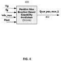
- FIG. 4 is a block diagram illustrating an exemplary lead reactive power capability prediction module 400 configured for dynamically producing an output (Qvar_pos_max_1) 402 in real-time.
- the Qvar_pos max_1 signal 402 is a comprehensive prediction of lead Q capability - produced as a function of internal converter status information, and external grid connection point feedback information. Determined in this manner, the Qvar_pos max_1 signal 402 prediction value is independent of the impedance of the grid 102.
- FIG. 5 is a graphical illustration of an exemplary correction technique in accordance with the present invention.
- the graph 500 depicts lead Var 502 (Q > 0) associated with a lead voltage threshold 504, having an upper level (Vth2) and a lower level (Vth1).
- the voltage threshold 504 is a function of a field grid code 506, along an X axis 508.
- lag Var 510 (Q ⁇ 0) is associated with a lag voltage threshold 512 having an upper level (Vth3) and a lower level (Vth4).
- each country has its own grid code, which establishes voltage limitations for its electricity grids.
- the United States' voltage limit i.e., grid code
- the United States' voltage limit is 0.9 PU - 1.1 PU.
- voltage levels for the U.S. electricity grids cannot exceed the upper boundary of this range.
- Vg will change accordingly, and its magnitude is a function of the grid impedance (usually unknown). An emergency transient, or some other anomaly, could occur during Q compensation. As a result, Vg could approach a predetermined upper or lower voltage boundary, established by the relevant field grid code.
- the converter's Q capability prediction function must be equipped with a correction technique for limiting the Q output and reflecting this dynamic change in Q capability prediction in order to prevent voltage levels from exceeding the upper or lower boundaries of these established grid code voltages.
- Converters constructed in accordance with the present invention provide error correction to help mitigate this problem.
- the lead reactive power capability correction technique can be classified as interpolation plus hysteresis control which is:
- the lag reactive power capability correction technique can be classified as interpolation plus hysteresis control, which is:
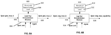
- FIG. 6A is a block diagram illustration of a lead Q module 600 constructed in accordance with the present invention.
- the lead Q module 600 includes a threshold upper/lower level module 602 and a lead var interpolation module 604.
- the threshold upper/lower level module 602 processes the upper/lower level voltage threshold 504, discussed in reference to FIG. 5 .
- the interpolation module 604 is configured to receive a conventionally determined Qvar_pos_max_0 prediction signal 606, Qvar_out, and Vgrid values as inputs. These input values are analyzed based upon the upper/lower level voltage threshold 504. A Qvar_pos_max_2 signal 608 is produced as an output from the lead var interpolation module 604.
- FIG. 6B is a block diagram illustration of a lag Q module 610 constructed in accordance with the present invention.
- the lag Q module 610 includes a threshold upper/lower level module 612 and a lag var interpolation module 614.
- the threshold upper/lower level module 612 processes the upper/lower level voltage threshold 512 above, discussed in reference to FIG. 5 .
- the lag var interpolation module 614 is configured to receive a conventionally determined Qvar_neg_max_0 prediction signal 616, Qvar_out, and Vgrid values as inputs. These input values are analyzed based upon the upper/lower level voltage threshold 504. A Qvar_neg_max_capability signal 618 is produced as an output from the lag var negative interpolation module 614.
- FIG. 7 is a more detailed block diagram illustration of the converter control module 200 depicted in FIG. 2 .
- the converter module 200 can be included within the grid-tied converter 106, the present invention is not so limited.
- the converter module 200 could be a standalone component, embedded within another module, or provided in a completely different configuration.
- the converter module 200 includes a lead reactive power capability prediction segment 700, including a legacy module 702.
- the legacy module 702 conventionally determines Qvar_pos_max_0 signal 606, noted above in the discussion of FIG. 6A .
- the Qvar_pos_max_0 signal 606 is used as a reference limiter to an inverter, or converter.
- the Qvar_pos_max_0 signal 606 is provided as an input to the lead Q module 600, where the Qvar_pos_max_2 capability signal 608 is produced as an output, also noted above.
- the Qvar_pos_max_2 capability signal 608 is updated in response to the dynamically determined Qvar_pos_max_1 signal 402 prediction value. This update occurs within a minimum (e.g., combiner) module 708 to find a minimum value.
- a Qvar_pos_max_capability signal 710 is produced as an output signal.
- the converter module 200 includes a lag reactive power capability prediction segment 712 and a legacy module 703.
- the legacy module 703 conventionally determines the Qvar_neg_max_0 signal 616, noted above in the discussion of FIG. 6B .
- the Qvar_neg_max_0 signal 616 is provided as an input to the lag Q module 610, where the Qvar_neg_max_capability signal 618 is produced as an output.
- the Qvar_pos_max_capability signal 710 and the Qvar_neg_max_capability signal 618 are representative of a dynamic Q capability prediction signal 720, provided as a real-time output signal from the converter control module 200.
- the dynamic Q capability prediction signal 720 is indicative of the real-time Q compensation volume of the embodiments of the present invention.
- the dynamic Q capability prediction signal 720 can be provided as a more accurate and comprehensive reference information to the grid management system.
- the grid management system can utilize this prediction information to leverage the converter's reactive power capability when regulating the grid voltage. This technique enhances the operational efficiency of the electricity power management system 100.
- FIG. 8 is a graphical illustration 800 depicting a comparison between a conventional Q capability prediction value waveform 802 and an actual maximum Q output waveform 804. That is, FIG. 8 depicts the actual problem of conventional reactive power capability prediction systems currently deployed in the field.
- the graphical illustration 800 is using a converter, or an inverter's, reactive power capability prediction value as set points sending back to the inverter to verify the function.
- grid voltage 806 rises as the inverter feeds lead reactive power into the grid.
- the conventional reactive power capability prediction value 802 and the actual maximum Q value 804 began to diverge. This divergence occurs because the DC-link voltage maximum limits, as discussed above, was not considered nor factored into the reactive power capability prediction value of these conventional approaches.
- the reactive power capability prediction value 802 and the actual capability value 804 should be very close. These values should not be diverging, as described above, and depicted in FIG. 8 .
- FIG. 9A is a graphical illustration 900 of a simulated lead (positive) Var prediction capability waveform 902 to an actual lead Var output waveform 904, as the grid voltage Vg 806 was hitting the upper limit defined in local grid code, in accordance with the present invention.
- the lead Var capability prediction waveform 902 is provided as a command to the converter, the lead Var prediction 902 and the actual lead Var output waveform 904 are virtually the same.
- FIG. 9B is a graphical illustration 906 of a simulated lag (negative) Var prediction capability waveform 908 to an actual lag Var output waveform 910, as the grid voltage Vg 806 was hitting the lower limit defined in local grid code, in accordance with the present invention.
- the lag Var capability prediction 908 and the actual lag Var output waveform 910 are virtually the same.
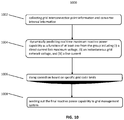
- FIG. 10 is a flowchart of an exemplary method 1000 of practicing an embodiment of the present invention.
- the method 1000 includes a step 1002 for collecting grid interconnection point information and converter internal information.
- a step 1004 includes dynamically predicting the real time maximum reactive power capability as a function of at least one from the group including (i) a direct current link maximum voltage, (ii) an instantaneous grid network voltage, and (iii) a line current.
- step 1006 doing correction based on specific grid code limits.
- step 1008 sending out the final reactive power capability information to grid management system.
Landscapes
- Engineering & Computer Science (AREA)
- Power Engineering (AREA)
- Health & Medical Sciences (AREA)
- Artificial Intelligence (AREA)
- Computer Vision & Pattern Recognition (AREA)
- Evolutionary Computation (AREA)
- Medical Informatics (AREA)
- Software Systems (AREA)
- Physics & Mathematics (AREA)
- General Physics & Mathematics (AREA)
- Automation & Control Theory (AREA)
- Supply And Distribution Of Alternating Current (AREA)
Claims (4)
- System (100) zum Regeln von Energie, wobei das System umfasst:ein Elektrizitätsnetz (102);eine Energiequelle (104);einen netzgekoppelten Leistungswandler (106), der mit dem Elektrizitätsnetz (102) und mit einem Gleichstromzwischenkreis verbunden ist, wobei der Leistungswandler (106) dazu konfiguriert ist, die Energie aus der Energiequelle (104) über den Gleichstromzwischenkreis zu empfangen, und dem Elektrizitätsnetz (102) Energie zuzuführen; undeine Steuerung (200);dadurch gekennzeichnet, dass die Steuerung (200) dazu konfiguriert ist, maximale Echtzeit-Blindleistungskapazität (700) des Leistungswandlers (106), die eine vorauseilende maximale Blindleistungskapazität (710) und eine nacheilende maximale Blindleistungskapazität (618) einschließt, dynamisch vorherzusagen;wobei die vorhergesagte maximale Blindleistungskapazität dafür konfiguriert ist, Regelung der Energie zu optimieren;wobei die Steuerung (200) umfasst:
ein Vorhersagemodul (400) für vorauseilende maximale Blindleistungskapazität, das ein erstes Signal (402) für vorauseilende maximale Blindleistung, Qvar_pos_max_1, gemäß den folgenden Gleichungen (Gleichung 1) bis (Gleichung 5) ableitet: Z die Leitungsimpedanz zwischen dem Leistungswandler (106) und dem Elektrizitätsnetz (102) ist,fg die Frequenz des Elektrizitätsnetzes (102) ist, undL die Induktivität des Leistungswandlers (106) ist,
 I_x ein Leitungsstrom entlang einer x-Achse für einen Vektor einer Wechselstromleitungsspannung Vc des Leistungswandlers (106) ist,Pout Einspeiseleistung des Leistungswandlers (106) ist, undVg die momentane Leitungsspannung des Elektrizitätsnetzes (102) ist;

Vc_max die maximal erreichbare Wechselstromleitungsspannung des Leistungswandlers (106) ist; ein Modul (600) für vorauseilende Blindleistung, das ein zweites Signal (608) für vorauseilende maximale Blindleistung aus einem dritten Signal (606) für vorauseilende maximale Blindleistung unter Bezugnahme auf obere und untere Schwellenspannungspegel, die mit Field Grid Codes assoziiert sind, den Blindleistungsausgang des Leistungswandlers (106) und die momentane Leitungsspannung des Elektrizitätsnetzes (102) ableitet; undein Modul (610) für nacheilende Blindleistung, das die nacheilende maximale Blindleistungskapazität (618) aus einem Signal (616) für nacheilende maximale Blindleistung unter Bezugnahme auf obere und untere Schwellenspannungspegel, die mit Field Grid Codes assoziiert sind, den Blindleistungsausgang des Leistungswandlers (106), und die momentane Leitungsspannung des Elektrizitätsnetzes (102) ableitet;wobei es sich bei der vorauseilenden maximalen Blindleistungskapazität (710) um das Minimum aus dem ersten Signal (402) für vorauseilende maximale Blindleistung, und dem zweiten Signal (608) für vorauseilende maximale Blindleistung handelt.
 - System nach Anspruch 1, wobei es sich bei der Energiequelle (104) um eine Solarenergiequelle und/oder eine Windenergiequelle handelt.
- System nach Anspruch 1, wobei die Vorhersage der maximalen Blindleistungskapazität von angeschlossener Netzimpedanz unabhängig ist.
- Verfahren zum Regeln von Energie, die einem Elektrizitätsnetz (102) aus einer Energiequelle (104) bereitgestellt wird, wobei das Verfahren umfasst:Empfangen der Energie aus der Energiequelle (104) über einen Gleichstromzwischenkreis in einem netzgekoppelten Leistungswandler (106);und dadurch gekennzeichnet, dass es weiter umfasst:dynamisches Vorhersagen der maximalen Echtzeit-Blindleistungskapazität des Leistungswandlers (106), die eine vorauseilende maximale Blindleistungskapazität (710) und eine nacheilende maximale Blindleistungskapazität (618) einschließt; undKonfigurieren der vorhergesagten maximalen Blindleistungskapazität, um Regelung der Energie zu optimieren;wobei der Schritt des dynamischen Vorhersagens der maximalen Echtzeit-Blindleistungskapazität einschließt:Ableiten, unter Verwendung eines Vorhersagemoduls (400) für vorauseilende maximale Blindleistungskapazität, eines ersten Signals (402) für vorauseilende maximale Blindleistung, Qvar_pos_max_1, gemäß den folgenden Gleichungen (Gleichung 1) bis (Gleichung 5):
 Z die Leitungsimpedanz zwischen dem Leistungswandler (106) und dem Elektrizitätsnetz (102) ist,fg die Frequenz des Elektrizitätsnetzes (102) ist, undL die Induktivität des Leistungswandlers (106) ist,
 I_x ein Leitungsstrom entlang einer x-Achse für einen Vektor einer Wechselstromleitungsspannung Vc des Leistungswandlers (106) ist,Pout Einspeiseleistung des Leistungswandlers (106) ist, undVg die momentane Leitungsspannung des Elektrizitätsnetzes (102) ist;

Vc_max die maximal erreichbare Wechselstromleitungsspannung des Leistungswandlers (106) ist; Ableiten, unter Verwendung eines Moduls (600) für vorauseilende Blindleistung, eines zweiten Signals (608) für vorauseilende maximale Blindleistung aus einem dritten Signal (606) für vorauseilende maximale Blindleistung unter Bezugnahme auf obere und untere Schwellenspannungspegel, die mit Field Grid Codes assoziiert sind, den Blindleistungsausgang des Leistungswandlers (106) und die momentane Leitungsspannung des Elektrizitätsnetzes (102); undAbleiten, unter Verwendung eines Moduls (610) für nacheilende Blindleistung, der nacheilenden maximalen Blindleistungskapazität (618) aus einem Signal (616) für nacheilende maximale Blindleistung unter Bezugnahme auf obere und untere Schwellenspannungspegel, die mit Field Grid Codes assoziiert sind, den Blindleistungsausgang des Leistungswandlers (106), und die momentane Leitungsspannung des Elektrizitätsnetzes (102);wobei es sich bei der vorauseilenden maximalen Blindleistungskapazität (710) um das Minimum aus dem ersten Signal (402) für vorauseilende maximale Blindleistung, und dem zweiten Signal (608) für vorauseilende maximale Blindleistung handelt.
Applications Claiming Priority (1)
| Application Number | Priority Date | Filing Date | Title |
|---|---|---|---|
| PCT/CN2014/078667 WO2015180074A1 (en) | 2014-05-28 | 2014-05-28 | Reactive power prediction capability |
Publications (3)
| Publication Number | Publication Date |
|---|---|
| EP3149825A1 EP3149825A1 (de) | 2017-04-05 |
| EP3149825A4 EP3149825A4 (de) | 2018-01-10 |
| EP3149825B1 true EP3149825B1 (de) | 2020-07-01 |
Family
ID=54697856
Family Applications (1)
| Application Number | Title | Priority Date | Filing Date |
|---|---|---|---|
| EP14893594.3A Active EP3149825B1 (de) | 2014-05-28 | 2014-05-28 | Reaktive leistungsvorhersagefähigkeit |
Country Status (4)
| Country | Link |
|---|---|
| US (1) | US10424928B2 (de) |
| EP (1) | EP3149825B1 (de) |
| CN (1) | CN106663943A (de) |
| WO (1) | WO2015180074A1 (de) |
Cited By (1)
| Publication number | Priority date | Publication date | Assignee | Title |
|---|---|---|---|---|
| EP4625748A4 (de) * | 2022-12-09 | 2026-04-01 | Huawei Digital Power Tech Co Ltd | Netzformungssteuerungsverfahren für einen stromwandler und stromwandler |
Families Citing this family (10)
| Publication number | Priority date | Publication date | Assignee | Title |
|---|---|---|---|---|
| KR101686296B1 (ko) * | 2014-09-04 | 2016-12-28 | 한국전력공사 | 전력 계통의 전압 안정도 관리 장치 및 그 방법 |
| US10447040B2 (en) * | 2014-10-15 | 2019-10-15 | Cummins Power Generation Ip, Inc. | Programmable inverter for controllable grid response |
| PT3378141T (pt) * | 2016-02-03 | 2019-12-05 | Siemens Ag | Capacidade de manutenção da alimentação em caso de falha para uma turbina eólica |
| US9857778B1 (en) | 2016-10-07 | 2018-01-02 | International Business Machines Corporation | Forecasting solar power generation using real-time power data, weather data, and complexity-based similarity factors |
| DE102016123011A1 (de) * | 2016-11-29 | 2018-05-30 | Innogy Se | Verfahren zum regeln von einem leistungswert eines offshore-windenergiesystems |
| US10819116B2 (en) | 2017-02-28 | 2020-10-27 | International Business Machines Corporation | Forecasting solar power generation using real-time power data |
| CN109742769B (zh) * | 2019-01-24 | 2022-12-30 | 国家电网有限公司 | 一种直流受端区域调相机无功置换方法和系统 |
| DE102019133566A1 (de) * | 2019-12-09 | 2021-06-10 | Rwe Renewables Gmbh | Verfahren sowie Stabilisierungsregler zum Betreiben eines Inselnetzes |
| CN115276091B (zh) * | 2022-08-10 | 2024-03-08 | 杭州东华电力设备有限公司 | 基于全纯函数嵌入电压灵敏度的分布式电源电压控制方法 |
| CN116073389B (zh) * | 2023-03-24 | 2023-07-11 | 国网湖北省电力有限公司经济技术研究院 | 基于受端电网无功同步平衡能力预测的电压稳定评估方法 |
Family Cites Families (24)
| Publication number | Priority date | Publication date | Assignee | Title |
|---|---|---|---|---|
| EP0187042B1 (de) * | 1984-12-28 | 1992-07-15 | Kabushiki Kaisha Toshiba | Einrichtung um parallel geschaltete Zyklokonverter zu betreiben |
| US5239251A (en) * | 1989-06-30 | 1993-08-24 | The State Of Oregon Acting By And Through The State Board Of Higher Education On Behalf Of Oregon State University | Brushless doubly-fed motor control system |
| US6492801B1 (en) * | 2001-08-21 | 2002-12-10 | Southern Company Services, Inc. | Method, apparatus, and system for real time reactive power output monitoring and predicting |
| US8239070B1 (en) * | 2003-06-27 | 2012-08-07 | Intellicon, Inc. | Root cause and system enhancement analysis |
| US7177728B2 (en) | 2003-12-30 | 2007-02-13 | Jay Warren Gardner | System and methods for maintaining power usage within a set allocation |
| US7687937B2 (en) * | 2005-03-18 | 2010-03-30 | Wisconsin Alumni Research Foundation | Control of small distributed energy resources |
| US8126685B2 (en) * | 2006-04-12 | 2012-02-28 | Edsa Micro Corporation | Automatic real-time optimization and intelligent control of electrical power distribution and transmission systems |
| US7844440B2 (en) * | 2006-07-07 | 2010-11-30 | Edsa Micro Corporation | Systems and methods for real-time dynamic simulation of uninterruptible power supply solutions and their control logic systems |
| KR100794245B1 (ko) * | 2006-08-22 | 2008-01-11 | 한국전기연구원 | 기기 모델 파라메타를 이용한 지능형 발전기 무효전력한계치 감시 시스템 및 방법 |
| CN101499664A (zh) | 2008-02-03 | 2009-08-05 | 北京能高自动化技术有限公司 | 风力发电机组并网变流器低电压穿越控制方法 |
| DE102008034532A1 (de) * | 2008-02-20 | 2009-08-27 | Repower Systems Ag | Windkraftanlage mit Umrichterregelung |
| ES2333393B1 (es) * | 2008-06-06 | 2011-01-07 | Accioona Windpower, S.A | Sistema y metodo de control de un aerogenerador. |
| US8406019B2 (en) * | 2008-09-15 | 2013-03-26 | General Electric Company | Reactive power compensation in solar power system |
| CN103503267A (zh) | 2011-05-10 | 2014-01-08 | Abb研究有限公司 | 一种控制器中控制动态补偿器的方法、控制器、计算机程序和计算机程序产品 |
| CN102255323A (zh) | 2011-07-22 | 2011-11-23 | 国电联合动力技术有限公司 | 一种双馈风力发电机组无功功率极限的计算方法 |
| CN102299527B (zh) * | 2011-08-23 | 2013-05-01 | 国电联合动力技术有限公司 | 一种风电场无功功率控制方法和系统 |
| JP5705076B2 (ja) | 2011-09-27 | 2015-04-22 | 三菱電機株式会社 | 分散電源用制御装置および集中型電圧制御システム |
| CN102354992B (zh) | 2011-09-30 | 2013-09-25 | 华北电力大学 | 风电场无功功率控制方法 |
| CN102361324B (zh) | 2011-10-17 | 2014-08-06 | 国电联合动力技术有限公司 | 双馈风电机组无功支撑的机端电压调节方法及其系统 |
| EP2629386B1 (de) * | 2012-02-16 | 2018-01-10 | GE Renewable Technologies | Verfahren zur verhinderung der spannungsinstabilität in einem elektrischen netz eines offshore-windparks |
| US9373958B2 (en) * | 2012-03-22 | 2016-06-21 | Sunpower Corporation | Control techniques for photovoltaic power plants |
| US9590423B2 (en) * | 2012-08-31 | 2017-03-07 | Abb Research Ltd. | Power distribution system loss reduction with distributed energy resource control |
| EP2757257B1 (de) * | 2013-01-22 | 2017-11-22 | GE Renewable Technologies | Verfahren und Vorrichtungen zum Regeln der Leistung von Generatoren |
| US9812870B2 (en) * | 2013-08-21 | 2017-11-07 | Nec Corporation | Microgrid reactive power management for voltage regulation during and subsequent to islanding |
-
2014
- 2014-05-28 CN CN201480079383.4A patent/CN106663943A/zh active Pending
- 2014-05-28 WO PCT/CN2014/078667 patent/WO2015180074A1/en not_active Ceased
- 2014-05-28 US US15/314,286 patent/US10424928B2/en active Active
- 2014-05-28 EP EP14893594.3A patent/EP3149825B1/de active Active
Non-Patent Citations (1)
| Title |
|---|
| None * |
Cited By (1)
| Publication number | Priority date | Publication date | Assignee | Title |
|---|---|---|---|---|
| EP4625748A4 (de) * | 2022-12-09 | 2026-04-01 | Huawei Digital Power Tech Co Ltd | Netzformungssteuerungsverfahren für einen stromwandler und stromwandler |
Also Published As
| Publication number | Publication date |
|---|---|
| WO2015180074A1 (en) | 2015-12-03 |
| EP3149825A1 (de) | 2017-04-05 |
| US10424928B2 (en) | 2019-09-24 |
| CN106663943A (zh) | 2017-05-10 |
| EP3149825A4 (de) | 2018-01-10 |
| US20170250534A1 (en) | 2017-08-31 |
Similar Documents
| Publication | Publication Date | Title |
|---|---|---|
| EP3149825B1 (de) | Reaktive leistungsvorhersagefähigkeit | |
| Yang et al. | Wide-scale adoption of photovoltaic energy: Grid code modifications are explored in the distribution grid | |
| KR101850663B1 (ko) | 전기 공급 그리드 내로의 전기 에너지의 공급 방법 및 그 장치 | |
| Nanou et al. | Modeling of a PV system with grid code compatibility | |
| Zhou et al. | Characteristic investigation and overvoltage suppression of MMC-HVDC integrated offshore wind farms under onshore valve-side SPG fault | |
| Nath et al. | Study of sub-synchronous control interaction due to the interconnection of wind farms to a series compensated transmission system | |
| Joseph et al. | Dynamic control of MVDC link embedded in distribution network:—Case study on ANGLE-DC | |
| Farantatos et al. | Short-circuit current contribution of converter interfaced wind turbines and the impact on system protection | |
| Ugalde-Loo et al. | Open access simulation toolbox for the grid connection of offshore wind farms using multi-terminal HVDC networks | |
| Liu et al. | Temporary overvoltage assessment and suppression in heterogeneous renewable energy power systems | |
| Wang et al. | A reduced-order robust wide-area damping control for wind-PV-thermal-bundled power system considering operational uncertainties and communication resilience | |
| Almesri et al. | Low Voltage Ride-Through Capability of Grid-Connected PV Systems: A Comparative Study of Grid-Following and Grid-Forming Converters Under Current Limits | |
| Kyesswa et al. | Dynamic Modeling of Wind and Solar Power Generation with Grid Support for Large-Scale Integration in Power Systems | |
| Rahman et al. | Modeling and design of a multiport magnetic bus-based novel wind-wave hybrid ocean energy technology | |
| Saha et al. | Modelling and control of STATCOM to ensure stable power system operation | |
| Hamida et al. | HVDC transmission in the interconnected south mediterranean region-LFC control analysis | |
| Sahoo et al. | Rethinking grid codes from protection perspective: A case study on negative sequence directional relay | |
| Wu et al. | Impact of a power converter virtual impedance based fast fault current injection control strategy on distance protection | |
| Bullich-Massagué et al. | Power Plant Control in Large Scale PV Plants. Design, implementation and validation in a 9.4 MW PV plant | |
| Bhalja et al. | Improvement of grid resiliency during high penetration of smart grid renewable resources using coordinated protection and control strategies | |
| Lopes et al. | Reactive power control of direct drive synchronous wind generators to enhance the low voltage ride-through capability | |
| Amarís | Power Quality Solutions for Voltage Dip compensation at wind farms | |
| Karkri et al. | A comparison between Series Dynamic Resistors and CROWBAR circuit protection for LVRT capability of Doubly-Fed Induction Generator | |
| Fogli et al. | Analysis of ac dispatchable microgrid during grid-connected and isolated modes transitions | |
| Trevisan | Contribution to Assessment Methods for Low-Frequency Interactions in Inverter Dominated Power Systems |
Legal Events
| Date | Code | Title | Description |
|---|---|---|---|
| STAA | Information on the status of an ep patent application or granted ep patent |
Free format text: STATUS: THE INTERNATIONAL PUBLICATION HAS BEEN MADE |
|
| PUAI | Public reference made under article 153(3) epc to a published international application that has entered the european phase |
Free format text: ORIGINAL CODE: 0009012 |
|
| STAA | Information on the status of an ep patent application or granted ep patent |
Free format text: STATUS: REQUEST FOR EXAMINATION WAS MADE |
|
| 17P | Request for examination filed |
Effective date: 20161125 |
|
| AK | Designated contracting states |
Kind code of ref document: A1 Designated state(s): AL AT BE BG CH CY CZ DE DK EE ES FI FR GB GR HR HU IE IS IT LI LT LU LV MC MK MT NL NO PL PT RO RS SE SI SK SM TR |
|
| AX | Request for extension of the european patent |
Extension state: BA ME |
|
| DAX | Request for extension of the european patent (deleted) | ||
| A4 | Supplementary search report drawn up and despatched |
Effective date: 20171213 |
|
| RIC1 | Information provided on ipc code assigned before grant |
Ipc: H02J 3/18 20060101AFI20171207BHEP Ipc: G05B 13/02 20060101ALN20171207BHEP Ipc: H02J 3/38 20060101ALI20171207BHEP |
|
| STAA | Information on the status of an ep patent application or granted ep patent |
Free format text: STATUS: EXAMINATION IS IN PROGRESS |
|
| 17Q | First examination report despatched |
Effective date: 20190715 |
|
| RIC1 | Information provided on ipc code assigned before grant |
Ipc: G05B 13/02 20060101ALN20191217BHEP Ipc: H02J 3/18 20060101AFI20191217BHEP Ipc: H02J 3/38 20060101ALI20191217BHEP |
|
| GRAP | Despatch of communication of intention to grant a patent |
Free format text: ORIGINAL CODE: EPIDOSNIGR1 |
|
| STAA | Information on the status of an ep patent application or granted ep patent |
Free format text: STATUS: GRANT OF PATENT IS INTENDED |
|
| INTG | Intention to grant announced |
Effective date: 20200127 |
|
| GRAS | Grant fee paid |
Free format text: ORIGINAL CODE: EPIDOSNIGR3 |
|
| GRAA | (expected) grant |
Free format text: ORIGINAL CODE: 0009210 |
|
| STAA | Information on the status of an ep patent application or granted ep patent |
Free format text: STATUS: THE PATENT HAS BEEN GRANTED |
|
| AK | Designated contracting states |
Kind code of ref document: B1 Designated state(s): AL AT BE BG CH CY CZ DE DK EE ES FI FR GB GR HR HU IE IS IT LI LT LU LV MC MK MT NL NO PL PT RO RS SE SI SK SM TR |
|
| REG | Reference to a national code |
Ref country code: CH Ref legal event code: EP Ref country code: AT Ref legal event code: REF Ref document number: 1287062 Country of ref document: AT Kind code of ref document: T Effective date: 20200715 |
|
| REG | Reference to a national code |
Ref country code: IE Ref legal event code: FG4D |
|
| REG | Reference to a national code |
Ref country code: DE Ref legal event code: R096 Ref document number: 602014067369 Country of ref document: DE |
|
| REG | Reference to a national code |
Ref country code: LT Ref legal event code: MG4D |
|
| PG25 | Lapsed in a contracting state [announced via postgrant information from national office to epo] |
Ref country code: BG Free format text: LAPSE BECAUSE OF FAILURE TO SUBMIT A TRANSLATION OF THE DESCRIPTION OR TO PAY THE FEE WITHIN THE PRESCRIBED TIME-LIMIT Effective date: 20201001 |
|
| REG | Reference to a national code |
Ref country code: NL Ref legal event code: MP Effective date: 20200701 |
|
| REG | Reference to a national code |
Ref country code: AT Ref legal event code: MK05 Ref document number: 1287062 Country of ref document: AT Kind code of ref document: T Effective date: 20200701 |
|
| PG25 | Lapsed in a contracting state [announced via postgrant information from national office to epo] |
Ref country code: CZ Free format text: LAPSE BECAUSE OF FAILURE TO SUBMIT A TRANSLATION OF THE DESCRIPTION OR TO PAY THE FEE WITHIN THE PRESCRIBED TIME-LIMIT Effective date: 20200701 Ref country code: ES Free format text: LAPSE BECAUSE OF FAILURE TO SUBMIT A TRANSLATION OF THE DESCRIPTION OR TO PAY THE FEE WITHIN THE PRESCRIBED TIME-LIMIT Effective date: 20200701 Ref country code: PT Free format text: LAPSE BECAUSE OF FAILURE TO SUBMIT A TRANSLATION OF THE DESCRIPTION OR TO PAY THE FEE WITHIN THE PRESCRIBED TIME-LIMIT Effective date: 20201102 Ref country code: AT Free format text: LAPSE BECAUSE OF FAILURE TO SUBMIT A TRANSLATION OF THE DESCRIPTION OR TO PAY THE FEE WITHIN THE PRESCRIBED TIME-LIMIT Effective date: 20200701 Ref country code: LT Free format text: LAPSE BECAUSE OF FAILURE TO SUBMIT A TRANSLATION OF THE DESCRIPTION OR TO PAY THE FEE WITHIN THE PRESCRIBED TIME-LIMIT Effective date: 20200701 Ref country code: HR Free format text: LAPSE BECAUSE OF FAILURE TO SUBMIT A TRANSLATION OF THE DESCRIPTION OR TO PAY THE FEE WITHIN THE PRESCRIBED TIME-LIMIT Effective date: 20200701 Ref country code: NO Free format text: LAPSE BECAUSE OF FAILURE TO SUBMIT A TRANSLATION OF THE DESCRIPTION OR TO PAY THE FEE WITHIN THE PRESCRIBED TIME-LIMIT Effective date: 20201001 Ref country code: FI Free format text: LAPSE BECAUSE OF FAILURE TO SUBMIT A TRANSLATION OF THE DESCRIPTION OR TO PAY THE FEE WITHIN THE PRESCRIBED TIME-LIMIT Effective date: 20200701 Ref country code: GR Free format text: LAPSE BECAUSE OF FAILURE TO SUBMIT A TRANSLATION OF THE DESCRIPTION OR TO PAY THE FEE WITHIN THE PRESCRIBED TIME-LIMIT Effective date: 20201002 Ref country code: SE Free format text: LAPSE BECAUSE OF FAILURE TO SUBMIT A TRANSLATION OF THE DESCRIPTION OR TO PAY THE FEE WITHIN THE PRESCRIBED TIME-LIMIT Effective date: 20200701 |
|
| PG25 | Lapsed in a contracting state [announced via postgrant information from national office to epo] |
Ref country code: RS Free format text: LAPSE BECAUSE OF FAILURE TO SUBMIT A TRANSLATION OF THE DESCRIPTION OR TO PAY THE FEE WITHIN THE PRESCRIBED TIME-LIMIT Effective date: 20200701 Ref country code: LV Free format text: LAPSE BECAUSE OF FAILURE TO SUBMIT A TRANSLATION OF THE DESCRIPTION OR TO PAY THE FEE WITHIN THE PRESCRIBED TIME-LIMIT Effective date: 20200701 Ref country code: PL Free format text: LAPSE BECAUSE OF FAILURE TO SUBMIT A TRANSLATION OF THE DESCRIPTION OR TO PAY THE FEE WITHIN THE PRESCRIBED TIME-LIMIT Effective date: 20200701 Ref country code: IS Free format text: LAPSE BECAUSE OF FAILURE TO SUBMIT A TRANSLATION OF THE DESCRIPTION OR TO PAY THE FEE WITHIN THE PRESCRIBED TIME-LIMIT Effective date: 20201101 |
|
| PG25 | Lapsed in a contracting state [announced via postgrant information from national office to epo] |
Ref country code: NL Free format text: LAPSE BECAUSE OF FAILURE TO SUBMIT A TRANSLATION OF THE DESCRIPTION OR TO PAY THE FEE WITHIN THE PRESCRIBED TIME-LIMIT Effective date: 20200701 |
|
| REG | Reference to a national code |
Ref country code: DE Ref legal event code: R097 Ref document number: 602014067369 Country of ref document: DE |
|
| PG25 | Lapsed in a contracting state [announced via postgrant information from national office to epo] |
Ref country code: IT Free format text: LAPSE BECAUSE OF FAILURE TO SUBMIT A TRANSLATION OF THE DESCRIPTION OR TO PAY THE FEE WITHIN THE PRESCRIBED TIME-LIMIT Effective date: 20200701 Ref country code: DK Free format text: LAPSE BECAUSE OF FAILURE TO SUBMIT A TRANSLATION OF THE DESCRIPTION OR TO PAY THE FEE WITHIN THE PRESCRIBED TIME-LIMIT Effective date: 20200701 Ref country code: EE Free format text: LAPSE BECAUSE OF FAILURE TO SUBMIT A TRANSLATION OF THE DESCRIPTION OR TO PAY THE FEE WITHIN THE PRESCRIBED TIME-LIMIT Effective date: 20200701 Ref country code: SM Free format text: LAPSE BECAUSE OF FAILURE TO SUBMIT A TRANSLATION OF THE DESCRIPTION OR TO PAY THE FEE WITHIN THE PRESCRIBED TIME-LIMIT Effective date: 20200701 Ref country code: RO Free format text: LAPSE BECAUSE OF FAILURE TO SUBMIT A TRANSLATION OF THE DESCRIPTION OR TO PAY THE FEE WITHIN THE PRESCRIBED TIME-LIMIT Effective date: 20200701 |
|
| PLBE | No opposition filed within time limit |
Free format text: ORIGINAL CODE: 0009261 |
|
| STAA | Information on the status of an ep patent application or granted ep patent |
Free format text: STATUS: NO OPPOSITION FILED WITHIN TIME LIMIT |
|
| PG25 | Lapsed in a contracting state [announced via postgrant information from national office to epo] |
Ref country code: AL Free format text: LAPSE BECAUSE OF FAILURE TO SUBMIT A TRANSLATION OF THE DESCRIPTION OR TO PAY THE FEE WITHIN THE PRESCRIBED TIME-LIMIT Effective date: 20200701 |
|
| 26N | No opposition filed |
Effective date: 20210406 |
|
| PG25 | Lapsed in a contracting state [announced via postgrant information from national office to epo] |
Ref country code: SK Free format text: LAPSE BECAUSE OF FAILURE TO SUBMIT A TRANSLATION OF THE DESCRIPTION OR TO PAY THE FEE WITHIN THE PRESCRIBED TIME-LIMIT Effective date: 20200701 |
|
| PG25 | Lapsed in a contracting state [announced via postgrant information from national office to epo] |
Ref country code: SI Free format text: LAPSE BECAUSE OF FAILURE TO SUBMIT A TRANSLATION OF THE DESCRIPTION OR TO PAY THE FEE WITHIN THE PRESCRIBED TIME-LIMIT Effective date: 20200701 |
|
| REG | Reference to a national code |
Ref country code: CH Ref legal event code: PL |
|
| PG25 | Lapsed in a contracting state [announced via postgrant information from national office to epo] |
Ref country code: LI Free format text: LAPSE BECAUSE OF NON-PAYMENT OF DUE FEES Effective date: 20210531 Ref country code: MC Free format text: LAPSE BECAUSE OF FAILURE TO SUBMIT A TRANSLATION OF THE DESCRIPTION OR TO PAY THE FEE WITHIN THE PRESCRIBED TIME-LIMIT Effective date: 20200701 Ref country code: LU Free format text: LAPSE BECAUSE OF NON-PAYMENT OF DUE FEES Effective date: 20210528 Ref country code: CH Free format text: LAPSE BECAUSE OF NON-PAYMENT OF DUE FEES Effective date: 20210531 |
|
| REG | Reference to a national code |
Ref country code: BE Ref legal event code: MM Effective date: 20210531 |
|
| PG25 | Lapsed in a contracting state [announced via postgrant information from national office to epo] |
Ref country code: IE Free format text: LAPSE BECAUSE OF NON-PAYMENT OF DUE FEES Effective date: 20210528 |
|
| PG25 | Lapsed in a contracting state [announced via postgrant information from national office to epo] |
Ref country code: BE Free format text: LAPSE BECAUSE OF NON-PAYMENT OF DUE FEES Effective date: 20210531 |
|
| PG25 | Lapsed in a contracting state [announced via postgrant information from national office to epo] |
Ref country code: HU Free format text: LAPSE BECAUSE OF FAILURE TO SUBMIT A TRANSLATION OF THE DESCRIPTION OR TO PAY THE FEE WITHIN THE PRESCRIBED TIME-LIMIT; INVALID AB INITIO Effective date: 20140528 |
|
| PG25 | Lapsed in a contracting state [announced via postgrant information from national office to epo] |
Ref country code: CY Free format text: LAPSE BECAUSE OF FAILURE TO SUBMIT A TRANSLATION OF THE DESCRIPTION OR TO PAY THE FEE WITHIN THE PRESCRIBED TIME-LIMIT Effective date: 20200701 |
|
| PG25 | Lapsed in a contracting state [announced via postgrant information from national office to epo] |
Ref country code: MK Free format text: LAPSE BECAUSE OF FAILURE TO SUBMIT A TRANSLATION OF THE DESCRIPTION OR TO PAY THE FEE WITHIN THE PRESCRIBED TIME-LIMIT Effective date: 20200701 |
|
| PG25 | Lapsed in a contracting state [announced via postgrant information from national office to epo] |
Ref country code: MT Free format text: LAPSE BECAUSE OF FAILURE TO SUBMIT A TRANSLATION OF THE DESCRIPTION OR TO PAY THE FEE WITHIN THE PRESCRIBED TIME-LIMIT Effective date: 20200701 |
|
| PGFP | Annual fee paid to national office [announced via postgrant information from national office to epo] |
Ref country code: DE Payment date: 20250423 Year of fee payment: 12 |
|
| PGFP | Annual fee paid to national office [announced via postgrant information from national office to epo] |
Ref country code: GB Payment date: 20250423 Year of fee payment: 12 |
|
| PGFP | Annual fee paid to national office [announced via postgrant information from national office to epo] |
Ref country code: FR Payment date: 20250423 Year of fee payment: 12 |
|
| PG25 | Lapsed in a contracting state [announced via postgrant information from national office to epo] |
Ref country code: TR Free format text: LAPSE BECAUSE OF FAILURE TO SUBMIT A TRANSLATION OF THE DESCRIPTION OR TO PAY THE FEE WITHIN THE PRESCRIBED TIME-LIMIT Effective date: 20200701 |