EP3149834B1 - Alimentation électrique avec transition entre l'opération et mode éco dépendante de courant de sortie - Google Patents
Alimentation électrique avec transition entre l'opération et mode éco dépendante de courant de sortie Download PDFInfo
- Publication number
- EP3149834B1 EP3149834B1 EP15713308.3A EP15713308A EP3149834B1 EP 3149834 B1 EP3149834 B1 EP 3149834B1 EP 15713308 A EP15713308 A EP 15713308A EP 3149834 B1 EP3149834 B1 EP 3149834B1
- Authority
- EP
- European Patent Office
- Prior art keywords
- supply device
- power supply
- current
- operating state
- amplitude
- Prior art date
- Legal status (The legal status is an assumption and is not a legal conclusion. Google has not performed a legal analysis and makes no representation as to the accuracy of the status listed.)
- Not-in-force
Links
Images



Classifications
-
- H—ELECTRICITY
- H02—GENERATION; CONVERSION OR DISTRIBUTION OF ELECTRIC POWER
- H02J—ELECTRIC POWER NETWORKS; CIRCUIT ARRANGEMENTS OR SYSTEMS FOR SUPPLYING OR DISTRIBUTING ELECTRIC POWER; SYSTEMS FOR STORING ELECTRIC ENERGY
- H02J9/00—Circuit arrangements for emergency or stand-by power supply, e.g. for emergency lighting
- H02J9/005—Circuit arrangements for emergency or stand-by power supply, e.g. for emergency lighting using a power saving mode
-
- H—ELECTRICITY
- H02—GENERATION; CONVERSION OR DISTRIBUTION OF ELECTRIC POWER
- H02J—ELECTRIC POWER NETWORKS; CIRCUIT ARRANGEMENTS OR SYSTEMS FOR SUPPLYING OR DISTRIBUTING ELECTRIC POWER; SYSTEMS FOR STORING ELECTRIC ENERGY
- H02J9/00—Circuit arrangements for emergency or stand-by power supply, e.g. for emergency lighting
- H02J9/005—Circuit arrangements for emergency or stand-by power supply, e.g. for emergency lighting using a power saving mode
- H02J9/007—Detection of the absence of a load
-
- H—ELECTRICITY
- H02—GENERATION; CONVERSION OR DISTRIBUTION OF ELECTRIC POWER
- H02M—APPARATUS FOR CONVERSION BETWEEN AC AND AC, BETWEEN AC AND DC, OR BETWEEN DC AND DC, AND FOR USE WITH MAINS OR SIMILAR POWER SUPPLY SYSTEMS; CONVERSION OF DC OR AC INPUT POWER INTO SURGE OUTPUT POWER; CONTROL OR REGULATION THEREOF
- H02M1/00—Details of apparatus for conversion
- H02M1/0003—Details of control, feedback or regulation circuits
- H02M1/0032—Control circuits allowing low power mode operation, e.g. in standby mode
-
- Y—GENERAL TAGGING OF NEW TECHNOLOGICAL DEVELOPMENTS; GENERAL TAGGING OF CROSS-SECTIONAL TECHNOLOGIES SPANNING OVER SEVERAL SECTIONS OF THE IPC; TECHNICAL SUBJECTS COVERED BY FORMER USPC CROSS-REFERENCE ART COLLECTIONS [XRACs] AND DIGESTS
- Y02—TECHNOLOGIES OR APPLICATIONS FOR MITIGATION OR ADAPTATION AGAINST CLIMATE CHANGE
- Y02B—CLIMATE CHANGE MITIGATION TECHNOLOGIES RELATED TO BUILDINGS, e.g. HOUSING, HOUSE APPLIANCES OR RELATED END-USER APPLICATIONS
- Y02B70/00—Technologies for an efficient end-user side electric power management and consumption
- Y02B70/10—Technologies improving the efficiency by using switched-mode power supplies [SMPS], i.e. efficient power electronics conversion e.g. power factor correction or reduction of losses in power supplies or efficient standby modes
-
- Y—GENERAL TAGGING OF NEW TECHNOLOGICAL DEVELOPMENTS; GENERAL TAGGING OF CROSS-SECTIONAL TECHNOLOGIES SPANNING OVER SEVERAL SECTIONS OF THE IPC; TECHNICAL SUBJECTS COVERED BY FORMER USPC CROSS-REFERENCE ART COLLECTIONS [XRACs] AND DIGESTS
- Y02—TECHNOLOGIES OR APPLICATIONS FOR MITIGATION OR ADAPTATION AGAINST CLIMATE CHANGE
- Y02B—CLIMATE CHANGE MITIGATION TECHNOLOGIES RELATED TO BUILDINGS, e.g. HOUSING, HOUSE APPLIANCES OR RELATED END-USER APPLICATIONS
- Y02B70/00—Technologies for an efficient end-user side electric power management and consumption
- Y02B70/30—Systems integrating technologies related to power network operation and communication or information technologies for improving the carbon footprint of the management of residential or tertiary loads, i.e. smart grids as climate change mitigation technology in the buildings sector, including also the last stages of power distribution and the control, monitoring or operating management systems at local level
-
- Y—GENERAL TAGGING OF NEW TECHNOLOGICAL DEVELOPMENTS; GENERAL TAGGING OF CROSS-SECTIONAL TECHNOLOGIES SPANNING OVER SEVERAL SECTIONS OF THE IPC; TECHNICAL SUBJECTS COVERED BY FORMER USPC CROSS-REFERENCE ART COLLECTIONS [XRACs] AND DIGESTS
- Y04—INFORMATION OR COMMUNICATION TECHNOLOGIES HAVING AN IMPACT ON OTHER TECHNOLOGY AREAS
- Y04S—SYSTEMS INTEGRATING TECHNOLOGIES RELATED TO POWER NETWORK OPERATION, COMMUNICATION OR INFORMATION TECHNOLOGIES FOR IMPROVING THE ELECTRICAL POWER GENERATION, TRANSMISSION, DISTRIBUTION, MANAGEMENT OR USAGE, i.e. SMART GRIDS
- Y04S20/00—Management or operation of end-user stationary applications or the last stages of power distribution; Controlling, monitoring or operating thereof
- Y04S20/20—End-user application control systems
Definitions
- the present invention relates to an energy supply device, in particular a power supply unit.
- An energy supply device such as a power supply unit, is a stand-alone device or an assembly for the energy supply of devices or assemblies that require different voltages and currents than are provided by the energy supply network.
- an electrical power supply device operates independently of the load connected to the power supply device.
- the energy supply device When changing to the standby mode of a load connected to the energy supply device, the energy supply device usually continues to provide the input voltage applied to the energy supply device for the connected load. If the energy supply of the energy supply device with a connected load is switched off, a switching unit, for example a contactor, is usually connected upstream in order to counteract an increased voltage build-up on the electrically connected energy supply device and the load during the switching off of the energy supply.
- a switching unit for example a contactor
- auxiliary energy is usually required in order to convert the energy supply device from its standby state to the active state.
- Some power supply devices therefore have a digital input in order to switch the power supply device on or off at a fixed level. This requires a control input that is controlled by a controller.
- the publication DE 196 00 962 A1 discloses a switching power supply with a stand-by operation. To switch from stand-by mode to normal mode, the signal is switched off at a connection for opening a switch, so that the output voltages are regulated again via a Zener diode.
- the publication US 6 320 766 B1 relates to an energy saving circuit of an AC / DC adapter for a portable computer.
- the publication US 2004/066662 A1 relates to a voltage supply device with a load detector which detects whether an external device or load is connected to the output terminals of the voltage supply device.
- the publication US 7 064 531 B1 relates to a voltage regulator with MOS transistors.
- the publication US 2003/067287 A1 relates to a supply voltage circuit in which a supply voltage is generated by a DC / DC converter from a mains voltage.
- the publication US 2009/108822 A1 relates to a voltage supply circuit that automatically switches its operation mode between a light load mode and a heavy load mode, depending on a level of its output current.
- the publication DE 11 2011 105 015 T5 relates to an energy supply which switches between different operating modes and the associated different output voltages depending on the output current thresholds.
- the present invention is based on the finding that the energy supply device can be switched over between a first and a second operating state by detecting the current amplitude at the output of the energy supply device independently and efficiently.
- the object is achieved by an energy supply device for providing an output voltage and an output current, the energy supply device having a first operating state and a second operating state.
- the energy supply device has a measuring arrangement for detecting a current amplitude of the output current of the energy supply device and a signal generator for generating the output voltage and the output current.
- the signal generator is designed to reduce a voltage amplitude of the output voltage of the energy supply device in the first operating state of the energy supply device in order to change over to the second operating state if the detected current amplitude falls below a first current threshold value.
- the signal generator is also designed to increase a voltage amplitude of the output voltage of the energy supply device in the second operating state of the energy supply device in order to change over to the first operating state if the detected current amplitude exceeds a second current threshold value.
- the output power and thus the output voltage and the output current are higher in amount in the first operating state than in the second operating state.
- the transition of the energy supply device from the first operating state to the second operating state brings about a reduction in the output voltage of the energy supply device by, for example, 30% to 80% or, for example, by 50%.
- the signal generator reduces the voltage amplitude of the output voltage of the energy supply device from 24 V to 10-12 V in order to change from the first to the second operating state.
- the signal generator reduces the output current of the energy supply device by 5-20% or more below the nominal current in order to change from the first to the second operating state.
- the measuring arrangement repeatedly records the current amplitude of the output current at time intervals.
- the signal generator compares the detected current amplitude with the first and second current threshold values, which can be stored or stored in a memory of the signal generator.
- the energy supply device is, for example, a power supply unit.
- the advantage of the energy supply device according to the invention is that a transition between the first and the second operating state of the energy supply device takes place automatically.
- the first operating state is an active state and the second operating state is an energy-saving state, in particular a stand-by mode or a sleep mode.
- the output voltage and the output current are each set to a value which permits the operation of the electrical device connected to the energy supply device, while in the energy-saving state the output voltage and the output current are each set to a value that operation of the electrical device connected to the energy supply device Device.
- the second current threshold value is the first current threshold value or a further current threshold value.
- the first current threshold value is converted, for example, 5% -20% or more below the amplitude of the output current in the first operating state.
- the energy supply device changes from its second operating state to the first operating state if the first current threshold value is exceeded again, for example.
- the energy supply device does not transition from its second operating state into the first operating state until the second current threshold value has been reached or exceeded.
- the energy supply device already changes from the second operating state to the first operating state if the second current threshold value is reached or exceeded.
- the second current threshold value is lower than the first current threshold value in order to enable a transition of the energy supply device from its second operating state to the first operating state also for an electrical load connected to the energy supply device, the load current and load voltage of which are below a minimum load current and below a minimum load voltage.
- the advantage of the second current threshold value is that when the second current threshold value is exceeded by the load current of a load connected to the energy supply device, the energy supply device automatically changes from the second operating state to the first operating state without the use of an additional energy source.
- the first current threshold value or the second current threshold value or the further current threshold value can be set or pre-stored.
- the first current threshold value and the second current threshold value can be set or pre-stored current threshold values can be used to convert the energy supply device from its first operating state to its second operating state and vice versa.
- the energy supply device can be used flexibly, in particular for consumers with different load currents and load voltages, and does not lose the automatic transition from the first operating state to the second operating state and vice versa.
- the signal generator is designed, the detected current amplitude with the first current threshold value or to compare the second current threshold value or the further current threshold value.
- the signal generator repeatedly compares the detected current amplitude with the current threshold values at predetermined times.
- the predetermined points in time are preferably given at points in time after the end of equidistant time intervals which are, for example, in the range of seconds. For example, after 30, 20, 10 or 5 seconds have elapsed, the current amplitude is detected by the measuring arrangement and then compared by the signal generator with the first current threshold value or the second current threshold value or the further current threshold value.
- the signal generator is designed to reduce the voltage amplitude of the output voltage of the energy supply device to an adjustable first or pre-stored first voltage amplitude value if the detected current amplitude falls below the first current threshold value.
- the first threshold current value is preferably stored or can be stored in a memory of the signal generator.
- the signal generator is designed to reduce the voltage amplitude of the output voltage of the energy supply device in the first operating state after an adjustable or pre-stored first delay time interval has elapsed. After a first detection of a current amplitude below the first current threshold value, the measuring arrangement carries out a further detection of the current amplitude after the first delay time interval has elapsed. If the further detected current amplitude is also below the first current threshold value, the signal generator reduces the voltage amplitude of the output voltage of the energy supply device.
- the first includes
- Delay interval a period of several seconds, for example 30, 20, 10, 5 or 3 seconds.
- the signal generator is designed to increase the voltage amplitude of the output voltage of the energy supply device to an adjustable second or pre-stored second voltage amplitude value if the detected current amplitude exceeds the second current threshold value. If the measuring arrangement detects a detected current amplitude that exceeds the second current threshold value during operation of the energy supply device in the second operating state, the signal generator increases the voltage amplitude of the output voltage of the energy supply device to an adjustable second or pre-stored second voltage amplitude value.
- the voltage amplitude is reduced from a value in the range from 8 V to 14 V or from 10 V to 12 V in the second operating state to a voltage amplitude with a value between 20 V and 60 V or between 20 V and 28 V, or for example to 24 V im first operating state increased.
- the signal generator is designed to increase the voltage amplitude of the output voltage of the energy supply device after a pre-stored second delay time interval has elapsed after the detection of the exceeding of the second current threshold value of the current amplitude.
- the pre-stored second delay time interval comprises, for example, the same time period as the first delay time interval.
- the second delay interval comprises a time span of several seconds, for example 30, 20, 10, 5 or 3 seconds. It is also conceivable, for example, that the second delay time interval comprises a shorter time period than the first delay time interval, for example of 20, 10, 5, 3 or 1 second.
- the measuring arrangement has a measuring resistance.
- the measuring resistor is designed to detect the current amplitude of the output current on the basis of a voltage drop across the measuring resistor.
- the measuring resistor is provided in the form of a measuring shunt.
- a measuring shunt is a low-resistance electrical resistor that is used to measure the electrical current. The current flowing through a measuring shunt causes a voltage drop proportional to it, which is measured.
- the measuring shunt resistor is connected in parallel to a measuring circuit and then its voltage drop is recorded.
- measuring shunt resistors Since you cannot measure higher currents directly, you pass them through a measuring shunt resistor and measure the resulting voltage drop. Accordingly, the resistance value of measuring shunt resistors in the milli-ohm range or below is a few tenths or hundredths of a milli-ohm.
- the signal generator has a transformer with a primary side to which an input voltage can be applied and a secondary side for outputting the output voltage.
- the transformer of the signal generator has a primary winding, which is fed directly with the AC voltage of the energy supply network and the network frequency of the energy supply network.
- the transformer of the signal generator converts the input voltage, ie the AC voltage of the energy supply network, to the required output voltage value (s) and ensures electrical isolation.
- the secondary AC voltage on the secondary side of the transformer can be converted by means of a rectifier and a smoothing capacitor into an output DC voltage, which can then be provided at the output of the signal generator.
- a subsequent linear regulator and a buffer capacitor ensure a constant output voltage.
- the object is achieved by a method for operating an energy supply device, the energy supply device having a first operating state and a second operating state, a measuring arrangement for detecting a current amplitude of an output current of the energy supply device and a signal generator for controlling a voltage amplitude of the output voltage of the energy supply device having.
- the method comprises detecting a current amplitude of the output current of the energy supply device by means of the measuring arrangement; a reduction in a voltage amplitude of the output voltage of the energy supply device in the first operating state of the energy supply device by means of the signal generator in order to transition to the second operating state if the detected current amplitude falls below a first current threshold value.
- the method comprises increasing the voltage amplitude of the output voltage of the energy supply device in the second operating state of the energy supply device by means of the signal generator in order to change over to the first operating state if the detected current amplitude exceeds a second current threshold value.
- the amount of the output power and thus the output voltage and the output current are set to a higher value in the first operating state than in the second operating state.
- the output voltage of the energy supply device is reduced, for example, by 30% to 80% or, for example, by 50%.
- the voltage amplitude of the output voltage of the Power supply device reduced from 24 V to 10-12 V in order to change from the first operating state to the second operating state.
- the output current of the energy supply device is reduced by 5-20% or more below the nominal current, so that the energy supply device changes from the first operating state to the second operating state.
- the current arrangement of the output current is repeatedly recorded by the measuring arrangement at time intervals.
- the detected current amplitude is compared by the signal generator with the first current threshold and the second current threshold.
- the second current threshold value is, for example, set or pre-stored equal to the second current threshold value. For example, a lower or higher current threshold value can also be set or pre-stored for the second current threshold value.
- the energy supply device In the case of a lower second current threshold value, a consumer connected to the energy supply device and having a load with low load current and low load voltage can be recognized by the energy supply device. According to the method according to the invention, the energy supply device then automatically changes from the second operating state to the first operating state.
- the energy supply device is, for example, a power supply unit.
- the first operating state in the method according to the invention is set as an active state and the second operating state as an energy-saving state, in particular a stand-by mode or a sleep mode.
- the output voltage and the output current are each set to a value which permits the operation of the electrical device connected to the energy supply device, while in the energy-saving state, the output voltage and the output current are each set to a value that operation of the electrical device connected to the energy supply device Device.
- the advantage of the method according to the invention is that a transition between the first and the second operating state of the energy supply device takes place automatically.
- the detected current amplitude is compared by the signal generator with the first current threshold value or the second current threshold value or the further current threshold value.
- the signal generator compares the detected current amplitude with the current threshold values.
- the predetermined points in time are determined by the running of equidistant time intervals, which are, for example, in the range of seconds.
- the current amplitude is detected by the measuring arrangement and then compared by the signal generator with the first current threshold value or the second current threshold value or the further current threshold value.
- the first current threshold value or the second current threshold value or the further current threshold value are set or pre-stored.
- the signal generator reduces the voltage amplitude of the output voltage of the energy supply device to an adjustable first or pre-stored first voltage amplitude value if the detected current amplitude falls below the first current threshold value.
- the first threshold current value is stored in a memory of the signal generator.
- the output current of the energy supply device is simultaneously reduced, so that the energy supply device automatically, i.e., from its first operating state to the second operating state. without an additional energy source.
- the signal generator reduces the voltage amplitude of the output voltage of the energy supply device in the first operating state after an adjustable or pre-stored first delay time interval has elapsed. After a first detection of a current amplitude below the first current threshold value, a further current amplitude is detected by the measuring arrangement after the first delay time interval has elapsed. If the further detected current amplitude is also below the first current threshold value, the signal generator reduces the voltage amplitude of the output voltage of the energy supply device.
- the first delay interval comprises a time span of several seconds, for example 30, 20, 10, 5 or 3 seconds.
- the signal generator increases the voltage amplitude of the output voltage of the energy supply device to an adjustable second or pre-stored second voltage amplitude value if the detected current amplitude exceeds the current threshold value or the further current threshold value. If the measuring arrangement detects a detected current amplitude that exceeds the second current threshold value during operation of the energy supply device in the second operating state, the voltage generator increases the voltage amplitude of the output voltage of the energy supply device to an adjustable second or pre-stored second voltage amplitude value.
- the voltage amplitude is reduced from a value in the range from 8 V to 14 V or, for example, from 10 V to 12 V in the second operating state to a voltage amplitude with a value between 20 V and 60 V, or for example between 20 V and 28 V, or for example increased to 24 V in the first operating state.
- the voltage generator of the output voltage of the energy supply device is increased by the signal generator after a pre-stored second delay time interval has elapsed after the detection of the exceeding of the second current threshold value of the current amplitude.
- the pre-stored second delay time interval comprises, for example, the same time period as the first delay time interval.
- the second delay interval comprises a time span of several seconds, for example 30, 20, 10, 5 or 3 seconds.
- the second delay time interval comprises a shorter time period than the first delay time interval, for example of 20, 10, 5, 3 or 1 second.
- the advantage of the method according to the invention is that a transition from the second operating state to the first operating state cannot be initiated by random output current fluctuations.
- the object is achieved by a method for operating an energy supply device, the energy supply device having a first operating state and a second operating state.
- a current amplitude of the output current of the energy supply device is recorded.
- a voltage amplitude of the output voltage of the energy supply device in the first operating state of the energy supply device is reduced by means of a signal generator in order to change over to the second operating state if the detected current amplitude falls below a first current threshold value; and the voltage amplitude of the output voltage of the energy supply device in the second operating state of the energy supply device is increased by means of the signal generator in order to change over to the first operating state if the detected current amplitude exceeds a second current threshold value.
- the amount of the output power and thus the output voltage and the output current are set to a higher value in the first operating state than in the second operating state.
- the output voltage of the energy supply device is reduced, for example, in each case by 30% to 80% or, for example, by 50%.
- the voltage amplitude of the output voltage of the energy supply device is reduced from 24 V to 10-12 V in order to change from the first operating state to the second operating state.
- the output current of the energy supply device is reduced, for example, by 5-20% or more below the nominal current in order to change from the first operating state to the second operating state.
- the current amplitude of the output current is recorded repeatedly at time intervals.
- the detected current amplitude is compared with the first current threshold and the second current threshold.
- the second current threshold value is, for example, set or pre-stored equal to the second current threshold value. For example, a lower or higher current threshold value can also be set or pre-stored for the second current threshold value.
- the energy supply device automatically changes from the second operating state to the first operating state.
- the first operating state in the method according to the invention is set as an active state and the second operating state as an energy-saving state, in particular a stand-by mode or a sleep mode.
- the output voltage and the output current are each set to a value which allows the operation of an electrical device connected to the energy supply device, while in the energy-saving state, the output voltage and the output current are each set to a value which is an operation of the electrical device connected to the energy supply device Restrict the device.
- Fig. 1 shows a schematic representation of an energy supply device 100 with a measuring arrangement 101 for detecting a current amplitude of the output current of the energy supply device 100 and a signal generator 103 for generating the output voltage and the output current of the energy supply device 100.
- the measuring arrangement 101 is shown in FIG Fig. 2 shown schematically.
- the measuring arrangement 101 has a measuring resistor 201 and repeatedly detects the current amplitude of the output current of the energy supply device 100 at time intervals (see Fig. 1 ).
- the measuring arrangement 101 detects the current amplitude of the output current on the basis of a voltage drop U A -U M at the measuring resistor 201, where U A denotes the output voltage at the output of the measuring arrangement and U M the voltage across the measuring resistor 201.
- the measuring resistor 201 is in the form of a measuring shunt, as in Fig. 2 shown, given.
- the current flowing through a measuring resistor 201 causes a voltage drop U A -U M which is proportional to it and is measured.
- the measuring resistor 201 is connected in parallel to a measuring circuit 203, the voltage drop across the measuring resistor 201 being used for measurements of the current amplitude.
- the resistance value of the measuring resistor 201 is, for example, in the milli-ohm range or below a few tenths or hundredth milli-ohms.
- the signal generator 103 is electrically connected to the measuring arrangement 101 (see Fig. 1 ).
- Fig. 3 shows a schematic representation of the signal generator 103, which comprises a transformer 300.
- the transformer 300 has a primary side 301 on which a is supplied with an input voltage U, and a secondary side 303, which then provides a nominal output voltage U nom.
- the transformer of the signal generator has its primary side 301 on a primary winding 305, directly with the input voltage U a, the AC voltage of the power supply network and the network frequency that is the power supply mains, is fed and on its secondary side 303, a secondary winding 307 which provides the output voltage U nom .
- the transformer 300 of the signal generator 103 sets the input voltage U, that is, the AC voltage of the power supply network, or on the required output voltage values U nom by and provides DC isolation safely.
- the secondary AC voltage on the secondary side 303 of the transformer 300 can by means of a rectifier and a smoothing capacitor (not in Fig. 3 shown) are converted into a DC output voltage, which can be provided at the output of the signal generator 103.
- a subsequent linear regulator and a buffer capacitor (not in Fig. 3 shown) a constant output voltage U nom ready.
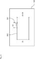
- Fig. 4 shows a schematic representation of the energy supply device 100, to the output 405 of which a consumer 401 is connected.
- a capacitor 403 is connected in parallel with the consumer 401.
- the capacitor 403 provides a supporting capacitance which provides a predetermined minimum power with a minimum load current and a minimum load voltage.
- the connected consumer 401 can be an electrical device, a motor, a PLC consumer (programmable logic controller), an industrial system, a DIN rail-mountable device, a control cabinet or another electrical consumer.
- the connected consumer can be operated with direct voltage or with alternating voltage.
- Fig. 5 shows a schematic diagram of the sequence of the method 500 for operating an energy supply device 100.
- the method 500 for operating the energy supply device 100 first comprises detecting 501 a current amplitude of the output current 601 of the energy supply device 100 by means of the measuring arrangement 101.
- the detected current amplitude of the output current 601 is then included adjustable or pre-stored current threshold values compared. After the comparison 503 with a first current threshold value I1 and a second current threshold value I2, depending on the result of the comparison 503, either a reduction 505 of the output voltage 603 or an increase 507 of the output voltage 603 takes place.
- the energy supply device 100 If the energy supply device 100 is in its first operating state 605, its active state, in which the consumer (s) 401 connected to the energy supply device 100 is supplied with energy, the energy supply device 100 goes on detecting 501 a current threshold value which is below a first current threshold value I1. from its first operating state 605 to its second operating state 607. This transition takes place by reducing 505 the voltage amplitude of the output voltage 603 of the energy supply device 100 to an adjustable or pre-stored output voltage value U low .
- the second operating state 607 is an energy-saving state, which is operated with the reduced output voltage U low .
- the energy supply device 100 changes from its second operating state 607 to its first operating state 605 upon detection 501 of a current threshold value which is above a second current threshold value I2. This transition occurs by increasing 507 the voltage amplitude of the output voltage 603 of the Power supply device 100 to an adjustable or pre-stored output voltage value U nom .
- the first operating state 605 is the active state, which is operated with the nominal output voltage U nom .
- Fig. 6 shows a schematic representation of the output voltage and the output current of the energy supply device.
- the energy supply device 100 In its first operating state 605, the energy supply device 100 provides an output voltage value U nom and an output current value I nom at its output or is increased to these values, so that connected loads 401 can be supplied with energy.
- the time course of the amplitude of the output current 601 and of the amplitude of the output voltage 603 are both in the first operating state 605 and in the second operating state 607 Fig. 6 shown.
- a consumer 401 connected to the energy supply device 100 is switched off, so that the amplitude of the output current 601 is reduced to a first current threshold value I1 or to a value below it at a time t 1 , while the amplitude of the output voltage 603 is reduced to Output voltage value U nom has remained constant.
- the energy supply device 100 switch from its first operating state 605 to the second operating state 607.
- the amplitude of the output voltage is reduced to the output voltage value U low and the amplitude of the output current is reduced to the second current threshold value I2.
- the amplitude of the output voltage is reduced from 24 V to 8V to 16V, or for example to 10-12 V, while the amplitude of the output current is reduced by 5-20% below the amplitude of the nominal current.
- the remaining output current I2 is measured repeatedly in equidistant time intervals in the second operating state 607. As long as the amplitude of the output current does not exceed the second current threshold value I2, the energy supply device 100 remains in its second operating state 607. Only when a consumer 401 with a load is connected or connected to the energy supply device 100 at a time t 3 does the amplitude of the output current 601 increased by the consumer 401 up to a time t 4 , while the amplitude of the output voltage 603 is kept constant at the output voltage value U low .
- the connection of the consumer 401 with a support capacitance can also result in a current peak in the amplitude of the output current 601 (not shown).
- the increase in the amplitude of the output current is evaluated as the end of the second operating state 607.
- the time t 4 that is to say after a second delay interval 611 has elapsed, which comprises the time period t 4 -t 3 , the amplitude of the output current 601 to the output current I nom and the amplitude of the output voltage to the nominal output voltage U nom 603 to Time t 5 increased.
- the energy supply device provides an output voltage U nom and an output current I nom with which the connected consumer 401 can be operated.
- the output voltage U nom is, for example, 24 V or more.
- 60 V for the output voltage U nom are not exceeded in order not to exceed a safety range.
- the output current I nom is, for example, in a range between 40 amperes and 80 amperes.
Landscapes
- Business, Economics & Management (AREA)
- Emergency Management (AREA)
- Engineering & Computer Science (AREA)
- Power Engineering (AREA)
- Direct Current Feeding And Distribution (AREA)
- Dc-Dc Converters (AREA)
- Control Of Eletrric Generators (AREA)
Claims (13)
- Appareil d'alimentation en énergie (100), destiné à fournir une tension de sortie (603) et un courant de sortie (601), dans lequel l'appareil d'alimentation en énergie (100) possède un premier état de fonctionnement (605) et un deuxième état de fonctionnement (607), qui comprend :un système de mesure (101) servant à détecter une amplitude de courant du courant de sortie (601) de l'appareil d'alimentation en énergie (100) ; etun générateur de signal (103) servant à produire la tension de sortie (603) et le courant de sortie (601), dans lequel le générateur de signal (103) est adapté pour réduire une amplitude de tension de la tension de sortie (603) de l'appareil d'alimentation en énergie (100) dans le premier état de fonctionnement (605) de l'appareil d'alimentation en énergie (100), afin de basculer dans le deuxième état de fonctionnement (607) lorsque l'amplitude de courant détectée passe en dessous d'un premier seuil d'intensité (I1), et dans lequel le générateur de signal (103) est adapté pour augmenter une amplitude de tension de la tension de sortie (603) de l'appareil d'alimentation en énergie (100) dans le deuxième état de fonctionnement (607) de l'appareil d'alimentation en énergie (100), afin de basculer dans le premier état de fonctionnement (605) lorsque l'amplitude de courant détectée dépasse un deuxième seuil d'intensité (12),caractérisé en ce que le générateur de signal (103) est adapté pour réduire l'amplitude de tension de la tension de sortie (603) de l'appareil d'alimentation en énergie (100) dans le premier état de fonctionnement (605) après écoulement d'un premier intervalle de temps de retard (609) réglable ou stocké à l'avance, etle générateur de signal (103) est adapté pour augmenter l'amplitude de tension de la tension de sortie (603) de l'appareil d'alimentation en énergie (100) dans le deuxième état de fonctionnement (607) après écoulement d'un deuxième intervalle de temps de retard (611) stocké à l'avance après détection du dépassement du deuxième seuil d'intensité (I2) de l'amplitude de courant.
- Appareil d'alimentation en énergie (100) selon la revendication 1, dans lequel le premier état de fonctionnement (605) est un état actif et dans lequel le deuxième état de fonctionnement (607) est un état d'économie d'énergie, en particulier un mode de veille ou un mode de sommeil.
- Appareil d'alimentation en énergie (100) selon la revendication 1 ou 2, dans lequel le deuxième seuil d'intensité (I2) est le premier seuil d'intensité (I1) ou un autre seuil d'intensité.
- Appareil d'alimentation en énergie (100) selon l'une des revendications précédentes, dans lequel le premier seuil d'intensité (I1) ou le deuxième seuil d'intensité (I2) est réglable ou stocké à l'avance.
- Appareil d'alimentation en énergie (100) selon l'une des revendications précédentes, dans lequel le générateur de signal (103) est adapté pour comparer l'amplitude de courant détectée au premier seuil d'intensité (I1) ou au deuxième seuil d'intensité (I2).
- Appareil d'alimentation en énergie (100) selon l'une des revendications précédentes, dans lequel le générateur de signal (103) est adapté pour réduire l'amplitude de tension de la tension de sortie (603) de l'appareil d'alimentation en énergie (100) à une première valeur d'amplitude de tension (Ulow) réglable ou stockée à l'avance lorsque l'amplitude de courant détectée passe en dessous du premier seuil d'intensité (I1).
- Appareil d'alimentation en énergie (100) selon l'une des revendications précédentes, dans lequel le générateur de signal (103) est adapté pour augmenter l'amplitude de tension de la tension de sortie (6063) de l'appareil d'alimentation en énergie (100) à une deuxième valeur d'amplitude de tension (Unom) réglable ou stockée à l'avance lorsque l'amplitude de courant détectée dépasse le deuxième seuil d'intensité (I2).
- Appareil d'alimentation en énergie (100) selon l'une des revendications précédentes, dans lequel le dispositif de mesure comporte une résistance de mesure (201) .
- Appareil d'alimentation en énergie (100) selon l'une des revendications précédentes, dans lequel le générateur de signal (103) comporte un transformateur (300) possédant un côté primaire (301) auquel peut être appliquée une tension d'entrée (Uein) et un côté secondaire (303) servant à fournir en sortie la tension de sortie (603).
- Procédé (500) pour faire fonctionner un appareil d'alimentation en énergie (100), dans lequel l'appareil d'alimentation en énergie (100) possède un premier état de fonctionnement (605) et un deuxième état de fonctionnement (607), un système de mesure (101) servant à détecter une amplitude de courant d'un courant de sortie (601) de l'appareil d'alimentation en énergie (100) et un générateur de signal (103) servant à commander une amplitude de tension de la tension de sortie (603) de l'appareil d'alimentation en énergie (100), consistant à :détecter (501) une amplitude de courant du courant de sortie (601) de l'appareil d'alimentation en énergie (100) au moyen du système de mesure (101) ;réduire (505) une amplitude de tension de la tension de sortie (603) de l'appareil d'alimentation en énergie (101) dans le premier état de fonctionnement (605) de l'appareil d'alimentation en énergie (100), au moyen du générateur de signal (103), afin de basculer dans le deuxième état de fonctionnement (607) lorsque l'amplitude de courant détectée passe en dessous d'un premier seuil d'intensité (I1) ;augmenter (507) l'amplitude de tension de la tension de sortie (603) de l'appareil d'alimentation en énergie (100) dans le deuxième état de fonctionnement (607) de l'appareil d'alimentation en énergie (100) au moyen du générateur de signal (103), afin de basculer dans le premier état de fonctionnement (605) lorsque l'amplitude de courant détectée dépasse un deuxième seuil d'intensité (I2) ;réduire l'amplitude de tension de la tension de sortie (603) de l'appareil d'alimentation en énergie (100) dans le premier état de fonctionnement (605) de l'appareil d'alimentation en énergie (100) au moyen du générateur de signal (103) après écoulement d'un premier intervalle de temps de retard (609) réglable ou stocké à l'avance ; etaugmenter l'amplitude de tension de la tension de sortie (603) de l'appareil d'alimentation en énergie (100) dans le deuxième état de fonctionnement (607) de l'appareil d'alimentation en énergie (100) au moyen du générateur de signal (103) après écoulement d'un deuxième intervalle de temps de retard (611) stocké à l'avance après détection du dépassement du deuxième seuil d'intensité (I2) de l'amplitude de courant.
- Procédé (500) selon la revendication 10, dans lequel l'amplitude de courant détectée est comparée par le générateur de signal (103) au premier seuil d'intensité (I1) ou au deuxième seuil d'intensité (I2).
- Procédé (500) selon la revendication 10 ou 11, dans lequel le générateur de signal (103) réduit l'amplitude de tension de la tension de sortie (603) de l'appareil d'alimentation en énergie (100) à une première valeur d'amplitude de tension (Ulow) réglable ou stockée à l'avance lorsque l'amplitude de courant détectée passe en dessous du premier seuil d'intensité (I1).
- Procédé (500) selon l'une des revendications 10 à 12, dans lequel le générateur de signal (103) augmente l'amplitude de tension de la tension de sortie (603) de l'appareil d'alimentation en énergie (100) à une deuxième valeur d'amplitude de tension réglable ou stockée à l'avance lorsque l'amplitude de courant détectée dépasse le deuxième seuil d'intensité (I2) ou l'autre seuil d'intensité.
Applications Claiming Priority (2)
| Application Number | Priority Date | Filing Date | Title |
|---|---|---|---|
| DE102014107545.5A DE102014107545A1 (de) | 2014-05-28 | 2014-05-28 | Energieversorgungsgerät |
| PCT/EP2015/056303 WO2015180861A1 (fr) | 2014-05-28 | 2015-03-24 | Appareil d'alimentation en énergie à transitions entre les modes marche et attente dépendantes du courant de sortie |
Publications (2)
| Publication Number | Publication Date |
|---|---|
| EP3149834A1 EP3149834A1 (fr) | 2017-04-05 |
| EP3149834B1 true EP3149834B1 (fr) | 2020-04-29 |
Family
ID=52780521
Family Applications (1)
| Application Number | Title | Priority Date | Filing Date |
|---|---|---|---|
| EP15713308.3A Not-in-force EP3149834B1 (fr) | 2014-05-28 | 2015-03-24 | Alimentation électrique avec transition entre l'opération et mode éco dépendante de courant de sortie |
Country Status (5)
| Country | Link |
|---|---|
| US (1) | US10033219B2 (fr) |
| EP (1) | EP3149834B1 (fr) |
| CN (1) | CN106415985B (fr) |
| DE (1) | DE102014107545A1 (fr) |
| WO (1) | WO2015180861A1 (fr) |
Families Citing this family (1)
| Publication number | Priority date | Publication date | Assignee | Title |
|---|---|---|---|---|
| DE102014107545A1 (de) * | 2014-05-28 | 2015-12-03 | Phoenix Contact Gmbh & Co. Kg | Energieversorgungsgerät |
Citations (3)
| Publication number | Priority date | Publication date | Assignee | Title |
|---|---|---|---|---|
| US20050046399A1 (en) * | 2003-09-03 | 2005-03-03 | Delta Electronics, Inc. | Power supply having efficient low power standby mode |
| DE112011105015T5 (de) * | 2011-03-09 | 2014-01-02 | Hewlett-Packard Development Company, L.P. | Spannungseinstellung eines Adapters |
| DE202014002223U1 (de) * | 2013-10-07 | 2014-04-04 | Dialog Semiconductor Gmbh | Asymmetrische Induktoren in Mehrphasen-DC-DC-Wandlern |
Family Cites Families (22)
| Publication number | Priority date | Publication date | Assignee | Title |
|---|---|---|---|---|
| US5220495A (en) * | 1991-09-18 | 1993-06-15 | S&C Electric Company | Arrangement and method for accurately sensing voltage of a high-impedance source and supplying power to a variable burden |
| DE19600962A1 (de) | 1996-01-12 | 1997-07-17 | Siemens Ag | Schaltnetzteil mit verlustleistungsarmem Standby-Betrieb |
| DE19811353C1 (de) * | 1998-03-16 | 1999-07-22 | Siemens Ag | Schaltungsanordnung zur Reduzierung des Leckstromes |
| US6292501B1 (en) * | 1998-09-10 | 2001-09-18 | Coherent, Inc. | Apparatus for reducing amplitude modulation of laser diode output |
| KR100344532B1 (ko) * | 2000-07-31 | 2002-07-24 | 삼성전자 주식회사 | 휴대용 컴퓨터용 에이씨/디씨 어댑터의 절전회로 |
| DE10120790A1 (de) * | 2001-04-27 | 2002-11-21 | Infineon Technologies Ag | Schaltungsanordnung zur Verringerung der Versorgungsspannung eines Schaltungsteils sowie Verfahren zum Aktivieren eines Schaltungsteils |
| US6577111B1 (en) * | 2001-09-06 | 2003-06-10 | Abb Technology Ag | Controlling magnetizing current in a transformer by comparing the difference between first and second positive peak values of the magnetizing current with a threshold |
| DE10149282A1 (de) * | 2001-10-05 | 2003-04-24 | Siemens Ag | Verfahren zur Erzeugung einer Versorgungsspannung in einem Kraftfahrzeug |
| KR100501694B1 (ko) * | 2002-10-02 | 2005-07-18 | 삼성전자주식회사 | 스파크 방지기능을 구비한 전원공급장치 및 방법 |
| CN1330074C (zh) * | 2003-04-23 | 2007-08-01 | 华为技术有限公司 | 一种二次电源备份方法及装置 |
| JP4549711B2 (ja) * | 2004-03-29 | 2010-09-22 | ルネサスエレクトロニクス株式会社 | 半導体回路装置 |
| JP3710468B1 (ja) | 2004-11-04 | 2005-10-26 | ローム株式会社 | 電源装置、及び携帯機器 |
| US7064531B1 (en) * | 2005-03-31 | 2006-06-20 | Micrel, Inc. | PWM buck regulator with LDO standby mode |
| DE102007031053A1 (de) * | 2007-07-04 | 2009-01-15 | Texas Instruments Deutschland Gmbh | Integriertes elektronisches Gerät, einschließlich einer Schaltung zur Bereitstellung einer Systemversorgungsspannung von einer Hauptspannungsquelle |
| DE102007052880B4 (de) * | 2007-11-02 | 2009-08-27 | Fujitsu Siemens Computers Gmbh | Elektronisches Peripheriegerät, Anordnung mit einem elektronischen Peripheriegerät und einem Computer, sowie Verfahren zur Stromsparsteuerung eines elektronischen Peripheriegerätes |
| CN201181444Y (zh) * | 2008-01-08 | 2009-01-14 | 纬创资通股份有限公司 | 用于可携式计算机的电源供应装置 |
| TWI398764B (zh) * | 2009-07-21 | 2013-06-11 | Richpower Microelectronics | 降低顯示器待機時之功率消耗的裝置及方法,以及低待機功率消耗之顯示器 |
| US8976543B1 (en) * | 2011-03-15 | 2015-03-10 | Lockheed Martin Corporation | Full bridge power supply with digital feedback |
| CN103683270B (zh) * | 2013-12-26 | 2016-01-20 | 联方云天科技(北京)有限公司 | 一种网络化的分布式高压直流供电管理方法 |
| JP6248680B2 (ja) * | 2014-02-18 | 2017-12-20 | 富士通株式会社 | 同期整流コンバータおよび同期整流コンバータの制御方法 |
| DE102014105915A1 (de) * | 2014-04-28 | 2015-10-29 | Phoenix Contact Gmbh & Co. Kg | Energieversorgungsgerät |
| DE102014107545A1 (de) * | 2014-05-28 | 2015-12-03 | Phoenix Contact Gmbh & Co. Kg | Energieversorgungsgerät |
-
2014
- 2014-05-28 DE DE102014107545.5A patent/DE102014107545A1/de not_active Withdrawn
-
2015
- 2015-03-24 WO PCT/EP2015/056303 patent/WO2015180861A1/fr not_active Ceased
- 2015-03-24 US US15/314,218 patent/US10033219B2/en not_active Expired - Fee Related
- 2015-03-24 EP EP15713308.3A patent/EP3149834B1/fr not_active Not-in-force
- 2015-03-24 CN CN201580028204.9A patent/CN106415985B/zh not_active Expired - Fee Related
Patent Citations (3)
| Publication number | Priority date | Publication date | Assignee | Title |
|---|---|---|---|---|
| US20050046399A1 (en) * | 2003-09-03 | 2005-03-03 | Delta Electronics, Inc. | Power supply having efficient low power standby mode |
| DE112011105015T5 (de) * | 2011-03-09 | 2014-01-02 | Hewlett-Packard Development Company, L.P. | Spannungseinstellung eines Adapters |
| DE202014002223U1 (de) * | 2013-10-07 | 2014-04-04 | Dialog Semiconductor Gmbh | Asymmetrische Induktoren in Mehrphasen-DC-DC-Wandlern |
Also Published As
| Publication number | Publication date |
|---|---|
| WO2015180861A1 (fr) | 2015-12-03 |
| CN106415985B (zh) | 2021-02-19 |
| CN106415985A (zh) | 2017-02-15 |
| US10033219B2 (en) | 2018-07-24 |
| US20170194812A1 (en) | 2017-07-06 |
| DE102014107545A1 (de) | 2015-12-03 |
| EP3149834A1 (fr) | 2017-04-05 |
Similar Documents
| Publication | Publication Date | Title |
|---|---|---|
| DE102013103342B4 (de) | Motoransteuervorrichtung mit veränderlichem niederspannungsalarm-erkennungspegel | |
| DE102014222172B4 (de) | Stromversorgungs-Steuervorrichtung einer elektrischen Last | |
| EP3059828B1 (fr) | Dispositif et procede de detection de courant differentiel | |
| DE102015217533B4 (de) | Elektrische Anordnung zum Entladen von einem Stützkondensator durch Konstantstrom | |
| DE112017000303T5 (de) | Invertervorrichtung und Verfahren zum Erfassen einer Anomalie bei einer Invertervorrichtung | |
| EP3451476A1 (fr) | Procédé et circuit permettant la conformité aux valeurs maximales pour paramètres de sortie d'une alimentation électrique | |
| DE102015106853A1 (de) | Motorantrieb mit Funktion zum Erkennen eines Verschweißens eines elektromagnetischen Konnektors | |
| DE112015002616T5 (de) | Stromrichteranordnung | |
| DE102007007249B4 (de) | Schaltungsanordnung zur Ansteuerung eines Schaltnetzteils | |
| EP0970555A1 (fr) | Fusible electronique | |
| EP2869072A1 (fr) | Dispositif et procédé de détection de l'énergie électrique de consommateurs mono ou multiphasés | |
| EP3149834B1 (fr) | Alimentation électrique avec transition entre l'opération et mode éco dépendante de courant de sortie | |
| EP4631769A1 (fr) | Procédé de fonctionnement d'un dispositif d'alimentation électrique, dispositif de commande de coupure et dispositif d'alimentation électrique | |
| DE3922286A1 (de) | Verfahren und einrichtung zum detektieren einer verminderung der eingangsspannung fuer eine stromversorgung | |
| DE3932399C1 (en) | Operating series length regulating loop - switching in adjuster again during delay time if current falls again below threshold value | |
| EP4226500B1 (fr) | Dispositif d'alimentation électrique et procédé de contrôle d'un transistor à effet de champ d'un tel dispositif d'alimentation électrique | |
| DE102015112073B4 (de) | Elektrischer Stromwandler mit der Funktion des Umschaltens von Stromversorgungssystemen im Fall eines Stromausfalls | |
| WO1990012439A1 (fr) | Procede pour limiter le courant alternatif d'allumage | |
| EP4200965A1 (fr) | Procédé de fonctionnement d'une unité d'alimentation électrique à découpage et dispositif d'alimentation en tension | |
| WO2024012743A1 (fr) | Dispositif de surveillance et procédé de surveillance d'un convertisseur inverse, convertisseur inverse | |
| DE1538448C3 (de) | Verbrauchernetzwerk | |
| EP1109177B1 (fr) | Procédé pour commuter une charge | |
| BE1032902B1 (de) | Verfahren zur Ansteuerung eines Schutzschalters mit aktiver Strombegrenzung und Schutzschalter eingerichtet zur Abarbeitung eines derartigen Verfahrens | |
| DE202017001949U1 (de) | Schaltnetzteil zur Bereitstellung einer elektrischen Ausgangsleistung | |
| EP0740381A1 (fr) | Dispositif avec une ligne de couplage de réseau de distribution électrique, avec un disjoncteur et avec dispositif de protection contre les sous-tensions |
Legal Events
| Date | Code | Title | Description |
|---|---|---|---|
| STAA | Information on the status of an ep patent application or granted ep patent |
Free format text: STATUS: THE INTERNATIONAL PUBLICATION HAS BEEN MADE |
|
| PUAI | Public reference made under article 153(3) epc to a published international application that has entered the european phase |
Free format text: ORIGINAL CODE: 0009012 |
|
| STAA | Information on the status of an ep patent application or granted ep patent |
Free format text: STATUS: REQUEST FOR EXAMINATION WAS MADE |
|
| 17P | Request for examination filed |
Effective date: 20161223 |
|
| AK | Designated contracting states |
Kind code of ref document: A1 Designated state(s): AL AT BE BG CH CY CZ DE DK EE ES FI FR GB GR HR HU IE IS IT LI LT LU LV MC MK MT NL NO PL PT RO RS SE SI SK SM TR |
|
| AX | Request for extension of the european patent |
Extension state: BA ME |
|
| DAV | Request for validation of the european patent (deleted) | ||
| DAX | Request for extension of the european patent (deleted) | ||
| STAA | Information on the status of an ep patent application or granted ep patent |
Free format text: STATUS: EXAMINATION IS IN PROGRESS |
|
| 17Q | First examination report despatched |
Effective date: 20180503 |
|
| GRAP | Despatch of communication of intention to grant a patent |
Free format text: ORIGINAL CODE: EPIDOSNIGR1 |
|
| STAA | Information on the status of an ep patent application or granted ep patent |
Free format text: STATUS: GRANT OF PATENT IS INTENDED |
|
| INTG | Intention to grant announced |
Effective date: 20191111 |
|
| GRAS | Grant fee paid |
Free format text: ORIGINAL CODE: EPIDOSNIGR3 |
|
| GRAA | (expected) grant |
Free format text: ORIGINAL CODE: 0009210 |
|
| STAA | Information on the status of an ep patent application or granted ep patent |
Free format text: STATUS: THE PATENT HAS BEEN GRANTED |
|
| AK | Designated contracting states |
Kind code of ref document: B1 Designated state(s): AL AT BE BG CH CY CZ DE DK EE ES FI FR GB GR HR HU IE IS IT LI LT LU LV MC MK MT NL NO PL PT RO RS SE SI SK SM TR |
|
| REG | Reference to a national code |
Ref country code: GB Ref legal event code: FG4D Free format text: NOT ENGLISH |
|
| REG | Reference to a national code |
Ref country code: CH Ref legal event code: EP |
|
| REG | Reference to a national code |
Ref country code: DE Ref legal event code: R096 Ref document number: 502015012428 Country of ref document: DE |
|
| REG | Reference to a national code |
Ref country code: AT Ref legal event code: REF Ref document number: 1264760 Country of ref document: AT Kind code of ref document: T Effective date: 20200515 |
|
| REG | Reference to a national code |
Ref country code: IE Ref legal event code: FG4D Free format text: LANGUAGE OF EP DOCUMENT: GERMAN |
|
| REG | Reference to a national code |
Ref country code: NL Ref legal event code: MP Effective date: 20200429 |
|
| REG | Reference to a national code |
Ref country code: LT Ref legal event code: MG4D |
|
| PG25 | Lapsed in a contracting state [announced via postgrant information from national office to epo] |
Ref country code: FI Free format text: LAPSE BECAUSE OF FAILURE TO SUBMIT A TRANSLATION OF THE DESCRIPTION OR TO PAY THE FEE WITHIN THE PRESCRIBED TIME-LIMIT Effective date: 20200429 Ref country code: NO Free format text: LAPSE BECAUSE OF FAILURE TO SUBMIT A TRANSLATION OF THE DESCRIPTION OR TO PAY THE FEE WITHIN THE PRESCRIBED TIME-LIMIT Effective date: 20200729 Ref country code: IS Free format text: LAPSE BECAUSE OF FAILURE TO SUBMIT A TRANSLATION OF THE DESCRIPTION OR TO PAY THE FEE WITHIN THE PRESCRIBED TIME-LIMIT Effective date: 20200829 Ref country code: GR Free format text: LAPSE BECAUSE OF FAILURE TO SUBMIT A TRANSLATION OF THE DESCRIPTION OR TO PAY THE FEE WITHIN THE PRESCRIBED TIME-LIMIT Effective date: 20200730 Ref country code: SE Free format text: LAPSE BECAUSE OF FAILURE TO SUBMIT A TRANSLATION OF THE DESCRIPTION OR TO PAY THE FEE WITHIN THE PRESCRIBED TIME-LIMIT Effective date: 20200429 Ref country code: LT Free format text: LAPSE BECAUSE OF FAILURE TO SUBMIT A TRANSLATION OF THE DESCRIPTION OR TO PAY THE FEE WITHIN THE PRESCRIBED TIME-LIMIT Effective date: 20200429 Ref country code: PT Free format text: LAPSE BECAUSE OF FAILURE TO SUBMIT A TRANSLATION OF THE DESCRIPTION OR TO PAY THE FEE WITHIN THE PRESCRIBED TIME-LIMIT Effective date: 20200831 |
|
| PG25 | Lapsed in a contracting state [announced via postgrant information from national office to epo] |
Ref country code: RS Free format text: LAPSE BECAUSE OF FAILURE TO SUBMIT A TRANSLATION OF THE DESCRIPTION OR TO PAY THE FEE WITHIN THE PRESCRIBED TIME-LIMIT Effective date: 20200429 Ref country code: BG Free format text: LAPSE BECAUSE OF FAILURE TO SUBMIT A TRANSLATION OF THE DESCRIPTION OR TO PAY THE FEE WITHIN THE PRESCRIBED TIME-LIMIT Effective date: 20200729 Ref country code: LV Free format text: LAPSE BECAUSE OF FAILURE TO SUBMIT A TRANSLATION OF THE DESCRIPTION OR TO PAY THE FEE WITHIN THE PRESCRIBED TIME-LIMIT Effective date: 20200429 Ref country code: HR Free format text: LAPSE BECAUSE OF FAILURE TO SUBMIT A TRANSLATION OF THE DESCRIPTION OR TO PAY THE FEE WITHIN THE PRESCRIBED TIME-LIMIT Effective date: 20200429 |
|
| PG25 | Lapsed in a contracting state [announced via postgrant information from national office to epo] |
Ref country code: AL Free format text: LAPSE BECAUSE OF FAILURE TO SUBMIT A TRANSLATION OF THE DESCRIPTION OR TO PAY THE FEE WITHIN THE PRESCRIBED TIME-LIMIT Effective date: 20200429 Ref country code: NL Free format text: LAPSE BECAUSE OF FAILURE TO SUBMIT A TRANSLATION OF THE DESCRIPTION OR TO PAY THE FEE WITHIN THE PRESCRIBED TIME-LIMIT Effective date: 20200429 |
|
| PG25 | Lapsed in a contracting state [announced via postgrant information from national office to epo] |
Ref country code: ES Free format text: LAPSE BECAUSE OF FAILURE TO SUBMIT A TRANSLATION OF THE DESCRIPTION OR TO PAY THE FEE WITHIN THE PRESCRIBED TIME-LIMIT Effective date: 20200429 Ref country code: CZ Free format text: LAPSE BECAUSE OF FAILURE TO SUBMIT A TRANSLATION OF THE DESCRIPTION OR TO PAY THE FEE WITHIN THE PRESCRIBED TIME-LIMIT Effective date: 20200429 Ref country code: DK Free format text: LAPSE BECAUSE OF FAILURE TO SUBMIT A TRANSLATION OF THE DESCRIPTION OR TO PAY THE FEE WITHIN THE PRESCRIBED TIME-LIMIT Effective date: 20200429 Ref country code: SM Free format text: LAPSE BECAUSE OF FAILURE TO SUBMIT A TRANSLATION OF THE DESCRIPTION OR TO PAY THE FEE WITHIN THE PRESCRIBED TIME-LIMIT Effective date: 20200429 Ref country code: IT Free format text: LAPSE BECAUSE OF FAILURE TO SUBMIT A TRANSLATION OF THE DESCRIPTION OR TO PAY THE FEE WITHIN THE PRESCRIBED TIME-LIMIT Effective date: 20200429 Ref country code: EE Free format text: LAPSE BECAUSE OF FAILURE TO SUBMIT A TRANSLATION OF THE DESCRIPTION OR TO PAY THE FEE WITHIN THE PRESCRIBED TIME-LIMIT Effective date: 20200429 Ref country code: RO Free format text: LAPSE BECAUSE OF FAILURE TO SUBMIT A TRANSLATION OF THE DESCRIPTION OR TO PAY THE FEE WITHIN THE PRESCRIBED TIME-LIMIT Effective date: 20200429 |
|
| REG | Reference to a national code |
Ref country code: DE Ref legal event code: R097 Ref document number: 502015012428 Country of ref document: DE |
|
| PG25 | Lapsed in a contracting state [announced via postgrant information from national office to epo] |
Ref country code: SK Free format text: LAPSE BECAUSE OF FAILURE TO SUBMIT A TRANSLATION OF THE DESCRIPTION OR TO PAY THE FEE WITHIN THE PRESCRIBED TIME-LIMIT Effective date: 20200429 Ref country code: PL Free format text: LAPSE BECAUSE OF FAILURE TO SUBMIT A TRANSLATION OF THE DESCRIPTION OR TO PAY THE FEE WITHIN THE PRESCRIBED TIME-LIMIT Effective date: 20200429 |
|
| PLBE | No opposition filed within time limit |
Free format text: ORIGINAL CODE: 0009261 |
|
| STAA | Information on the status of an ep patent application or granted ep patent |
Free format text: STATUS: NO OPPOSITION FILED WITHIN TIME LIMIT |
|
| 26N | No opposition filed |
Effective date: 20210201 |
|
| PG25 | Lapsed in a contracting state [announced via postgrant information from national office to epo] |
Ref country code: SI Free format text: LAPSE BECAUSE OF FAILURE TO SUBMIT A TRANSLATION OF THE DESCRIPTION OR TO PAY THE FEE WITHIN THE PRESCRIBED TIME-LIMIT Effective date: 20200429 |
|
| PG25 | Lapsed in a contracting state [announced via postgrant information from national office to epo] |
Ref country code: MC Free format text: LAPSE BECAUSE OF FAILURE TO SUBMIT A TRANSLATION OF THE DESCRIPTION OR TO PAY THE FEE WITHIN THE PRESCRIBED TIME-LIMIT Effective date: 20200429 |
|
| REG | Reference to a national code |
Ref country code: CH Ref legal event code: PL |
|
| GBPC | Gb: european patent ceased through non-payment of renewal fee |
Effective date: 20210324 |
|
| REG | Reference to a national code |
Ref country code: BE Ref legal event code: MM Effective date: 20210331 |
|
| REG | Reference to a national code |
Ref country code: DE Ref legal event code: R084 Ref document number: 502015012428 Country of ref document: DE |
|
| PG25 | Lapsed in a contracting state [announced via postgrant information from national office to epo] |
Ref country code: IE Free format text: LAPSE BECAUSE OF NON-PAYMENT OF DUE FEES Effective date: 20210324 Ref country code: GB Free format text: LAPSE BECAUSE OF NON-PAYMENT OF DUE FEES Effective date: 20210324 Ref country code: FR Free format text: LAPSE BECAUSE OF NON-PAYMENT OF DUE FEES Effective date: 20210331 Ref country code: CH Free format text: LAPSE BECAUSE OF NON-PAYMENT OF DUE FEES Effective date: 20210331 Ref country code: LU Free format text: LAPSE BECAUSE OF NON-PAYMENT OF DUE FEES Effective date: 20210324 Ref country code: LI Free format text: LAPSE BECAUSE OF NON-PAYMENT OF DUE FEES Effective date: 20210331 |
|
| REG | Reference to a national code |
Ref country code: AT Ref legal event code: MM01 Ref document number: 1264760 Country of ref document: AT Kind code of ref document: T Effective date: 20210324 |
|
| PG25 | Lapsed in a contracting state [announced via postgrant information from national office to epo] |
Ref country code: BE Free format text: LAPSE BECAUSE OF NON-PAYMENT OF DUE FEES Effective date: 20210331 |
|
| PG25 | Lapsed in a contracting state [announced via postgrant information from national office to epo] |
Ref country code: AT Free format text: LAPSE BECAUSE OF NON-PAYMENT OF DUE FEES Effective date: 20210324 |
|
| PG25 | Lapsed in a contracting state [announced via postgrant information from national office to epo] |
Ref country code: HU Free format text: LAPSE BECAUSE OF FAILURE TO SUBMIT A TRANSLATION OF THE DESCRIPTION OR TO PAY THE FEE WITHIN THE PRESCRIBED TIME-LIMIT; INVALID AB INITIO Effective date: 20150324 |
|
| P01 | Opt-out of the competence of the unified patent court (upc) registered |
Effective date: 20230424 |
|
| PG25 | Lapsed in a contracting state [announced via postgrant information from national office to epo] |
Ref country code: CY Free format text: LAPSE BECAUSE OF FAILURE TO SUBMIT A TRANSLATION OF THE DESCRIPTION OR TO PAY THE FEE WITHIN THE PRESCRIBED TIME-LIMIT Effective date: 20200429 |
|
| PGFP | Annual fee paid to national office [announced via postgrant information from national office to epo] |
Ref country code: DE Payment date: 20230530 Year of fee payment: 9 |
|
| PG25 | Lapsed in a contracting state [announced via postgrant information from national office to epo] |
Ref country code: MK Free format text: LAPSE BECAUSE OF FAILURE TO SUBMIT A TRANSLATION OF THE DESCRIPTION OR TO PAY THE FEE WITHIN THE PRESCRIBED TIME-LIMIT Effective date: 20200429 |
|
| PG25 | Lapsed in a contracting state [announced via postgrant information from national office to epo] |
Ref country code: TR Free format text: LAPSE BECAUSE OF FAILURE TO SUBMIT A TRANSLATION OF THE DESCRIPTION OR TO PAY THE FEE WITHIN THE PRESCRIBED TIME-LIMIT Effective date: 20200429 |
|
| PG25 | Lapsed in a contracting state [announced via postgrant information from national office to epo] |
Ref country code: MT Free format text: LAPSE BECAUSE OF FAILURE TO SUBMIT A TRANSLATION OF THE DESCRIPTION OR TO PAY THE FEE WITHIN THE PRESCRIBED TIME-LIMIT Effective date: 20200429 |
|
| REG | Reference to a national code |
Ref country code: DE Ref legal event code: R119 Ref document number: 502015012428 Country of ref document: DE |
|
| PG25 | Lapsed in a contracting state [announced via postgrant information from national office to epo] |
Ref country code: DE Free format text: LAPSE BECAUSE OF NON-PAYMENT OF DUE FEES Effective date: 20251001 |