EP3149855B1 - Sensoreinrichtung für ein kraftfahrzeug - Google Patents
Sensoreinrichtung für ein kraftfahrzeug Download PDFInfo
- Publication number
- EP3149855B1 EP3149855B1 EP15722998.0A EP15722998A EP3149855B1 EP 3149855 B1 EP3149855 B1 EP 3149855B1 EP 15722998 A EP15722998 A EP 15722998A EP 3149855 B1 EP3149855 B1 EP 3149855B1
- Authority
- EP
- European Patent Office
- Prior art keywords
- electrode
- sensor
- distance
- plane
- multilayer board
- Prior art date
- Legal status (The legal status is an assumption and is not a legal conclusion. Google has not performed a legal analysis and makes no representation as to the accuracy of the status listed.)
- Active
Links
Images
Classifications
-
- H—ELECTRICITY
- H03—ELECTRONIC CIRCUITRY
- H03K—PULSE TECHNIQUE
- H03K17/00—Electronic switching or gating, i.e. not by contact-making and –breaking
- H03K17/94—Electronic switching or gating, i.e. not by contact-making and –breaking characterised by the way in which the control signals are generated
- H03K17/945—Proximity switches
- H03K17/955—Proximity switches using a capacitive detector
-
- E—FIXED CONSTRUCTIONS
- E05—LOCKS; KEYS; WINDOW OR DOOR FITTINGS; SAFES
- E05B—LOCKS; ACCESSORIES THEREFOR; HANDCUFFS
- E05B81/00—Power-actuated vehicle locks
- E05B81/54—Electrical circuits
- E05B81/64—Monitoring or sensing, e.g. by using switches or sensors
- E05B81/76—Detection of handle operation; Detection of a user approaching a handle; Electrical switching actions performed by door handles
- E05B81/77—Detection of handle operation; Detection of a user approaching a handle; Electrical switching actions performed by door handles comprising sensors detecting the presence of the hand of a user
-
- G—PHYSICS
- G01—MEASURING; TESTING
- G01R—MEASURING ELECTRIC VARIABLES; MEASURING MAGNETIC VARIABLES
- G01R27/00—Arrangements for measuring resistance, reactance, impedance, or electric characteristics derived therefrom
- G01R27/02—Measuring real or complex resistance, reactance, impedance, or other two-pole characteristics derived therefrom, e.g. time constant
- G01R27/26—Measuring inductance or capacitance; Measuring quality factor, e.g. by using the resonance method; Measuring loss factor; Measuring dielectric constants ; Measuring impedance or related variables
- G01R27/2605—Measuring capacitance
-
- G—PHYSICS
- G07—CHECKING-DEVICES
- G07C—TIME OR ATTENDANCE REGISTERS; REGISTERING OR INDICATING THE WORKING OF MACHINES; GENERATING RANDOM NUMBERS; VOTING OR LOTTERY APPARATUS; ARRANGEMENTS, SYSTEMS OR APPARATUS FOR CHECKING NOT PROVIDED FOR ELSEWHERE
- G07C9/00—Individual registration on entry or exit
- G07C9/00174—Electronically operated locks; Circuits therefor; Nonmechanical keys therefor, e.g. passive or active electrical keys or other data carriers without mechanical keys
- G07C9/00309—Electronically operated locks; Circuits therefor; Nonmechanical keys therefor, e.g. passive or active electrical keys or other data carriers without mechanical keys operated with bidirectional data transmission between data carrier and locks
-
- H—ELECTRICITY
- H03—ELECTRONIC CIRCUITRY
- H03K—PULSE TECHNIQUE
- H03K17/00—Electronic switching or gating, i.e. not by contact-making and –breaking
- H03K17/94—Electronic switching or gating, i.e. not by contact-making and –breaking characterised by the way in which the control signals are generated
- H03K17/96—Touch switches
- H03K17/962—Capacitive touch switches
-
- H—ELECTRICITY
- H05—ELECTRIC TECHNIQUES NOT OTHERWISE PROVIDED FOR
- H05K—PRINTED CIRCUITS; CASINGS OR CONSTRUCTIONAL DETAILS OF ELECTRIC APPARATUS; MANUFACTURE OF ASSEMBLAGES OF ELECTRICAL COMPONENTS
- H05K1/00—Printed circuits
- H05K1/16—Printed circuits incorporating printed electric components, e.g. printed resistors, capacitors or inductors
- H05K1/162—Printed circuits incorporating printed electric components, e.g. printed resistors, capacitors or inductors incorporating printed capacitors
-
- G—PHYSICS
- G07—CHECKING-DEVICES
- G07C—TIME OR ATTENDANCE REGISTERS; REGISTERING OR INDICATING THE WORKING OF MACHINES; GENERATING RANDOM NUMBERS; VOTING OR LOTTERY APPARATUS; ARRANGEMENTS, SYSTEMS OR APPARATUS FOR CHECKING NOT PROVIDED FOR ELSEWHERE
- G07C2209/00—Indexing scheme relating to groups G07C9/00 - G07C9/38
- G07C2209/60—Indexing scheme relating to groups G07C9/00174 - G07C9/00944
- G07C2209/63—Comprising locating means for detecting the position of the data carrier, i.e. within the vehicle or within a certain distance from the vehicle
- G07C2209/65—Comprising locating means for detecting the position of the data carrier, i.e. within the vehicle or within a certain distance from the vehicle using means for sensing the user's hand
-
- G—PHYSICS
- G07—CHECKING-DEVICES
- G07C—TIME OR ATTENDANCE REGISTERS; REGISTERING OR INDICATING THE WORKING OF MACHINES; GENERATING RANDOM NUMBERS; VOTING OR LOTTERY APPARATUS; ARRANGEMENTS, SYSTEMS OR APPARATUS FOR CHECKING NOT PROVIDED FOR ELSEWHERE
- G07C9/00—Individual registration on entry or exit
- G07C9/00174—Electronically operated locks; Circuits therefor; Nonmechanical keys therefor, e.g. passive or active electrical keys or other data carriers without mechanical keys
- G07C9/00944—Details of construction or manufacture
-
- H—ELECTRICITY
- H03—ELECTRONIC CIRCUITRY
- H03K—PULSE TECHNIQUE
- H03K17/00—Electronic switching or gating, i.e. not by contact-making and –breaking
- H03K17/94—Electronic switching or gating, i.e. not by contact-making and –breaking characterised by the way in which the control signals are generated
- H03K17/96—Touch switches
- H03K2017/9602—Touch switches characterised by the type or shape of the sensing electrodes
- H03K2017/9604—Touch switches characterised by the type or shape of the sensing electrodes characterised by the number of electrodes
-
- H—ELECTRICITY
- H03—ELECTRONIC CIRCUITRY
- H03K—PULSE TECHNIQUE
- H03K2217/00—Indexing scheme related to electronic switching or gating, i.e. not by contact-making or -breaking covered by H03K17/00
- H03K2217/94—Indexing scheme related to electronic switching or gating, i.e. not by contact-making or -breaking covered by H03K17/00 characterised by the way in which the control signal is generated
- H03K2217/96—Touch switches
- H03K2217/9607—Capacitive touch switches
- H03K2217/960735—Capacitive touch switches characterised by circuit details
- H03K2217/96074—Switched capacitor
-
- H—ELECTRICITY
- H03—ELECTRONIC CIRCUITRY
- H03K—PULSE TECHNIQUE
- H03K2217/00—Indexing scheme related to electronic switching or gating, i.e. not by contact-making or -breaking covered by H03K17/00
- H03K2217/94—Indexing scheme related to electronic switching or gating, i.e. not by contact-making or -breaking covered by H03K17/00 characterised by the way in which the control signal is generated
- H03K2217/96—Touch switches
- H03K2217/9607—Capacitive touch switches
- H03K2217/960755—Constructional details of capacitive touch and proximity switches
- H03K2217/960765—Details of shielding arrangements
-
- H—ELECTRICITY
- H03—ELECTRONIC CIRCUITRY
- H03K—PULSE TECHNIQUE
- H03K2217/00—Indexing scheme related to electronic switching or gating, i.e. not by contact-making or -breaking covered by H03K17/00
- H03K2217/94—Indexing scheme related to electronic switching or gating, i.e. not by contact-making or -breaking covered by H03K17/00 characterised by the way in which the control signal is generated
- H03K2217/96—Touch switches
- H03K2217/9607—Capacitive touch switches
- H03K2217/960755—Constructional details of capacitive touch and proximity switches
- H03K2217/96077—Constructional details of capacitive touch and proximity switches comprising an electrode which is floating
-
- H—ELECTRICITY
- H03—ELECTRONIC CIRCUITRY
- H03K—PULSE TECHNIQUE
- H03K2217/00—Indexing scheme related to electronic switching or gating, i.e. not by contact-making or -breaking covered by H03K17/00
- H03K2217/94—Indexing scheme related to electronic switching or gating, i.e. not by contact-making or -breaking covered by H03K17/00 characterised by the way in which the control signal is generated
- H03K2217/96—Touch switches
- H03K2217/9607—Capacitive touch switches
- H03K2217/960755—Constructional details of capacitive touch and proximity switches
- H03K2217/96078—Sensor being a wire or a strip, e.g. used in automobile door handles or bumpers
Definitions
- the invention relates to a sensor device for a motor vehicle, in particular a sensor device for the capacitive detection of approaches of a user to the sensor device.
- the sensor device is designed with at least one multilayer circuit board which has several metallization levels.
- a capacitive sensor electrode is designed for detection on one of the metallization levels.
- a control device is coupled to the sensor electrode in order to apply an electrical voltage to the sensor electrode with respect to a reference potential.
- An evaluation device detects changes in capacitance at the sensor electrode in order to detect the approach of a user to the sensor electrode. Control device and evaluation device can be integrated into one device.
- Capacitive proximity sensing systems are known in the art.
- a capacitance is formed between the sensor electrode, which is brought to a predetermined potential, and a reference electrode, for example the vehicle mass or the mass of the floor beneath the vehicle.
- This capacitance can be changed if a body moves in the sensitive area of the sensor arrangement, for example the foot of a user.
- the capacity itself can be recorded in various ways. For example, a number of clocked discharge processes or a discharge duration can be used as a measured value for the capacity. For example, from the DE 196 17 038A1 a capacitive detection of an approach to a vehicle door handle is known.
- the DE 10 2012 109 034 A1 discloses, for example, a vehicle door handle with an integrated sensor arrangement.
- the sensor arrangement uses a multilayer printed circuit board with a sensor electrode, which is connected by a plurality of conductor structures in adjacent circuit board levels is formed with vias.
- a capacitive sensor device which has a plurality of electrodes which are arranged in layers. The functions of the electrodes can be exchanged in pairs.
- the FR 2942637 A1 discloses a door handle with a capacitive sensor.
- a capacitive proximity sensor with a shield and diagnostic electrode is known.
- the arrangement offers a diagnostic function, since the detection function of the sensor electrode can be checked when a potential is specified on the diagnostic electrode.
- the sensor electrode has to deliver predetermined signals depending on the potential of the diagnostic electrode in order to pass the diagnosis.
- Sensor electronics of the type mentioned are used, for example, to detect the approach of a hand of the user of a vehicle to the door handle or the tailgate of a vehicle. If such an approach is detected, for example a radio dialog with an access key for the vehicle is started by electronics on the vehicle.
- the sensor electrode is aligned with the detection area.
- a shielding electrode is placed on the side facing away from the detection area, the potential of the shielding electrode tracking the sensor electrode or being varied with respect to this potential. However, the change in capacitance of the sensor electrode is evaluated, not that of the shield electrode.
- a ground electrode can be placed behind the shield electrode to serve as a reference potential for the capacitance detection.
- the object of the invention is therefore to provide an improved sensor arrangement for capacitive proximity detection.
- An essential feature of the invention is to use a multilayer circuit board with several metallization levels, which receives electrode areas in different levels.
- Each circuit board arrangement with several metallization levels is to be understood as a multi-layer circuit board. It can e.g. a single board with metallized front and back can be formed. More than two metallization levels can also be used within the scope of the invention.
- a multi-layer board is also to be understood as the combination of several individual boards that are connected to form a multi-layer arrangement, e.g. via a press-fit process.
- Electrodes areas are not provided with a rigid functionality. Different electrode areas can be controlled alternately so that they temporarily fulfill different functions. In a type of temporal multiplex operation, one electrode area can temporarily serve as a sensor electrode and serve as a ground electrode or be used as a shield electrode in a different time period and detection scheme.
- the device according to the invention has a plurality of electrode areas which, for example, can be located partially overlapping in different planes and in this way realizes different operating schemes with time-division multiplexed control.
- At least one flat electrode area is formed on several of the metallization levels.
- Each of the electrode areas used for the invention is coupled to an electronic control device which can apply different voltages to the electrode areas.
- An evaluation device is coupled to at least one selection of the electrode areas in order to detect changes in capacitance.
- the evaluation device and control device are coupled to one another in order to synchronize the change between the detection schemes and the activation of the electrode areas. They can also be designed to be integrated, so that a circuit realizes the control and the evaluation.
- a selection of the electrode areas is subjected to different voltages and the evaluation device evaluates different electrode areas as sensor electrodes, depending on the current activation / evaluation scheme.
- the device according to the invention it is not necessary to implement a plurality of sensor devices for detecting different operating concepts.
- These operating concepts are implemented with a multifunctional electrode arrangement on a multi-layer circuit board. Galvanically separated areas for control are formed in one plane, for example in order to detect actuations in a grip area depending on the actuation point along the grip axis.
- the directions of detection, starting from the board can be changed and vice versa. This is possible, for example, by interchanging the order of the layers for the sensor electrode and the shield electrode as well as the ground electrode.
- the board can be oriented with its cover sides on the one hand in the direction of the inside of the door handle and on the other hand in the viewing direction of the outside.
- the detection area can be aligned once towards the inside of the door handle and, in a time multiplex process, also temporarily towards the outside of the door handle. For example, both the operator's wish to open when his hand reaches into the inside of the door and the wish to close, for example when his hand is placed on the outside of the handle, can be detected.
- a circuit board has two metallization levels, the function of which as sensor electrode and ground electrode is changed over time in order to reverse the direction of detection.
- Another simple design uses three metallization levels, of which the middle one is kept as a shield electrode, the outer electrodes but change the functions of sensor and earth electrode in alternation over time. It becomes clear below that a larger number of metallization levels can also be used.
- metallization areas formed as electrode areas for a capacitive sensor in different planes of the multilayer boards are also formed in one plane and can be individually controlled or evaluated individually.
- an electrode acting as a sensor or a sensor electrode assembly made up of several electrode surfaces, is shielded over the whole area by a shielding electrode and this shielding is protected by a ground electrode.
- the multiple electrode areas of each level can form such sensor electrodes, shield electrodes or ground electrodes by being interconnected.
- a detection area can be provided which carries out a detection for targeted actuation by placing a thumb or finger on a grip section.
- Such separate sensor electrodes in one plane can, as mentioned above, be controlled together in a different scheme in order to form a common ground electrode or shield electrode.
- a time-dependent control can also take place in such a way that the functions of the electrode areas are selected as a function of the vehicle condition. For example, if the vehicle is unlocked, the sensors and electrode areas are activated in such a way that only one locking function is detected. The other way around, an unlocking sensor is activated if the vehicle is in the locked state.
- a shield electrode can be extended in this way over several levels of the multilayer board and in this way, as it were, clasp or enclose a sensor electrode.
- FIG. 1 shows a stylized door handle 1 for a motor vehicle, which is equipped with a sensor arrangement according to the invention.
- a multilayer board 2 is arranged in the door handle in the handle, that is to say in the area to be gripped when opening the door.
- Several levels with sensor electrode areas are formed on the multilayer board 2, as will be described below.
- a control and evaluation device 3 is coupled to the circuit board 2 and the electrode areas arranged thereon. The control and evaluation device 3 is connected to the vehicle-side central control unit via a cable harness.
- Figure 1 the operating principle is shown, according to which different sensor functions and detection areas are achieved with one and the same multilayer board 2 and also the same electrode areas.
- a detection area 5 is implemented, the field line area of which is in the Figure 1 is indicated with a first broken line representation. If a user reaches into this area inside the door handle, this is detected by the sensor electrode arrangement and a corresponding vehicle function can be triggered.
- the control and evaluation device 3 switches on the sensor electrodes on the multilayer board 2 in accordance with a second scheme, then the sensor electrodes produce a field line 6 that is determined by a second type of broken lines.
- the field lines 5 and 6 are thus offset in time and are not implemented at the same time.
- Figure 2 shows in an enlarged schematic view the control and evaluation device 3 and the coupling to the multilayer board 2 and the electrode areas arranged therein.
- Several electrode planes are formed in the circuit board 2 and metalized electrode areas 4a, 4b, 4c and 4d are arranged.
- electrode 4a is controlled as a sensor electrode, that is, a predetermined voltage is applied to a reference electrode and monitored by the evaluation circuit.
- the electrode 4b then serves as a shield electrode, whereby it is led, for example, to the same potential as the sensor electrode 4a, but changes in capacitance are only monitored in the sensor electrode 4a, but not in the shield electrode 4b.
- the electrode area 4c is kept floating and the electrode area 4d is coupled to ground. In this way, an upwardly directed detection area is implemented (area 5 in Fig. 1 ).
- the detection area can be adjusted downwards (area 6 in Fig. 1 ) to be changed.
- the electrode 4d serves as a sensor electrode with the associated potential and associated evaluation.
- the electrode 4c can be kept potential-free while the electrode 4b as a shielding electrode is at the same potential as the sensor electrode 4d, but without capacitance monitoring.
- the electrode 4a can be coupled to the ground potential according to this scheme.
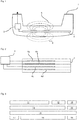
- Figure 3 shows a further embodiment in which a layer arrangement is shown on a multilayer board in stylized form. Such an arrangement can also be accommodated in a corresponding handle arrangement for the tailgate or the side door of a vehicle.
- Electrodes 11 to 19 formed on four different levels in the multilayer board. These electrode areas are in turn coupled to a control and evaluation device which is not shown here.
- the areas 13, 15 and 16 are coupled to a shield voltage, while the area 11 is connected as a sensor electrode.
- the lateral arrangement of the electrode areas 13 and 15, in addition to the electrode area 16, defines the effect of the sensor electrode 11 like a frame.
- the electrode 18 can be connected as a ground electrode.
- the electrodes are given different functions or other electrode areas are activated.
- the electrode 14 is provided with a shield voltage while the electrode 18 acts as a sensor electrode.
- the electrode areas 17 and 19 are coupled with the same potential as the electrode 14, so that here too the sensor electrode 18 is surrounded by a shielding voltage potential lying on the electrodes 14, 17 and 19.
- the electrode 16 can remain floating in this scheme, while the electrode 12 acts as a ground electrode, for example.
- the electrodes 12, 13, 15, 19 can be activated in order to cover a limited area.
- the electrode 19 and the area for a thumb rest can be placed on the handle. If the detection scheme for thumb rest detection is then activated, electrode 19 serves as a sensor, electrodes 18 and 16 serve as a shield electrode and electrode 15 serves as ground.
- both different electrode areas on the same level of a multilayer board and on different levels of the board are functionally controlled in a time-variable manner.
- Several electrode areas can be combined into functional units. It is essential that some of the electrode areas assume different functions in different control schemes.
Landscapes
- Engineering & Computer Science (AREA)
- Physics & Mathematics (AREA)
- General Physics & Mathematics (AREA)
- Computer Networks & Wireless Communication (AREA)
- Microelectronics & Electronic Packaging (AREA)
- Switches That Are Operated By Magnetic Or Electric Fields (AREA)
- Lock And Its Accessories (AREA)
- Measurement Of Length, Angles, Or The Like Using Electric Or Magnetic Means (AREA)
- Geophysics And Detection Of Objects (AREA)
- Electronic Switches (AREA)
Description
- Die Erfindung betrifft eine Sensoreinrichtung für ein Kraftfahrzeug, insbesondere eine Sensoreinrichtung zur kapazitiven Erfassung von Annäherungen eines Benutzers an die Sensoreinrichtung.
- Die Sensoreinrichtung ist mit wenigstens einer Mehrlagenplatine ausgebildet, die mehrere Metallisierungsebenen aufweist. Eine kapazitive Sensorelektrode ist zur Detektion auf einer der Metallisierungsebenen ausgebildet. Mit der Sensorelektrode ist eine Steuereinrichtung gekoppelt, um die Sensorelektrode mit einer elektrischen Spannung gegenüber einem Bezugspotenzial zu beaufschlagen. Eine Auswerteeinrichtung erfasst Kapazitätsänderungen an der Sensorelektrode, um Annäherung eines Benutzers an die Sensorelektrode zu detektieren. Steuereinrichtung und Auswerteeinrichtung können dabei zu einer Einrichtung integriert sein.
- Kapazitive Erfassungssysteme für Annäherungen sind in der Technik bekannt. Zwischen der Sensorelektrode, die auf ein vorgegebenes Potential gebracht wird und einer Referenzelektrode, z.B. der Fahrzeugmasse oder der Masse des unter dem Fahrzeug befindlichen Bodens bildet sich eine Kapazität aus. Diese Kapazität ist veränderbar, wenn sich in dem sensitiven Bereich der Sensoranordnung ein Körper bewegt, beispielsweise der Fuß eines Benutzers. Die Erfassung der Kapazität selbst ist in verschiedener Weise möglich. Beispielsweise kann als Messwert für die Kapazität eine Anzahl getakteter Entladevorgänge oder eine Entladezeitdauer verwendet werden. Beispielsweise ist auch aus der
DE 196 17 038A1 eine kapazitive Erfassung einer Annäherung an einen Fahrzeugtürgriff bekannt. - Die
DE 10 2012 109 034 A1 offenbart beispielsweise einen Fahrzeugtürgriff mit einer integrierten Sensoranordnung. Die Sensoranordnung verwendet eine mehrlagige Leiterplatte mit einer Sensorelektrode, die durch eine Mehrzahl von Leiterstrukturen in benachbarten Leiterplattenebenen mit Durchkontaktierungen gebildet ist. - Das Konzept der kapazitiven Annäherungsdetektion mit Hilfe einer Sensorelektrode, einer Schirmelektrode (auch Richtelektrode genannt) und einer Bezugselektrode ist ebenfalls in der Technik bekannt. Beispielsweise wird ein entsprechendes Konzept in der
EP 2 568 605 offenbart. Auch dieDE 10 2009 002 566 A1 offenbart eine Sensoranordnung mit verschiedenen Metallisierungsebenen und einer Sensorelektrode sowie einer Schirmelektrode. - Aus dem Dokumente
DE 102005055888 A1 ist eine kapazitive Sensoreinrichtung bekannt, welche mehrere Elektroden aufweist, die in Lagen angeordnet sind. Die Funktionen der Elektroden können paarweise getauscht werden. - Die
FR 2942637 A1 - Aus der
DE 10 2008 044 067 A1 ist ein kapazitiver Annäherungssensor mit Schirm- und Diagnoseelektrode bekannt. Die Anordnung bietet eine Diagnosefunktion, da die Erfassungsfunktion der Sensorelektrode bei einer Potenzialvorgabe an der Diagnoseelektrode überprüft werden kann. Die Sensorelektrode hat dabei in Abhängigkeit von dem Potenzial der Diagnoseelektrode vorgegebene Signale zu liefern, um die Diagnose zu bestehen. - Sensorelektroniken der genannten Art werden beispielsweise verwendet, um die Annäherung einer Hand des Benutzers eines Fahrzeuges an den Türgriff oder die Heckklappe eines Fahrzeuges zu erfassen. Wird eine solche Annäherung erfasst, wird beispielsweise ein Funkdialog mit einem Zugangsschlüssel für das Fahrzeug von einer fahrzeugseitigen Elektronik gestartet.
- Wie dem Stand der Technik und den vorstehend genannten Druckschriften zu entnehmen, wird die Sensorelektrode auf den Erfassungsbereich hin ausgerichtet.
- Auf der zum Erfassungsbereich abgewandten Seite wird eine Schirmelektrode platziert, wobei die Schirmelektrode in ihrem Potenzial der Sensorelektrode nachgeführt wird oder gegenüber diesem Potenzial variiert wird. Ausgewertet wird jedoch die Kapazitätsänderung der Sensorelektrode, nicht die der Schirmelektrode. Hinter der Schirmelektrode kann eine Masseelektrode platziert sein, um als Bezugspotenzial für die Kapazitätserfassung zu dienen.
- Moderne Fahrzeuge und Bediensysteme erfordern immer komplexere und auch flexiblere Bedienmöglichkeiten.
- Aufgabe der Erfindung ist es daher, eine verbesserte Sensoranordnung für eine kapazitive Annäherungserfassung bereitzustellen.
- Diese Aufgabe wird gelöst durch eine Sensoreinrichtung mit den Merkmalen des Patentanspruches 1.
- Wesentliches Merkmal der Erfindung ist es, eine Mehrlagenplatine mit mehreren Metallisierungsebenen zu verwenden, die Elektrodenbereiche in verschiedenen Ebenen aufnimmt. Als Mehrlagenplatine ist jede Platinenanordnung mit mehreren Metallisierungsebenen aufzufassen. Es kann z.B. eine einzelne Platine mit metallisierter Vorder- und Rückseite gebildet sein. Auch mehr als zwei Metallisierungsebenen sind im Rahmen der Erfindung verwendbar. Unter einer Mehrlagenplatine ist in diesem Zusammenhang auch der Verbund aus mehreren Einzelplatinen zu verstehen, die zu einer mehrlagigen Anordnung verbunden sind, z.B. über ein Pressfit Verfahren.
- Diese Elektrodenbereiche werden jedoch nicht mit einer starren Funktionalität ausgestattet. Verschiedene Elektrodenbereiche sind wechselnd ansteuerbar, so dass sie zeitweise unterschiedliche Funktionen erfüllen. In einer Art zeitlichen Multiplexbetrieb kann also ein Elektrodenbereich zeitweise als Sensorelektrode dienen und in einem anderen Zeitbereich und Erfassungsschema als Masseelektrode dienen oder als Schirmelektrode herangezogen werden. Die erfindungsgemäße Einrichtung weist mehrere Elektrodenbereiche auf, die sich beispielsweise teilweise überlappend in verschiedenen Ebenen befinden können und realisiert auf diese Weise mit zeitlich gemultiplexter Ansteuerung unterschiedliche Bedienschemata.
- Wesentlich ist, dass auf mehreren der Metallisierungsebenen jeweils wenigstens ein flächiger Elektrodenbereich ausgebildet ist. Jeder der für die Erfindung herangezogenen Elektrodenbereiche ist mit einer elektronischen Steuereinrichtung gekoppelt, welche die Elektrodenbereiche mit unterschiedlicher Spannung beaufschlagen kann.
- Eine Auswerteeinrichtung ist mit wenigstens einer Auswahl der Elektrodenbereiche gekoppelt, um Kapazitätsänderungen zu erfassen. Auswerteeinrichtung und Steuereinrichtung sind miteinander gekoppelt, um den Wechsel zwischen den Erfassungsschemata und den Ansteuerungen der Elektrodenbereichen zu synchronisieren. Sie können auch integriert ausgebildet sein, so dass eine Schaltung die Ansteuerung und die Auswertung realisiert. Eine Auswahl der Elektrodenbereiche wird mit unterschiedlichen Spannungen beaufschlagt und die Auswerteinrichtung wertet, je nach gerade aktuellem Ansteuerung-Auswerteschema, verschiedene Elektrodenbereiche als Sensorelektrode aus.
- Mit der erfindungsgemäßen Einrichtung brauchen nicht mehrere Sensoreinrichtungen für die Erfassung unterschiedlicher Bedienkonzepte realisiert werden. Diese Bedienkonzepte werden mit einer multifunktionalen Elektrodenanordnung auf einer Mehrlagenplatine realisiert. Es werden dabei in einer Ebene galvanisch getrennte Bereiche zur Ansteuerung ausgebildet, beispielsweise um Betätigungen in einen Griffbereich in Abhängigkeit vom Betätigungspunkt entlang der Griffachse zu erfassen. Außerdem können die Richtungen der Detektion, ausgehend von der Platine, verändert und umgekehrt werden. Dies ist möglich, indem beispielsweise die Lagen für die Sensorelektrode und die Schirmelektrode sowie die Masseelektrode ihre Reihenfolge vertauschen. Wird eine derartige Mehrlagenplatine also beispielsweise in einem Fahrzeugtürgriff angeordnet, so kann die Platine mit ihren Deckseiten einerseits in Richtung der Innenseite des Türgriffs und andererseits in Sichtrichtung der Außenseite orientiert werden. Durch den Wechsel der Funktionsebenen der Metallisierungsbereiche kann der Detektionsbereich einmal zur Innenseite des Türgriffes hin ausgerichtet werden und in einem zeitlichen Multiplexverfahren auch zeitweise zur Außenseite des Türgriffes. Beispielsweise können damit sowohl der Öffnungswunsch des Bedieners beim Eingreifen der Hand in die Innenseite der Tür als auch der Schließwunsch, beispielsweise beim Auflegen der Hand auf die Außenseite des Griffes, detektiert werden.
- In einer einfachen Gestaltung weist eine Platine zwei Metallisierungsebenen auf, deren Funktion als Sensorelektrode und Masseelektrode im zeitlichen Ablauf gewechselt wird, um die Detektionsrichtung umzusteuern. Eine andere einfache Gestaltung verwendet drei Metallisierungsebenen, von denen die mittlere als Schirmelektrode beibehalten wird, die außenliegenden Elektroden aber im zeitlichen Wechsel die Funktionen als Sensor- und Masseelektrode tauschen. Es wird im weiteren deutlich, dass auch eine größere Anzahl an Metallisierungsebenen verwendet werden kann.
- Erfindungsgemäß sind nicht nur in unterschiedlichen Ebenen der Mehrlagenplatinen Metallisierungsbereiche als Elektrodenbereiche für einen kapazitiven Sensor ausgebildet, es sind auch in einer Ebene mehrere getrennte Elektrodenbereiche ausgebildet, die einzeln ansteuerbar oder einzeln auswertbar sind.
- Grundsätzlich ist eine besonders gute Sensierung möglich, wenn eine als Sensor wirkende Elektrode, oder ein Sensorelektrodenverbund aus mehreren Elektrodenflächen, möglichst ganzflächig von einer Schirmelektrode geschirmt wird und diese Schirmung mit einer Masseelektrode geschützt ist. Entsprechend können die mehreren Elektrodenbereiche jeder Ebene derartige Sensorelektroden, Schirmelektroden oder Masseelektroden durch Zusammenschalten bilden.
- In einer solchen Gestaltung kann beispielsweise ein Detektionsbereich vorgesehen sein, der für die gezielte Betätigung durch Auflegen eines Daumens oder Fingers auf einen Griffabschnitt eine Detektion vornimmt.
- Solche getrennten Sensorelektroden in einer Ebene können, wie vorstehend erwähnt, in einem anderen Schema zusammen angesteuert werden, um eine gemeinsame Masseelektrode oder Schirmelektrode zu bilden.
- All diese verschiedenen Erfassungsschemata mit den wechselnden Elektrodenfunktionen können in zeitlicher Folge zyklisch durchlaufen werden. Allerdings kann auch eine zeitabhängige Ansteuerung dergestalt erfolgen, dass die Funktionen der Elektrodenbereiche in Abhängigkeit vom Fahrzeugzustand gewählt werden. Ist beispielsweise das Fahrzeug entriegelt, werden die Sensoren und Elektrodenbereiche derart angesteuert, dass nur eine Verriegelungsfunktion detektiert wird. Anders herum wird auf eine Entriegelungssensierung geschaltet, sofern das Fahrzeug sich im verriegelten Zustand befindet.
- Im Rahmen der Erfindung ist es durchaus möglich, mehrere Elektrodenbereiche auf unterschiedlichen Ebenen zu Funktionseinheiten zusammenzufassen, beispielsweise um sie in einen Zeitbereich mit derselben Funktionalität zu versehen und auch mit derselben Spannung zu beaufschlagen.
- Beispielsweise kann eine Schirmelektrode auf diese Weise über mehrere Ebenen der Mehrlagenplatine ausgedehnt werden und eine Sensorelektrode auf diese Weise gleichsam umklammern oder einfassen.
- Die Erfindung wird nun anhand der beiliegenden Zeichnung näher erläutert
Figur 1 zeigt einen stilisierten Türgriff 1 für ein Kraftfahrzeug, der mit einer erfindungsgemäßen Sensoranordnung ausgestattet ist. In dem Türgriff ist in der Handhabe, also dem zu umgreifenden Bereich bei der Türöffnung, eine Mehrlagenplatine 2 angeordnet. Auf der Mehrlagenplatine 2 sind mehrere Ebenen mit Sensorelektrodenbereichen ausgebildet, wie im Weiteren beschrieben wird. Eine Steuer- und Auswerteeinrichtung 3 ist mit der Platine 2 und den darauf angeordneten Elektrodenbereichen gekoppelt. Die Steuer- und Auswerteeinrichtung 3 ist über einen Kabelbaum mit der fahrzeugseitigen zentralen Steuereinheit verbunden. - In
Figur 1 ist das Wirkprinzip dargestellt, wonach mit ein und derselben Mehrlagenplatine 2 und auch denselben Elektrodenbereichen unterschiedliche Sensorfunktionen und Erfassungsbereiche erzielt werden. Bei Schaltung der Sensorelektroden durch die Steuer- und Auswerteeinrichtung 3 gemäß einem ersten Schema wird ein Detektionsbereich 5 realisiert, dessen Feldlinienbereich in derFigur 1 mit einer ersten gebrochenen Liniendarstellung angedeutet ist. Greift ein Benutzer in diesen Bereich im Inneren des Türgriffs hinein, so wird dies durch die Sensorelektrodenanordnung detektiert und eine entsprechende Fahrzeugfunktion kann ausgelöst werden. Schaltet die Steuer- und Auswerteeinrichtung 3 in die Sensorelektroden auf der Mehrlagenplatine 2 jedoch gemäß einem zweiten Schema an, so wird durch die Sensorelektroden ein Feldlinienverlauf 6 realisiert, der durch eine zweite Art von gebrochenen Linien dargestellt ist. Die Feldlinienverläufe 5 und 6 werden also zeitlich versetzt und nicht gleichzeitig realisiert. -
Figur 2 zeigt in vergrößerter schematischer Ansicht die Steuer- und Auswerteeinrichtung 3 und die Kopplung an die Mehrlagenplatine 2 und die darin angeordneten Elektrodenbereiche. In der Platine 2 sind mehrere Elektrodenebenen ausgebildet und metallisierte Elektrodenbereiche 4a, 4b, 4c und 4d angeordnet. Um die Feldlinienausbildung mit einem Detektionsbereich oberhalb der inFigur 2 dargestellten Platine zu realisieren wird beispielsweise Elektrode 4a als Sensorelektrode angesteuert, also mit einem vorgegebenen Spannung gegenüber einer Bezugselektrode beaufschlagt und durch die Auswerteschaltung überwacht. Die Elektrode 4b dient dann als Schirmelektrode, wobei sie beispielsweise auf demselben Potenzial geführt wird wie die Sensorelektrode 4a, jedoch Kapazitätsänderungen nur bei der Sensorelektrode 4a überwacht werden, nicht jedoch bei der Schirmelektrode 4b. Der Elektrodenbereich 4c wird in dieser Konfiguration potenzialfrei (floating) gehalten und der Elektrodenbereich 4d wird mit Masse gekoppelt. Auf diese Weise wird ein nach oben gerichteter Detektionsbereich realisiert (Bereich 5 inFig. 1 ). - Zeitlich versetzt oder durch rasche Umschaltung kann der Detektionsbereich in seiner Ausrichtung nach unten (Bereich 6 in
Fig. 1 ) verändert werden. In diesem Fall dient die Elektrode 4d als Sensorelektrode mit zugehörigem Potenzial und zugehöriger Auswertung. Die Elektrode 4c kann in diesem Beispiel potenzialfrei gehalten werden während die Elektrode 4b als Schirmelektrode auf demselben Potenzial geführt wie die Sensorelektrode 4d, jedoch ohne Kapazitätsüberwachung. Die Elektrode 4a kann gemäß diesem Schema mit dem Massepotenzial gekoppelt sein. - Es ist ersichtlich, dass dieselben Elektrodenbereiche in zeitlichem Versetz unterschiedliche Elektrodenfunktionalitäten übernehmen.
-
Figur 3 zeigt ein weiteres Ausführungsbeispiel, bei dem eine Schichtanordnung auf einer Mehrlagenplatine in stilisierter Form dargestellt ist. Eine solche Anordnung kann auch in einer entsprechenden Griffanordnung für die Heckklappe oder die Seitentür eines Fahrzeuges untergebracht werden. - Es sind Elektrodenbereiche 11 bis 19 auf vier unterschiedlichen Ebenen in der Mehrlagenplatine ausgebildet. Diese Elektrodenbereiche sind wiederum mit einer Steuer- und Auswerteeinrichtung gekoppelt welche hier nicht dargestellt ist.
- Gemäß einem ersten Funktionsschema werden mehrere Elektrodenbereiche, in diesem Beispiel die Bereiche 13, 15 und 16 mit einer Schirmspannung gekoppelt, während der Bereich 11 als Sensorelektrode geschaltet ist. Die seitliche Anordnung der Elektrodenbereiche 13 und 15, zusätzlich zu dem Elektrodenbereich 16 fasst die Wirkung der Sensorelektrode 11 rahmenartig ein. Die Elektrode 18 kann in diesem Schema als Masseelektrode geschaltet sein.
- In einem zweiten Schema, welches zeitversetzt zu dem vorangehend beschriebenen Schema aktiviert wird, erhalten die Elektroden andere Funktionen oder werden andere Elektrodenbereiche aktiviert. In diesem anderen Schema wird beispielsweise die Elektrode 14 mit einer Schirmspannung versehen während die Elektrode 18 als Sensorelektrode wirkt. Die Elektrodenbereiche 17 und 19 sind mit demselben Potenzial gekoppelt wie die Elektrode 14, so dass auch hier die Sensorelektrode 18 von einem Schirmspannungspotenzial, liegend an den Elektroden 14, 17 und 19 eingefasst ist. Die Elektrode 16 kann in diesem Schema potentialfrei bleiben, während beispielsweise die Elektrode 12 als Masseelektrode wirkt.
- Gemäß einem zeitlich versetzt aktivierbaren weiteren Schema können die Elektroden 12, 13, 15, 19 aktiviert werden, um einen begrenzten Bereich zu erfassen. Beispielsweise kann die Elektrode 19 und dem Bereich für eine Daumenauflage am Griff platziert sein. Wird dann das Erfassungsschema zur Daumenauflageerkennung aktiviert, so dient Elektrode 19 als Sensor, die Elektroden 18 und 16 dienen als Schirmelektrode und Elektrode 15 dient als Masse.
- Es ist ersichtlich, dass gemäß der Erfindung sowohl unterschiedliche Elektrodenbereiche auf derselben Ebene einer Mehrlagenplatine als auch auf unterschiedlichen Ebenen der Platine in zeitlich veränderbarer Weise funktional angesteuert werden. Mehrere Elektrodenbereiche können dabei zu Funktionseinheiten zusammengefasst werden. Wesentlich ist, dass einige der Elektrodenbereiche in unterschiedlichen Ansteuerungsschemata unterschiedliche Funktionen übernehmen.
Claims (6)
- Sensoreinrichtung für ein Kraftfahrzeug, mit einer Mehrlagenplatine (2), auf der mehrere Metallisierungsebenen ausgebildet sind,
wobei eine kapazitive Sensorelektrode zur Detektion mit Hilfe einer kapazitiven Annäherungserfassung auf einer der Metallisierungsebenen ausgebildet ist,
wobei eine Steuereinrichtung (3) mit der Sensorelektrode gekoppelt ist, um die Sensorelektrode mit einer elektrischen Spannung gegenüber einem Bezugspotenzial zu beaufschlagen und eine Auswerteeinrichtung (3) eine Kapazitätsänderung der Sensorelektrode erfasst, um Annäherungen eines Benutzers an die Sensorelektrode zu detektieren, wobei auf mehreren der Metallisierungsebenen jeweils wenigstens ein flächiger Elektrodenbereich (11, 12, 13, 14, 15, 16, 17, 18, 19) ausgebildet ist, wobei jeder der Elektrodenbereiche mit der Steuereinrichtung (3) gekoppelt ist, so dass jeder der Elektrodenbereiche mit einer zugeordneten, individuellen elektrischen Spannung gegenüber einem Bezugspotenzial zu beaufschlagen ist,
wobei die Auswerteeinrichtung (3) mit wenigstens zwei der Elektrodenbereiche auf unterschiedlichen Metallisierungsebenen gekoppelt ist,
wobei die Auswerteeinrichtung und die Steuereinrichtung derart ausgebildet sind, dass wenigstens zwei der Elektrodenbereiche auf unterschiedlichen Metallisierungsebenen zeitlich abwechselnd als Sensorelektrode angesteuert und ausgewertet werden und wenigstens zwei der Elektrodenbereiche auf unterschiedlichen Metallisierungsebenen zeitlich abwechselnd als Masse angesteuert und ausgewertet werden, wobei in wenigstens einer Metallisierungsebene zwei getrennte Elektrodenbereiche (11, 12, 13; 14, 15; 17, 18, 19) ausgebildet sind, welche getrennt ansteuerbar oder auswertbar sind,
wobei die Steuerschaltung derart ausgebildet ist, dass wenigstens einer der gekoppelten Elektrodenbereiche zweitweise potenzialfrei (floating) schaltbar ist. - Sensoreinrichtung nach Anspruch 1, wobei die zwei Elektrodenbereiche auf unterschiedlichen Metallisierungsebenen welche abwechselnd als Sensorelektrode und Masseelektrode ansteuerbar sind identisch sind, so dass jede der Elektroden zeitweise als Sensorelektrode und zeitweise als Masseelektrode ansteuerbar ist.
- Sensoranordnung nach einem der vorangehenden Ansprüche, wobei die Steuereinrichtung und die Auswerteeinrichtung derart ausgebildet sind, dass zeitversetzt Elektrodenbereiche in verschiedenen Ebenen der Mehrlagenplatine als Sensorelektrode geschaltet sind.
- Sensoranordnung nach Anspruch 3, wobei die Steuereinrichtung und die Auswerteeinrichtung ausgebildet sind, so dass zunächst
ein Elektrodenbereich (4a) als Sensorelektrode geschaltet ist, dessen Ebene der Mehrlagenplatine einen ersten Abstand von einer ersten Außenseite der Mehrlagenplatine aufweist und gleichzeitig ein anderer Elektrodenbereich (4c) als Schirmelektrode geschaltet ist, dessen Ebene der Mehrlagenplatine einen zweiten Abstand von der Außenseite aufweist, wobei der zweite Abstand größer als der erste Abstand ist,
und zeitlich versetzt
ein Elektrodenbereich (4c) als Sensorelektrode geschaltet ist, dessen Ebene der Mehrlagenplatine einen dritten Abstand von der ersten Außenseite der Mehrlagenplatine aufweist, wobei der dritte Abstand größer als der erste Abstand ist,
und gleichzeitig ein anderer Elektrodenbereich (4b) als Schirmelektrode geschaltet ist, dessen Ebene der Mehrlagenplatine einen vierten Abstand von der Außenseite aufweist, wobei der vierte Abstand kleiner als der dritte Abstand ist,
so dass zeitlich versetzt die räumliche Abfolge von Sensorelektrode und Schirmelektrode gegenüber der Außenseite umgekehrt wird. - Sensoranordnung nach einem der vorangehenden Ansprüche, wobei die Elektrodenbereiche wenigstens paarweise und wenigstens teilweise in einer Richtung senkrecht zu der Platinenebene überlappen.
- Sensoranordnung nach einem der vorangehenden Ansprüche, wobei wenigstens ein Elektrodenbereich in einer Ebene als Sensorelektrode schaltbar ist, ein Elektrodenbereich in einer anderen Ebene als Schirmelektrode schaltbar ist und ein Elektrodenbereich in einer weiteren, anderen Ebene als Masseelektrode schaltbar ist.
Applications Claiming Priority (2)
| Application Number | Priority Date | Filing Date | Title |
|---|---|---|---|
| DE102014107559.5A DE102014107559A1 (de) | 2014-05-28 | 2014-05-28 | Sensoreinrichtung für ein Kraftfahrzeug |
| PCT/EP2015/060097 WO2015180942A1 (de) | 2014-05-28 | 2015-05-07 | Sensoreinrichtung für ein kraftfahrzeug |
Publications (2)
| Publication Number | Publication Date |
|---|---|
| EP3149855A1 EP3149855A1 (de) | 2017-04-05 |
| EP3149855B1 true EP3149855B1 (de) | 2020-12-16 |
Family
ID=53181277
Family Applications (1)
| Application Number | Title | Priority Date | Filing Date |
|---|---|---|---|
| EP15722998.0A Active EP3149855B1 (de) | 2014-05-28 | 2015-05-07 | Sensoreinrichtung für ein kraftfahrzeug |
Country Status (7)
| Country | Link |
|---|---|
| US (1) | US9948295B2 (de) |
| EP (1) | EP3149855B1 (de) |
| JP (1) | JP6546608B2 (de) |
| KR (1) | KR102247700B1 (de) |
| CN (1) | CN106414877B (de) |
| DE (1) | DE102014107559A1 (de) |
| WO (1) | WO2015180942A1 (de) |
Families Citing this family (24)
| Publication number | Priority date | Publication date | Assignee | Title |
|---|---|---|---|---|
| DE102012107115A1 (de) * | 2012-08-02 | 2014-02-06 | Brose Fahrzeugteile Gmbh & Co. Kommanditgesellschaft, Hallstadt | Verfahren zur Steuerung eines kapazitiven Einklemmschutzsystems und Einklemmschutzsystem |
| DE102016115109A1 (de) | 2016-08-15 | 2018-02-15 | Huf Hülsbeck & Fürst Gmbh & Co. Kg | Kapazitive Sensorvorrichtung mit verbesserter Störtoleranz |
| DE102016215570A1 (de) * | 2016-08-19 | 2018-02-22 | Ifm Electronic Gmbh | Auswerteschaltung für einen kapazitiven Sensor, kapazitiver Sensor und Aktor in einem Kraftfahrzeug |
| JP6851250B2 (ja) * | 2017-04-28 | 2021-03-31 | 株式会社ユーシン | 車両用ドアハンドル装置 |
| US11128298B2 (en) * | 2017-06-27 | 2021-09-21 | Semtech Corporation | Advanced capacitive proximity sensor |
| DE102017121795A1 (de) * | 2017-09-20 | 2019-03-21 | Huf Hülsbeck & Fürst Gmbh & Co. Kg | System und Verfahren zur Detektion einer Aktivierungshandlung |
| CN111615578B (zh) * | 2018-01-17 | 2022-07-29 | 阿尔卑斯阿尔派株式会社 | 门把手 |
| US10378254B1 (en) * | 2018-05-16 | 2019-08-13 | Ford Global Technologies, Llc | Vehicle door handle having proximity sensors for door control and keypad |
| US10633910B2 (en) | 2018-05-16 | 2020-04-28 | Ford Global Technologies, Llc | Vehicle door having variable speed power assist |
| US11078691B2 (en) | 2018-06-26 | 2021-08-03 | Ford Global Technologies, Llc | Deployable vehicle door handle |
| JP6967669B2 (ja) * | 2018-08-15 | 2021-11-17 | アルプスアルパイン株式会社 | ドアハンドル |
| FR3087469B1 (fr) * | 2018-10-19 | 2020-09-25 | Continental Automotive France | Dispositif de detection d'intention de verrouiller ou de deverrouiller une portiere de vehicule automobile et procede associe |
| EP3651361A1 (de) * | 2018-11-06 | 2020-05-13 | Huf Hülsbeck & Fürst GmbH & Co. KG | Sensorvorrichtung |
| DE102018130789A1 (de) | 2018-12-04 | 2020-06-04 | Huf Hülsbeck & Fürst Gmbh & Co. Kg | Fahrzeugtürgriff mit Sensoreinrichtung und drahtloser Kommunikationseinrichtung |
| DE102018130791A1 (de) | 2018-12-04 | 2020-06-04 | Huf Hülsbeck & Fürst Gmbh & Co. Kg | Fahrzeugtürgriff mit Sensoreinrichtung und drahtloser Kommunikationseinrichtung |
| DE102019124217A1 (de) * | 2019-06-11 | 2020-12-17 | Huf Hülsbeck & Fürst Gmbh & Co. Kg | Anordnung |
| DE102019124221A1 (de) * | 2019-06-11 | 2020-12-17 | Huf Hülsbeck & Fürst Gmbh & Co. Kg | Anordnung |
| JP7216963B2 (ja) * | 2019-10-03 | 2023-02-02 | 本田技研工業株式会社 | 静電容量型検知センサ、静電容量型検知センサモジュールおよび静電容量型検知センサを用いた状態判定方法 |
| DE102019132134A1 (de) * | 2019-11-27 | 2021-05-27 | Huf Hülsbeck & Fürst Gmbh & Co. Kg | Vorrichtung für ein Fahrzeug zur Detektion einer Aktivierungshandlung in einem Detektionsbereich |
| DE102020102887A1 (de) * | 2020-02-05 | 2021-08-05 | Huf Hülsbeck & Fürst Gmbh & Co. Kg | Betätigungsvorrichtung mit Verkleidungselement, Fahrzeug, sowie Verfahren |
| WO2021235052A1 (ja) * | 2020-05-19 | 2021-11-25 | アルプスアルパイン株式会社 | 静電入力装置 |
| DE102020127438A1 (de) * | 2020-10-19 | 2022-04-21 | Huf Hülsbeck & Fürst Gmbh & Co. Kg | System zur Detektion einer Aktivierungshandlung in einem Aktivierungsbereich für ein Fahrzeug |
| US11573102B2 (en) * | 2020-11-17 | 2023-02-07 | Ford Global Technologies, Llc | Method of manufacturing multi-layer electrode for a capacitive pressure sensor and multi-layer electrodes formed therefrom |
| DE102022203459A1 (de) * | 2022-04-06 | 2023-10-12 | Brose Fahrzeugteile Se & Co. Kommanditgesellschaft, Bamberg | Baugruppe eines Fahrzeugs mit einem an einer Fahrzeugtür angeordneten Bedienelement |
Citations (1)
| Publication number | Priority date | Publication date | Assignee | Title |
|---|---|---|---|---|
| DE102008044067A1 (de) * | 2008-11-25 | 2010-05-27 | Huf Hülsbeck & Fürst Gmbh & Co. Kg | Kapazitiver Annäherungssensor mit einer Schirmelektrode und einer Diagnoseelektrode |
Family Cites Families (15)
| Publication number | Priority date | Publication date | Assignee | Title |
|---|---|---|---|---|
| DE19617038C2 (de) | 1996-04-27 | 2000-11-30 | Huf Huelsbeck & Fuerst Gmbh | Schließsystem, insbesondere für Kraftfahrzeuge |
| DE10051055A1 (de) * | 2000-10-14 | 2002-05-02 | Bosch Gmbh Robert | Vorrichtung zum Einleiten eines Öffnungs- und Verriegelungsvorgangs eines Kraftfahrzeugs |
| JP2008520864A (ja) * | 2004-11-23 | 2008-06-19 | イデント テクノロジー アーゲー | 存在検出に適した合成音声を含む信号処理シーケンスを実行するシステム及びシステムの構成要素 |
| DE102005055888A1 (de) * | 2004-11-23 | 2007-11-15 | Ident Technology Ag | System und dessen Komponenten zur Abwicklung von Signalverarbeitungsabläufen unter Einbeziehung einer zur Präsenzerfassung geeigneten synthetischen Aura |
| EP2017139A1 (de) * | 2007-07-17 | 2009-01-21 | IEE International Electronics & Engineering S.A.R.L. | Insassendetektionssystem für ein Kraftfahrzeug |
| FR2942637B1 (fr) * | 2009-03-02 | 2015-09-04 | Valeo Securite Habitacle | Poignee d'un ouvrant de vehicule automobile |
| JP2010236329A (ja) * | 2009-03-31 | 2010-10-21 | Fujikura Ltd | 車両用ドア開閉角度制御装置 |
| DE102009002566A1 (de) * | 2009-04-22 | 2010-10-28 | Huf Hülsbeck & Fürst Gmbh & Co. Kg | Sensorelektronik in einem Kraftfahrzeugtürgriff |
| US8806572B2 (en) * | 2009-05-30 | 2014-08-12 | Cisco Technology, Inc. | Authentication via monitoring |
| JP4817027B2 (ja) * | 2009-06-16 | 2011-11-16 | 株式会社デンソー | 静電式乗員検知装置 |
| US9051769B2 (en) * | 2009-08-21 | 2015-06-09 | Uusi, Llc | Vehicle assembly having a capacitive sensor |
| DE102010026562B4 (de) * | 2010-07-08 | 2024-09-26 | HELLA GmbH & Co. KGaA | Sensoranordnung zur Erfassung von Umgebungsbedingungen sowie Kraftfahrzeug mit der Sensoranordnung |
| DE102011053314A1 (de) | 2011-09-06 | 2013-03-07 | Huf Hülsbeck & Fürst Gmbh & Co. Kg | Kapazitive Sensoranordnung |
| DE102012107284A1 (de) * | 2012-08-08 | 2014-02-13 | Brose Fahrzeugteile Gmbh & Co. Kommanditgesellschaft, Hallstadt | Steuerungsverfahren und Steuerungssystem für ein Fahrzeugschließelement |
| DE102012109034A1 (de) | 2012-09-25 | 2014-03-27 | Huf Hülsbeck & Fürst Gmbh & Co. Kg | Kraftfahrzeugtürgriff mit Sensorelektronik |
-
2014
- 2014-05-28 DE DE102014107559.5A patent/DE102014107559A1/de not_active Withdrawn
-
2015
- 2015-05-07 EP EP15722998.0A patent/EP3149855B1/de active Active
- 2015-05-07 KR KR1020167036083A patent/KR102247700B1/ko not_active Expired - Fee Related
- 2015-05-07 JP JP2016570043A patent/JP6546608B2/ja not_active Expired - Fee Related
- 2015-05-07 CN CN201580028113.5A patent/CN106414877B/zh active Active
- 2015-05-07 WO PCT/EP2015/060097 patent/WO2015180942A1/de not_active Ceased
- 2015-05-07 US US15/313,771 patent/US9948295B2/en active Active
Patent Citations (1)
| Publication number | Priority date | Publication date | Assignee | Title |
|---|---|---|---|---|
| DE102008044067A1 (de) * | 2008-11-25 | 2010-05-27 | Huf Hülsbeck & Fürst Gmbh & Co. Kg | Kapazitiver Annäherungssensor mit einer Schirmelektrode und einer Diagnoseelektrode |
Also Published As
| Publication number | Publication date |
|---|---|
| JP2017524904A (ja) | 2017-08-31 |
| DE102014107559A1 (de) | 2015-12-03 |
| WO2015180942A1 (de) | 2015-12-03 |
| KR102247700B1 (ko) | 2021-05-04 |
| CN106414877B (zh) | 2019-03-08 |
| US9948295B2 (en) | 2018-04-17 |
| KR20170013911A (ko) | 2017-02-07 |
| EP3149855A1 (de) | 2017-04-05 |
| US20170194960A1 (en) | 2017-07-06 |
| CN106414877A (zh) | 2017-02-15 |
| JP6546608B2 (ja) | 2019-07-17 |
Similar Documents
| Publication | Publication Date | Title |
|---|---|---|
| EP3149855B1 (de) | Sensoreinrichtung für ein kraftfahrzeug | |
| EP3036833B1 (de) | Einrichtung zum berührungslosen betätigen einer fahrzeugtür | |
| DE102014016422A1 (de) | Vorrichtung und Verfahren zur Erfassung einer Lenkradberührung | |
| WO2016037782A1 (de) | Türgriffanordnung für ein kraftfahrzeug | |
| DE102019112802A1 (de) | Fahrzeugtür aufweisend ein antriebsassistenzsystem mit variabler geschwindigkeit | |
| EP2711488B1 (de) | Kraftfahrzeugtürgriff mit sensorelektronik | |
| DE102017120393A1 (de) | Zugangssystem für ein Fahrzeug | |
| DE102014117823A1 (de) | Lenkrad für ein Kraftfahrzeug mit einem Sensorsystem und Verfahren zum Erkennen einer Anwesenheit einer menschlichen Hand in einem Greifbereich eines solchen Lenkrads | |
| EP2828973B1 (de) | Kapazitive sensoranordnung zur schaltung einer türöffnung an einem kraftfahrzeug und zugehöriges verfahren | |
| DE102013014824A1 (de) | Kapazitiver Sensor für ein Fahrzeug | |
| DE112019005884T5 (de) | Sensoranordnung zur kapazitiven Positionserfassung einer Hand an einem Lenkrad | |
| DE102017121795A1 (de) | System und Verfahren zur Detektion einer Aktivierungshandlung | |
| EP1997984B1 (de) | Kraftfahrzeugtürgriff mit Annäherungssensor | |
| WO2012156042A1 (de) | Kraftfahrzeug mit kapazitivem deformationssensor zur kollisionsdetektion | |
| WO2016102236A1 (de) | Vorrichtung zur berührungslosen betätigung eines verstellbaren fahrzeugteils | |
| EP3629478B1 (de) | Sensorvorrichtung zur detektion einer aktivierungshandlung bei einem fahrzeug | |
| EP3394983B1 (de) | Verfahren zum betreiben eines sensorsystems, sensorelement sowie sensorsystem | |
| EP2974023B1 (de) | Kapazitive sensoranordnung mit schirmelektrode | |
| DE102013021823A1 (de) | Vorrichtung zum Erfassen einer elektrodermalen Aktivität einer Person, Lenkrad, Kraftfahrzeug und entsprechendes Verfahren | |
| EP3472935B1 (de) | Kapazitive sensorvorrichtung mit verbesserter störtoleranz | |
| DE102012022927A1 (de) | Kapazitiver Näherungssensor | |
| DE102018131379A1 (de) | Sensorvorrichtung zur Detektion einer Aktivierungshandlung bei einem Fahrzeug | |
| EP3182860B1 (de) | Möbel mit sensoreinrichtung | |
| EP3457569B1 (de) | Auswerteanordnung für eine kapazitive sensorvorrichtung | |
| DE102012105363A1 (de) | Sensoranordnung zur Betätigungserfassung an einem Kraftfahrzeug |
Legal Events
| Date | Code | Title | Description |
|---|---|---|---|
| STAA | Information on the status of an ep patent application or granted ep patent |
Free format text: STATUS: THE INTERNATIONAL PUBLICATION HAS BEEN MADE |
|
| PUAI | Public reference made under article 153(3) epc to a published international application that has entered the european phase |
Free format text: ORIGINAL CODE: 0009012 |
|
| STAA | Information on the status of an ep patent application or granted ep patent |
Free format text: STATUS: REQUEST FOR EXAMINATION WAS MADE |
|
| 17P | Request for examination filed |
Effective date: 20170102 |
|
| AK | Designated contracting states |
Kind code of ref document: A1 Designated state(s): AL AT BE BG CH CY CZ DE DK EE ES FI FR GB GR HR HU IE IS IT LI LT LU LV MC MK MT NL NO PL PT RO RS SE SI SK SM TR |
|
| AX | Request for extension of the european patent |
Extension state: BA ME |
|
| DAV | Request for validation of the european patent (deleted) | ||
| DAX | Request for extension of the european patent (deleted) | ||
| STAA | Information on the status of an ep patent application or granted ep patent |
Free format text: STATUS: EXAMINATION IS IN PROGRESS |
|
| 17Q | First examination report despatched |
Effective date: 20190320 |
|
| GRAP | Despatch of communication of intention to grant a patent |
Free format text: ORIGINAL CODE: EPIDOSNIGR1 |
|
| STAA | Information on the status of an ep patent application or granted ep patent |
Free format text: STATUS: GRANT OF PATENT IS INTENDED |
|
| RIC1 | Information provided on ipc code assigned before grant |
Ipc: G07C 9/00 20200101ALI20200903BHEP Ipc: H03K 17/96 20060101ALI20200903BHEP Ipc: H03K 17/955 20060101AFI20200903BHEP Ipc: E05B 81/76 20140101ALI20200903BHEP |
|
| INTG | Intention to grant announced |
Effective date: 20200924 |
|
| GRAS | Grant fee paid |
Free format text: ORIGINAL CODE: EPIDOSNIGR3 |
|
| GRAA | (expected) grant |
Free format text: ORIGINAL CODE: 0009210 |
|
| STAA | Information on the status of an ep patent application or granted ep patent |
Free format text: STATUS: THE PATENT HAS BEEN GRANTED |
|
| AK | Designated contracting states |
Kind code of ref document: B1 Designated state(s): AL AT BE BG CH CY CZ DE DK EE ES FI FR GB GR HR HU IE IS IT LI LT LU LV MC MK MT NL NO PL PT RO RS SE SI SK SM TR |
|
| REG | Reference to a national code |
Ref country code: GB Ref legal event code: FG4D Free format text: NOT ENGLISH |
|
| REG | Reference to a national code |
Ref country code: IE Ref legal event code: FG4D Free format text: LANGUAGE OF EP DOCUMENT: GERMAN |
|
| REG | Reference to a national code |
Ref country code: DE Ref legal event code: R096 Ref document number: 502015014015 Country of ref document: DE |
|
| REG | Reference to a national code |
Ref country code: AT Ref legal event code: REF Ref document number: 1346527 Country of ref document: AT Kind code of ref document: T Effective date: 20210115 |
|
| PG25 | Lapsed in a contracting state [announced via postgrant information from national office to epo] |
Ref country code: NO Free format text: LAPSE BECAUSE OF FAILURE TO SUBMIT A TRANSLATION OF THE DESCRIPTION OR TO PAY THE FEE WITHIN THE PRESCRIBED TIME-LIMIT Effective date: 20210316 Ref country code: FI Free format text: LAPSE BECAUSE OF FAILURE TO SUBMIT A TRANSLATION OF THE DESCRIPTION OR TO PAY THE FEE WITHIN THE PRESCRIBED TIME-LIMIT Effective date: 20201216 Ref country code: RS Free format text: LAPSE BECAUSE OF FAILURE TO SUBMIT A TRANSLATION OF THE DESCRIPTION OR TO PAY THE FEE WITHIN THE PRESCRIBED TIME-LIMIT Effective date: 20201216 Ref country code: GR Free format text: LAPSE BECAUSE OF FAILURE TO SUBMIT A TRANSLATION OF THE DESCRIPTION OR TO PAY THE FEE WITHIN THE PRESCRIBED TIME-LIMIT Effective date: 20210317 |
|
| REG | Reference to a national code |
Ref country code: NL Ref legal event code: MP Effective date: 20201216 |
|
| PG25 | Lapsed in a contracting state [announced via postgrant information from national office to epo] |
Ref country code: LV Free format text: LAPSE BECAUSE OF FAILURE TO SUBMIT A TRANSLATION OF THE DESCRIPTION OR TO PAY THE FEE WITHIN THE PRESCRIBED TIME-LIMIT Effective date: 20201216 Ref country code: SE Free format text: LAPSE BECAUSE OF FAILURE TO SUBMIT A TRANSLATION OF THE DESCRIPTION OR TO PAY THE FEE WITHIN THE PRESCRIBED TIME-LIMIT Effective date: 20201216 Ref country code: BG Free format text: LAPSE BECAUSE OF FAILURE TO SUBMIT A TRANSLATION OF THE DESCRIPTION OR TO PAY THE FEE WITHIN THE PRESCRIBED TIME-LIMIT Effective date: 20210316 |
|
| PG25 | Lapsed in a contracting state [announced via postgrant information from national office to epo] |
Ref country code: NL Free format text: LAPSE BECAUSE OF FAILURE TO SUBMIT A TRANSLATION OF THE DESCRIPTION OR TO PAY THE FEE WITHIN THE PRESCRIBED TIME-LIMIT Effective date: 20201216 Ref country code: HR Free format text: LAPSE BECAUSE OF FAILURE TO SUBMIT A TRANSLATION OF THE DESCRIPTION OR TO PAY THE FEE WITHIN THE PRESCRIBED TIME-LIMIT Effective date: 20201216 |
|
| REG | Reference to a national code |
Ref country code: LT Ref legal event code: MG9D |
|
| PG25 | Lapsed in a contracting state [announced via postgrant information from national office to epo] |
Ref country code: SK Free format text: LAPSE BECAUSE OF FAILURE TO SUBMIT A TRANSLATION OF THE DESCRIPTION OR TO PAY THE FEE WITHIN THE PRESCRIBED TIME-LIMIT Effective date: 20201216 Ref country code: PT Free format text: LAPSE BECAUSE OF FAILURE TO SUBMIT A TRANSLATION OF THE DESCRIPTION OR TO PAY THE FEE WITHIN THE PRESCRIBED TIME-LIMIT Effective date: 20210416 Ref country code: RO Free format text: LAPSE BECAUSE OF FAILURE TO SUBMIT A TRANSLATION OF THE DESCRIPTION OR TO PAY THE FEE WITHIN THE PRESCRIBED TIME-LIMIT Effective date: 20201216 Ref country code: LT Free format text: LAPSE BECAUSE OF FAILURE TO SUBMIT A TRANSLATION OF THE DESCRIPTION OR TO PAY THE FEE WITHIN THE PRESCRIBED TIME-LIMIT Effective date: 20201216 Ref country code: CZ Free format text: LAPSE BECAUSE OF FAILURE TO SUBMIT A TRANSLATION OF THE DESCRIPTION OR TO PAY THE FEE WITHIN THE PRESCRIBED TIME-LIMIT Effective date: 20201216 Ref country code: EE Free format text: LAPSE BECAUSE OF FAILURE TO SUBMIT A TRANSLATION OF THE DESCRIPTION OR TO PAY THE FEE WITHIN THE PRESCRIBED TIME-LIMIT Effective date: 20201216 Ref country code: SM Free format text: LAPSE BECAUSE OF FAILURE TO SUBMIT A TRANSLATION OF THE DESCRIPTION OR TO PAY THE FEE WITHIN THE PRESCRIBED TIME-LIMIT Effective date: 20201216 |
|
| PGFP | Annual fee paid to national office [announced via postgrant information from national office to epo] |
Ref country code: FR Payment date: 20210521 Year of fee payment: 7 |
|
| PG25 | Lapsed in a contracting state [announced via postgrant information from national office to epo] |
Ref country code: PL Free format text: LAPSE BECAUSE OF FAILURE TO SUBMIT A TRANSLATION OF THE DESCRIPTION OR TO PAY THE FEE WITHIN THE PRESCRIBED TIME-LIMIT Effective date: 20201216 |
|
| PGFP | Annual fee paid to national office [announced via postgrant information from national office to epo] |
Ref country code: GB Payment date: 20210526 Year of fee payment: 7 |
|
| REG | Reference to a national code |
Ref country code: DE Ref legal event code: R097 Ref document number: 502015014015 Country of ref document: DE |
|
| PG25 | Lapsed in a contracting state [announced via postgrant information from national office to epo] |
Ref country code: IS Free format text: LAPSE BECAUSE OF FAILURE TO SUBMIT A TRANSLATION OF THE DESCRIPTION OR TO PAY THE FEE WITHIN THE PRESCRIBED TIME-LIMIT Effective date: 20210416 |
|
| PLBE | No opposition filed within time limit |
Free format text: ORIGINAL CODE: 0009261 |
|
| STAA | Information on the status of an ep patent application or granted ep patent |
Free format text: STATUS: NO OPPOSITION FILED WITHIN TIME LIMIT |
|
| PG25 | Lapsed in a contracting state [announced via postgrant information from national office to epo] |
Ref country code: IT Free format text: LAPSE BECAUSE OF FAILURE TO SUBMIT A TRANSLATION OF THE DESCRIPTION OR TO PAY THE FEE WITHIN THE PRESCRIBED TIME-LIMIT Effective date: 20201216 Ref country code: AL Free format text: LAPSE BECAUSE OF FAILURE TO SUBMIT A TRANSLATION OF THE DESCRIPTION OR TO PAY THE FEE WITHIN THE PRESCRIBED TIME-LIMIT Effective date: 20201216 |
|
| 26N | No opposition filed |
Effective date: 20210917 |
|
| PG25 | Lapsed in a contracting state [announced via postgrant information from national office to epo] |
Ref country code: ES Free format text: LAPSE BECAUSE OF FAILURE TO SUBMIT A TRANSLATION OF THE DESCRIPTION OR TO PAY THE FEE WITHIN THE PRESCRIBED TIME-LIMIT Effective date: 20201216 Ref country code: DK Free format text: LAPSE BECAUSE OF FAILURE TO SUBMIT A TRANSLATION OF THE DESCRIPTION OR TO PAY THE FEE WITHIN THE PRESCRIBED TIME-LIMIT Effective date: 20201216 |
|
| REG | Reference to a national code |
Ref country code: CH Ref legal event code: PL |
|
| PG25 | Lapsed in a contracting state [announced via postgrant information from national office to epo] |
Ref country code: MC Free format text: LAPSE BECAUSE OF FAILURE TO SUBMIT A TRANSLATION OF THE DESCRIPTION OR TO PAY THE FEE WITHIN THE PRESCRIBED TIME-LIMIT Effective date: 20201216 Ref country code: LI Free format text: LAPSE BECAUSE OF NON-PAYMENT OF DUE FEES Effective date: 20210531 Ref country code: LU Free format text: LAPSE BECAUSE OF NON-PAYMENT OF DUE FEES Effective date: 20210507 Ref country code: CH Free format text: LAPSE BECAUSE OF NON-PAYMENT OF DUE FEES Effective date: 20210531 |
|
| REG | Reference to a national code |
Ref country code: BE Ref legal event code: MM Effective date: 20210531 |
|
| PG25 | Lapsed in a contracting state [announced via postgrant information from national office to epo] |
Ref country code: SI Free format text: LAPSE BECAUSE OF FAILURE TO SUBMIT A TRANSLATION OF THE DESCRIPTION OR TO PAY THE FEE WITHIN THE PRESCRIBED TIME-LIMIT Effective date: 20201216 |
|
| PG25 | Lapsed in a contracting state [announced via postgrant information from national office to epo] |
Ref country code: IE Free format text: LAPSE BECAUSE OF NON-PAYMENT OF DUE FEES Effective date: 20210507 |
|
| PG25 | Lapsed in a contracting state [announced via postgrant information from national office to epo] |
Ref country code: IS Free format text: LAPSE BECAUSE OF FAILURE TO SUBMIT A TRANSLATION OF THE DESCRIPTION OR TO PAY THE FEE WITHIN THE PRESCRIBED TIME-LIMIT Effective date: 20210416 |
|
| REG | Reference to a national code |
Ref country code: AT Ref legal event code: MM01 Ref document number: 1346527 Country of ref document: AT Kind code of ref document: T Effective date: 20210507 |
|
| PG25 | Lapsed in a contracting state [announced via postgrant information from national office to epo] |
Ref country code: BE Free format text: LAPSE BECAUSE OF NON-PAYMENT OF DUE FEES Effective date: 20210531 |
|
| PG25 | Lapsed in a contracting state [announced via postgrant information from national office to epo] |
Ref country code: AT Free format text: LAPSE BECAUSE OF NON-PAYMENT OF DUE FEES Effective date: 20210507 |
|
| GBPC | Gb: european patent ceased through non-payment of renewal fee |
Effective date: 20220507 |
|
| PG25 | Lapsed in a contracting state [announced via postgrant information from national office to epo] |
Ref country code: FR Free format text: LAPSE BECAUSE OF NON-PAYMENT OF DUE FEES Effective date: 20220531 |
|
| PG25 | Lapsed in a contracting state [announced via postgrant information from national office to epo] |
Ref country code: HU Free format text: LAPSE BECAUSE OF FAILURE TO SUBMIT A TRANSLATION OF THE DESCRIPTION OR TO PAY THE FEE WITHIN THE PRESCRIBED TIME-LIMIT; INVALID AB INITIO Effective date: 20150507 Ref country code: GB Free format text: LAPSE BECAUSE OF NON-PAYMENT OF DUE FEES Effective date: 20220507 |
|
| P01 | Opt-out of the competence of the unified patent court (upc) registered |
Effective date: 20230507 |
|
| PG25 | Lapsed in a contracting state [announced via postgrant information from national office to epo] |
Ref country code: CY Free format text: LAPSE BECAUSE OF FAILURE TO SUBMIT A TRANSLATION OF THE DESCRIPTION OR TO PAY THE FEE WITHIN THE PRESCRIBED TIME-LIMIT Effective date: 20201216 |
|
| PG25 | Lapsed in a contracting state [announced via postgrant information from national office to epo] |
Ref country code: MK Free format text: LAPSE BECAUSE OF FAILURE TO SUBMIT A TRANSLATION OF THE DESCRIPTION OR TO PAY THE FEE WITHIN THE PRESCRIBED TIME-LIMIT Effective date: 20201216 |
|
| PG25 | Lapsed in a contracting state [announced via postgrant information from national office to epo] |
Ref country code: TR Free format text: LAPSE BECAUSE OF FAILURE TO SUBMIT A TRANSLATION OF THE DESCRIPTION OR TO PAY THE FEE WITHIN THE PRESCRIBED TIME-LIMIT Effective date: 20201216 |
|
| PG25 | Lapsed in a contracting state [announced via postgrant information from national office to epo] |
Ref country code: MT Free format text: LAPSE BECAUSE OF FAILURE TO SUBMIT A TRANSLATION OF THE DESCRIPTION OR TO PAY THE FEE WITHIN THE PRESCRIBED TIME-LIMIT Effective date: 20201216 |
|
| PGFP | Annual fee paid to national office [announced via postgrant information from national office to epo] |
Ref country code: DE Payment date: 20250531 Year of fee payment: 11 |