EP3150176A1 - Prothèse auto-expansible/expansible sur ballonnet - Google Patents
Prothèse auto-expansible/expansible sur ballonnet Download PDFInfo
- Publication number
- EP3150176A1 EP3150176A1 EP16197983.6A EP16197983A EP3150176A1 EP 3150176 A1 EP3150176 A1 EP 3150176A1 EP 16197983 A EP16197983 A EP 16197983A EP 3150176 A1 EP3150176 A1 EP 3150176A1
- Authority
- EP
- European Patent Office
- Prior art keywords
- stent body
- prosthesis
- wire
- balloon
- hollow mandrel
- Prior art date
- Legal status (The legal status is an assumption and is not a legal conclusion. Google has not performed a legal analysis and makes no representation as to the accuracy of the status listed.)
- Granted
Links
Images


Classifications
-
- A—HUMAN NECESSITIES
- A61—MEDICAL OR VETERINARY SCIENCE; HYGIENE
- A61F—FILTERS IMPLANTABLE INTO BLOOD VESSELS; PROSTHESES; DEVICES PROVIDING PATENCY TO, OR PREVENTING COLLAPSING OF, TUBULAR STRUCTURES OF THE BODY, e.g. STENTS; ORTHOPAEDIC, NURSING OR CONTRACEPTIVE DEVICES; FOMENTATION; TREATMENT OR PROTECTION OF EYES OR EARS; BANDAGES, DRESSINGS OR ABSORBENT PADS; FIRST-AID KITS
- A61F2/00—Filters implantable into blood vessels; Prostheses, i.e. artificial substitutes or replacements for parts of the body; Appliances for connecting them with the body; Devices providing patency to, or preventing collapsing of, tubular structures of the body, e.g. stents
- A61F2/82—Devices providing patency to, or preventing collapsing of, tubular structures of the body, e.g. stents
- A61F2/94—Stents retaining their form, i.e. not being deformable, after placement in the predetermined place
-
- A—HUMAN NECESSITIES
- A61—MEDICAL OR VETERINARY SCIENCE; HYGIENE
- A61F—FILTERS IMPLANTABLE INTO BLOOD VESSELS; PROSTHESES; DEVICES PROVIDING PATENCY TO, OR PREVENTING COLLAPSING OF, TUBULAR STRUCTURES OF THE BODY, e.g. STENTS; ORTHOPAEDIC, NURSING OR CONTRACEPTIVE DEVICES; FOMENTATION; TREATMENT OR PROTECTION OF EYES OR EARS; BANDAGES, DRESSINGS OR ABSORBENT PADS; FIRST-AID KITS
- A61F2/00—Filters implantable into blood vessels; Prostheses, i.e. artificial substitutes or replacements for parts of the body; Appliances for connecting them with the body; Devices providing patency to, or preventing collapsing of, tubular structures of the body, e.g. stents
- A61F2/82—Devices providing patency to, or preventing collapsing of, tubular structures of the body, e.g. stents
- A61F2/86—Stents in a form characterised by the wire-like elements; Stents in the form characterised by a net-like or mesh-like structure
- A61F2/89—Stents in a form characterised by the wire-like elements; Stents in the form characterised by a net-like or mesh-like structure the wire-like elements comprising two or more adjacent rings flexibly connected by separate members
-
- C—CHEMISTRY; METALLURGY
- C22—METALLURGY; FERROUS OR NON-FERROUS ALLOYS; TREATMENT OF ALLOYS OR NON-FERROUS METALS
- C22F—CHANGING THE PHYSICAL STRUCTURE OF NON-FERROUS METALS AND NON-FERROUS ALLOYS
- C22F1/00—Changing the physical structure of non-ferrous metals or alloys by heat treatment or by hot or cold working
- C22F1/10—Changing the physical structure of non-ferrous metals or alloys by heat treatment or by hot or cold working of nickel or cobalt or alloys based thereon
-
- A—HUMAN NECESSITIES
- A61—MEDICAL OR VETERINARY SCIENCE; HYGIENE
- A61F—FILTERS IMPLANTABLE INTO BLOOD VESSELS; PROSTHESES; DEVICES PROVIDING PATENCY TO, OR PREVENTING COLLAPSING OF, TUBULAR STRUCTURES OF THE BODY, e.g. STENTS; ORTHOPAEDIC, NURSING OR CONTRACEPTIVE DEVICES; FOMENTATION; TREATMENT OR PROTECTION OF EYES OR EARS; BANDAGES, DRESSINGS OR ABSORBENT PADS; FIRST-AID KITS
- A61F2/00—Filters implantable into blood vessels; Prostheses, i.e. artificial substitutes or replacements for parts of the body; Appliances for connecting them with the body; Devices providing patency to, or preventing collapsing of, tubular structures of the body, e.g. stents
- A61F2/95—Instruments specially adapted for placement or removal of stents or stent-grafts
- A61F2/958—Inflatable balloons for placing stents or stent-grafts
-
- A—HUMAN NECESSITIES
- A61—MEDICAL OR VETERINARY SCIENCE; HYGIENE
- A61F—FILTERS IMPLANTABLE INTO BLOOD VESSELS; PROSTHESES; DEVICES PROVIDING PATENCY TO, OR PREVENTING COLLAPSING OF, TUBULAR STRUCTURES OF THE BODY, e.g. STENTS; ORTHOPAEDIC, NURSING OR CONTRACEPTIVE DEVICES; FOMENTATION; TREATMENT OR PROTECTION OF EYES OR EARS; BANDAGES, DRESSINGS OR ABSORBENT PADS; FIRST-AID KITS
- A61F2/00—Filters implantable into blood vessels; Prostheses, i.e. artificial substitutes or replacements for parts of the body; Appliances for connecting them with the body; Devices providing patency to, or preventing collapsing of, tubular structures of the body, e.g. stents
- A61F2/82—Devices providing patency to, or preventing collapsing of, tubular structures of the body, e.g. stents
- A61F2002/821—Ostial stents
-
- A—HUMAN NECESSITIES
- A61—MEDICAL OR VETERINARY SCIENCE; HYGIENE
- A61F—FILTERS IMPLANTABLE INTO BLOOD VESSELS; PROSTHESES; DEVICES PROVIDING PATENCY TO, OR PREVENTING COLLAPSING OF, TUBULAR STRUCTURES OF THE BODY, e.g. STENTS; ORTHOPAEDIC, NURSING OR CONTRACEPTIVE DEVICES; FOMENTATION; TREATMENT OR PROTECTION OF EYES OR EARS; BANDAGES, DRESSINGS OR ABSORBENT PADS; FIRST-AID KITS
- A61F2/00—Filters implantable into blood vessels; Prostheses, i.e. artificial substitutes or replacements for parts of the body; Appliances for connecting them with the body; Devices providing patency to, or preventing collapsing of, tubular structures of the body, e.g. stents
- A61F2/82—Devices providing patency to, or preventing collapsing of, tubular structures of the body, e.g. stents
- A61F2002/825—Devices providing patency to, or preventing collapsing of, tubular structures of the body, e.g. stents having longitudinal struts
-
- A—HUMAN NECESSITIES
- A61—MEDICAL OR VETERINARY SCIENCE; HYGIENE
- A61F—FILTERS IMPLANTABLE INTO BLOOD VESSELS; PROSTHESES; DEVICES PROVIDING PATENCY TO, OR PREVENTING COLLAPSING OF, TUBULAR STRUCTURES OF THE BODY, e.g. STENTS; ORTHOPAEDIC, NURSING OR CONTRACEPTIVE DEVICES; FOMENTATION; TREATMENT OR PROTECTION OF EYES OR EARS; BANDAGES, DRESSINGS OR ABSORBENT PADS; FIRST-AID KITS
- A61F2220/00—Fixations or connections for prostheses classified in groups A61F2/00 - A61F2/26 or A61F2/82 or A61F9/00 or A61F11/00 or subgroups thereof
- A61F2220/0025—Connections or couplings between prosthetic parts, e.g. between modular parts; Connecting elements
- A61F2220/0075—Connections or couplings between prosthetic parts, e.g. between modular parts; Connecting elements sutured, ligatured or stitched, retained or tied with a rope, string, thread, wire or cable
-
- A—HUMAN NECESSITIES
- A61—MEDICAL OR VETERINARY SCIENCE; HYGIENE
- A61F—FILTERS IMPLANTABLE INTO BLOOD VESSELS; PROSTHESES; DEVICES PROVIDING PATENCY TO, OR PREVENTING COLLAPSING OF, TUBULAR STRUCTURES OF THE BODY, e.g. STENTS; ORTHOPAEDIC, NURSING OR CONTRACEPTIVE DEVICES; FOMENTATION; TREATMENT OR PROTECTION OF EYES OR EARS; BANDAGES, DRESSINGS OR ABSORBENT PADS; FIRST-AID KITS
- A61F2250/00—Special features of prostheses classified in groups A61F2/00 - A61F2/26 or A61F2/82 or A61F9/00 or A61F11/00 or subgroups thereof
- A61F2250/0014—Special features of prostheses classified in groups A61F2/00 - A61F2/26 or A61F2/82 or A61F9/00 or A61F11/00 or subgroups thereof having different values of a given property or geometrical feature, e.g. mechanical property or material property, at different locations within the same prosthesis
- A61F2250/0018—Special features of prostheses classified in groups A61F2/00 - A61F2/26 or A61F2/82 or A61F9/00 or A61F11/00 or subgroups thereof having different values of a given property or geometrical feature, e.g. mechanical property or material property, at different locations within the same prosthesis differing in elasticity, stiffness or compressibility
-
- A—HUMAN NECESSITIES
- A61—MEDICAL OR VETERINARY SCIENCE; HYGIENE
- A61F—FILTERS IMPLANTABLE INTO BLOOD VESSELS; PROSTHESES; DEVICES PROVIDING PATENCY TO, OR PREVENTING COLLAPSING OF, TUBULAR STRUCTURES OF THE BODY, e.g. STENTS; ORTHOPAEDIC, NURSING OR CONTRACEPTIVE DEVICES; FOMENTATION; TREATMENT OR PROTECTION OF EYES OR EARS; BANDAGES, DRESSINGS OR ABSORBENT PADS; FIRST-AID KITS
- A61F2250/00—Special features of prostheses classified in groups A61F2/00 - A61F2/26 or A61F2/82 or A61F9/00 or A61F11/00 or subgroups thereof
- A61F2250/0014—Special features of prostheses classified in groups A61F2/00 - A61F2/26 or A61F2/82 or A61F9/00 or A61F11/00 or subgroups thereof having different values of a given property or geometrical feature, e.g. mechanical property or material property, at different locations within the same prosthesis
- A61F2250/0048—Special features of prostheses classified in groups A61F2/00 - A61F2/26 or A61F2/82 or A61F9/00 or A61F11/00 or subgroups thereof having different values of a given property or geometrical feature, e.g. mechanical property or material property, at different locations within the same prosthesis differing in mechanical expandability, e.g. in mechanical, self- or balloon expandability
Definitions
- the present disclosure is related generally to stents and more particularly to stents that have both balloon-expandable and self-expanding portions.
- this disclosure relates to a balloon-expandable/self-expanding prosthesis and method of making the same.
- Aneurysms occur in blood vessels at sites where, due to age, disease or genetic predisposition of the patient, the strength or resilience of the vessel wall is insufficient to prevent ballooning or stretching of the wall as blood passes through. If the aneurysm is left untreated, the blood vessel wall may expand and rupture, often resulting in death.
- Stent grafts may be used to treat aneurysms.
- a stent graft includes a graft material secured to a cylindrical scaffolding or framework of one or more stents.
- the stent graft may be introduced into a blood vessel percutaneously and deployed to span the aneurysmal sac.
- the stent(s) provide rigidity and structure to hold the graft material open in a tubular configuration as well as the outward radial force needed to create a seal between the graft material and a healthy portion of the vessel wall. Blood flowing through the vessel can be channeled through the hollow interior of the stent graft to reduce or eliminate the stress on the vessel wall at the location of the aneurysmal sac.
- Aneurysms occurring in the aorta may occur in the chest (thoracic aortic aneurysm) or in the abdomen (abdominal aortic aneurysm).
- thoracic aortic aneurysm the largest artery in the human body
- abdominal aortic aneurysm the largest artery in the human body
- abdominal aortic aneurysm the largest artery in the human body
- aneurysms occurring in the aorta may occur in the chest (thoracic aortic aneurysm) or in the abdomen (abdominal aortic aneurysm).
- branch and chimney techniques it has been possible to treat patients with short angulated necks, aneurysmal extension into either internal iliac arteries or complex aneurysmal involvement of the juxtarenal, paravisceral, and thoracoabdominal aorta using minimally invasive techniques (e.g .,
- the techniques may involve the use of a modular stent graft having (a) a main body stent graft to cover and achieve patency in the aneurysmatic aorta and (b) a side arm stent graft to reach target vessels (e.g. , celiac, SMA, renal arteries, internal iliacs, great vessels of the aortic arch).
- target vessels e.g. , celiac, SMA, renal arteries, internal iliacs, great vessels of the aortic arch.
- the target vessels exhibit varying levels of tortuousity, with acute tortuousity shown by great vessels of the aortic arch and iliac branches.
- the stent used to bridge the gap between the main graft and the target vessel has to endure branch vessel motion relative to the aorta, arterial motion, and motion due to respiration and physical movements which may cause it to crush or collapse at the interface. This warrants the design of more radially stiff bridging stents without sacrificing the plasticity needed to deform and anchor such stents in place.
- the bridging stents also encounter branch vessel tortuousity, which makes it necessary for the stents to be flexible. Flexibility and radial stiffness are antipodal and it is generally believed that radial stiffness must be sacrificed to achieve flexibility and vice versa.
- a hybrid balloon-expandable/self-expanding stent fabricated from a cannula or wire is described.
- the hybrid prosthesis may offer a previously unattainable balance of flexibility and stiffness from a monolithic stent body.
- an endoluminal hybrid prosthesis system and a method of making a hybrid prosthesis are also described.
- the hybrid prosthesis includes a tubular stent body comprising a wire comprising a shape memory alloy, where the tubular stent body has a self-expanding portion comprising a distal portion of the wire and a balloon-expandable portion comprising a proximal portion of the wire.
- the distal portion has a helical configuration comprising bent wire first portions alternating with straight wire first portions in a helical zigzag pattern about a longitudinal axis of the stent body
- the proximal portion has a ring-like configuration including one or more rings centered about a longitudinal axis of the stent body, each of the one or more rings including bent wire second portions alternating with straight wire second portions in a circumferential zigzag pattern about the longitudinal axis.
- a hybrid prosthesis for deployment in a body vessel comprising: a tubular stent body comprising a wire comprising a shape memory alloy, the tubular stent body having a self-expanding portion comprising a distal portion of the wire and a balloon-expandable portion comprising a proximal portion of the wire, wherein the distal portion of the wire has a helical configuration comprising bent wire first portions alternating with straight wire first portions in a helical zigzag pattern about a longitudinal axis of the stent body, and wherein the proximal portion of the wire has a ring-like configuration including one or more rings centered about a longitudinal axis of the stent body, each of the one or more rings including bent wire second portions alternating with straight wire second portions in a circumferential zigzag pattern about the longitudinal axis.
- the shape memory alloy comprises an Af of less than 37°C in the self-expanding portion and an As of greater than 37°C in the balloon-expandable portion.
- all of the straight wire first portions may have substantially the same length, or every other straight wire first portion has substantially the same length.
- the hybrid prosthesis may be a side arm prosthesis deployable in a branch vessel body lumen.
- the balloon-expandable portion may further comprise a flareable end portion for securing the side arm prosthesis to a main body prosthesis.
- the hybrid prosthesis may comprise a graft material attached to the stent body defining a tubular lumen for fluid flow therethrough.
- the hybrid prosthesis includes a tubular stent body comprising a wire comprising a shape memory alloy, where the tubular stent body has a self-expanding portion comprising a distal portion of the wire and a balloon-expandable portion comprising a proximal portion of the wire.
- the shape memory alloy comprises an A f of less than 37°C in the self-expanding portion and an A s of greater than 37°C in the balloon-expandable portion.
- the endoluminal hybrid prosthesis system comprises: a main body prosthesis for deployment in a main vessel body lumen, the main body prosthesis comprising a graft material attached to a tubular main stent body so as to form a tubular primary lumen for fluid flow therethrough, where the graft material comprises a fenestration; and a side arm prosthesis for deployment in a side vessel body lumen and attached to the main body prosthesis at the fenestration, where the side arm prosthesis comprises a graft material attached to a tubular secondary stent body so as to form a tubular secondary lumen for fluid flow therethrough.
- the tubular primary lumen and the tubular secondary lumen are in fluid communication.
- the tubular secondary stent body comprises a wire comprising a shape memory alloy, the tubular secondary stent body having a self-expanding portion comprising a distal portion of the wire and a balloon-expandable portion comprising a proximal portion of the wire, wherein the shape memory alloy comprises an Af of less than 37°C in the self-expanding portion and an As of greater than 37°C in the balloon-expandable portion.
- the method comprises: loading a proximal portion of a stent body comprising a shape memory alloy into a first hollow mandrel, the shape memory alloy having values of As and Af below body temperature; loading a distal portion of the stent body comprising the shape memory alloy over a second hollow mandrel, the second hollow mandrel comprising one or more through-holes in a wall thereof for passage of a cooling fluid; heating the proximal portion of the stent body to a temperature in the range of from about 300°C to about 550°C; exposing the distal portion of the stent body to a cooling fluid during the heating; and increasing the values of As and Af in the proximal portion of the stent body to greater than body temperature while the values of As and Af in the distal portion of the stent body remain below body temperature, thereby forming a hybrid prosthesis including a balloon expandable proximal portion and a self-expanding distal portion.
- a method of making a hybrid prosthesis comprising: loading a proximal portion of a stent body comprising a shape memory alloy into a first hollow mandrel, the shape memory alloy having values of A s and A f below body temperature; loading a distal portion of the stent body comprising the shape memory alloy over a second hollow mandrel, the second hollow mandrel comprising one or more throughholes in a wall thereof for passage of a cooling fluid; heating the proximal portion of the stent body to a temperature in the range of from about 300°C to about 550°C; exposing the distal portion of the stent body to a cooling fluid during the heating; and increasing the values of A s and A f in the proximal portion of the stent body to greater than body temperature while the values of A s and A f in the distal portion of the stent body remain below body temperature, thereby forming a hybrid prosthesis including
- the stent body prior to loading the proximal portion of the stent body into the first hollow mandrel, the stent body is partially compressed.
- the first hollow mandrel may include a tapered portion at a distal end thereof, a remaining portion of the first hollow mandrel may comprise an untapered portion having a substantially constant diameter along a length of the remaining portion, and the tapered distal portion may increase from the constant diameter to a larger diameter in a direction of the second hollow mandrel.
- the first hollow mandrel may comprise an inner diameter larger than an outer diameter of a compressed medical balloon on a balloon catheter.
- the second hollow mandrel may have an outer diameter larger than an inner diameter of the first hollow mandrel.
- proximal refers to the portion of an intraluminal device or part of the aorta that is nearer to the heart.
- Martensite start temperature (M s ) is the temperature at which a phase transformation to martensite begins upon cooling for a shape memory material exhibiting a martensitic phase transformation.
- Martensite finish temperature (M f ) is the temperature at which the phase transformation to martensite concludes upon cooling.
- Austenite start temperature (A s ) is the temperature at which a phase transformation to austenite begins upon heating for a shape memory material exhibiting an austenitic phase transformation.
- Austenite finish temperature (A f ) is the temperature at which the phase transformation to austenite concludes upon heating.
- R'-phase start temperature (R' s ) is the temperature at which a phase transformation to R-phase begins upon heating for shape memory material exhibiting an R-phase transformation.
- R'-phase finish temperature (Rf) is the temperature at which the phase transformation to R-phase concludes upon heating.
- R-phase start temperature (R s ) is the temperature at which a phase transformation to R-phase begins upon cooling for a shape memory material exhibiting an R-phase transformation.
- R-phase finish temperature (R f ) is the temperature at which the phase transformation to R-phase concludes upon cooling.
- a method has been developed to fabricate a hybrid stent comprising a shape memory alloy that can exhibit two different expansion behaviors at body temperature (37°C).
- the technology enables the creation of a balloon-expandable/self-expanding combination prosthesis that is free from any joints or welds.
- the hybrid stent which may be made from a single continuous wire or cut from a monolithic cannula, can be used for endovascular applications to treat aneurysms.
- the hybrid stent may be employed as a bridging stent for fenestrated, chimney or branched stent grafts.
- the hybrid stent also holds a promise for use in transjugular intrahepatic portosystemic shunt (TIPS) procedures.
- TIPS transjugular intrahepatic portosystemic shunt
- the method includes controlling the austenite transformation temperatures (A s , A f ) of a shape memory alloy such as Nitinol in different portions of a stent.
- a s and A f have values below body temperature, the shape memory alloy is fully austenitic at body temperature and superelastic deployment of a stent (or stent portion) is possible.
- a s and A f have values above body temperature, the shape memory alloy remains martensitic at body temperature and plastic deformation (e.g ., balloon expansion) may be exploited to deploy the stent (or stent portion).
- the hybrid prosthesis 100 includes a tubular stent body 110 comprising a wire 105 comprising a shape memory alloy.
- the tubular stent body 110 has a self-expanding portion 110a comprising a distal portion of the wire 105 and a balloon-expandable portion 110b comprising a proximal portion 120 of the wire 105.
- the shape memory alloy comprises an A f of less than 37°C in the self-expanding portion 110a and an A s of greater than 37°C in the balloon-expandable portion 110b.
- the proximal portion 120 of the wire 105 undergoes a thermal process that is different from the distal portion 115 of the wire 105, as discussed in detail below.
- the self-expanding portion 110a of the stent body 110 is designed to be flexible and kink resistant, while the balloon-expandable portion 110b of the stent body 110 is intended to provide higher stiffness.
- the proximal portion 120 of the wire 105 may have a ring-like configuration 135 that includes one or more rings 135a centered about the longitudinal axis 130 of the stent body 110, where each ring 135a comprises bent wire portions 140 alternating with straight wire portions 145 in a circumferential zigzag pattern about the longitudinal axis 130.
- the term "circumferential" generally refers to a pathway defined by the circumference of the stent body 110, which has a generally cylindrical shape, as shown in FIG. 1A .
- the bent wire portions 140 include alternating peaks and valleys with the straight wire portions 145 inbetween. Such a circumferential zigzag pattern may be found, for example, in the structure of the Zenith® stents made by Cook Medical Technologies LLC (Bloomington, IN).
- the distal portion 115 of the wire 105 may have a helical configuration 125 comprising bent wire portions 155 alternating with straight wire portions 160 in a helical zigzag pattern about the longitudinal axis 130, as illustrated in FIG. 1A .
- the term "helical” generally refers to a pathway defined by a helix including one or more turns about the longitudinal axis 130 of the stent body 110.
- the proximal portion 120 includes a plurality (two or more) of rings 135a
- successive rings 135a may be joined by an interconnecting wire portion 150 so that the balloon-expandable portion 110b of the stent body 110 is formed by a single continuous wire 105 (which also forms the self-expanding portion 110a).
- the balloon-expandable portion 110b may include one or more additional wires having the ring-like configuration and spaced longitudinally apart from (and not joined to) the single continuous wire in a proximal direction.
- the self-expanding portion 110a may further comprise one or more additional wires having the helical configuration and spaced longitudinally apart from (and not joined to) the single continuous wire in a distal direction.
- the single continuous wire may include a plurality of wire strands that are twisted, braided, or otherwise assembled together.
- the wire may also have a core-shell structure formed from two different materials by coextrusion, vapour deposition, or another method. For example, a radiopaque metal such as platinum or gold may form the core, and a nickel-titanium shape memory alloy may form the shell of the core-shell structure.
- FIGs. 1B and 1C are flattened side view schematics showing two exemplary embodiments of the helical zigzag pattern of the distal portion 115 of the wire 105 that defines the self-expanding portion 110a of the stent body 110.
- all of the straight wire portions 160 between the bent wire portions 155 (alternating peaks and valleys) have the same length, such that a straight line 170 drawn from a peak 155 to a baseline 165 of the helical configuration 125 defines a nonzero angle ⁇ with respect to the longitudinal axis 130 of the stent body 110.
- every other straight portion 160 has the same length.
- the straight portion 160 on one side of the bent wire portion 155 is shorter than the straight portion 160 on the other side of the bent wire portion 155, such that a straight line 170 drawn from a peak 155 to a baseline 165 of the helical configuration 125 is aligned with the longitudinal axis of the stent body 110.
- a helical zigzag pattern is further described in U.S. Patent Application Publication 2010/0198333 , which is hereby incorporated by reference in its entirety.
- the stent body may range in (expanded) diameter from about 4 mm to about 12 mm, or more particularly between about 6 mm to about 10 mm.
- a graft material may be attached to the stent body and define a tubular lumen for fluid flow therethrough.
- the hybrid prosthesis may be a side arm prosthesis deployable in a branch vessel body lumen.
- FIG. 2 shows an exemplary endoluminal prosthesis system 200 for a branched body lumen, which includes a main body prosthesis 202 for deployment in a main vessel lumen and a hybrid side arm prosthesis 204 for deployment in a branch vessel lumen.
- the main body prosthesis 202 includes a main stent body 206 attached to a graft material 208 which defines a tubular primary lumen 212 for fluid flow therethrough and includes a fenestration 214.
- the hybrid side arm prosthesis 204 which is attached to the main body prosthesis at the fenestration 214, includes a secondary stent body 110 attached to a graft material 216 that defines a tubular secondary lumen 218 for fluid flow therethrough.
- the secondary stent body 110 has self-expanding and balloon-expandable portions 110a, 110b defined by respective distal and proximal portions 115, 120 of a wire 105 comprising a shape memory alloy.
- the wire 105 has been processed to have different values of A s and A f in the proximal and distal portions 120, 115 thereof.
- the self-expanding portion 110a of the stent body 110 includes an A f of less than 37°C and the balloon-expandable portion 110b includes an As of greater than 37°C.
- the distal portion 115 of the wire 105 that defines the self-expanding portion 110a of the stent body 110 may have a helical configuration 125, as shown in FIG. 1A , and as described previously.
- the distal portion 115 of the wire 105 may alternatively have other configurations conducive to providing a flexible and kink-resistant portion of the secondary stent body 110.
- the proximal portion 120 of the wire 105 that defines the balloon-expandable portion 110b of the stent body 110 may have a ring-like configuration 235 as shown in FIG. 1A and as described previously.
- the proximal portion 120 of the wire 105 may have other configurations conducive to providing a stiff portion of the secondary stent body 110.
- the balloon-expandable portion 110b of the stent body 110 may comprise a flareable end portion for securing the side arm prosthesis 204 to the main body prosthesis 202, as described below in reference to FIG. 4D .
- the hybrid side arm prosthesis 204 may further include any of the features discussed above with respect to the hybrid prosthesis 100 shown in FIG. 1A .
- distal and proximal portions of the wire comprising the shape memory alloy undergo different thermal processing treatments. As a result, different austenite transformation temperatures are achieved in each portion of the wire.
- the wire Prior to the thermal processing treatment, the wire is formed into a stent body of the desired geometry or geometries.
- the wire used to define the stent body may be laser-cut or otherwise machined out of a tubular cannula, or it may be obtained from a typical wire drawing process. In the latter case, the stent body may be made by winding the wire around a mandrel with a circular cross-section, where the mandrel contains a series of pins that extend radially outward from the mandrel in a predetermined arrangement, depending on the desired stent geometry.
- the wire may be bent around the pins and around the mandrel to obtain the desired stent geometry (e.g ., the helical and/or circumferential zigzag patterns described earlier), followed by a heat setting treatment, as described below.
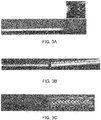
- the stent body may also be formed as described in U.S. Patent Application Publication 2010/0198333 . As shown in FIGs. 1 and 2 , the proximal portion of the stent body may have a different configuration than the distal portion of the stent body. Alternatively, referring to FIGs. 3A-3C , which shows a Cook Medical Zilver stent before and after the thermal processing treatment, the stent body may have a single stent geometry across the proximal and distal portions.
- the stent body may undergo a heat setting treatment to impart a remembered shape thereto (e.g., a radially expanded configuration) and to ensure that the stent body is fully austenitic at body temperature prior to the thermal processing treatment.
- heat setting is carried out at a temperature between about 350°C and about 550°C for a time duration of about 5-60 min.
- the austenite transformation temperatures (A s and A f ) of the stent body are initially less than body temperature (i.e., less than 37°C), and they may also be less than room temperature ( e.g ., about 25°C or less) initially.
- an initial value of A f may lie between-15°C and 25°C.
- the proximal portion of the stent body having initial austenite transformation temperatures less than 37°C is loaded into a first hollow mandrel, and the distal portion of the stent body is loaded over a second hollow mandrel, which includes one or more throughholes in a wall thereof for passage of a cooling fluid.
- the first and second hollow mandrels may be constructed from brass or another thermally conductive material.
- the proximal portion of the stent body is heated to a temperature in the range of from about 300°C to about 550°C, while the distal portion of the stent body is cooled by exposure to a cooling fluid.
- the cooling fluid may be air, water, liquid nitrogen and/or other coolants, and the fluid may be continuously circulated over the distal portion of the stent body.
- the first hollow mandrel and the proximal portion of the stent body contained therein may be immersed in a sand bath. The heating may be carried out for a time duration from about 10 minutes to about 180 minutes, and preferably within the temperature range of from about 350°C to about 450°C.
- the austenite transformation temperatures of the proximal portion of the stent body are raised sufficiently to ensure that the proximal portion does not transform to austenite upon exposure to body temperature.
- a s and A f in the proximal portion of the stent body are raised to values greater than 37°C.
- the shape memory alloy is a two-stage Nitinol alloy exhibiting an R-phase transformation in addition to martensitic and austenitic transformations, then the R-phase transformation temperatures (R s and R f ) in the proximal portion may also be increased above body temperature.
- the proximal portion of the stent body remains martensitic (and thus balloon-expandable).
- the distal portion of the stent body does not experience an increase in the austenite transformation temperatures.
- a s and A f remain below 37°C in the distal portion of the stent body, and thus, when used in the body, the distal portion is fully austenitic and thus self-expanding.
- a stent body having a balloon expandable portion and a self-expanding portion is formed, as shown in FIG. 3C .
- the change in the austenite transformation temperatures in the proximal portion of the stent body as a consequence of the heating in the sand bath may be understood in view of microstructural changes that occur.
- the shape memory alloy is an equiatomic or near-equiatomic nickel-titanium (Ni-Ti) alloy
- the temperature increase may cause nickel-rich precipitates to form in the alloy, producing localised shifts in composition and depleting the Ni-Ti alloy matrix of nickel.
- the overall composition of the alloy remains the same. Due to the localised depletion of nickel from the Ni-Ti alloy matrix, the austenite transformation temperatures (A s and A f ) may increase.
- the A s temperature of the proximal portion of the stent body increases above 37°C, ensuring that the Ni-Ti alloy remains martensitic at body temperature.
- the portion of the stent constrained inside the first hollow mandrel becomes balloon-expandable. Since only the proximal portion of the stent body experiences the heat treatment due to the highly efficient mandrel and the cooling of the distal portion, the initial austenite transformation temperatures in the distal portion do not change substantially. Accordingly, the distal portion of the stent remains superelastic at body temperature.
- the stent body Prior to loading the proximal portion of the stent body into the first hollow mandrel, the stent body may be partially compressed.
- the first hollow mandrel may have an inner diameter slightly larger than an outer diameter of a compressed medical balloon on a balloon catheter, and after fabrication the hybrid prosthesis may be loaded onto the catheter and fully crimped or compressed into a delivery position.
- the first hollow mandrel may include a tapered portion at a distal end thereof, where the tapered portion increases from a constant diameter to a larger diameter in a distal direction.
- the second hollow mandrel may have an outer diameter larger than the inner diameter of the first hollow mandrel, and the outer diameter of the second hollow mandrel may also be larger than the outer diameter of the first hollow mandrel.
- a remaining portion of the first hollow mandrel comprises an untapered portion having the constant diameter along a length of the remaining portion.
- phase transformation temperatures e.g., A s , A f
- DSC measurements may be carried out according to the American Society for Testing and Materials (ASTM) standard F2004-05 entitled “Standard Test Method for Transformation Temperature of Nickel-Titanium Alloys by Thermal Analysis,” which is hereby incorporated by reference.
- ASTM American Society for Testing and Materials
- the DSC method set forth in U.S. Patent Application Publication 2009/0139614 “Method of Characterizing Phase Transformations in Shape Memory Materials," which is hereby incorporated by reference in its entirety, may be employed to identify the phase transformation temperatures.
- the shape memory alloy is advantageously an equiatomic or near-equiatomic nickel-titanium alloy, sometimes referred to as a Nitinol alloy.
- Such alloys include an atomic ratio of nickel to titanium (at.% Ni:at.% Ti) in the range of from 45:55 to 55:45, where an equiatomic ratio is defined as 50:50 (50 at.% Ni:50 at.% Ti).
- a nickel-titanium shape memory alloy (which may also be referred to as a nickel-titanium superelastic alloy) undergoes a reversible phase transformation between a martensitic phase and an austenitic phase that allows it to "remember” and return to a previous shape or configuration.
- compressive strain imparted to a martensitic stent to achieve a low-profile delivery configuration may be substantially recovered during a reverse phase transformation to austenite, such that the stent expands to a "remembered" (e.g ., expanded) configuration at a treatment site in a vessel.
- recoverable strains of about 8-10% may be obtained from superelastic nickel-titanium alloys.
- the forward and reverse phase transformations may be driven by a change in stress (superelastic effect) and/or temperature (shape memory effect).
- Nitinol alloys including, for example, about 51 at.% Ni and about 49 at.% Ti are known to be useful for medical devices which are superelastic at body temperature.
- alloys including 50.6 - 50.8 at. % Ni and 49.2 - 49.4 at.% Ti are considered to be medical grade Nitinol alloys and are suitable for use in the stent body.
- the nickel-titanium alloy may further include one or more additional alloying elements as substitutional elements for the nickel and/or titanium.
- nickel-titanium alloy wire including an inner core of platinum, palladium, or another radiopaque material may also be employed.
- graft materials such as biocompatible polymers
- the graft material may be attached using methods known in the art, such as by stitching using a monofilament or braided suture material.
- An entirety or only a portion of the stent body may be covered or by the graft material, which defines the lumen of the stent graft and which may overlie or underlie the stent body.
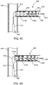
- FIGs. 4A-4E illustrate various stages of deployment of an exemplary hybrid branch vessel prosthesis.
- a main vessel prosthesis 402 is shown already deployed within the main body lumen in a position where a fenestration 414 generally aligns with the opening of a branch vessel.
- the main vessel prosthesis 402 can be deployed in any manner known in the art, including the method described in PCT Patent Application Publication WO 98/53761 , which is hereby incorporated by reference in its entirety.
- the hybrid branch vessel prosthesis 404 includes a hybrid balloon-expandable/self-expanding stent body and attached graft material, as described previously, in a delivery (compressed) configuration over a balloon catheter 470.
- a tubular sheath 472 overlies the self-expanding distal portion of the stent body, and a compressed balloon underlies the proximal portion of the stent body. Retraction of the tubular sheath 472 is used to deploy the self-expanding portion of the stent body, and inflation of the balloon is employed to deploy the balloon-expandable portion of the stent body once the hybrid branch vessel prosthesis 404 is properly positioned within the branch vessel.
- a straight branch vessel is shown in FIGs. 4A-4E ; however, in reality this vessel may be quite tortuous and the hybrid branch vessel prosthesis 404 may therefore undergo flexing and other deformation during insertion and deployment. Details of the deployment are discussed below.
- a delivery device 480 containing the hybrid branch vessel prosthesis 404 in a delivery configuration may be inserted into an artery via a surgical cut-down, or by percutaneous access techniques that are well known in the art.
- a guide wire 474 is introduced into the artery and advanced through the lumen of the main vessel prosthesis 402 and distally through the fenestration 414 into the branch vessel 490, as shown in FIG. 4A , until the prosthesis contained in the delivery device 480 is properly positioned in the branch vessel 490.
- Standard radiographic techniques may be employed to achieve proper positioning by aligning the prosthesis with the fenestration 414.
- the main vessel prosthesis 402 may comprise a positional indicator (not shown) that generally indicates the fenestration 414.
- a radiopaque marker, located on the stent, and/or positional indicator located on the delivery device 480, may be coordinated with the fenestration indicator to ensure proper positioning and orientation of the branch vessel prosthesis 404 with respect to the main vessel prosthesis 402. Once the prosthesis 404 is properly positioned, the delivery device 480 is ready for deployment.
- FIG. 4B shows the delivery device 480 with the prosthesis 404 in a partially-deployed state.
- the tubular sheath 472 has been retracted sufficiently to allow the self-expanding distal portion 410a of the stent body 410 and attached graft material 416 to expand.
- the balloon-expandable portion 410b of the stent body 410 remains undeployed.
- FIG. 4C shows the tubular sheath 472 fully retracted past the proximal portion 410b of the stent body 410 and the introduction of pressurised fluid into the balloon 476 via a balloon inflation lumen, causing the balloon 476 to inflate.
- the balloon-expandable proximal portion 110b of the stent body and attached graft material 416 radially expand so that the side branch prosthesis 404 can fully deploy within the branch vessel 490.
- the balloon 476 may be deflated.
- a second balloon 478 is inflated via a second balloon inflation lumen, causing a flareable end portion 410e of the stent body 410 to flare radially outwards, securing the side branch prosthesis 404 to the main vessel prosthesis 402 at the fenestration 414.
- the graft material 416 of the branch vessel prosthesis 404 may form a fluid seal between the main vessel prosthesis 402 and the branch vessel prosthesis 404.
- the second balloon 478 may be deflated and the delivery device 480 and the guidewire 474 may be withdrawn. If needed, a separate balloon catheter may be inserted to further deform the flareable portion 410e to ensure proper engagement between the main vessel prosthesis 402 and the branch vessel prosthesis 404.
- a fully deployed hybrid branch vessel prosthesis 404 is illustrated in FIG. 4E .
- the hybrid prosthesis 404 may be able to provide higher stiffness near the fenestration and a combination of flexibility and kink-resistance in the branch vessel.
- the above-described method provides a true hybrid balloon-expandable/self-expanding stent made from a monolithic cannula or wire.
- Employing this technology eliminates the need for any welding or joining of two different metals.
- the balloon expandable portion may be designed to provide rigidity and radial strength, while the self-expanding portion offers flexibility and kink resistance.
- the technology eliminates the need to reinforce a bridge stent with another device, a feature that may help to drive down the cost of surgery, and it enables deployment in areas with small seal zones, as the balloon-expandable portion of the device can be flared.
- a hybrid prosthesis for deployment in a body vessel comprising: a tubular stent body comprising a wire comprising a shape memory alloy, the tubular stent body having a self-expanding portion comprising a distal portion of the wire and a balloon-expandable portion comprising a proximal portion of the wire, wherein the shape memory alloy comprises an A f of less than 37°C in the self-expanding portion and an As of greater than 37°C in the balloon-expandable portion.
- an endoluminal hybrid prosthesis system comprising: a main body prosthesis for deployment in a main vessel body lumen, the main body prosthesis comprising a graft material attached to a tubular main stent body so as to form a tubular primary lumen for fluid flow through the main body prosthesis, the graft material comprising a fenestration; a side arm prosthesis for deployment in a side vessel body lumen and attached to the main body prosthesis at the fenestration, the side arm prosthesis comprising: a graft material attached to a tubular secondary stent body so as to form a tubular secondary lumen for fluid flow therethrough, the tubular primary lumen and the tubular secondary lumen being in fluid communication, wherein the tubular secondary stent body comprises a wire comprising a shape memory alloy, the tubular secondary stent body having a self-expanding portion comprising a distal portion of the wire and a balloon-expandable portion comprising
- the distal portion of the wire has a helical configuration comprising bent wire portions alternating with straight wire portions in a helical zigzag pattern about a longitudinal axis of the stent body.
- the proximal portion of the wire has a ring-like configuration including one or more rings centered about a longitudinal axis of the stent body, each of the one or more rings including bent wire portions alternating with straight wire portions in a circumferential zigzag pattern about the longitudinal axis.
- a hybrid prosthesis for deployment in a body vessel comprising: a tubular stent body comprising a wire comprising a shape memory alloy, the tubular stent body having a self-expanding portion comprising a distal portion of the wire and a balloon-expandable portion comprising a proximal portion of the wire, wherein the distal portion of the wire has a helical configuration comprising bent wire first portions alternating with straight wire first portions in a helical zigzag pattern about a longitudinal axis of the stent body, and wherein the proximal portion of the wire has a ring-like configuration including one or more rings centered about a longitudinal axis of the stent body, each of the one or more rings including bent wire second portions alternating with straight wire second portions in a circumferential zigzag pattern about the longitudinal axis.
- the shape memory alloy comprises an A f of less than 37°C in the self-expanding portion and an A s of greater than 37°C in the balloon-expandable portion.
- all of the straight wire first portions have substantially the same length. In other embodiments, every other straight wire first portion has substantially the same length.
- the hybrid prosthesis may be a side arm prosthesis deployable in a branch vessel body lumen.
- the balloon-expandable portion may further comprise a flareable end portion for securing the side arm prosthesis to a main body prosthesis.
- the hybrid prosthesis may further comprise a graft material attached to the stent body and may define a tubular lumen for fluid flow therethrough.
- a method of making a hybrid prosthesis comprising: loading a proximal portion of a stent body comprising a shape memory alloy into a first hollow mandrel, the shape memory alloy having values of A s and A f below body temperature; loading a distal portion of the stent body comprising the shape memory alloy over a second hollow mandrel, the second hollow mandrel comprising one or more throughholes in a wall thereof for passage of a cooling fluid; heating the proximal portion of the stent body to a temperature in the range of from about 300°C to about 550°C; exposing the distal portion of the stent body to a cooling fluid during the heating; and increasing the values of A s and A f in the proximal portion of the stent body to greater than body temperature while the values of A s and A f in the distal portion of the stent body remain below body temperature, thereby forming a hybrid prosthesis including
- the stent body Prior to loading the proximal portion of the stent body into the first hollow mandrel, the stent body may be partially compressed.
- the first hollow mandrel may include a tapered portion at a distal end thereof, the remaining portion of the first hollow mandrel may comprise an untapered portion having a substantially constant diameter along a length of the remaining portion, and the tapered distal portion may increase from the constant diameter to a larger diameter in a direction of the second hollow mandrel.
- the first hollow mandrel may comprise an inner diameter larger than an outer diameter of a compressed medical balloon on a balloon catheter.
- the second hollow mandrel may have an outer diameter larger than an inner diameter of the first hollow mandrel.
Landscapes
- Health & Medical Sciences (AREA)
- Engineering & Computer Science (AREA)
- Biomedical Technology (AREA)
- Chemical & Material Sciences (AREA)
- Transplantation (AREA)
- Cardiology (AREA)
- Heart & Thoracic Surgery (AREA)
- Vascular Medicine (AREA)
- Life Sciences & Earth Sciences (AREA)
- Animal Behavior & Ethology (AREA)
- General Health & Medical Sciences (AREA)
- Public Health (AREA)
- Veterinary Medicine (AREA)
- Oral & Maxillofacial Surgery (AREA)
- Physics & Mathematics (AREA)
- Thermal Sciences (AREA)
- Crystallography & Structural Chemistry (AREA)
- Materials Engineering (AREA)
- Mechanical Engineering (AREA)
- Metallurgy (AREA)
- Organic Chemistry (AREA)
- Media Introduction/Drainage Providing Device (AREA)
- Prostheses (AREA)
Applications Claiming Priority (2)
| Application Number | Priority Date | Filing Date | Title |
|---|---|---|---|
| US13/336,310 US8894701B2 (en) | 2011-12-23 | 2011-12-23 | Hybrid balloon-expandable/self-expanding prosthesis for deployment in a body vessel and method of making |
| EP12275210.8A EP2614795B1 (fr) | 2011-12-23 | 2012-12-18 | Prothèse auto-expansible/expansible sur ballonnet |
Related Parent Applications (2)
| Application Number | Title | Priority Date | Filing Date |
|---|---|---|---|
| EP12275210.8A Division EP2614795B1 (fr) | 2011-12-23 | 2012-12-18 | Prothèse auto-expansible/expansible sur ballonnet |
| EP12275210.8A Division-Into EP2614795B1 (fr) | 2011-12-23 | 2012-12-18 | Prothèse auto-expansible/expansible sur ballonnet |
Publications (2)
| Publication Number | Publication Date |
|---|---|
| EP3150176A1 true EP3150176A1 (fr) | 2017-04-05 |
| EP3150176B1 EP3150176B1 (fr) | 2020-02-26 |
Family
ID=47603145
Family Applications (2)
| Application Number | Title | Priority Date | Filing Date |
|---|---|---|---|
| EP12275210.8A Active EP2614795B1 (fr) | 2011-12-23 | 2012-12-18 | Prothèse auto-expansible/expansible sur ballonnet |
| EP16197983.6A Active EP3150176B1 (fr) | 2011-12-23 | 2012-12-18 | Prothèse auto-expansible/expansible sur ballonnet |
Family Applications Before (1)
| Application Number | Title | Priority Date | Filing Date |
|---|---|---|---|
| EP12275210.8A Active EP2614795B1 (fr) | 2011-12-23 | 2012-12-18 | Prothèse auto-expansible/expansible sur ballonnet |
Country Status (2)
| Country | Link |
|---|---|
| US (2) | US8894701B2 (fr) |
| EP (2) | EP2614795B1 (fr) |
Cited By (1)
| Publication number | Priority date | Publication date | Assignee | Title |
|---|---|---|---|---|
| WO2024148166A1 (fr) * | 2023-01-05 | 2024-07-11 | Merit Medical Systems, Inc. | Appareils et procédés d'endoprothèses hybrides |
Families Citing this family (69)
| Publication number | Priority date | Publication date | Assignee | Title |
|---|---|---|---|---|
| EP1771132B1 (fr) | 2004-02-03 | 2019-03-27 | V-Wave Ltd. | Dispositif et procede de controle de la pression in vivo |
| CN2817768Y (zh) * | 2005-05-24 | 2006-09-20 | 微创医疗器械(上海)有限公司 | 一种覆膜支架的主体支架段及覆膜支架 |
| WO2007083288A2 (fr) | 2006-01-23 | 2007-07-26 | Atria Medical Inc. | Dispositif d’ancre cardiaque |
| US10028747B2 (en) | 2008-05-01 | 2018-07-24 | Aneuclose Llc | Coils with a series of proximally-and-distally-connected loops for occluding a cerebral aneurysm |
| US10716573B2 (en) | 2008-05-01 | 2020-07-21 | Aneuclose | Janjua aneurysm net with a resilient neck-bridging portion for occluding a cerebral aneurysm |
| US12453626B2 (en) | 2009-05-04 | 2025-10-28 | V-Wave Ltd. | Shunt for redistributing atrial blood volume |
| US9034034B2 (en) | 2010-12-22 | 2015-05-19 | V-Wave Ltd. | Devices for reducing left atrial pressure, and methods of making and using same |
| US12186176B2 (en) | 2009-05-04 | 2025-01-07 | V-Wave Ltd. | Shunt for redistributing atrial blood volume |
| EP2427143B1 (fr) | 2009-05-04 | 2017-08-02 | V-Wave Ltd. | Dispositif permettant de réguler la pression à l'intérieur d'une cavité cardiaque |
| US9358140B1 (en) | 2009-11-18 | 2016-06-07 | Aneuclose Llc | Stent with outer member to embolize an aneurysm |
| EP2517671B1 (fr) | 2011-04-28 | 2016-05-11 | Cook Medical Technologies LLC | Appareil destiné à faciliter le déploiement d'une prothèse endoluminale |
| US11135054B2 (en) | 2011-07-28 | 2021-10-05 | V-Wave Ltd. | Interatrial shunts having biodegradable material, and methods of making and using same |
| US9724186B2 (en) | 2012-10-10 | 2017-08-08 | Trivascular, Inc. | Endovascular graft for aneurysms involving major branch vessels |
| ES2800029T3 (es) | 2013-05-21 | 2020-12-23 | V Wave Ltd | Aparato para aplicar dispositivos para reducir la presión atrial izquierda |
| JP6549717B2 (ja) | 2015-01-12 | 2019-07-24 | マイクロベンション インコーポレイテッドMicrovention, Inc. | ステント |
| WO2016163339A1 (fr) * | 2015-04-07 | 2016-10-13 | 二プロ株式会社 | Stent |
| JP6558569B2 (ja) * | 2015-05-21 | 2019-08-14 | ニプロ株式会社 | ステント |
| EP3291773B1 (fr) | 2015-05-07 | 2026-01-07 | The Medical Research, Infrastructure, And Health Services Fund Of The Tel Aviv Medical Center | Shunts interauriculaires temporaires |
| JP6960110B2 (ja) * | 2015-05-21 | 2021-11-05 | ニプロ株式会社 | ステント |
| US20170340460A1 (en) | 2016-05-31 | 2017-11-30 | V-Wave Ltd. | Systems and methods for making encapsulated hourglass shaped stents |
| US10835394B2 (en) | 2016-05-31 | 2020-11-17 | V-Wave, Ltd. | Systems and methods for making encapsulated hourglass shaped stents |
| CN105943199A (zh) * | 2016-05-31 | 2016-09-21 | 李晓东 | 主动脉开窗分支覆膜支架 |
| AU2017343056B2 (en) | 2016-10-10 | 2020-03-12 | Jeng Wei | Blood conduit with stent |
| WO2018076010A1 (fr) * | 2016-10-21 | 2018-04-26 | Confluent Medical Technologies, Inc. | Matériaux ayant des propriétés superélastiques comprenant des procédés de fabrication et de conception associés pour des dispositifs médicaux |
| US11291807B2 (en) | 2017-03-03 | 2022-04-05 | V-Wave Ltd. | Asymmetric shunt for redistributing atrial blood volume |
| US11446168B2 (en) | 2017-04-25 | 2022-09-20 | Cook Medical Technologies Llc | Prosthesis with side branch and method of making the same |
| WO2019018807A1 (fr) | 2017-07-20 | 2019-01-24 | Shifamed Holdings, Llc | Dérivations de glaucome à écoulement réglable et leurs méthodes de fabrication et d'utilisation |
| US11166849B2 (en) | 2017-07-20 | 2021-11-09 | Shifamed Holdings, Llc | Adjustable flow glaucoma shunts and methods for making and using same |
| US10596016B2 (en) | 2017-09-08 | 2020-03-24 | Cook Medical Technologies Llc | Endovascular device configured for sequenced shape memory deployment in a body vessel |
| DE102017123461A1 (de) * | 2017-10-10 | 2019-04-11 | Jotec Gmbh | Expandierbares Gefäßimplantat |
| US11458287B2 (en) | 2018-01-20 | 2022-10-04 | V-Wave Ltd. | Devices with dimensions that can be reduced and increased in vivo, and methods of making and using the same |
| US10898698B1 (en) * | 2020-05-04 | 2021-01-26 | V-Wave Ltd. | Devices with dimensions that can be reduced and increased in vivo, and methods of making and using the same |
| WO2019142152A1 (fr) | 2018-01-20 | 2019-07-25 | V-Wave Ltd. | Dispositifs et procédés pour fournir un passage entre des chambres cardiaques |
| US11291570B2 (en) | 2018-04-27 | 2022-04-05 | Cook Medical Technologies Llc | Hybrid stent and delivery system |
| WO2020142613A1 (fr) | 2019-01-04 | 2020-07-09 | Shifamed Holdings, Llc | Systèmes de recharge interne et procédés d'utilisation |
| WO2020150663A1 (fr) | 2019-01-18 | 2020-07-23 | Shifamed Holdings, Llc | Dérivations de glaucome à écoulement réglable et leurs méthodes de fabrication et d'utilisation |
| US12521225B2 (en) | 2019-01-31 | 2026-01-13 | Becton, Dickinson And Company | Mixed-frame intraluminal prosthesis and methods thereof |
| US12226602B2 (en) | 2019-04-03 | 2025-02-18 | V-Wave Ltd. | Systems for delivering implantable devices across an atrial septum |
| US11612385B2 (en) | 2019-04-03 | 2023-03-28 | V-Wave Ltd. | Systems and methods for delivering implantable devices across an atrial septum |
| RU2720745C1 (ru) * | 2019-05-13 | 2020-05-13 | Общество с ограниченной ответственностью "Энкора" (ООО "Энкора") | Комбинированный гибридный протез с бесшовными соединениями для "открытых" хирургических вмешательств при расслаивающих аневризмах грудной аорты и способ его имплантации |
| EP3972499A1 (fr) | 2019-05-20 | 2022-03-30 | V-Wave Ltd. | Systèmes et procédés de création de dérivation interauriculaire |
| EP3982882A4 (fr) * | 2019-06-17 | 2023-07-05 | The Foundry, LLC | Dispositif hybride expansible |
| US12533500B2 (en) | 2019-06-18 | 2026-01-27 | Shifamed Holdings, Llc | Adjustable interatrial shunts and associated systems and methods |
| US12551268B2 (en) | 2019-07-08 | 2026-02-17 | Shifamed Holdings, Llc | Minimally invasive bleb formation devices and methods for using such devices |
| WO2021050589A1 (fr) | 2019-09-09 | 2021-03-18 | Shifamed Holdings, Llc | Shunts ajustables et systèmes et méthodes associés |
| GB2587013A (en) | 2019-09-13 | 2021-03-17 | Tevar Pty Ltd | Inflatable dilatation device |
| JP7614193B2 (ja) | 2019-10-10 | 2025-01-15 | シファメド・ホールディングス・エルエルシー | 流量調整可能な緑内障用シャントならびに関連システム及び方法 |
| US11253685B2 (en) | 2019-12-05 | 2022-02-22 | Shifamed Holdings, Llc | Implantable shunt systems and methods |
| WO2021151007A1 (fr) | 2020-01-23 | 2021-07-29 | Shifamed Holdings, Llc | Shunts de glaucome à débit réglable et systèmes et méthodes associés |
| WO2021163566A1 (fr) | 2020-02-14 | 2021-08-19 | Shifamed Holdings, Llc | Systèmes de dérivation avec ensembles de régulation de débit par rotation, et systèmes et méthodes associés |
| EP4106695A4 (fr) | 2020-02-18 | 2024-03-20 | Shifamed Holdings, LLC | Shunts de glaucome à écoulement réglable ayant des éléments de commande d'écoulement disposés de manière non linéaire, et systèmes et procédés associés |
| CN111281600A (zh) * | 2020-02-27 | 2020-06-16 | 苏州特普新智能科技有限公司 | Tips用支架 |
| US11766355B2 (en) | 2020-03-19 | 2023-09-26 | Shifamed Holdings, Llc | Intraocular shunts with low-profile actuation elements and associated systems and methods |
| EP4135640B1 (fr) | 2020-04-16 | 2025-12-24 | Shifamed Holdings, LLC | Dispositifs réglables de traitement de glaucome, ainsi que systèmes associés |
| US12213817B2 (en) | 2020-04-23 | 2025-02-04 | Shifamed Holdings, Llc | Systems and methods for radiographic monitoring of shunts |
| US11622695B1 (en) | 2020-04-23 | 2023-04-11 | Shifamed Holdings, Llc | Intracardiac sensors with switchable configurations and associated systems and methods |
| US12440656B2 (en) | 2020-04-23 | 2025-10-14 | Shifamed Holdings, Llc | Power management for interatrial shunts and associated systems and methods |
| US12599756B2 (en) | 2020-05-04 | 2026-04-14 | V-Wave Ltd. | Devices with dimensions that can be reduced and increased In Vivo |
| CN116367795A (zh) | 2020-08-25 | 2023-06-30 | 施菲姆德控股有限责任公司 | 可调节的心房间分流器及相关联的系统和方法 |
| US12544010B2 (en) | 2020-10-28 | 2026-02-10 | Shifamed Holdings, Llc | Systems and methods for electrical monitoring of implantable devices |
| RU2754769C1 (ru) * | 2020-11-03 | 2021-09-07 | федеральное государственное бюджетное учреждение «Национальный медицинский исследовательский центр имени академика Е.Н. Мешалкина» Министерства здравоохранения Российской Федерации (ФГБУ «НМИЦ им. ак. Е.Н. Мешалкина» Минздрава России) | Комбинированный гибридный протез с бесшовными соединениями для протезирования грудной аорты и ее ветвей (варианты) и способ его имплантации (варианты) |
| US11857197B2 (en) | 2020-11-12 | 2024-01-02 | Shifamed Holdings, Llc | Adjustable implantable devices and associated methods |
| US11234702B1 (en) | 2020-11-13 | 2022-02-01 | V-Wave Ltd. | Interatrial shunt having physiologic sensor |
| US11865283B2 (en) | 2021-01-22 | 2024-01-09 | Shifamed Holdings, Llc | Adjustable shunting systems with plate assemblies, and associated systems and methods |
| EP4304700A4 (fr) | 2021-03-09 | 2025-03-19 | Shifamed Holdings, LLC | Actionneurs à mémoire de forme pour systèmes de dérivation réglables et systèmes et procédés associés |
| CN114948363B (zh) * | 2022-04-11 | 2023-04-18 | 上海玮琅医疗科技有限公司 | 一种y型分叉的上腔静脉支架 |
| EP4486225A1 (fr) | 2022-04-14 | 2025-01-08 | V-Wave Ltd. | Shunt interauriculaire à région de col étendue |
| CN116035787A (zh) * | 2022-12-26 | 2023-05-02 | 应脉医疗科技(上海)有限公司 | 支架及支架制作方法 |
| US12296122B2 (en) | 2023-10-18 | 2025-05-13 | V-Wave Ltd. | Hybrid devices with dimensions that can be adjusted in vivo and methods of manufacturing thereof |
Citations (6)
| Publication number | Priority date | Publication date | Assignee | Title |
|---|---|---|---|---|
| EP1138280A2 (fr) * | 2000-03-31 | 2001-10-04 | Cordis Corporation | Stent aux extrémités auto-déployables |
| CA2468670A1 (fr) * | 2001-12-05 | 2003-06-19 | Boston Scientific Limited | Stent a auto-dilatation et dilatation du ballonnet combinee |
| US20030195609A1 (en) * | 2002-04-10 | 2003-10-16 | Scimed Life Systems, Inc. | Hybrid stent |
| US20050004647A1 (en) * | 2003-07-03 | 2005-01-06 | William Cook Europe Aps | Hybrid stent apparatus |
| US6890350B1 (en) * | 1999-07-28 | 2005-05-10 | Scimed Life Systems, Inc. | Combination self-expandable, balloon-expandable endoluminal device |
| US20070005126A1 (en) * | 2005-06-30 | 2007-01-04 | Boston Scientific Scimed, Inc. | Hybrid stent |
Family Cites Families (25)
| Publication number | Priority date | Publication date | Assignee | Title |
|---|---|---|---|---|
| US4484955A (en) | 1983-12-12 | 1984-11-27 | Hochstein Peter A | Shape memory material and method of treating same |
| ATE345750T1 (de) * | 1993-03-11 | 2006-12-15 | Medinol Ltd | Stent |
| ES2126896T3 (es) * | 1994-05-19 | 1999-04-01 | Scimed Life Systems Inc | Dispositivos mejorados de soporte de tejidos biologicos. |
| AUPO700897A0 (en) | 1997-05-26 | 1997-06-19 | William A Cook Australia Pty Ltd | A method and means of deploying a graft |
| US6485507B1 (en) | 1999-07-28 | 2002-11-26 | Scimed Life Systems | Multi-property nitinol by heat treatment |
| US7632303B1 (en) | 2000-06-07 | 2009-12-15 | Advanced Cardiovascular Systems, Inc. | Variable stiffness medical devices |
| US6652576B1 (en) | 2000-06-07 | 2003-11-25 | Advanced Cardiovascular Systems, Inc. | Variable stiffness stent |
| US6626937B1 (en) | 2000-11-14 | 2003-09-30 | Advanced Cardiovascular Systems, Inc. | Austenitic nitinol medical devices |
| US7175655B1 (en) * | 2001-09-17 | 2007-02-13 | Endovascular Technologies, Inc. | Avoiding stress-induced martensitic transformation in nickel titanium alloys used in medical devices |
| ATE380001T1 (de) * | 2001-10-22 | 2007-12-15 | Terumo Corp | Stent und verfahren zu dessen herstellung |
| US6923829B2 (en) | 2002-11-25 | 2005-08-02 | Advanced Bio Prosthetic Surfaces, Ltd. | Implantable expandable medical devices having regions of differential mechanical properties and methods of making same |
| US9125733B2 (en) * | 2003-01-14 | 2015-09-08 | The Cleveland Clinic Foundation | Branched vessel endoluminal device |
| WO2005034807A1 (fr) * | 2003-10-10 | 2005-04-21 | William A. Cook Australia Pty. Ltd | Extenseur-greffon composite |
| US8747453B2 (en) * | 2008-02-18 | 2014-06-10 | Aga Medical Corporation | Stent/stent graft for reinforcement of vascular abnormalities and associated method |
| US20060074403A1 (en) | 2004-09-29 | 2006-04-06 | Nasser Rafiee | Curved catheter comprising a solid-walled metal tube with varying stiffness |
| WO2007095283A2 (fr) | 2006-02-13 | 2007-08-23 | Willam A. Cook Australia Pty. Ltd. | Construction d'une endoprothese a branche laterale |
| US20070219618A1 (en) * | 2006-03-17 | 2007-09-20 | Cully Edward H | Endoprosthesis having multiple helically wound flexible framework elements |
| WO2007146021A2 (fr) | 2006-06-06 | 2007-12-21 | Cook Incorporated | Stent avec zone résistant à l'écrasement |
| AU2007293025B2 (en) * | 2006-09-06 | 2011-06-30 | Cook Medical Technologies Llc | Nickel-titanium alloy including a rare earth element |
| US9107741B2 (en) | 2007-11-01 | 2015-08-18 | Cook Medical Technologies Llc | Flexible stent graft |
| US8088233B2 (en) | 2007-12-04 | 2012-01-03 | Cook Medical Technologies Llc | Method of characterizing phase transformations in shape memory materials |
| US8641753B2 (en) | 2009-01-31 | 2014-02-04 | Cook Medical Technologies Llc | Preform for and an endoluminal prosthesis |
| EP2408397B1 (fr) * | 2009-03-16 | 2014-09-24 | Cook Medical Technologies LLC | Stent hybride et procédé de fabrication d'un tel stent |
| GB2476479B (en) * | 2009-12-22 | 2012-06-20 | Cook Medical Technologies Llc | Implantable device |
| EP2563290B1 (fr) * | 2010-04-30 | 2020-09-02 | Boston Scientific Scimed, Inc. | Appareil et procédé de fabrication d'une endoprothèse à fil unique |
-
2011
- 2011-12-23 US US13/336,310 patent/US8894701B2/en active Active
-
2012
- 2012-12-18 EP EP12275210.8A patent/EP2614795B1/fr active Active
- 2012-12-18 EP EP16197983.6A patent/EP3150176B1/fr active Active
-
2014
- 2014-10-22 US US14/520,796 patent/US9675481B2/en active Active
Patent Citations (6)
| Publication number | Priority date | Publication date | Assignee | Title |
|---|---|---|---|---|
| US6890350B1 (en) * | 1999-07-28 | 2005-05-10 | Scimed Life Systems, Inc. | Combination self-expandable, balloon-expandable endoluminal device |
| EP1138280A2 (fr) * | 2000-03-31 | 2001-10-04 | Cordis Corporation | Stent aux extrémités auto-déployables |
| CA2468670A1 (fr) * | 2001-12-05 | 2003-06-19 | Boston Scientific Limited | Stent a auto-dilatation et dilatation du ballonnet combinee |
| US20030195609A1 (en) * | 2002-04-10 | 2003-10-16 | Scimed Life Systems, Inc. | Hybrid stent |
| US20050004647A1 (en) * | 2003-07-03 | 2005-01-06 | William Cook Europe Aps | Hybrid stent apparatus |
| US20070005126A1 (en) * | 2005-06-30 | 2007-01-04 | Boston Scientific Scimed, Inc. | Hybrid stent |
Cited By (1)
| Publication number | Priority date | Publication date | Assignee | Title |
|---|---|---|---|---|
| WO2024148166A1 (fr) * | 2023-01-05 | 2024-07-11 | Merit Medical Systems, Inc. | Appareils et procédés d'endoprothèses hybrides |
Also Published As
| Publication number | Publication date |
|---|---|
| EP2614795A2 (fr) | 2013-07-17 |
| EP3150176B1 (fr) | 2020-02-26 |
| US20150034217A1 (en) | 2015-02-05 |
| US9675481B2 (en) | 2017-06-13 |
| EP2614795A3 (fr) | 2013-11-06 |
| US8894701B2 (en) | 2014-11-25 |
| EP2614795B1 (fr) | 2017-02-15 |
| US20130166010A1 (en) | 2013-06-27 |
Similar Documents
| Publication | Publication Date | Title |
|---|---|---|
| EP3150176B1 (fr) | Prothèse auto-expansible/expansible sur ballonnet | |
| US7611530B2 (en) | Expandable stent having removable slat members | |
| EP2001403B1 (fr) | Stent intravasculaire installable pour le renforcement d'un anévrisme aortique abdominal | |
| JP5087397B2 (ja) | 長さ方向に支持されていない部分を有する血管内ステント−移植片を送出すための装置および方法 | |
| US9060853B2 (en) | Stent and stent-graft designs | |
| JP5643806B2 (ja) | 巻き上げ式密封アセンブリを備えた分岐血管プロテーゼ | |
| EP2263618B1 (fr) | Fixation d'endoprothèse et mécanisme de déploiement | |
| JP5629871B2 (ja) | 移植片あるいは移植片システムを配置する装置および方法 | |
| US9629734B2 (en) | Implant having high fatigue resistance, delivery system, and method of use | |
| AU2012203620B2 (en) | Helical Stent | |
| US20070055299A1 (en) | Temporary stents and stent-grafts | |
| US20140135899A1 (en) | Asymmetric stent apparatus and method | |
| JPH11509767A (ja) | 二叉の血管内ステント並びにその設置のための方法及び装置 | |
| JPH11332998A (ja) | 超弾性の関節部分を有する多層形ステント | |
| US20070219622A1 (en) | Stent-graft structure having one or more stent pockets | |
| JP2001333987A (ja) | 一時留置型ステントグラフト | |
| EP2529704B1 (fr) | Système de pose de prothèse | |
| EP3324883B1 (fr) | Formation d'alvéoles de greffon pour améliorer le profil de sertissage et réduire des forces de mise en place |
Legal Events
| Date | Code | Title | Description |
|---|---|---|---|
| PUAI | Public reference made under article 153(3) epc to a published international application that has entered the european phase |
Free format text: ORIGINAL CODE: 0009012 |
|
| STAA | Information on the status of an ep patent application or granted ep patent |
Free format text: STATUS: THE APPLICATION HAS BEEN PUBLISHED |
|
| AC | Divisional application: reference to earlier application |
Ref document number: 2614795 Country of ref document: EP Kind code of ref document: P |
|
| AK | Designated contracting states |
Kind code of ref document: A1 Designated state(s): AL AT BE BG CH CY CZ DE DK EE ES FI FR GB GR HR HU IE IS IT LI LT LU LV MC MK MT NL NO PL PT RO RS SE SI SK SM TR |
|
| STAA | Information on the status of an ep patent application or granted ep patent |
Free format text: STATUS: REQUEST FOR EXAMINATION WAS MADE |
|
| 17P | Request for examination filed |
Effective date: 20170821 |
|
| RBV | Designated contracting states (corrected) |
Designated state(s): AL AT BE BG CH CY CZ DE DK EE ES FI FR GB GR HR HU IE IS IT LI LT LU LV MC MK MT NL NO PL PT RO RS SE SI SK SM TR |
|
| GRAP | Despatch of communication of intention to grant a patent |
Free format text: ORIGINAL CODE: EPIDOSNIGR1 |
|
| STAA | Information on the status of an ep patent application or granted ep patent |
Free format text: STATUS: GRANT OF PATENT IS INTENDED |
|
| INTG | Intention to grant announced |
Effective date: 20190925 |
|
| GRAS | Grant fee paid |
Free format text: ORIGINAL CODE: EPIDOSNIGR3 |
|
| GRAA | (expected) grant |
Free format text: ORIGINAL CODE: 0009210 |
|
| STAA | Information on the status of an ep patent application or granted ep patent |
Free format text: STATUS: THE PATENT HAS BEEN GRANTED |
|
| AC | Divisional application: reference to earlier application |
Ref document number: 2614795 Country of ref document: EP Kind code of ref document: P |
|
| AK | Designated contracting states |
Kind code of ref document: B1 Designated state(s): AL AT BE BG CH CY CZ DE DK EE ES FI FR GB GR HR HU IE IS IT LI LT LU LV MC MK MT NL NO PL PT RO RS SE SI SK SM TR |
|
| REG | Reference to a national code |
Ref country code: GB Ref legal event code: FG4D |
|
| REG | Reference to a national code |
Ref country code: CH Ref legal event code: EP |
|
| REG | Reference to a national code |
Ref country code: AT Ref legal event code: REF Ref document number: 1236747 Country of ref document: AT Kind code of ref document: T Effective date: 20200315 |
|
| REG | Reference to a national code |
Ref country code: IE Ref legal event code: FG4D |
|
| REG | Reference to a national code |
Ref country code: DE Ref legal event code: R096 Ref document number: 602012068165 Country of ref document: DE |
|
| PG25 | Lapsed in a contracting state [announced via postgrant information from national office to epo] |
Ref country code: FI Free format text: LAPSE BECAUSE OF FAILURE TO SUBMIT A TRANSLATION OF THE DESCRIPTION OR TO PAY THE FEE WITHIN THE PRESCRIBED TIME-LIMIT Effective date: 20200226 Ref country code: RS Free format text: LAPSE BECAUSE OF FAILURE TO SUBMIT A TRANSLATION OF THE DESCRIPTION OR TO PAY THE FEE WITHIN THE PRESCRIBED TIME-LIMIT Effective date: 20200226 Ref country code: NO Free format text: LAPSE BECAUSE OF FAILURE TO SUBMIT A TRANSLATION OF THE DESCRIPTION OR TO PAY THE FEE WITHIN THE PRESCRIBED TIME-LIMIT Effective date: 20200526 |
|
| REG | Reference to a national code |
Ref country code: NL Ref legal event code: MP Effective date: 20200226 |
|
| REG | Reference to a national code |
Ref country code: LT Ref legal event code: MG4D |
|
| PG25 | Lapsed in a contracting state [announced via postgrant information from national office to epo] |
Ref country code: SE Free format text: LAPSE BECAUSE OF FAILURE TO SUBMIT A TRANSLATION OF THE DESCRIPTION OR TO PAY THE FEE WITHIN THE PRESCRIBED TIME-LIMIT Effective date: 20200226 Ref country code: LV Free format text: LAPSE BECAUSE OF FAILURE TO SUBMIT A TRANSLATION OF THE DESCRIPTION OR TO PAY THE FEE WITHIN THE PRESCRIBED TIME-LIMIT Effective date: 20200226 Ref country code: BG Free format text: LAPSE BECAUSE OF FAILURE TO SUBMIT A TRANSLATION OF THE DESCRIPTION OR TO PAY THE FEE WITHIN THE PRESCRIBED TIME-LIMIT Effective date: 20200526 Ref country code: IS Free format text: LAPSE BECAUSE OF FAILURE TO SUBMIT A TRANSLATION OF THE DESCRIPTION OR TO PAY THE FEE WITHIN THE PRESCRIBED TIME-LIMIT Effective date: 20200626 Ref country code: GR Free format text: LAPSE BECAUSE OF FAILURE TO SUBMIT A TRANSLATION OF THE DESCRIPTION OR TO PAY THE FEE WITHIN THE PRESCRIBED TIME-LIMIT Effective date: 20200527 Ref country code: HR Free format text: LAPSE BECAUSE OF FAILURE TO SUBMIT A TRANSLATION OF THE DESCRIPTION OR TO PAY THE FEE WITHIN THE PRESCRIBED TIME-LIMIT Effective date: 20200226 |
|
| PG25 | Lapsed in a contracting state [announced via postgrant information from national office to epo] |
Ref country code: NL Free format text: LAPSE BECAUSE OF FAILURE TO SUBMIT A TRANSLATION OF THE DESCRIPTION OR TO PAY THE FEE WITHIN THE PRESCRIBED TIME-LIMIT Effective date: 20200226 |
|
| PG25 | Lapsed in a contracting state [announced via postgrant information from national office to epo] |
Ref country code: SK Free format text: LAPSE BECAUSE OF FAILURE TO SUBMIT A TRANSLATION OF THE DESCRIPTION OR TO PAY THE FEE WITHIN THE PRESCRIBED TIME-LIMIT Effective date: 20200226 Ref country code: LT Free format text: LAPSE BECAUSE OF FAILURE TO SUBMIT A TRANSLATION OF THE DESCRIPTION OR TO PAY THE FEE WITHIN THE PRESCRIBED TIME-LIMIT Effective date: 20200226 Ref country code: DK Free format text: LAPSE BECAUSE OF FAILURE TO SUBMIT A TRANSLATION OF THE DESCRIPTION OR TO PAY THE FEE WITHIN THE PRESCRIBED TIME-LIMIT Effective date: 20200226 Ref country code: PT Free format text: LAPSE BECAUSE OF FAILURE TO SUBMIT A TRANSLATION OF THE DESCRIPTION OR TO PAY THE FEE WITHIN THE PRESCRIBED TIME-LIMIT Effective date: 20200719 Ref country code: SM Free format text: LAPSE BECAUSE OF FAILURE TO SUBMIT A TRANSLATION OF THE DESCRIPTION OR TO PAY THE FEE WITHIN THE PRESCRIBED TIME-LIMIT Effective date: 20200226 Ref country code: EE Free format text: LAPSE BECAUSE OF FAILURE TO SUBMIT A TRANSLATION OF THE DESCRIPTION OR TO PAY THE FEE WITHIN THE PRESCRIBED TIME-LIMIT Effective date: 20200226 Ref country code: RO Free format text: LAPSE BECAUSE OF FAILURE TO SUBMIT A TRANSLATION OF THE DESCRIPTION OR TO PAY THE FEE WITHIN THE PRESCRIBED TIME-LIMIT Effective date: 20200226 Ref country code: ES Free format text: LAPSE BECAUSE OF FAILURE TO SUBMIT A TRANSLATION OF THE DESCRIPTION OR TO PAY THE FEE WITHIN THE PRESCRIBED TIME-LIMIT Effective date: 20200226 Ref country code: CZ Free format text: LAPSE BECAUSE OF FAILURE TO SUBMIT A TRANSLATION OF THE DESCRIPTION OR TO PAY THE FEE WITHIN THE PRESCRIBED TIME-LIMIT Effective date: 20200226 |
|
| REG | Reference to a national code |
Ref country code: AT Ref legal event code: MK05 Ref document number: 1236747 Country of ref document: AT Kind code of ref document: T Effective date: 20200226 |
|
| REG | Reference to a national code |
Ref country code: DE Ref legal event code: R097 Ref document number: 602012068165 Country of ref document: DE |
|
| PLBE | No opposition filed within time limit |
Free format text: ORIGINAL CODE: 0009261 |
|
| STAA | Information on the status of an ep patent application or granted ep patent |
Free format text: STATUS: NO OPPOSITION FILED WITHIN TIME LIMIT |
|
| PG25 | Lapsed in a contracting state [announced via postgrant information from national office to epo] |
Ref country code: IT Free format text: LAPSE BECAUSE OF FAILURE TO SUBMIT A TRANSLATION OF THE DESCRIPTION OR TO PAY THE FEE WITHIN THE PRESCRIBED TIME-LIMIT Effective date: 20200226 Ref country code: AT Free format text: LAPSE BECAUSE OF FAILURE TO SUBMIT A TRANSLATION OF THE DESCRIPTION OR TO PAY THE FEE WITHIN THE PRESCRIBED TIME-LIMIT Effective date: 20200226 |
|
| 26N | No opposition filed |
Effective date: 20201127 |
|
| PG25 | Lapsed in a contracting state [announced via postgrant information from national office to epo] |
Ref country code: SI Free format text: LAPSE BECAUSE OF FAILURE TO SUBMIT A TRANSLATION OF THE DESCRIPTION OR TO PAY THE FEE WITHIN THE PRESCRIBED TIME-LIMIT Effective date: 20200226 Ref country code: PL Free format text: LAPSE BECAUSE OF FAILURE TO SUBMIT A TRANSLATION OF THE DESCRIPTION OR TO PAY THE FEE WITHIN THE PRESCRIBED TIME-LIMIT Effective date: 20200226 |
|
| REG | Reference to a national code |
Ref country code: CH Ref legal event code: PL |
|
| PG25 | Lapsed in a contracting state [announced via postgrant information from national office to epo] |
Ref country code: MC Free format text: LAPSE BECAUSE OF FAILURE TO SUBMIT A TRANSLATION OF THE DESCRIPTION OR TO PAY THE FEE WITHIN THE PRESCRIBED TIME-LIMIT Effective date: 20200226 |
|
| REG | Reference to a national code |
Ref country code: BE Ref legal event code: MM Effective date: 20201231 |
|
| PG25 | Lapsed in a contracting state [announced via postgrant information from national office to epo] |
Ref country code: LU Free format text: LAPSE BECAUSE OF NON-PAYMENT OF DUE FEES Effective date: 20201218 Ref country code: FR Free format text: LAPSE BECAUSE OF NON-PAYMENT OF DUE FEES Effective date: 20201231 |
|
| PG25 | Lapsed in a contracting state [announced via postgrant information from national office to epo] |
Ref country code: CH Free format text: LAPSE BECAUSE OF NON-PAYMENT OF DUE FEES Effective date: 20201231 Ref country code: LI Free format text: LAPSE BECAUSE OF NON-PAYMENT OF DUE FEES Effective date: 20201231 |
|
| PG25 | Lapsed in a contracting state [announced via postgrant information from national office to epo] |
Ref country code: TR Free format text: LAPSE BECAUSE OF FAILURE TO SUBMIT A TRANSLATION OF THE DESCRIPTION OR TO PAY THE FEE WITHIN THE PRESCRIBED TIME-LIMIT Effective date: 20200226 Ref country code: MT Free format text: LAPSE BECAUSE OF FAILURE TO SUBMIT A TRANSLATION OF THE DESCRIPTION OR TO PAY THE FEE WITHIN THE PRESCRIBED TIME-LIMIT Effective date: 20200226 Ref country code: CY Free format text: LAPSE BECAUSE OF FAILURE TO SUBMIT A TRANSLATION OF THE DESCRIPTION OR TO PAY THE FEE WITHIN THE PRESCRIBED TIME-LIMIT Effective date: 20200226 |
|
| PG25 | Lapsed in a contracting state [announced via postgrant information from national office to epo] |
Ref country code: MK Free format text: LAPSE BECAUSE OF FAILURE TO SUBMIT A TRANSLATION OF THE DESCRIPTION OR TO PAY THE FEE WITHIN THE PRESCRIBED TIME-LIMIT Effective date: 20200226 Ref country code: AL Free format text: LAPSE BECAUSE OF FAILURE TO SUBMIT A TRANSLATION OF THE DESCRIPTION OR TO PAY THE FEE WITHIN THE PRESCRIBED TIME-LIMIT Effective date: 20200226 |
|
| PG25 | Lapsed in a contracting state [announced via postgrant information from national office to epo] |
Ref country code: BE Free format text: LAPSE BECAUSE OF NON-PAYMENT OF DUE FEES Effective date: 20201231 |
|
| P01 | Opt-out of the competence of the unified patent court (upc) registered |
Effective date: 20230602 |
|
| PGFP | Annual fee paid to national office [announced via postgrant information from national office to epo] |
Ref country code: GB Payment date: 20251223 Year of fee payment: 14 |
|
| PGFP | Annual fee paid to national office [announced via postgrant information from national office to epo] |
Ref country code: IE Payment date: 20251218 Year of fee payment: 14 |
|
| PGFP | Annual fee paid to national office [announced via postgrant information from national office to epo] |
Ref country code: DE Payment date: 20251229 Year of fee payment: 14 |