EP3150338A1 - Outillage électrique, moteur et système d'entraînement moteur - Google Patents
Outillage électrique, moteur et système d'entraînement moteur Download PDFInfo
- Publication number
- EP3150338A1 EP3150338A1 EP16188403.6A EP16188403A EP3150338A1 EP 3150338 A1 EP3150338 A1 EP 3150338A1 EP 16188403 A EP16188403 A EP 16188403A EP 3150338 A1 EP3150338 A1 EP 3150338A1
- Authority
- EP
- European Patent Office
- Prior art keywords
- switch
- electronic switch
- motor
- motor drive
- coupled
- Prior art date
- Legal status (The legal status is an assumption and is not a legal conclusion. Google has not performed a legal analysis and makes no representation as to the accuracy of the status listed.)
- Granted
Links
Images

Classifications
-
- H—ELECTRICITY
- H02—GENERATION; CONVERSION OR DISTRIBUTION OF ELECTRIC POWER
- H02P—CONTROL OR REGULATION OF ELECTRIC MOTORS, ELECTRIC GENERATORS OR DYNAMO-ELECTRIC CONVERTERS; CONTROLLING TRANSFORMERS, REACTORS OR CHOKE COILS
- H02P1/00—Arrangements for starting electric motors or dynamo-electric converters
- H02P1/02—Details of starting control
- H02P1/022—Security devices, e.g. correct phase sequencing
- H02P1/026—Means for delayed starting
-
- H—ELECTRICITY
- H02—GENERATION; CONVERSION OR DISTRIBUTION OF ELECTRIC POWER
- H02P—CONTROL OR REGULATION OF ELECTRIC MOTORS, ELECTRIC GENERATORS OR DYNAMO-ELECTRIC CONVERTERS; CONTROLLING TRANSFORMERS, REACTORS OR CHOKE COILS
- H02P3/00—Arrangements for stopping or slowing electric motors, generators, or dynamo-electric converters
- H02P3/06—Arrangements for stopping or slowing electric motors, generators, or dynamo-electric converters for stopping or slowing an individual dynamo-electric motor or dynamo-electric converter
- H02P3/18—Arrangements for stopping or slowing electric motors, generators, or dynamo-electric converters for stopping or slowing an individual dynamo-electric motor or dynamo-electric converter for stopping or slowing an AC motor
-
- B—PERFORMING OPERATIONS; TRANSPORTING
- B25—HAND TOOLS; PORTABLE POWER-DRIVEN TOOLS; MANIPULATORS
- B25F—COMBINATION OR MULTI-PURPOSE TOOLS NOT OTHERWISE PROVIDED FOR; DETAILS OR COMPONENTS OF PORTABLE POWER-DRIVEN TOOLS NOT PARTICULARLY RELATED TO THE OPERATIONS PERFORMED AND NOT OTHERWISE PROVIDED FOR
- B25F5/00—Details or components of portable power-driven tools not particularly related to the operations performed and not otherwise provided for
-
- H—ELECTRICITY
- H02—GENERATION; CONVERSION OR DISTRIBUTION OF ELECTRIC POWER
- H02P—CONTROL OR REGULATION OF ELECTRIC MOTORS, ELECTRIC GENERATORS OR DYNAMO-ELECTRIC CONVERTERS; CONTROLLING TRANSFORMERS, REACTORS OR CHOKE COILS
- H02P27/00—Arrangements or methods for the control of AC motors characterised by the kind of supply voltage
- H02P27/04—Arrangements or methods for the control of AC motors characterised by the kind of supply voltage using variable-frequency supply voltage, e.g. inverter or converter supply voltage
- H02P27/06—Arrangements or methods for the control of AC motors characterised by the kind of supply voltage using variable-frequency supply voltage, e.g. inverter or converter supply voltage using DC to AC converters or inverters
Definitions
- the present disclosure relates to an electric tool, and in particular to a motor drive system applicable to the electric tool.
- an electric saw is used to perform tasks such as forest harvesting, bucking, branching and wood cutting
- an electric drill is used to drill holes
- an electric screwdriver is used to tighten or remove screws
- a hand mill is used to perform edging, trimming and polishing on glass and resin. Electric tools are easy to operate and are laborsaving.
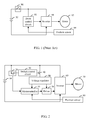
- FIG. 1 shows a drive circuit for an electric tool in the conventional technology.
- a trigger switch 90 is needed in the electric tool in the conventional technology to control the electric tool to operate or not.
- the trigger switch 90 is connected between a power supply 92 and an inverter 94 of the electric tool.
- a drive control circuit 93 outputs a drive signal based on a position of a magnetic field of a rotor detected by a position sensor 99, to control the inverter 94 to convert electrical power of the power supply 92 into alternating current power which is supplied to a motor 95, so that the motor 95 drives a working head of the electric tool to operate.
- the trigger switch 90 Since the trigger switch 90 is connected between the power supply 92 and the inverter 94 of the electric tool, the trigger switch 90 is required to have a very high rated current. For example, in an electric drill, the rated current may be up to about 10 amperes. In practice, a trigger switch that can withstand a high current is expensive, which increases the cost of the electric tool.
- An electric tool, a motor assembly and a motor drive system for the electric tool are provided according to the present disclosure to reduce the cost.
- a motor drive system is provided according to an embodiment in the present disclosure.
- the motor drive system includes:
- the switch control circuit comprises a delay unit connected between the electronic switch and the trigger switch and configured to delay to turn off the electronic switch for a delay time since the trigger switch is turned off.
- the motor drive control circuit comprises a microcontroller configured to detect the state of the trigger switch and control the motor to brake during the delay time.
- the electronic switch is a first electronic switch
- the switch control circuit further comprises a second electronic switch, and a diode
- a control terminal of the second electronic switch is coupled to a cathode of the diode through the delay unit, an anode of the diode is coupled to the power supply through the trigger switch
- a first terminal of the second electronic switch is coupled to a control terminal of the first electronic switch through a first resistor
- the control terminal of the first electronic switch is coupled to the power supply through a second resistor
- a first terminal of the first electronic switch is coupled to the power supply
- a second terminal of the first electronic switch is coupled to the motor drive control circuit
- the control terminal of the second electronic switch is coupled to the second terminal of the second electronic switch through a third resistor.
- the delay unit comprises a capacitor and a fourth resistor, the fourth resistor is connected between the cathode of the diode and the control terminal of the second electronic switch, and the capacitor is connected between the cathode of the diode and ground.
- a rated current of the trigger switch is lower than 100 milliamperes.
- the motor drive control circuit comprises a microcontroller which is configured to detect an operation of the trigger switch and control, after learning that the trigger switch is turned off, the motor to perform a braking operation and is configured to send, after the braking operation of the motor is completed, a control signal to the switch control circuit to turn off the electronic switch.
- a microcontroller which is configured to detect an operation of the trigger switch and control, after learning that the trigger switch is turned off, the motor to perform a braking operation and is configured to send, after the braking operation of the motor is completed, a control signal to the switch control circuit to turn off the electronic switch.
- the electronic switch is a first electronic switch
- the switch control circuit comprises a second electronic switch, a first diode and a second diode; and a control terminal of the second electronic switch is coupled to a cathode of the first diode through a first resistor, an anode of the first diode is coupled to the power supply through the trigger switch, a first terminal of the second electronic switch is coupled to a control terminal of the first electronic switch through a second resistor, the control terminal of the first electronic switch is coupled to a first terminal of the first electronic switch through a third resistor, the first terminal of the first electronic switch is coupled to the power supply, a second terminal of the first electronic switch is coupled to the motor drive control circuit, a second terminal of the second electronic switch is coupled to the ground, the control terminal of the second electronic switch is coupled to the second terminal of the second electronic switch through a fourth resistor, a cathode of the second diode is coupled to the cathode of the first diode, and an anode of the first di
- the switch control circuit comprises a capacitor connected between the control terminal of the second electronic switch and the ground.
- the microcontroller is configured to:
- a motor assembly is further provided according to an embodiment in the present disclosure, which includes a motor and a motor drive system which includes a trigger switch, an electronic switch, and a switch control circuit connected between the trigger switch and the electronic switch.
- the trigger switch is connected in series to a power supply.
- the electronic switch is configured to control the motor to be powered on or powered off; and the switch control circuit is configured to control the electronic switch based on a state of the trigger switch, wherein the electronic switch is delayed to be turned off after the trigger switch is turned off to control the motor to be powered off later than a time that the trigger switch is turned off.
- the trigger switch and the motor are arranged in two different current branches respectively, and a current flowing through the trigger switch is lower than an operating current of the motor while the motor drive system is powered to operate.
- the current flowing through the trigger switch is lower than one percent of the operating current of the motor while the motor drive system is powered to operate.
- the motor drive system further comprises a microcontroller, and the electronic switch is connected in series between the power supply and the microcontroller.
- the trigger switch is a switch operable by a user manually.
- An electric tool is further provided according to an embodiment in the present disclosure, which includes a housing, a working head extending out from the housing, a motor for driving the working head, and the motor drive system as any one described above.
- the electric tool is one of an electric drill, an electric screwdriver, a hand mill and an electric saw.
- a trigger switch and the motor are arranged in two different current switches respectively, and the trigger switch is not connected between the power supply and the inverter.
- a current flowing through the trigger switch is greatly reduced, and the electric tool does not need to include an expensive high-current trigger switch, so that the cost is low.
- a supply path between the power supply and the motor drive control circuit is cut off after delaying for a delay time from a time that the trigger switch is turned off, and a braking operation is completed by the motor in the delay time, which can effectively protect the motor.
- a motor drive system is configured to drive a motor 70 to operate.
- the motor 70 is a brushless direct current motor (BLDC) which includes a stator and a rotor rotatable in relative to the stator.
- the stator includes a stator core and a stator winding wound on the stator core.
- the stator core may be made of a soft magnetic material, such as pure iron, cast iron, cast steel, electrical steel, silicon steel.
- the rotor includes a permanent magnet and a cooling fan.
- a power supply 10 provides power for the motor 70.
- the power supply 10 is a lithium-ion battery.
- the power supply may be other types of batteries, such as a nickel metal hydride battery, a lithium polymer battery, a fuel cell and a solar cell.
- the power supply 10 may also be a rechargeable battery.
- the power supply is removably arranged in an electric tool provided with the motor 70.
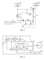
- the motor drive system includes a trigger switch 20, a switch control circuit 30, an electronic switch 40, a motor drive control circuit, an inverter 60 and a position sensor 80.
- the motor drive control circuit includes a voltage regulator 50, a microcontroller 55 and a driver 58, and is configured to output a drive signal to control a power mode of the inverter 60.
- the trigger switch 20 is connected between the power supply 10 and the switch control circuit 30.
- the trigger switch 20 is turned on in a case that the motor 70 is required to operate, and the trigger switch 20 is turned off in a case that the motor 70 is required to stop operating.
- the electronic switch 40 is connected between the power supply 10 and the voltage regulator 50, and is configured to control a supply path between the power supply 10 and the voltage regulator 50 to be turned on or turned off.
- the voltage regulator 50 is connected to the microcontroller 55 and the driver 58, and is configured to reduce a voltage provided by the power supply 10 to a voltage of 5 volts and a voltage of 12 volts.
- the voltage of 5 volts is provided for the microcontroller 55, and the voltage of 12 volts is provided for the driver 58.
- the voltage regulator 50 may regulate the voltage of the power supply 10 into other voltages of different magnitudes based on requirements of electronic elements in different motors. If the voltage provided by the power supply 10 can directly drive the microcontroller 55 and the driver 58, the voltage regulator 50 may not be provided.
- the driver 58 is configured to perform voltage boosting or current amplifying on the drive signal outputted by the microcontroller 55 and then transmits the processed signal to the inverter 60.
- the driver 58 may be a gate driver. It should be understood that if the drive signal outputted by the microcontroller 55 is high enough to drive semiconductor switch elements of the inverter 60, the driver 58 may not be provided.
- the driver 58 is connected between the microcontroller 55 and the inverter 60.
- the inverter 60 is directly connected across the power supply 10 and is connected to the motor 70.
- the inverter 60 may be a three-phase inverter, which includes multiple, for example, six semiconductor switch elements.
- the position sensor 80 may be preferably a Hall-effect sensor which is arranged on the stator or arranged at a location near the rotor, and is configured to detect a position of a magnetic pole of the rotor. It should be understood that, as an alternative, the position of the magnetic pole of the rotor may be detected in a sensorless way.
- the microcontroller 55 outputs, based on the position of the magnetic pole of the rotor detected by position sensor 80, a PWM drive signal to control the semiconductor switch elements in the inverter 60 to be turned on or turned off, so as to control a power mode of motor 70 to commutate the motor and/or control the speed of the motor.
- the motor 70 can be turned on or turned off by simply controlling the supply path between the motor drive control circuit and the power supply 10 to be turned on or turned off.
- the motor drive system drives the motor 70 to operate, and the motor 70 drives a working head of the electric tool hosting the motor to operate.
- the switch control circuit 30 is connected to the power supply 10 through the trigger switch 20 and control, based on a turn-on or turn-off action of the trigger switch 20, the electric switch 40 to be turned on or turned off, and thereby controlling an operation state of the entire motor drive system.
- the switch control circuit 30 includes a triode Q2, resistors R1 to R4 and a diode D1.
- An anode of the diode D1 is connected to the power supply 10 through the trigger switch 20, and a cathode of the diode D1 is connected to the ground through a capacitor C1 and is also connected to a base of the triode Q2 through the resistor R4.
- the base of the triode Q2 is also connected to an emitter of the triode Q2 through the resistor R3.
- a collector of the triode Q2 is connected to the power supply 10 through the resistor R1 and the resistor R2 which are connected in series, and a node between the resistor R1 and the resistor R2 is connected to a control terminal of the electronic switch 40.
- the electronic switch 40 is a p-channel metal-oxide-semiconductor field-effect transistor (MOSFET) Q1, which has a gate serving as the control terminal of the electronic switch 40 and connected to the node between the resistor R1 and the resistor R2, a source serving as a first terminal of the electronic switch 40 and connected to the power supply 10, and a drain serving as a second terminal of the electronic switch 40 and connected to the voltage regulator 50.
- MOSFET metal-oxide-semiconductor field-effect transistor
- the first electronic switch 40 may be a PNP triode having a base, an emitter and a collector which serves as the control terminal, the first terminal and the second terminal of the electronic switch 40 respectively.
- the triode Q2 also serves as an electronic switch element.
- the triode Q2 may be replaced by a MOSFET element.
- An external switch pin 550 of the microcontroller 55 is connected to the trigger switch 20.
- an operation of the trigger switch 20 is read in a real-time manner.
- the trigger switch 20 is turned on, the external switch pin 550 receives a high-level signal; and when the trigger switch 20 is turned off, the external switch pin 550 receives a low-level signal.
- the microcontroller 55 controls, after learning that the trigger switch 20 is turned off, the motor 70 to perform a braking operation.
- the triode Q2 Before the trigger switch 20 is pressed, i.e., when the trigger switch 20 is in an off-state, the triode Q2 is in an off-state, a voltage at the node between the resistor R1 and the resistor R2 is equal to a voltage of the power supply 10, the MOSFET Q1 is in an off-state, no power supply is provided for the voltage regulator 50, and the motor 70 does not operate.
- the trigger switch 20 When the trigger switch 20 is pressed, a current provided by the power supply 10 will charge the capacitor C1 in the switch control circuit 30. When a voltage across the capacitor C1 reaches a turn-on voltage for the triode Q2, the triode Q2 is turned on, and the current provided by the power supply 10 flows through the resistor R2 and the resistor R1 and generates a voltage drop at the node between the resistor R2 and the resistor R1. Therefore, the MOSFET Q1 is turned on, and the power supply 10 provides power for the voltage regulator 50 through the MOSFET Q1.
- the motor drive system is in operation, and the motor 70 drives, under the drive of the microcontroller 55, the working head of the electric tool to operate.
- the external switch pin 550 of the microcontroller 55 reads the operation of the trigger switch 20 in a real-time manner.
- the MOSFET Q1 When the trigger switch 20 is turned off, because the capacitor C1 will discharge and the voltage across the capacitor C1 will drop below a pre-set value such as 0.7 volts after a delay time since the trigger switch 20 is turned off, the MOSFET Q1 will not be turned off immediately but maintain the on-state during the time that the voltage across the capacitor C1 is higher than the pre-set value.
- the microcontroller 55 when learning the turn-off operation of the trigger switch 20, sends the drive signal to the inverter 60 through the driver 58 to control the motor 70 to perform the braking operation.
- the motor itself generates electromagnetic torque which has a direction opposite to a rotation direction of the motor, and the motor absorbs mechanical energy from the working head, converts the mechanical energy into electrical energy and consumes the electrical energy in the internal of the motor, to stop rotation of the motor as soon as possible. In an example, it only takes the motor 70 0.3 seconds to brake.
- the capacitor C1 and the resistor R4 constitutes a delay circuit. A delay time of the delay circuit is with respect to a resistance value of the resistor R4 and a capacitance value of the capacitor C1.
- the MOSFET Q1 can be turned off after delaying for a delay time of 0.3 seconds from a time that the trigger switch 20 is turned off, and the microcontroller 55 is ensured to complete the braking operation of the motor in the delay time.
- the delay time of the delay circuit may be adjusted accordingly based on different requirements of products to which the motor is applied.
- the diode D1 is a unidirectional element, which can avoid a discharge current flowing through the trigger switch 20 to the microcontroller 55 when the capacitor C1 is discharging, so as to protect the microcontroller 55.
- the embodiment when the trigger switch 20 is turned off, the motor completes the braking operation during the delay time, which effectively protects the motor.
- the trigger switch 20 since the trigger switch 20 is not connected between the power supply 10 and the inverter 60, a current flowing through the trigger switch 20 when the motor is turned on or turned off is greatly reduced to tens of milliamperes, while an operating current of the motor reaches tens of amperes. That is, the current flowing through the trigger switch 20 is lower than 1/100 of the operating current of the motor. Therefore, there is no need to use an expensive high-current trigger switch, instead, a trigger switch having a rated current lower than 100 milliamperes can be selected, which has a low cost.
- FIG. 4 and Figure 5 show circuit diagrams of a motor drive system according to another embodiment in the present disclosure.
- Functions and connection relation of the trigger switch 20, the electronic switch 40, the voltage regulator 50, the driver 58, the inverter 60 and the position sensor 80 are similar to those in the above embodiment.
- the switch control circuit 30 further includes a diode D2 and a resistor R5.
- An anode of the diode D2 is connected to a trigger signal pin 552 of the microcontroller 55.
- the anode of the diode D2 is also connected to a voltage V3P3D through the resistor R5.
- a cathode of the diode D2 is connected to a cathode of the diode D1.
- the function of cutting off the supply path between the power supply 10 and the voltage regulator 50 when a braking operation of a motor is completed after the trigger switch 20 is turned off is achieved by a program of the microcontroller 55.
- the microcontroller 55 stores a motor braking program.
- the trigger signal pin 552 of the microcontroller 55 outputs a high-level signal to the switch control circuit 30.
- the microcontroller 55 executes the motor braking program by maintaining the high-level signal at the trigger signal pin 552 and changes the high-level signal to a low-level signal after the braking operation of the motor is completed.
- the triode Q2 Before the trigger switch 20 is pressed, i.e., when the trigger switch 20 is in an off-state, the triode Q2 is in an off-state, a voltage at the node between the resistor R1 and the resistor R2 is equal to a voltage of the power supply 10, the MOSFET Q1 is turned off, no power supply is provided for the voltage regulator 50, and the motor 70 does not operate.
- the triode Q2 When the trigger switch 20 is pressed, a current provided by the power supply 10 flows through the resistor R4 and the resistor R3, the triode Q2 is turned on when a divided voltage generated by the resistors R3 and R4 reaches a turn-on voltage for the triode Q2, and a current provided by the power supply 10 flows through the resistor R2 and the resistor R1 and generates a voltage drop relative to the power supply 10 at the node between the resistor R2 and the resistor R1. Therefore, the MOSFET Q1 is turned on, and the power supply 10 provides power for the voltage regulator 50 through the MOSFET Q1.
- the motor drive system As described above, the motor drive system is in operation, and the motor 70 drives, under the drive of the microcontroller 55, a working head of the electric tool to operate.
- the microcontroller 55 outputs a high-level signal at its trigger signal pin 552 to the diode D2, and the microcontroller 55 also monitors an operation of the trigger switch 20 in a real-time manner via the external switch pin 550 of the microcontroller 55.
- the external switch pin 550 of the microcontroller 55 learns a turn-off action of the trigger switch 20, and the trigger signal pin 552 of the microcontroller 55 keeps outputting the high-level signal and executes the braking program to sends a drive signal to the inverter 60 through the driver 58 to control the motor 70 to perform a braking operation.
- the triode Q2 and the MOSFET Q1 remain in an on-state, that is, the power supply keeps providing power for the voltage regulator 50.
- the trigger signal pin 552 of the microcontroller 55 outputs a low-level signal.
- both the anode of the diode D1 and the anode of the diode D2 receive the low-level signal, both the diode D1 and the diode D2 are turned off, and the triode Q2 is turned off, and then the MOSFET Q1 is turned off, so that the supply path between the power supply 10 and the voltage regulator 50 is turned off, and the motor 70 stops operating.
- a capacitor with a small capacitance value such as 100 nanofarads, may be selected as the capacitor C1.
- a filtering function of the capacitor C1 is mainly applied.
- the resistor R5 is a pull-up resistor, which stabilizes an output level of the trigger signal pin 552 of the microcontroller 55.
- a delay time from the trigger switch being turned off to the MOSFET Q1 being turned off is controlled by the microcontroller 55.
- the microcontroller 55 may also perform other operations during the delay time, such as controlling an LED which is used to indicate a state of the motor, to be turned off after blinking.
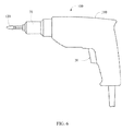
- FIG. 6 is a schematic diagram of an electric tool, such as an electric drill, using a motor drive system described above.
- the electric drill 100 includes a housing 110, a working head 120 extending out from the housing, and the motor 70 and the motor drive system as described above which are arranged inside the housing 110.
- a trigger switch 20 is arranged on a handle at the lower part of the housing 110 and is operable by a user manually, to control the electric tool to be turned on or turned off.
- the above motor drive system is also applicable to other electric tools, such as an electric screwdriver, a hand mill and an electric saw.
- a current flowing through the trigger switch 20 is greatly reduced, which may be lower than 20 milliamperes.
- a switch having a rated current of 20 milliamperes may be selected as the trigger switch 20, leading to a low cost.
- a supply path between the power supply and the voltage regulator may be cut off after delaying for a period of time from a time that the trigger switch is turned off, and a braking operation is completed by the motor during the delay time, which can effectively protect the motor.
- the motor drive system according to the present disclosure is not only applicable to driving a brushless direct current motor, but also applicable to driving other types of motors.
- the trigger switch and the motor in two different current branches respectively with the trigger switch being connected in series to the power supply and with the electronic switch being connected between the power supply and the microcontroller, and by configuring the switch control circuit to control, based on a state including an on-state and an off-state of the trigger switch, a state of the electronic switch, the current flowing through the trigger switch is lower than the operating current of the motor while the motor drive system is powered to operate , and the electronic switch is delayed to be turned off after the trigger switch is turned off, to control the motor to be powered off later than a time that the trigger switch is turned off.
- the switch control circuit to control, based on a state including an on-state and an off-state of the trigger switch, a state of the electronic switch, the current flowing through the trigger switch is lower than the operating current of the motor while the motor drive system is powered to operate , and the electronic switch is delayed to be turned off after the trigger switch is turned off, to control the motor to be powered off later than a time that the trigger switch is turned off.
Landscapes
- Engineering & Computer Science (AREA)
- Power Engineering (AREA)
- Mechanical Engineering (AREA)
- Computer Security & Cryptography (AREA)
- Stopping Of Electric Motors (AREA)
- Portable Power Tools In General (AREA)
- Control Of Ac Motors In General (AREA)
- Control Of Electric Motors In General (AREA)
Applications Claiming Priority (1)
| Application Number | Priority Date | Filing Date | Title |
|---|---|---|---|
| CN201510641142.0A CN106559025B (zh) | 2015-09-30 | 2015-09-30 | 电动工具及其电机驱动系统 |
Publications (2)
| Publication Number | Publication Date |
|---|---|
| EP3150338A1 true EP3150338A1 (fr) | 2017-04-05 |
| EP3150338B1 EP3150338B1 (fr) | 2019-02-27 |
Family
ID=57144725
Family Applications (1)
| Application Number | Title | Priority Date | Filing Date |
|---|---|---|---|
| EP16188403.6A Active EP3150338B1 (fr) | 2015-09-30 | 2016-09-12 | Outillage électrique, moteur et système d'entraînement moteur |
Country Status (8)
| Country | Link |
|---|---|
| US (1) | US10418919B2 (fr) |
| EP (1) | EP3150338B1 (fr) |
| JP (2) | JP3207985U (fr) |
| KR (1) | KR20170038723A (fr) |
| CN (1) | CN106559025B (fr) |
| BR (1) | BR102016022504A2 (fr) |
| DE (1) | DE202016105069U1 (fr) |
| MX (1) | MX366879B (fr) |
Cited By (3)
| Publication number | Priority date | Publication date | Assignee | Title |
|---|---|---|---|---|
| EP3522321A1 (fr) * | 2018-02-02 | 2019-08-07 | TTI (Macao Commercial Offshore) Limited | Outils électriques dotés d'un commutateur de sauvegarde manuelle et son procédé de fonctionnement |
| EP4438233A1 (fr) * | 2023-03-29 | 2024-10-02 | Nanjing Chervon Industry Co., Ltd. | Outil électrique |
| EP4579990A3 (fr) * | 2023-12-29 | 2025-08-06 | Greenworks (Jiangsu) Co., Ltd. | Circuit de commande de démarrage, outil électrique et procédé de commande de démarrage associé |
Families Citing this family (15)
| Publication number | Priority date | Publication date | Assignee | Title |
|---|---|---|---|---|
| JP6978419B2 (ja) * | 2016-08-08 | 2021-12-08 | 日本電産サーボ株式会社 | モータ駆動回路 |
| CN107968602A (zh) * | 2017-12-11 | 2018-04-27 | 海尔优家智能科技(北京)有限公司 | 控制直流电机功耗的方法、电路、直流电机及存储介质 |
| WO2019187848A1 (fr) | 2018-03-30 | 2019-10-03 | 工機ホールディングス株式会社 | Outil de travail |
| EP3588524B1 (fr) | 2018-06-28 | 2020-08-05 | Black & Decker Inc. | Module de commutateur électronique doté d'une diode de retour intégrée |
| CN108873957B (zh) * | 2018-08-31 | 2024-02-06 | 广东贝迪机器人有限公司 | 一种电批控制电路系统 |
| CN110919600B (zh) * | 2018-09-18 | 2022-09-20 | 南京泉峰科技有限公司 | 电动工具及其启动方法 |
| CN110932233B (zh) * | 2018-09-18 | 2022-08-02 | 南京泉峰科技有限公司 | 电动工具及其控制方法 |
| CN111430200B (zh) * | 2019-01-10 | 2025-07-25 | 南京泉峰科技有限公司 | 电动工具 |
| CN111865181B (zh) * | 2020-07-31 | 2025-04-04 | 惠州拓邦电气技术有限公司 | 高压保护方法、装置、电路及电动设备 |
| CN114257157B (zh) * | 2020-09-21 | 2024-06-14 | 南京泉峰科技有限公司 | 电动工具及其控制方法 |
| CN114789125A (zh) * | 2021-01-25 | 2022-07-26 | 南京泉峰科技有限公司 | 电动胶枪 |
| EP4092903A1 (fr) * | 2021-05-17 | 2022-11-23 | Hilti Aktiengesellschaft | Unité électrique d'entraînement pour une machine-outil électrique et machine-outil électrique dotée dune unité électrique d'entraînement |
| CN115580200B (zh) * | 2021-07-06 | 2024-04-26 | 南京泉峰科技有限公司 | 电动工具及其驱动控制电路 |
| CN116214448B (zh) * | 2023-02-11 | 2025-06-24 | 江苏东成工具科技有限公司 | 一种上电判断的控制方法、电动工具及计算机可读介质 |
| EP4604382A4 (fr) * | 2023-06-02 | 2026-03-25 | Nanjing Chervon Ind Co Ltd | Outil électrique |
Citations (7)
| Publication number | Priority date | Publication date | Assignee | Title |
|---|---|---|---|---|
| EP2140983A2 (fr) * | 2008-07-04 | 2010-01-06 | Makita Corporation | Outil d'alimentation électrique |
| WO2012096198A2 (fr) * | 2011-01-14 | 2012-07-19 | Hitachi Koki Co., Ltd. | Dispositif d'alimentation électrique, inverseur et outil électrique |
| EP2674261A1 (fr) * | 2011-02-10 | 2013-12-18 | Makita Corporation | Outil électrique |
| WO2014014128A1 (fr) * | 2012-07-18 | 2014-01-23 | Hitachi Koki Co., Ltd. | Dispositif d'alimentation électrique |
| EP2713474A2 (fr) * | 2012-09-26 | 2014-04-02 | Panasonic Corporation | Circuit de commande d'entraînement et outil électrique |
| WO2015025677A1 (fr) * | 2013-08-22 | 2015-02-26 | 日立工機株式会社 | Outil électrique et polisseur utilisant celui-ci |
| US20150137717A1 (en) * | 2013-11-18 | 2015-05-21 | Makita Corporation | Braking apparatus for electric power tool |
Family Cites Families (16)
| Publication number | Priority date | Publication date | Assignee | Title |
|---|---|---|---|---|
| CN2111595U (zh) * | 1992-01-30 | 1992-07-29 | 吴伟 | 多功能电子开关 |
| US6234155B1 (en) * | 1998-06-12 | 2001-05-22 | Competition Cams, Inc. | Adjustable trigger switch for nitrous oxide injection application |
| US7137541B2 (en) * | 2004-04-02 | 2006-11-21 | Black & Decker Inc. | Fastening tool with mode selector switch |
| JP4735325B2 (ja) * | 2006-02-27 | 2011-07-27 | パナソニック電工株式会社 | 電動工具用制御駆動回路 |
| US7496460B2 (en) * | 2006-09-06 | 2009-02-24 | Eastway Fair Company Limited | Energy source monitoring and control system for power tools |
| JP2008068359A (ja) | 2006-09-14 | 2008-03-27 | Hitachi Koki Co Ltd | 留め具打込機 |
| JP2010088199A (ja) * | 2008-09-30 | 2010-04-15 | Fujisoku:Kk | トリガスイッチ内蔵モータ制御回路 |
| JP4793426B2 (ja) * | 2008-11-10 | 2011-10-12 | パナソニック電工株式会社 | 充電式電動工具 |
| TWI385509B (zh) * | 2009-07-23 | 2013-02-11 | Feeling Technology Corp | 電源供應控制電路 |
| BR112012008122A2 (pt) * | 2009-07-29 | 2016-03-01 | Hitachi Koki Kk | ferramenta de impacto |
| CN201577051U (zh) * | 2009-11-19 | 2010-09-08 | 中山大洋电机股份有限公司 | 一种软启动模块及其应用的电机控制器启动装置 |
| IT1401174B1 (it) | 2010-07-26 | 2013-07-12 | Sam Hydraulik Spa | Macchina a pistoni assiali |
| JP5491346B2 (ja) * | 2010-10-13 | 2014-05-14 | 株式会社マキタ | 電動工具およびプログラム |
| CN202177791U (zh) * | 2011-06-23 | 2012-03-28 | 黄泽光 | 一种汽车水箱定时控制装置 |
| JP5755988B2 (ja) * | 2011-09-30 | 2015-07-29 | 株式会社マキタ | 電動工具 |
| US9352456B2 (en) * | 2011-10-26 | 2016-05-31 | Black & Decker Inc. | Power tool with force sensing electronic clutch |
-
2015
- 2015-09-30 CN CN201510641142.0A patent/CN106559025B/zh active Active
-
2016
- 2016-09-12 EP EP16188403.6A patent/EP3150338B1/fr active Active
- 2016-09-13 DE DE202016105069.3U patent/DE202016105069U1/de not_active Expired - Lifetime
- 2016-09-27 MX MX2016012598A patent/MX366879B/es active IP Right Grant
- 2016-09-28 BR BR102016022504-3A patent/BR102016022504A2/pt not_active Application Discontinuation
- 2016-09-29 KR KR1020160125603A patent/KR20170038723A/ko not_active Abandoned
- 2016-09-30 US US15/282,720 patent/US10418919B2/en active Active
- 2016-09-30 JP JP2016004775U patent/JP3207985U/ja not_active Expired - Fee Related
- 2016-09-30 JP JP2016193414A patent/JP7075179B2/ja active Active
Patent Citations (7)
| Publication number | Priority date | Publication date | Assignee | Title |
|---|---|---|---|---|
| EP2140983A2 (fr) * | 2008-07-04 | 2010-01-06 | Makita Corporation | Outil d'alimentation électrique |
| WO2012096198A2 (fr) * | 2011-01-14 | 2012-07-19 | Hitachi Koki Co., Ltd. | Dispositif d'alimentation électrique, inverseur et outil électrique |
| EP2674261A1 (fr) * | 2011-02-10 | 2013-12-18 | Makita Corporation | Outil électrique |
| WO2014014128A1 (fr) * | 2012-07-18 | 2014-01-23 | Hitachi Koki Co., Ltd. | Dispositif d'alimentation électrique |
| EP2713474A2 (fr) * | 2012-09-26 | 2014-04-02 | Panasonic Corporation | Circuit de commande d'entraînement et outil électrique |
| WO2015025677A1 (fr) * | 2013-08-22 | 2015-02-26 | 日立工機株式会社 | Outil électrique et polisseur utilisant celui-ci |
| US20150137717A1 (en) * | 2013-11-18 | 2015-05-21 | Makita Corporation | Braking apparatus for electric power tool |
Cited By (3)
| Publication number | Priority date | Publication date | Assignee | Title |
|---|---|---|---|---|
| EP3522321A1 (fr) * | 2018-02-02 | 2019-08-07 | TTI (Macao Commercial Offshore) Limited | Outils électriques dotés d'un commutateur de sauvegarde manuelle et son procédé de fonctionnement |
| EP4438233A1 (fr) * | 2023-03-29 | 2024-10-02 | Nanjing Chervon Industry Co., Ltd. | Outil électrique |
| EP4579990A3 (fr) * | 2023-12-29 | 2025-08-06 | Greenworks (Jiangsu) Co., Ltd. | Circuit de commande de démarrage, outil électrique et procédé de commande de démarrage associé |
Also Published As
| Publication number | Publication date |
|---|---|
| DE202016105069U1 (de) | 2017-01-24 |
| CN106559025B (zh) | 2020-05-12 |
| BR102016022504A2 (pt) | 2017-07-25 |
| CN106559025A (zh) | 2017-04-05 |
| US10418919B2 (en) | 2019-09-17 |
| JP3207985U (ja) | 2016-12-15 |
| JP7075179B2 (ja) | 2022-05-25 |
| JP2017070200A (ja) | 2017-04-06 |
| MX366879B (es) | 2019-07-26 |
| MX2016012598A (es) | 2018-03-26 |
| EP3150338B1 (fr) | 2019-02-27 |
| US20170093308A1 (en) | 2017-03-30 |
| KR20170038723A (ko) | 2017-04-07 |
Similar Documents
| Publication | Publication Date | Title |
|---|---|---|
| EP3150338B1 (fr) | Outillage électrique, moteur et système d'entraînement moteur | |
| US9647585B2 (en) | Brushless direct-current motor and control for power tool | |
| US10525579B2 (en) | Electric tool | |
| US20180013360A1 (en) | Electronic braking of brushless dc motor in a power tool | |
| US20170288583A1 (en) | Power tool and motor drive system thereof | |
| AU2018100867A4 (en) | Energy recycle on power tools | |
| US20170288580A1 (en) | Power tool and motor drive system thereof | |
| US10892691B2 (en) | Control circuit and power tool | |
| US9716448B2 (en) | Power tool and control circuit thereof | |
| US11511387B2 (en) | Electric tool | |
| US20170288584A1 (en) | Power tool and motor drive system thereof | |
| EP3146627B1 (fr) | Limite de courant cycle par cycle pour outils électriques comprenant un moteur sans balais | |
| CN104617831A (zh) | 单相串励换向器电动机的驱动装置 | |
| JP2018057178A (ja) | 電気機器 | |
| JP6354080B2 (ja) | 電動工具 | |
| EP3995261B1 (fr) | Outil électrique et son procédé de commande | |
| CN109842327A (zh) | 电动工具 | |
| CN221328835U (zh) | 一种主轴电机控制电路 |
Legal Events
| Date | Code | Title | Description |
|---|---|---|---|
| PUAI | Public reference made under article 153(3) epc to a published international application that has entered the european phase |
Free format text: ORIGINAL CODE: 0009012 |
|
| STAA | Information on the status of an ep patent application or granted ep patent |
Free format text: STATUS: THE APPLICATION HAS BEEN PUBLISHED |
|
| AK | Designated contracting states |
Kind code of ref document: A1 Designated state(s): AL AT BE BG CH CY CZ DE DK EE ES FI FR GB GR HR HU IE IS IT LI LT LU LV MC MK MT NL NO PL PT RO RS SE SI SK SM TR |
|
| AX | Request for extension of the european patent |
Extension state: BA ME |
|
| STAA | Information on the status of an ep patent application or granted ep patent |
Free format text: STATUS: REQUEST FOR EXAMINATION WAS MADE |
|
| 17P | Request for examination filed |
Effective date: 20170927 |
|
| RBV | Designated contracting states (corrected) |
Designated state(s): AL AT BE BG CH CY CZ DE DK EE ES FI FR GB GR HR HU IE IS IT LI LT LU LV MC MK MT NL NO PL PT RO RS SE SI SK SM TR |
|
| GRAP | Despatch of communication of intention to grant a patent |
Free format text: ORIGINAL CODE: EPIDOSNIGR1 |
|
| STAA | Information on the status of an ep patent application or granted ep patent |
Free format text: STATUS: GRANT OF PATENT IS INTENDED |
|
| INTG | Intention to grant announced |
Effective date: 20180912 |
|
| GRAS | Grant fee paid |
Free format text: ORIGINAL CODE: EPIDOSNIGR3 |
|
| GRAA | (expected) grant |
Free format text: ORIGINAL CODE: 0009210 |
|
| STAA | Information on the status of an ep patent application or granted ep patent |
Free format text: STATUS: THE PATENT HAS BEEN GRANTED |
|
| RAP1 | Party data changed (applicant data changed or rights of an application transferred) |
Owner name: JOHNSON ELECTRIC INTERNATIONAL AG |
|
| AK | Designated contracting states |
Kind code of ref document: B1 Designated state(s): AL AT BE BG CH CY CZ DE DK EE ES FI FR GB GR HR HU IE IS IT LI LT LU LV MC MK MT NL NO PL PT RO RS SE SI SK SM TR |
|
| REG | Reference to a national code |
Ref country code: GB Ref legal event code: FG4D |
|
| REG | Reference to a national code |
Ref country code: CH Ref legal event code: EP |
|
| REG | Reference to a national code |
Ref country code: AT Ref legal event code: REF Ref document number: 1100653 Country of ref document: AT Kind code of ref document: T Effective date: 20190315 |
|
| REG | Reference to a national code |
Ref country code: IE Ref legal event code: FG4D |
|
| REG | Reference to a national code |
Ref country code: DE Ref legal event code: R096 Ref document number: 602016010295 Country of ref document: DE |
|
| REG | Reference to a national code |
Ref country code: NL Ref legal event code: MP Effective date: 20190227 |
|
| REG | Reference to a national code |
Ref country code: LT Ref legal event code: MG4D |
|
| PG25 | Lapsed in a contracting state [announced via postgrant information from national office to epo] |
Ref country code: SE Free format text: LAPSE BECAUSE OF FAILURE TO SUBMIT A TRANSLATION OF THE DESCRIPTION OR TO PAY THE FEE WITHIN THE PRESCRIBED TIME-LIMIT Effective date: 20190227 Ref country code: NO Free format text: LAPSE BECAUSE OF FAILURE TO SUBMIT A TRANSLATION OF THE DESCRIPTION OR TO PAY THE FEE WITHIN THE PRESCRIBED TIME-LIMIT Effective date: 20190527 Ref country code: PT Free format text: LAPSE BECAUSE OF FAILURE TO SUBMIT A TRANSLATION OF THE DESCRIPTION OR TO PAY THE FEE WITHIN THE PRESCRIBED TIME-LIMIT Effective date: 20190627 Ref country code: FI Free format text: LAPSE BECAUSE OF FAILURE TO SUBMIT A TRANSLATION OF THE DESCRIPTION OR TO PAY THE FEE WITHIN THE PRESCRIBED TIME-LIMIT Effective date: 20190227 Ref country code: LT Free format text: LAPSE BECAUSE OF FAILURE TO SUBMIT A TRANSLATION OF THE DESCRIPTION OR TO PAY THE FEE WITHIN THE PRESCRIBED TIME-LIMIT Effective date: 20190227 Ref country code: NL Free format text: LAPSE BECAUSE OF FAILURE TO SUBMIT A TRANSLATION OF THE DESCRIPTION OR TO PAY THE FEE WITHIN THE PRESCRIBED TIME-LIMIT Effective date: 20190227 |
|
| PG25 | Lapsed in a contracting state [announced via postgrant information from national office to epo] |
Ref country code: IS Free format text: LAPSE BECAUSE OF FAILURE TO SUBMIT A TRANSLATION OF THE DESCRIPTION OR TO PAY THE FEE WITHIN THE PRESCRIBED TIME-LIMIT Effective date: 20190627 Ref country code: RS Free format text: LAPSE BECAUSE OF FAILURE TO SUBMIT A TRANSLATION OF THE DESCRIPTION OR TO PAY THE FEE WITHIN THE PRESCRIBED TIME-LIMIT Effective date: 20190227 Ref country code: LV Free format text: LAPSE BECAUSE OF FAILURE TO SUBMIT A TRANSLATION OF THE DESCRIPTION OR TO PAY THE FEE WITHIN THE PRESCRIBED TIME-LIMIT Effective date: 20190227 Ref country code: HR Free format text: LAPSE BECAUSE OF FAILURE TO SUBMIT A TRANSLATION OF THE DESCRIPTION OR TO PAY THE FEE WITHIN THE PRESCRIBED TIME-LIMIT Effective date: 20190227 Ref country code: GR Free format text: LAPSE BECAUSE OF FAILURE TO SUBMIT A TRANSLATION OF THE DESCRIPTION OR TO PAY THE FEE WITHIN THE PRESCRIBED TIME-LIMIT Effective date: 20190528 Ref country code: BG Free format text: LAPSE BECAUSE OF FAILURE TO SUBMIT A TRANSLATION OF THE DESCRIPTION OR TO PAY THE FEE WITHIN THE PRESCRIBED TIME-LIMIT Effective date: 20190527 |
|
| REG | Reference to a national code |
Ref country code: AT Ref legal event code: MK05 Ref document number: 1100653 Country of ref document: AT Kind code of ref document: T Effective date: 20190227 |
|
| PG25 | Lapsed in a contracting state [announced via postgrant information from national office to epo] |
Ref country code: CZ Free format text: LAPSE BECAUSE OF FAILURE TO SUBMIT A TRANSLATION OF THE DESCRIPTION OR TO PAY THE FEE WITHIN THE PRESCRIBED TIME-LIMIT Effective date: 20190227 Ref country code: ES Free format text: LAPSE BECAUSE OF FAILURE TO SUBMIT A TRANSLATION OF THE DESCRIPTION OR TO PAY THE FEE WITHIN THE PRESCRIBED TIME-LIMIT Effective date: 20190227 Ref country code: AL Free format text: LAPSE BECAUSE OF FAILURE TO SUBMIT A TRANSLATION OF THE DESCRIPTION OR TO PAY THE FEE WITHIN THE PRESCRIBED TIME-LIMIT Effective date: 20190227 Ref country code: RO Free format text: LAPSE BECAUSE OF FAILURE TO SUBMIT A TRANSLATION OF THE DESCRIPTION OR TO PAY THE FEE WITHIN THE PRESCRIBED TIME-LIMIT Effective date: 20190227 Ref country code: DK Free format text: LAPSE BECAUSE OF FAILURE TO SUBMIT A TRANSLATION OF THE DESCRIPTION OR TO PAY THE FEE WITHIN THE PRESCRIBED TIME-LIMIT Effective date: 20190227 Ref country code: IT Free format text: LAPSE BECAUSE OF FAILURE TO SUBMIT A TRANSLATION OF THE DESCRIPTION OR TO PAY THE FEE WITHIN THE PRESCRIBED TIME-LIMIT Effective date: 20190227 Ref country code: EE Free format text: LAPSE BECAUSE OF FAILURE TO SUBMIT A TRANSLATION OF THE DESCRIPTION OR TO PAY THE FEE WITHIN THE PRESCRIBED TIME-LIMIT Effective date: 20190227 Ref country code: SK Free format text: LAPSE BECAUSE OF FAILURE TO SUBMIT A TRANSLATION OF THE DESCRIPTION OR TO PAY THE FEE WITHIN THE PRESCRIBED TIME-LIMIT Effective date: 20190227 |
|
| REG | Reference to a national code |
Ref country code: DE Ref legal event code: R097 Ref document number: 602016010295 Country of ref document: DE |
|
| PG25 | Lapsed in a contracting state [announced via postgrant information from national office to epo] |
Ref country code: PL Free format text: LAPSE BECAUSE OF FAILURE TO SUBMIT A TRANSLATION OF THE DESCRIPTION OR TO PAY THE FEE WITHIN THE PRESCRIBED TIME-LIMIT Effective date: 20190227 Ref country code: SM Free format text: LAPSE BECAUSE OF FAILURE TO SUBMIT A TRANSLATION OF THE DESCRIPTION OR TO PAY THE FEE WITHIN THE PRESCRIBED TIME-LIMIT Effective date: 20190227 |
|
| PG25 | Lapsed in a contracting state [announced via postgrant information from national office to epo] |
Ref country code: AT Free format text: LAPSE BECAUSE OF FAILURE TO SUBMIT A TRANSLATION OF THE DESCRIPTION OR TO PAY THE FEE WITHIN THE PRESCRIBED TIME-LIMIT Effective date: 20190227 |
|
| PLBE | No opposition filed within time limit |
Free format text: ORIGINAL CODE: 0009261 |
|
| STAA | Information on the status of an ep patent application or granted ep patent |
Free format text: STATUS: NO OPPOSITION FILED WITHIN TIME LIMIT |
|
| 26N | No opposition filed |
Effective date: 20191128 |
|
| PG25 | Lapsed in a contracting state [announced via postgrant information from national office to epo] |
Ref country code: SI Free format text: LAPSE BECAUSE OF FAILURE TO SUBMIT A TRANSLATION OF THE DESCRIPTION OR TO PAY THE FEE WITHIN THE PRESCRIBED TIME-LIMIT Effective date: 20190227 |
|
| PG25 | Lapsed in a contracting state [announced via postgrant information from national office to epo] |
Ref country code: TR Free format text: LAPSE BECAUSE OF FAILURE TO SUBMIT A TRANSLATION OF THE DESCRIPTION OR TO PAY THE FEE WITHIN THE PRESCRIBED TIME-LIMIT Effective date: 20190227 |
|
| PG25 | Lapsed in a contracting state [announced via postgrant information from national office to epo] |
Ref country code: MC Free format text: LAPSE BECAUSE OF FAILURE TO SUBMIT A TRANSLATION OF THE DESCRIPTION OR TO PAY THE FEE WITHIN THE PRESCRIBED TIME-LIMIT Effective date: 20190227 |
|
| REG | Reference to a national code |
Ref country code: CH Ref legal event code: PL |
|
| PG25 | Lapsed in a contracting state [announced via postgrant information from national office to epo] |
Ref country code: CH Free format text: LAPSE BECAUSE OF NON-PAYMENT OF DUE FEES Effective date: 20190930 Ref country code: LU Free format text: LAPSE BECAUSE OF NON-PAYMENT OF DUE FEES Effective date: 20190912 Ref country code: IE Free format text: LAPSE BECAUSE OF NON-PAYMENT OF DUE FEES Effective date: 20190912 Ref country code: LI Free format text: LAPSE BECAUSE OF NON-PAYMENT OF DUE FEES Effective date: 20190930 |
|
| REG | Reference to a national code |
Ref country code: BE Ref legal event code: MM Effective date: 20190930 |
|
| PG25 | Lapsed in a contracting state [announced via postgrant information from national office to epo] |
Ref country code: BE Free format text: LAPSE BECAUSE OF NON-PAYMENT OF DUE FEES Effective date: 20190930 |
|
| GBPC | Gb: european patent ceased through non-payment of renewal fee |
Effective date: 20200912 |
|
| PG25 | Lapsed in a contracting state [announced via postgrant information from national office to epo] |
Ref country code: CY Free format text: LAPSE BECAUSE OF FAILURE TO SUBMIT A TRANSLATION OF THE DESCRIPTION OR TO PAY THE FEE WITHIN THE PRESCRIBED TIME-LIMIT Effective date: 20190227 |
|
| PG25 | Lapsed in a contracting state [announced via postgrant information from national office to epo] |
Ref country code: MT Free format text: LAPSE BECAUSE OF FAILURE TO SUBMIT A TRANSLATION OF THE DESCRIPTION OR TO PAY THE FEE WITHIN THE PRESCRIBED TIME-LIMIT Effective date: 20190227 Ref country code: HU Free format text: LAPSE BECAUSE OF FAILURE TO SUBMIT A TRANSLATION OF THE DESCRIPTION OR TO PAY THE FEE WITHIN THE PRESCRIBED TIME-LIMIT; INVALID AB INITIO Effective date: 20160912 |
|
| PG25 | Lapsed in a contracting state [announced via postgrant information from national office to epo] |
Ref country code: GB Free format text: LAPSE BECAUSE OF NON-PAYMENT OF DUE FEES Effective date: 20200912 |
|
| PGFP | Annual fee paid to national office [announced via postgrant information from national office to epo] |
Ref country code: FR Payment date: 20210812 Year of fee payment: 6 |
|
| PG25 | Lapsed in a contracting state [announced via postgrant information from national office to epo] |
Ref country code: MK Free format text: LAPSE BECAUSE OF FAILURE TO SUBMIT A TRANSLATION OF THE DESCRIPTION OR TO PAY THE FEE WITHIN THE PRESCRIBED TIME-LIMIT Effective date: 20190227 |
|
| REG | Reference to a national code |
Ref country code: DE Ref legal event code: R084 Ref document number: 602016010295 Country of ref document: DE |
|
| PG25 | Lapsed in a contracting state [announced via postgrant information from national office to epo] |
Ref country code: FR Free format text: LAPSE BECAUSE OF NON-PAYMENT OF DUE FEES Effective date: 20220930 |
|
| P01 | Opt-out of the competence of the unified patent court (upc) registered |
Effective date: 20230628 |
|
| PGFP | Annual fee paid to national office [announced via postgrant information from national office to epo] |
Ref country code: DE Payment date: 20250926 Year of fee payment: 10 |