EP3150809A1 - Moteur à combustion interne - Google Patents
Moteur à combustion interne Download PDFInfo
- Publication number
- EP3150809A1 EP3150809A1 EP16182972.6A EP16182972A EP3150809A1 EP 3150809 A1 EP3150809 A1 EP 3150809A1 EP 16182972 A EP16182972 A EP 16182972A EP 3150809 A1 EP3150809 A1 EP 3150809A1
- Authority
- EP
- European Patent Office
- Prior art keywords
- rocker arm
- combustion engine
- internal combustion
- exhaust
- abutting surface
- Prior art date
- Legal status (The legal status is an assumption and is not a legal conclusion. Google has not performed a legal analysis and makes no representation as to the accuracy of the status listed.)
- Granted
Links
Images




Classifications
-
- F—MECHANICAL ENGINEERING; LIGHTING; HEATING; WEAPONS; BLASTING
- F01—MACHINES OR ENGINES IN GENERAL; ENGINE PLANTS IN GENERAL; STEAM ENGINES
- F01L—CYCLICALLY OPERATING VALVES FOR MACHINES OR ENGINES
- F01L13/00—Modifications of valve-gear to facilitate reversing, braking, starting, changing compression ratio, or other specific operations
- F01L13/08—Modifications of valve-gear to facilitate reversing, braking, starting, changing compression ratio, or other specific operations for decompression, e.g. during starting; for changing compression ratio
-
- F—MECHANICAL ENGINEERING; LIGHTING; HEATING; WEAPONS; BLASTING
- F01—MACHINES OR ENGINES IN GENERAL; ENGINE PLANTS IN GENERAL; STEAM ENGINES
- F01L—CYCLICALLY OPERATING VALVES FOR MACHINES OR ENGINES
- F01L1/00—Valve-gear or valve arrangements, e.g. lift-valve gear
- F01L1/02—Valve drive
- F01L1/04—Valve drive by means of cams, camshafts, cam discs, eccentrics or the like
- F01L1/047—Camshafts
- F01L1/053—Camshafts overhead type
-
- F—MECHANICAL ENGINEERING; LIGHTING; HEATING; WEAPONS; BLASTING
- F01—MACHINES OR ENGINES IN GENERAL; ENGINE PLANTS IN GENERAL; STEAM ENGINES
- F01L—CYCLICALLY OPERATING VALVES FOR MACHINES OR ENGINES
- F01L1/00—Valve-gear or valve arrangements, e.g. lift-valve gear
- F01L1/12—Transmitting gear between valve drive and valve
- F01L1/18—Rocking arms or levers
- F01L1/181—Centre pivot rocking arms
-
- F—MECHANICAL ENGINEERING; LIGHTING; HEATING; WEAPONS; BLASTING
- F01—MACHINES OR ENGINES IN GENERAL; ENGINE PLANTS IN GENERAL; STEAM ENGINES
- F01L—CYCLICALLY OPERATING VALVES FOR MACHINES OR ENGINES
- F01L1/00—Valve-gear or valve arrangements, e.g. lift-valve gear
- F01L1/26—Valve-gear or valve arrangements, e.g. lift-valve gear characterised by the provision of two or more valves operated simultaneously by same transmitting-gear; peculiar to machines or engines with more than two lift-valves per cylinder
-
- F—MECHANICAL ENGINEERING; LIGHTING; HEATING; WEAPONS; BLASTING
- F01—MACHINES OR ENGINES IN GENERAL; ENGINE PLANTS IN GENERAL; STEAM ENGINES
- F01L—CYCLICALLY OPERATING VALVES FOR MACHINES OR ENGINES
- F01L1/00—Valve-gear or valve arrangements, e.g. lift-valve gear
- F01L1/26—Valve-gear or valve arrangements, e.g. lift-valve gear characterised by the provision of two or more valves operated simultaneously by same transmitting-gear; peculiar to machines or engines with more than two lift-valves per cylinder
- F01L1/267—Valve-gear or valve arrangements, e.g. lift-valve gear characterised by the provision of two or more valves operated simultaneously by same transmitting-gear; peculiar to machines or engines with more than two lift-valves per cylinder with means for varying the timing or the lift of the valves
-
- F—MECHANICAL ENGINEERING; LIGHTING; HEATING; WEAPONS; BLASTING
- F01—MACHINES OR ENGINES IN GENERAL; ENGINE PLANTS IN GENERAL; STEAM ENGINES
- F01L—CYCLICALLY OPERATING VALVES FOR MACHINES OR ENGINES
- F01L13/00—Modifications of valve-gear to facilitate reversing, braking, starting, changing compression ratio, or other specific operations
- F01L13/08—Modifications of valve-gear to facilitate reversing, braking, starting, changing compression ratio, or other specific operations for decompression, e.g. during starting; for changing compression ratio
- F01L13/085—Modifications of valve-gear to facilitate reversing, braking, starting, changing compression ratio, or other specific operations for decompression, e.g. during starting; for changing compression ratio the valve-gear having an auxiliary cam protruding from the main cam profile
-
- F—MECHANICAL ENGINEERING; LIGHTING; HEATING; WEAPONS; BLASTING
- F02—COMBUSTION ENGINES; HOT-GAS OR COMBUSTION-PRODUCT ENGINE PLANTS
- F02B—INTERNAL-COMBUSTION PISTON ENGINES; COMBUSTION ENGINES IN GENERAL
- F02B75/00—Other engines
- F02B75/16—Engines characterised by number of cylinders, e.g. single-cylinder engines
-
- F—MECHANICAL ENGINEERING; LIGHTING; HEATING; WEAPONS; BLASTING
- F02—COMBUSTION ENGINES; HOT-GAS OR COMBUSTION-PRODUCT ENGINE PLANTS
- F02D—CONTROLLING COMBUSTION ENGINES
- F02D13/00—Controlling the engine output power by varying inlet or exhaust valve operating characteristics, e.g. timing
- F02D13/02—Controlling the engine output power by varying inlet or exhaust valve operating characteristics, e.g. timing during engine operation
- F02D13/0242—Variable control of the exhaust valves only
- F02D13/0249—Variable control of the exhaust valves only changing the valve timing only
-
- F—MECHANICAL ENGINEERING; LIGHTING; HEATING; WEAPONS; BLASTING
- F02—COMBUSTION ENGINES; HOT-GAS OR COMBUSTION-PRODUCT ENGINE PLANTS
- F02D—CONTROLLING COMBUSTION ENGINES
- F02D13/00—Controlling the engine output power by varying inlet or exhaust valve operating characteristics, e.g. timing
- F02D13/02—Controlling the engine output power by varying inlet or exhaust valve operating characteristics, e.g. timing during engine operation
- F02D13/0273—Multiple actuations of a valve within an engine cycle
-
- F—MECHANICAL ENGINEERING; LIGHTING; HEATING; WEAPONS; BLASTING
- F01—MACHINES OR ENGINES IN GENERAL; ENGINE PLANTS IN GENERAL; STEAM ENGINES
- F01L—CYCLICALLY OPERATING VALVES FOR MACHINES OR ENGINES
- F01L1/00—Valve-gear or valve arrangements, e.g. lift-valve gear
- F01L1/02—Valve drive
- F01L1/04—Valve drive by means of cams, camshafts, cam discs, eccentrics or the like
- F01L1/047—Camshafts
- F01L1/053—Camshafts overhead type
- F01L2001/0535—Single overhead camshafts [SOHC]
-
- F—MECHANICAL ENGINEERING; LIGHTING; HEATING; WEAPONS; BLASTING
- F01—MACHINES OR ENGINES IN GENERAL; ENGINE PLANTS IN GENERAL; STEAM ENGINES
- F01L—CYCLICALLY OPERATING VALVES FOR MACHINES OR ENGINES
- F01L13/00—Modifications of valve-gear to facilitate reversing, braking, starting, changing compression ratio, or other specific operations
- F01L2013/10—Auxiliary actuators for variable valve timing
- F01L2013/108—Centrifugal force
Definitions
- the present invention relates to an internal combustion engine which is provided with a decompression mechanism for reducing the compression pressure in the combustion chamber to facilitate the startup of the internal combustion engine when the internal combustion engine is starting to operate.
- the decompression mechanism reduces a load on the internal combustion engine when it is starting to operate, by opening exhaust valves in timed relation to a compression stroke at the startup of the internal combustion engine.
- the decompression mechanism is incorporated in camshaft portions for rotationally actuating the exhaust cams.
- an intake cam and an exhaust cam are provided on a camshaft that rotates in ganged relation to a crankshaft, and a plunger that serves as a decompression operator is projectably and retractably mounted on the camshaft at a position adjacent to the exhaust cam.
- the plunger is projected or retracted depending on the rotation of a decompression shaft supported on the camshaft, and the decompression shaft is angularly moved in response to forces from a return spring and a decompression weight.
- the return spring normally urges the decompression shaft to turn in a direction to project the plunger, and the decompression weight turns the decompression shaft in a direction to retract the plunger under centrifugal forces depending on the rotational speed of the camshaft.
- the plunger is projected or retracted at a position adjacent to a base-circle portion of the exhaust cam.
- the plunger When the internal combustion engine starts to operate, the plunger is projected by the biasing force from the return spring, and pushes an exhaust valve in a valve opening direction through an exhaust rocker arm at the timing of a compression stroke of the internal combustion engine. As a result, the exhaust valve opens an exhaust port at the timing of the compression stroke initiated by the exhaust valve, reducing the compression pressure in the combustion chamber.
- the decompression weight retracts the plunger to cancel the decompression process.
- Patent Document 1 Japanese Patent Laid-Open No. 2008-19845
- the internal combustion engine disclosed in Patent Document 1 is an internal combustion engine of the type wherein two intake valves and two exhaust valves are disposed in one cylinder. On the camshaft, there are disposed a single common exhaust cam for opening and closing the two exhaust valves and two intake cams for opening and closing the two intake valves individually.
- the exhaust rocker arm has a cam operator (roller abutment) on one end thereof and a bifurcated valve actuator extending on the other end, which is spaced from the one end across a rocker shaft, for pushing the two intake valves.
- the cam operator on the exhaust rocker arm is pressed by the plunger as the decompression operator, simultaneously pushing the two exhaust valves open to a small degree.
- the compression pressure in the combustion chamber can quickly be reduced by opening the two exhaust valves at the time the internal combustion engine starts to operate.
- the exhaust rocker arm since the exhaust rocker arm is of a structure having the single cam operator and the bifurcated valve actuator, it is necessary that the exhaust rocker arm, which is symmetrically shaped, be disposed at an intermediate position between the two exhaust valves. Therefore, the layout of the rocker arm is limited. If the rocker arm is asymmetrically shaped, then the rocker arm needs to be of an increased thickness for reducing twisting and vibration of its own when the internal combustion engine is in normal operation, making it difficult to reduce the weight of a valve actuating mechanism.
- an internal combustion engine including a camshaft (14) having a first exhaust cam (17A) and a second exhaust cam (17B) on an outer circumferential surface thereof, the camshaft (14) being rotatable in ganged relation to rotation of a crankshaft, a first exhaust valve (10A) opening and closing a first exhaust port which faces a combustion chamber, a second exhaust valve (10B) opening and closing a second exhaust port which faces the combustion chamber, a first rocker arm (22A) actuating the first exhaust valve (10A) to open and close by being pushed by the first exhaust cam (17A), a second rocker arm (22B) actuating the second exhaust valve (10B) to open and close by being pushed by the second exhaust cam (17B), and a decompression mechanism (28) rotatable in unison with the first exhaust cam (17A) projecting a decompression operator (29) to lift the first rocker arm (22A) in a valve opening direction at a timing of
- the first rocker arm (22A) and the second rocker arm (22B) are provided with an angular movement transmitter (40) transmitting a turning force produced by the decompression operator (29) in the valve opening direction from the first rocker arm (22A) to the second rocker arm (22B).
- the decompression operator (29) of the decompression mechanism (28) is projected to lift the first rocker arm (22A) in the valve opening direction at the timing of the compression stroke initiated by the internal combustion engine.
- the first rocker arm (22A) is turned by an operating force received from the decompression operator (29)
- the turning force thereof is transmitted to the second rocker arm (22B) by the angular movement transmitter (40)
- the second rocker arm (22B) is also lifted in the valve opening direction in synchronism with the first rocker arm (22A).
- the first exhaust valve (10A) and the second exhaust valve (10B) are similarly opened, quickly reducing the compression pressure in the combustion chamber of the internal combustion engine.
- the angular movement transmitter (40) may include a pair of protrusions (22A-b, 22B-b) projecting toward each other from respective rocker arm bodies (22A-a, 22B-a) of the first rocker arm (22A) and the second rocker arm (22B) and abutting against each other when the first rocker arm (22A) is turned in the valve opening direction by the decompression operator (29).
- the respective rocker arm bodies (22A-a, 22B-a) of the first rocker arm (22A) and the second rocker arm (22B) do not need to be enlarged, but the operating force from the decompression operator (29) can be transmitted from the first rocker arm (22A) to the second rocker arm (22B) by abutting engagement between the protrusions (22A-b, 22B-b).
- the protrusions (22A-b, 22B-b) may be disposed on the closest portions of mutually facing surfaces of the rocker arm body (22A-a) of the first rocker arm (22A) and the rocker arm body (22B-a) of the second rocker arm (22B).
- the protruding lengths of the protrusions (22A-b, 22B-b) can be shortened to reduce a load imposed on the protrusions (22A-b, 22B-b) when the decompression operator (29) operates.
- the protrusion (22A-b) projecting from the first rocker arm (22A) may be joined to the rocker arm body (22A-a) of the first rocker arm (22A) by a progressively spreading contiguous arcuate surface (36).
- the rigidity of the joint between the protrusion (22A-b) and the rocker arm body (22A-a) is increased by the progressively spreading contiguous arcuate surfaces (36), making it possible to quickly transmit the operating force produced by the decompression operator (29) to the second rocker arm (22B).
- the angular movement transmitter (40) may have a first abutting surface (33) on the first rocker arm (22A) and a second abutting surface (34) on the second rocker arm (22B), which abut against each other when the first rocker arm (22A) is turned by the decompression operator (29), and a clearance (C) may be provided between the first abutting surface (33) and the second abutting surface (34) when the decompression operator (29) is not in operation.
- the first abutting surface (33) and the second abutting surface (34) are held out of contact with each other. If the cam profiles of the first exhaust cam (17A) and the second exhaust cam (17B) suffer an error, for example, then the second rocker arm (22B) is prevented from following and being pushed by the first rocker arm (22A), preventing a gap from being formed between abutting portions of the second exhaust cam (17B) and the second rocker arm (22B). Therefore, the second exhaust cam (17B) and the second rocker arm (22B) are prevented in advance from producing abutment sounds and being unduly worn.
- the angular movement transmitter (40) may have a first abutting surface (33) on the first rocker arm (22A) and a second abutting surface (34) on the second rocker arm (22B), which abut against each other when the first rocker arm (22A) is turned by the decompression operator (29), and at least one of the first abutting surface (33) and the second abutting surface (34) may be formed as an arcuate surface.
- the first rocker arm and the second rocker arm are provided with the angular movement transmitter for transmitting the turning force produced by the decompression operator in the valve opening direction from the first rocker arm to the second rocker arm
- the first rocker arm and the second rocker arm can be constructed as respective independent members, and the second rocker arm can be ganged with the first rocker arm in operation only when the decompression mechanism operates. Therefore, the first rocker arm and the second rocker arm can be positioned in a layout with a high degree of freedom, and can be of a simple structure that is less susceptible to twisting and vibration. Therefore, the first rocker arm and the second rocker arm are prevented from increasing in thickness, making it possible to reduce their overall weight.
- FIG. 1 is a vertical cross-sectional view of a portion of an internal combustion engine 1 according to the present embodiment.
- the internal combustion engine 1 is a single-cylinder reciprocating internal combustion engine for use on motorcycles or the like.
- the internal combustion engine 1 has a cylinder 3 in which a piston 2 is slidably fitted, a cylinder head 5 mounted on an upper portion of the cylinder 3 and cooperating with a top surface of the piston 2 in defining a combustion chamber 4, and a cylinder head cover 6 covering an upper portion of the cylinder head 5.
- the cylinder head 5 has defined therein a first intake port 7A and a second intake port 7B which face the combustion chamber 4, and also a first exhaust port 8A and a second exhaust port 8B which face the combustion chamber 4.
- the second intake port 7B is disposed behind the first intake port 7A in a direction away from the viewer of the sheet of FIG.
- the second exhaust port 8B is disposed behind the first exhaust port 8A in the direction away from the viewer of the sheet of FIG. 1 , and has its reference symbols depicted in parentheses where the first exhaust port 8A is indicated.
- Other members that overlap each other in the direction away from the viewer of the sheet of FIG. 1 are also similarly illustrated.
- first intake valve 9A and a second intake valve 9B for opening and closing the first intake port 7A and the second intake port 7B, respectively
- first exhaust valve 10A and a second exhaust valve 10B for opening and closing the first exhaust port 8A and the second exhaust port 8B, respectively.
- the first and second intake valves 9A and 9B and the first and second exhaust valves 10A and 10B are slidably fitted in respective sleeves 12 press-fitted in the cylinder head 5, and are normally biased in a direction to be closed under the resilient forces of valve springs 13.
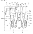
- FIG. 2 is a view depicting the valve actuating mechanism 11 as viewed obliquely from above
- FIG. 3 is a view depicting the valve actuating mechanism 11 as viewed from above.
- the valve actuating mechanism 11 has a camshaft 14 rotatably supported on the cylinder head 5 by bearings.
- a driven sprocket 16 to which rotation is transmitted from the crankshaft by a timing belt 15 is mounted on an axial end of the camshaft 14.
- the camshaft 14 includes a first exhaust cam 17A and a second exhaust cam 17B which are positioned axially adjacent to each other, a first intake cam 18A which is positioned axially outwardly of the first exhaust cam 17A, and a second intake cam 18B which is positioned axially outwardly of the second exhaust cam 17B.
- An intake rocker shaft 19 and an exhaust rocker shaft 20 are disposed parallel to the camshaft 14 on the cylinder head 5.
- An intake first rocker arm 21A and an intake second rocker arm 21B are angularly movably supported on the intake rocker shaft 19.
- An exhaust first rocker arm 22A and an exhaust second rocker arm 22B are angularly movably supported on the exhaust rocker shaft 20.
- the valve actuating mechanism 11 is made up of the camshaft 14, the first and second intake cams 18A and 18B and the first and second exhaust cams 17A and 17B on the camshaft 14, and the intake first and second rocker arms 21A and 21B and the exhaust first and second rocker arms 22A and 22B which are held in abutting engagement with the first and second intake cams 18A and 18B and the first and second exhaust cams 17A and 17B.
- the intake first rocker arm 21A opens and closes the first intake valve 9A under pushing forces received from the first intake cam 18A
- the intake second rocker arm 21B opens and closes the second intake valve 9B under pushing forces received from the second intake cam 18B.
- the exhaust first rocker arm 22A opens and closes the first exhaust valve 10A under pushing forces received from the first exhaust cam 17A
- the exhaust second rocker arm 22B opens and closes the second exhaust valve 10B under pushing forces received from the second exhaust cam 17B.
- the exhaust first rocker arm 22A and the exhaust second rocker arm 22B have respective rocker arm bodies 22A-a and 22B-a formed as castings which are of a substantially triangular shape as viewed in side elevation.
- the rocker arm bodies 22A-a and 22B-a have on corners thereof bosses 23 that are rotatably supported on the exhaust rocker shaft 20, and on other corners thereof roller holders 26 that hold rollers 24 which bear pressing forces from the corresponding exhaust cams (the first exhaust cam 17A and the second exhaust cam 17B).
- the rocker arm bodies 22A-a and 22B-a have on remaining corners thereof valve actuators 25 held in abutting engagement with the ends of the corresponding exhaust valves (the first exhaust valve 10A and the second exhaust valve 10B).
- the camshaft 14 is provided with a decompression mechanism 28 for reducing the compression pressure in the combustion chamber 4 by depressing the first exhaust valve 10A in a valve opening direction the timing of a compression stroke when the internal combustion engine 1 starts to operate.
- the decompression mechanism 28 includes a plunger 29 as a decompression operator which is projectably and retractably mounted on the camshaft 14 at a position adjacent to the first exhaust cam 17A, a decompression shaft 30 rotatably held by the camshaft 14 for projecting or retracting the plunger 29 depending on the angle through which the decompression shaft 30 is turned, a return spring, not depicted, for normally biasing the decompression shaft 30 to turn in a direction to project the plunger 29, and a decompression weight 31 rotatable in unison with the camshaft 14 for turning the decompression shaft 30 in a direction to retract the plunger 29 under centrifugal forces.
- a plunger 29 as a decompression operator which is projectably and retractably mounted on the camshaft 14 at a position adjacent to the first exhaust cam 17A
- a decompression shaft 30 rotatably held by the camshaft 14 for projecting or retracting the plunger 29 depending on the angle through which the decompression shaft 30 is turned
- the plunger 29 of the decompression mechanism 28 can project radially outwardly at a position corresponding to a base-circle portion 17A-a of the first exhaust cam 17A.
- the plunger 29 has a tip end 29a that can project radially outwardly from the camshaft 14 into abutment against the roller 24 on the first rocker arm 22A.
- FIG. 4 is a view depicting the way in which the plunger 29 and the first rocker arm 22A behave when the rotational speed of the camshaft 14 acting on the decompression weight 31 is lower than a prescribed rotational speed.
- FIG. 5 is a view depicting the way in which the plunger 29 and the first rocker arm 22A behave when the rotational speed of the camshaft 14 acting on the decompression weight 31 is equal to or higher than the prescribed rotational speed.
- the prescribed rotational speed is essentially set to the cranking speed of the internal combustion engine.
- FIGS. 6 and 7 are views depicting the exhaust first rocker arm 22A and the exhaust second rocker arm 22B, respectively, as viewed obliquely from above.
- the rocker arm bodies 22A-a and 22B-a of the first rocker arm 22A and the second rocker arm 22B as they are installed on the exhaust rocker shaft 20 are curved so that their bosses 23 and roller holders 26 have proximity portions positioned closest to each other and their valve actuators 25 are spaced away from each other toward extended ends.
- protrusions 22A-b and 22B-b are provided in confronting relation to each other in the vicinity of the roller holders 26 on mutually facing side surfaces of the rocker arm bodies 22A-a and 22B-a.
- the protrusions 22A-b and 22B-b project to such a height that they axially overlap each other.
- FIG. 8 is a cross-sectional view taken along line VIII-VIII of FIG. 3 .
- the protrusion 22A-b of the first rocker arm 22A and the protrusion 22B-b of the second rocker arm 22B have a first abutting surface 33 and a second abutting surface 34, respectively, which can abut against each other.
- the first abutting surface 33 is formed so that when the first rocker arm 22A is turned in a valve opening direction (a direction to open the first exhaust valve 10A), the first abutting surface 33 is oriented toward the valve opening direction.
- the second abutting surface 34 is formed so that when the first rocker arm 22A is turned in the valve opening direction (the direction to open the first exhaust valve 10A), the second abutting surface 34 confronts the first abutting surface 33 of the first rocker arm 22A head on.
- the pair of protrusions 22A-b and 22B-b make up an angular movement transmitter 40 for transmitting the turning force in the valve opening direction from the first rocker arm 22A to the second rocker arm 22B.
- the first abutting surface 33 is formed flatwise, whereas the second abutting surface 34 is formed as an arcuate surface which is curved so as to be centrally projected.
- the second abutting surface 34 may be formed flatwise, whereas the first abutting surface 33 may be formed as an arcuate surface.
- both the first abutting surface 33 and the second abutting surface 34 may be arcuate surfaces.
- a clearance C is kept between the first abutting surface 33 and the second abutting surface 34 when the plunger 29 is retracted (when the decompression operator is not in operation).
- the protrusion 22A-b of the first rocker arm 22A and the protrusion 22B-b of the second rocker arm 22B have respective proximal ends joined to the rocker arm bodies 22A-a and 22B-a, respectively, by progressively spreading arcuate surfaces 36.
- the angular movement transmitter 40 is provided between the first rocker arm 22A and the second rocker arm 22B, and the turning force produced by the plunger 29 of the decompression mechanism 28 in the valve opening direction is transmitted from the first rocker arm 22A to the second rocker arm 22B by the angular movement transmitter 40. Consequently, the first rocker arm 22A and the second rocker arm 22B are constructed as respective independent members, and the second rocker arm 22B is ganged with the first rocker arm 22A in operation only when the decompression process is performed by the decompression mechanism 28.
- the first rocker arm 22A and the second rocker arm 22B can be positioned independently of each other in a layout with a high degree of freedom, and can be of a simple structure that is less susceptible to twisting and vibration without involving an increase in their thickness. Therefore, the structure of the internal combustion engine 1 makes it possible to reduce the weight of the overall valve actuating mechanism 11 by avoiding an increase in the thickness of the first rocker arm 22A and the second rocker arm 22B.
- the angular movement transmitter 40 includes the pair of protrusions 22A-b and 22B-b projecting toward each other from the respective rocker arm bodies 22A-a and 22B-a of the first rocker arm 22A and the second rocker arm 22B and abutting against each other when the first rocker arm 22A is turned in the valve opening direction by the plunger 29 of the decompression mechanism 28.
- the respective rocker arm bodies 22A-a and 22B-a of the first rocker arm 22A and the second rocker arm 22B do not need to be enlarged, but the decompression force from the plunger 29 can be transmitted from the first rocker arm 22A to the second rocker arm 22B by abutting engagement between the protrusions 22A-b and 22B-b. Consequently, this structure described above makes it possible to reduce the size and weight of the valve actuating mechanism 11.
- the pair of protrusions 22A-b and 22B-b that make up the angular movement transmitter 40 are disposed on the closest portions of the mutually facing surfaces of the rocker arm body 22A-a of the first rocker arm 22A and the rocker arm body 22B-a of the second rocker arm 22B. Therefore, in the internal combustion engine 1 according to the present embodiment, the protruding lengths of the protrusions 22A-b and 22B-b can be shortened to reduce a load imposed on the protrusions 22A-b and 22B-b when the decompression process is performed by the plunger 29.
- the proximal ends of the protrusions 22A-b and 22B-b projecting from the first rocker arm 22A and the second rocker arm 22B are joined to the rocker arm bodies 22A-a and 22B-a, respectively, by the progressively spreading contiguous arcuate surfaces 36.
- the rigidity between the proximal ends of the protrusions 22A-b and 22B-b and the rocker arm bodies 22A-a and 22B-a is increased by the progressively spreading contiguous arcuate surfaces 36, making it possible to quickly transmit the decompression force produced by the plunger 29 to the second rocker arm 22B.
- the angular movement transmitter 40 has the first abutting surface 33 of the first rocker arm 22A and the second abutting surface 34 of the second rocker arm 22B, and when the plunger 29 of the decompression mechanism 28 is retracted, the clearance C is created between the first abutting surface 33 and the second abutting surface 34. Therefore, while the internal combustion engine 1 is in normal operation, the first abutting surface 33 and the second abutting surface 34 are held out of contact with each other.
- the roller 24 on the second rocker arm 22B is prevented from being temporarily spaced from and then abutting against the cam surface of the second exhaust cam 17B, producing abutment sounds, and the roller 24 and the cam surface of the second exhaust cam 17B are prevented in advance from being unduly worn by a repetition of abutment and separation between the roller 24 and the second exhaust cam 17B.
- the protrusion 22A-b of the first rocker arm 22A and the protrusion 22B-b of the second rocker arm 22B have the first abutting surface 33 and the second abutting surface 34, respectively, which abut against each other in the decompression process, and at least one of the first abutting surface 33 and the second abutting surface 34 is an arcuate surface curved so as to be projected toward the confronting member.
- the present invention is not limited to the above embodiment, but it is possible to make various design changes to the embodiment without departing from the scope of the invention.
- the angular movement transmitter may be of any of other structures such as in the form of a combination of a protrusion and a recess or the like insofar as they are capable of transmitting angular movement forces through mutual abutment thereof.
- the decompression mechanism is not limited to a structure wherein a plunger is projectable and retractable in radial directions of a camshaft, but may be of any of other structures insofar as the decompression operator lifts the first exhaust cam when the internal combustion engine starts to operate.
- An internal combustion engine includes a camshaft 14 having a first exhaust cam 17A and a second exhaust cam 17B, a first exhaust valve 10A, and a second exhaust valve 10B.
- the internal combustion engine further includes a first rocker arm 22A for actuating the first exhaust valve 10A to open and close, a second rocker arm 22B for actuating the second exhaust valve 10B to open and close, and a decompression mechanism 28 for lifting the first rocker arm 22A in a valve opening direction at the timing of a compression stroke initiated by the internal combustion engine.
- the first rocker arm 22A and the second rocker arm 22B are provided with an angular movement transmitter 40 for transmitting a turning force produced by a decompression operator in the valve opening direction from the first rocker arm 22A to the second rocker arm 22B.
Landscapes
- Engineering & Computer Science (AREA)
- Mechanical Engineering (AREA)
- General Engineering & Computer Science (AREA)
- Chemical & Material Sciences (AREA)
- Combustion & Propulsion (AREA)
- Valve Device For Special Equipments (AREA)
- Valve-Gear Or Valve Arrangements (AREA)
Applications Claiming Priority (1)
| Application Number | Priority Date | Filing Date | Title |
|---|---|---|---|
| JP2015192719A JP6222708B2 (ja) | 2015-09-30 | 2015-09-30 | 内燃機関 |
Publications (2)
| Publication Number | Publication Date |
|---|---|
| EP3150809A1 true EP3150809A1 (fr) | 2017-04-05 |
| EP3150809B1 EP3150809B1 (fr) | 2019-07-03 |
Family
ID=56609741
Family Applications (1)
| Application Number | Title | Priority Date | Filing Date |
|---|---|---|---|
| EP16182972.6A Active EP3150809B1 (fr) | 2015-09-30 | 2016-08-05 | Moteur à combustion interne |
Country Status (4)
| Country | Link |
|---|---|
| US (1) | US9988953B2 (fr) |
| EP (1) | EP3150809B1 (fr) |
| JP (1) | JP6222708B2 (fr) |
| AU (1) | AU2016210687B2 (fr) |
Cited By (2)
| Publication number | Priority date | Publication date | Assignee | Title |
|---|---|---|---|---|
| EP3447259A4 (fr) * | 2016-10-20 | 2019-08-07 | Mitsubishi Heavy Industries Engine & Turbocharger, Ltd. | Culbuteur |
| CN110735684A (zh) * | 2018-07-18 | 2020-01-31 | 本田技研工业株式会社 | 内燃机 |
Families Citing this family (4)
| Publication number | Priority date | Publication date | Assignee | Title |
|---|---|---|---|---|
| KR102664741B1 (ko) * | 2018-10-05 | 2024-05-10 | 제임스 도메닉 크라잔시취 | 개선된 연소 엔진 |
| CN109488412A (zh) * | 2018-11-22 | 2019-03-19 | 陈朝鹏 | 发动机节油减排系统 |
| EA202092392A2 (ru) * | 2020-07-16 | 2022-01-31 | Пауэрхаус Энджин Солюшнз Свитселанд АйПи Холдинг ГмбХ | Система двигателя внутреннего сгорания |
| CN114320517B (zh) * | 2022-01-05 | 2022-09-27 | 浙江钱江摩托股份有限公司 | 一种减压机构 |
Citations (3)
| Publication number | Priority date | Publication date | Assignee | Title |
|---|---|---|---|---|
| JP2008019845A (ja) | 2006-07-14 | 2008-01-31 | Honda Motor Co Ltd | 内燃機関のデコンプ装置 |
| CN202125328U (zh) * | 2011-07-01 | 2012-01-25 | 山东亚翔动力有限公司 | 一种摩托车用减压装置 |
| US20120266836A1 (en) * | 2011-04-25 | 2012-10-25 | GM Global Technology Operations LLC | Rocker arm assembly for internal combustion engine |
Family Cites Families (6)
| Publication number | Priority date | Publication date | Assignee | Title |
|---|---|---|---|---|
| JPS6131610A (ja) * | 1984-07-24 | 1986-02-14 | Honda Motor Co Ltd | 内燃機関の弁作動休止装置 |
| JPS637208U (fr) * | 1986-06-30 | 1988-01-18 | ||
| JP2000282818A (ja) * | 1999-03-31 | 2000-10-10 | Nissan Diesel Motor Co Ltd | 内燃機関の動弁機構 |
| JP2004225662A (ja) * | 2003-01-27 | 2004-08-12 | Toyota Motor Corp | バルブ特性変更機構を有する内燃機関 |
| JP2008082297A (ja) * | 2006-09-28 | 2008-04-10 | Honda Motor Co Ltd | 内燃機関のデコンプ装置 |
| JP6005382B2 (ja) * | 2012-03-30 | 2016-10-12 | 本田技研工業株式会社 | 内燃機関の可変動弁装置 |
-
2015
- 2015-09-30 JP JP2015192719A patent/JP6222708B2/ja not_active Expired - Fee Related
-
2016
- 2016-08-04 AU AU2016210687A patent/AU2016210687B2/en not_active Ceased
- 2016-08-05 EP EP16182972.6A patent/EP3150809B1/fr active Active
- 2016-09-26 US US15/275,814 patent/US9988953B2/en active Active
Patent Citations (3)
| Publication number | Priority date | Publication date | Assignee | Title |
|---|---|---|---|---|
| JP2008019845A (ja) | 2006-07-14 | 2008-01-31 | Honda Motor Co Ltd | 内燃機関のデコンプ装置 |
| US20120266836A1 (en) * | 2011-04-25 | 2012-10-25 | GM Global Technology Operations LLC | Rocker arm assembly for internal combustion engine |
| CN202125328U (zh) * | 2011-07-01 | 2012-01-25 | 山东亚翔动力有限公司 | 一种摩托车用减压装置 |
Cited By (3)
| Publication number | Priority date | Publication date | Assignee | Title |
|---|---|---|---|---|
| EP3447259A4 (fr) * | 2016-10-20 | 2019-08-07 | Mitsubishi Heavy Industries Engine & Turbocharger, Ltd. | Culbuteur |
| US11131219B2 (en) | 2016-10-20 | 2021-09-28 | Mitsubishi Heavy Industries Engine & Turbocharger, Ltd. | Rocker arm |
| CN110735684A (zh) * | 2018-07-18 | 2020-01-31 | 本田技研工业株式会社 | 内燃机 |
Also Published As
| Publication number | Publication date |
|---|---|
| AU2016210687A1 (en) | 2017-04-13 |
| EP3150809B1 (fr) | 2019-07-03 |
| AU2016210687B2 (en) | 2018-05-10 |
| JP6222708B2 (ja) | 2017-11-01 |
| US9988953B2 (en) | 2018-06-05 |
| JP2017066961A (ja) | 2017-04-06 |
| US20170089231A1 (en) | 2017-03-30 |
Similar Documents
| Publication | Publication Date | Title |
|---|---|---|
| EP3150809B1 (fr) | Moteur à combustion interne | |
| US9212574B2 (en) | Valve operating system for internal combustion engine | |
| US9441510B2 (en) | Valve system for a multi-cylinder engine | |
| KR20120110052A (ko) | 캠 구조 | |
| JP6331926B2 (ja) | 内燃機関の可変動弁装置 | |
| CN103306767B (zh) | 用于内燃机的气门机构和内燃机 | |
| KR102454349B1 (ko) | 스위칭 로커 암 | |
| JP5907089B2 (ja) | エンジンの動弁装置 | |
| CN101545387A (zh) | 用于内燃机的可变阀操作系统 | |
| CN108699924B (zh) | 用于致动内燃发动机中的至少一个气门的装置和内燃发动机 | |
| CA2451944A1 (fr) | Moteur a combustion interne | |
| KR101575148B1 (ko) | 가변동 밸브 장치 | |
| CN101501327A (zh) | 机械式压力和真空释放机构 | |
| US8794204B2 (en) | Valvetrain for overhead valve engine | |
| US9429049B2 (en) | Intake valve actuation system for dual fuel engine | |
| JP2014163315A (ja) | エンジンの動弁装置 | |
| JP6400319B2 (ja) | 内燃機関の動弁機構用のカム | |
| KR101646133B1 (ko) | 실린더 휴지 엔진 | |
| JP2015183530A (ja) | エンジンの動弁装置 | |
| JP6325950B2 (ja) | 内燃機関 | |
| JP2006220121A (ja) | 内燃機関のシリンダヘッド | |
| JP2016125354A (ja) | 内燃機関の可変動弁装置 | |
| KR20160057761A (ko) | 가변 밸브 리프트 장치 | |
| JPH07119427A (ja) | デコンプ装置 | |
| CN105637187A (zh) | 内燃机的可变气门装置 |
Legal Events
| Date | Code | Title | Description |
|---|---|---|---|
| PUAI | Public reference made under article 153(3) epc to a published international application that has entered the european phase |
Free format text: ORIGINAL CODE: 0009012 |
|
| STAA | Information on the status of an ep patent application or granted ep patent |
Free format text: STATUS: REQUEST FOR EXAMINATION WAS MADE |
|
| 17P | Request for examination filed |
Effective date: 20160805 |
|
| AK | Designated contracting states |
Kind code of ref document: A1 Designated state(s): AL AT BE BG CH CY CZ DE DK EE ES FI FR GB GR HR HU IE IS IT LI LT LU LV MC MK MT NL NO PL PT RO RS SE SI SK SM TR |
|
| AX | Request for extension of the european patent |
Extension state: BA ME |
|
| GRAP | Despatch of communication of intention to grant a patent |
Free format text: ORIGINAL CODE: EPIDOSNIGR1 |
|
| STAA | Information on the status of an ep patent application or granted ep patent |
Free format text: STATUS: GRANT OF PATENT IS INTENDED |
|
| INTG | Intention to grant announced |
Effective date: 20190124 |
|
| GRAS | Grant fee paid |
Free format text: ORIGINAL CODE: EPIDOSNIGR3 |
|
| GRAA | (expected) grant |
Free format text: ORIGINAL CODE: 0009210 |
|
| STAA | Information on the status of an ep patent application or granted ep patent |
Free format text: STATUS: THE PATENT HAS BEEN GRANTED |
|
| AK | Designated contracting states |
Kind code of ref document: B1 Designated state(s): AL AT BE BG CH CY CZ DE DK EE ES FI FR GB GR HR HU IE IS IT LI LT LU LV MC MK MT NL NO PL PT RO RS SE SI SK SM TR |
|
| REG | Reference to a national code |
Ref country code: GB Ref legal event code: FG4D |
|
| REG | Reference to a national code |
Ref country code: CH Ref legal event code: EP Ref country code: AT Ref legal event code: REF Ref document number: 1151256 Country of ref document: AT Kind code of ref document: T Effective date: 20190715 |
|
| REG | Reference to a national code |
Ref country code: IE Ref legal event code: FG4D |
|
| REG | Reference to a national code |
Ref country code: DE Ref legal event code: R096 Ref document number: 602016016176 Country of ref document: DE |
|
| PGFP | Annual fee paid to national office [announced via postgrant information from national office to epo] |
Ref country code: FR Payment date: 20190822 Year of fee payment: 4 |
|
| REG | Reference to a national code |
Ref country code: NL Ref legal event code: MP Effective date: 20190703 |
|
| REG | Reference to a national code |
Ref country code: LT Ref legal event code: MG4D |
|
| REG | Reference to a national code |
Ref country code: AT Ref legal event code: MK05 Ref document number: 1151256 Country of ref document: AT Kind code of ref document: T Effective date: 20190703 |
|
| PG25 | Lapsed in a contracting state [announced via postgrant information from national office to epo] |
Ref country code: FI Free format text: LAPSE BECAUSE OF FAILURE TO SUBMIT A TRANSLATION OF THE DESCRIPTION OR TO PAY THE FEE WITHIN THE PRESCRIBED TIME-LIMIT Effective date: 20190703 Ref country code: HR Free format text: LAPSE BECAUSE OF FAILURE TO SUBMIT A TRANSLATION OF THE DESCRIPTION OR TO PAY THE FEE WITHIN THE PRESCRIBED TIME-LIMIT Effective date: 20190703 Ref country code: SE Free format text: LAPSE BECAUSE OF FAILURE TO SUBMIT A TRANSLATION OF THE DESCRIPTION OR TO PAY THE FEE WITHIN THE PRESCRIBED TIME-LIMIT Effective date: 20190703 Ref country code: NO Free format text: LAPSE BECAUSE OF FAILURE TO SUBMIT A TRANSLATION OF THE DESCRIPTION OR TO PAY THE FEE WITHIN THE PRESCRIBED TIME-LIMIT Effective date: 20191003 Ref country code: AT Free format text: LAPSE BECAUSE OF FAILURE TO SUBMIT A TRANSLATION OF THE DESCRIPTION OR TO PAY THE FEE WITHIN THE PRESCRIBED TIME-LIMIT Effective date: 20190703 Ref country code: LT Free format text: LAPSE BECAUSE OF FAILURE TO SUBMIT A TRANSLATION OF THE DESCRIPTION OR TO PAY THE FEE WITHIN THE PRESCRIBED TIME-LIMIT Effective date: 20190703 Ref country code: NL Free format text: LAPSE BECAUSE OF FAILURE TO SUBMIT A TRANSLATION OF THE DESCRIPTION OR TO PAY THE FEE WITHIN THE PRESCRIBED TIME-LIMIT Effective date: 20190703 Ref country code: PT Free format text: LAPSE BECAUSE OF FAILURE TO SUBMIT A TRANSLATION OF THE DESCRIPTION OR TO PAY THE FEE WITHIN THE PRESCRIBED TIME-LIMIT Effective date: 20191104 Ref country code: CZ Free format text: LAPSE BECAUSE OF FAILURE TO SUBMIT A TRANSLATION OF THE DESCRIPTION OR TO PAY THE FEE WITHIN THE PRESCRIBED TIME-LIMIT Effective date: 20190703 Ref country code: BG Free format text: LAPSE BECAUSE OF FAILURE TO SUBMIT A TRANSLATION OF THE DESCRIPTION OR TO PAY THE FEE WITHIN THE PRESCRIBED TIME-LIMIT Effective date: 20191003 |
|
| PG25 | Lapsed in a contracting state [announced via postgrant information from national office to epo] |
Ref country code: ES Free format text: LAPSE BECAUSE OF FAILURE TO SUBMIT A TRANSLATION OF THE DESCRIPTION OR TO PAY THE FEE WITHIN THE PRESCRIBED TIME-LIMIT Effective date: 20190703 Ref country code: GR Free format text: LAPSE BECAUSE OF FAILURE TO SUBMIT A TRANSLATION OF THE DESCRIPTION OR TO PAY THE FEE WITHIN THE PRESCRIBED TIME-LIMIT Effective date: 20191004 Ref country code: LV Free format text: LAPSE BECAUSE OF FAILURE TO SUBMIT A TRANSLATION OF THE DESCRIPTION OR TO PAY THE FEE WITHIN THE PRESCRIBED TIME-LIMIT Effective date: 20190703 Ref country code: AL Free format text: LAPSE BECAUSE OF FAILURE TO SUBMIT A TRANSLATION OF THE DESCRIPTION OR TO PAY THE FEE WITHIN THE PRESCRIBED TIME-LIMIT Effective date: 20190703 Ref country code: RS Free format text: LAPSE BECAUSE OF FAILURE TO SUBMIT A TRANSLATION OF THE DESCRIPTION OR TO PAY THE FEE WITHIN THE PRESCRIBED TIME-LIMIT Effective date: 20190703 Ref country code: IS Free format text: LAPSE BECAUSE OF FAILURE TO SUBMIT A TRANSLATION OF THE DESCRIPTION OR TO PAY THE FEE WITHIN THE PRESCRIBED TIME-LIMIT Effective date: 20191103 |
|
| PG25 | Lapsed in a contracting state [announced via postgrant information from national office to epo] |
Ref country code: TR Free format text: LAPSE BECAUSE OF FAILURE TO SUBMIT A TRANSLATION OF THE DESCRIPTION OR TO PAY THE FEE WITHIN THE PRESCRIBED TIME-LIMIT Effective date: 20190703 |
|
| PG25 | Lapsed in a contracting state [announced via postgrant information from national office to epo] |
Ref country code: EE Free format text: LAPSE BECAUSE OF FAILURE TO SUBMIT A TRANSLATION OF THE DESCRIPTION OR TO PAY THE FEE WITHIN THE PRESCRIBED TIME-LIMIT Effective date: 20190703 Ref country code: RO Free format text: LAPSE BECAUSE OF FAILURE TO SUBMIT A TRANSLATION OF THE DESCRIPTION OR TO PAY THE FEE WITHIN THE PRESCRIBED TIME-LIMIT Effective date: 20190703 Ref country code: PL Free format text: LAPSE BECAUSE OF FAILURE TO SUBMIT A TRANSLATION OF THE DESCRIPTION OR TO PAY THE FEE WITHIN THE PRESCRIBED TIME-LIMIT Effective date: 20190703 Ref country code: DK Free format text: LAPSE BECAUSE OF FAILURE TO SUBMIT A TRANSLATION OF THE DESCRIPTION OR TO PAY THE FEE WITHIN THE PRESCRIBED TIME-LIMIT Effective date: 20190703 |
|
| PG25 | Lapsed in a contracting state [announced via postgrant information from national office to epo] |
Ref country code: SK Free format text: LAPSE BECAUSE OF FAILURE TO SUBMIT A TRANSLATION OF THE DESCRIPTION OR TO PAY THE FEE WITHIN THE PRESCRIBED TIME-LIMIT Effective date: 20190703 Ref country code: CH Free format text: LAPSE BECAUSE OF NON-PAYMENT OF DUE FEES Effective date: 20190831 Ref country code: LU Free format text: LAPSE BECAUSE OF NON-PAYMENT OF DUE FEES Effective date: 20190805 Ref country code: IS Free format text: LAPSE BECAUSE OF FAILURE TO SUBMIT A TRANSLATION OF THE DESCRIPTION OR TO PAY THE FEE WITHIN THE PRESCRIBED TIME-LIMIT Effective date: 20200224 Ref country code: SM Free format text: LAPSE BECAUSE OF FAILURE TO SUBMIT A TRANSLATION OF THE DESCRIPTION OR TO PAY THE FEE WITHIN THE PRESCRIBED TIME-LIMIT Effective date: 20190703 Ref country code: MC Free format text: LAPSE BECAUSE OF FAILURE TO SUBMIT A TRANSLATION OF THE DESCRIPTION OR TO PAY THE FEE WITHIN THE PRESCRIBED TIME-LIMIT Effective date: 20190703 Ref country code: LI Free format text: LAPSE BECAUSE OF NON-PAYMENT OF DUE FEES Effective date: 20190831 |
|
| REG | Reference to a national code |
Ref country code: BE Ref legal event code: MM Effective date: 20190831 |
|
| REG | Reference to a national code |
Ref country code: DE Ref legal event code: R097 Ref document number: 602016016176 Country of ref document: DE |
|
| PLBE | No opposition filed within time limit |
Free format text: ORIGINAL CODE: 0009261 |
|
| STAA | Information on the status of an ep patent application or granted ep patent |
Free format text: STATUS: NO OPPOSITION FILED WITHIN TIME LIMIT |
|
| PG2D | Information on lapse in contracting state deleted |
Ref country code: IS |
|
| PG25 | Lapsed in a contracting state [announced via postgrant information from national office to epo] |
Ref country code: IE Free format text: LAPSE BECAUSE OF NON-PAYMENT OF DUE FEES Effective date: 20190805 |
|
| 26N | No opposition filed |
Effective date: 20200603 |
|
| PG25 | Lapsed in a contracting state [announced via postgrant information from national office to epo] |
Ref country code: BE Free format text: LAPSE BECAUSE OF NON-PAYMENT OF DUE FEES Effective date: 20190831 Ref country code: SI Free format text: LAPSE BECAUSE OF FAILURE TO SUBMIT A TRANSLATION OF THE DESCRIPTION OR TO PAY THE FEE WITHIN THE PRESCRIBED TIME-LIMIT Effective date: 20190703 |
|
| PGFP | Annual fee paid to national office [announced via postgrant information from national office to epo] |
Ref country code: IT Payment date: 20200826 Year of fee payment: 5 |
|
| GBPC | Gb: european patent ceased through non-payment of renewal fee |
Effective date: 20200805 |
|
| PG25 | Lapsed in a contracting state [announced via postgrant information from national office to epo] |
Ref country code: CY Free format text: LAPSE BECAUSE OF FAILURE TO SUBMIT A TRANSLATION OF THE DESCRIPTION OR TO PAY THE FEE WITHIN THE PRESCRIBED TIME-LIMIT Effective date: 20190703 |
|
| PG25 | Lapsed in a contracting state [announced via postgrant information from national office to epo] |
Ref country code: FR Free format text: LAPSE BECAUSE OF NON-PAYMENT OF DUE FEES Effective date: 20200831 Ref country code: HU Free format text: LAPSE BECAUSE OF FAILURE TO SUBMIT A TRANSLATION OF THE DESCRIPTION OR TO PAY THE FEE WITHIN THE PRESCRIBED TIME-LIMIT; INVALID AB INITIO Effective date: 20160805 Ref country code: MT Free format text: LAPSE BECAUSE OF FAILURE TO SUBMIT A TRANSLATION OF THE DESCRIPTION OR TO PAY THE FEE WITHIN THE PRESCRIBED TIME-LIMIT Effective date: 20190703 |
|
| REG | Reference to a national code |
Ref country code: DE Ref legal event code: R084 Ref document number: 602016016176 Country of ref document: DE |
|
| PG25 | Lapsed in a contracting state [announced via postgrant information from national office to epo] |
Ref country code: GB Free format text: LAPSE BECAUSE OF NON-PAYMENT OF DUE FEES Effective date: 20200805 |
|
| PG25 | Lapsed in a contracting state [announced via postgrant information from national office to epo] |
Ref country code: MK Free format text: LAPSE BECAUSE OF FAILURE TO SUBMIT A TRANSLATION OF THE DESCRIPTION OR TO PAY THE FEE WITHIN THE PRESCRIBED TIME-LIMIT Effective date: 20190703 |
|
| PG25 | Lapsed in a contracting state [announced via postgrant information from national office to epo] |
Ref country code: IT Free format text: LAPSE BECAUSE OF NON-PAYMENT OF DUE FEES Effective date: 20210805 |
|
| PGFP | Annual fee paid to national office [announced via postgrant information from national office to epo] |
Ref country code: DE Payment date: 20250724 Year of fee payment: 10 |