EP3150933B1 - Befeuchtungselement und befeuchter - Google Patents
Befeuchtungselement und befeuchter Download PDFInfo
- Publication number
- EP3150933B1 EP3150933B1 EP14893163.7A EP14893163A EP3150933B1 EP 3150933 B1 EP3150933 B1 EP 3150933B1 EP 14893163 A EP14893163 A EP 14893163A EP 3150933 B1 EP3150933 B1 EP 3150933B1
- Authority
- EP
- European Patent Office
- Prior art keywords
- water
- humidifying
- storing section
- bodies
- diffusing member
- Prior art date
- Legal status (The legal status is an assumption and is not a legal conclusion. Google has not performed a legal analysis and makes no representation as to the accuracy of the status listed.)
- Active
Links
Images




Classifications
-
- F—MECHANICAL ENGINEERING; LIGHTING; HEATING; WEAPONS; BLASTING
- F24—HEATING; RANGES; VENTILATING
- F24F—AIR-CONDITIONING; AIR-HUMIDIFICATION; VENTILATION; USE OF AIR CURRENTS FOR SCREENING
- F24F6/00—Air-humidification, e.g. cooling by humidification
- F24F6/02—Air-humidification, e.g. cooling by humidification by evaporation of water in the air
- F24F6/04—Air-humidification, e.g. cooling by humidification by evaporation of water in the air using stationary unheated wet elements
Definitions
- the present invention relates to a humidifying element and a humidifying apparatus.
- a natural evaporation type As an apparatus that generates the air of a humidifying atmosphere, there are a natural evaporation type, an electric heating type, a water spray type, an ultrasound type, and the like.
- a humidifying ability tends to be small compared with the other types.
- running cost tends to be high compared with the other types.
- water spray type apparatus humidifying efficiency tends to be low and the apparatus tends to be large compared with the other types.
- initial cost tends to be high compared with the other types.
- the life of the apparatus tends to be short and germs in water and fine powder of calcium carbonate tend to scatter.
- the natural evaporation type humidifier is useful for use, in particular, in a place where the natural evaporation type humidifier is operated for a long time.
- the humidifying ability described as the problem above is being improved.
- dripping type as a humidifying system suitable for use for a long time.
- the humidifier of the dripping type tends to be used in humidifying apparatuses for business use such as an air conditioner.
- Patent Literature 1 discloses a method of dropping water from an upper part of a humidifying element through a porous member and a configuration in which the bottom surface of a water tank is formed of the porous member.
- Patent Literature 2 discloses an upper tray including a large number of water injection holes on the bottom surface of a water tank and a configuration in which a sponge-like porous material is provided between the upper tray and a humidifying filter to wash the humidifying filter.
- JP S62 176629 U discloses a humidifying element according to the preamble of claim 1.
- Patent Literature 1 because the bottom surface is formed of the porous member, hard components included in tap water and vaporization residues such as silica and iron rust deposit on the entire bottom surface.
- the porous member is clogged according to the elapse of time and a water passage amount decreases. Therefore, there is a problem in that a humidifying ability is deteriorated.
- the present invention has been devised in view of the above and an object of the present invention is to obtain a humidifying element that can achieve uniform supply of water to a plurality of humidifying bodies and stable water supply for a long period.
- a humidifying element of the present invention includes a plurality of humidifying bodies arranged along a first direction to provide gaps among the humidifying bodies, a diffusing member that extends along the first direction and is in contact with the plurality of humidifying bodies, and a casing that houses the plurality of humidifying bodies and the diffusing member on an inside.
- a water storing section provided above the humidifying bodies to store water is formed in the casing, a plurality of water injection holes are formed on a bottom surface of the water storing section, a cylindrical wall surface extending downward from the water injection hole portion is formed on an outer side of the bottom surface of the water storing section, a distal end of the cylindrical wall surface and the diffusing member are set in contact, and a communication port for causing an inside and an outside of the cylindrical wall surface to communicate is formed in the cylindrical wall surface.
- FIG. 1 is a configuration diagram of a humidifying apparatus 1 according to a first embodiment.
- a humidifying element 2 is incorporated in the humidifying apparatus 1.
- a blower 5 for feeding the air in a room into the humidifying element 2 and blowing out the air into the room is incorporated on a ventilation upstream side or a ventilation downstream side of the humidifying element 2.
- the humidifying apparatus 1 includes the humidifying element 2, a water supply pipe 3 connected to a water supply source such as waterworks to feed water for humidification to the humidifying element 2, a water discharge pipe 4 for discharging the water remaining not used for the humidification by the humidifying element 2 to the outside, the blower 5 that allows an air flow to pass through the humidifying element 2, a control device 6 that performs, for example, control of the blower 5 and an electromagnetic valve of a water supply system (a water supply valve 3a), and a drain pan 7 that receives waste water and discharges the waste water to the outside.
- a water supply pipe 3 connected to a water supply source such as waterworks to feed water for humidification to the humidifying element 2
- a water discharge pipe 4 for discharging the water remaining not used for the humidification by the humidifying element 2 to the outside
- the blower 5 that allows an air flow to pass through the humidifying element 2
- a control device 6 that performs, for example, control of the blower 5 and an electromagnetic valve of a water supply system (
- FIG. 2 is an enlarged view of the portion of the humidifying element 2 of the humidifying apparatus 1.
- One or a plurality of humidifying elements 2 are directly set on the drain pan 7. Corner portions on both sides of top structures of the humidifying elements 2 are insertably and removably held by, for example, guide rails (not shown in the figure) suspended on partition walls and a front side inner wall surface of a main body box body.
- a water supply system including the water supply valve 3a that supplies water for humidification and interrupts the supply is connected to the humidifying elements 2.
- the water discharge pipe 4 is connected to the drain pan 7.
- the water supply system that feeds the water for humidification to the humidifying elements 2 is configured as a water channel including, besides the water supply valve 3a that adjusts the pressure and the flow rate of the water supplied to the humidifying element 2, a strainer that prevents intrusion of dust into the water supply system and the water supply pipe 3 for water feeding. All of connecting portions of the water supply system excluding a connecting portion to the water supply source side are desirably integrated in the drain pan 7.
- FIG. 3 is a perspective view of the humidifying element 2.
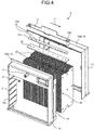
- FIG. 4 is an exploded perspective view of the humidifying element 2.
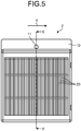
- FIG. 5 is a front view of the humidifying element 2.
- FIG. 6 is an arrow sectional view taken along line X-X shown in FIG. 5 .
- the humidifying element 2 includes a large number of flat humidifying bodies 20 arranged along a first direction (a direction indicated by an arrow Y in FIG. 5 ) to provide gaps among the humidifying bodies 20.
- a diffusing member (a diffusion plate) 30 is set in contact with upper parts of the humidifying bodies 20.
- the diffusing member 30 is formed to extend along the first direction.
- a plurality of humidifying bodies 20 are collectively in contact with one diffusing member 30.
- a water storing section 12 that stores water to be supplied to the humidifying bodies 20 and a water supply port 11 for injecting water supplied from the water supply pipe 3 into the water storing section 12 are present above the humidifying bodies 20.
- a water discharge section 13 and a water discharge port 13a for receiving water remaining without being used for humidification from the humidifying bodies 20 and discharging the water are present below the humidifying bodies 20.
- the humidifying bodies 20 are housed and fixed on the inside of the casing 10.
- the water supply port 11, the water storing section 12, and the water discharge section 13 are formed in the casing 10.
- a structure wall 14 that connects the water storing section 12 serving as an upper structure and the water discharge section 13 serving as a lower structure is formed in the casing 10.
- the casing 10 is formed by, for example, injection molding by thermoplastic such as ABS resin, PS resin, or PP resin.
- the casing 10 is divided into two components, that is, a casing 10a and a casing 10b.
- the casing 10a and the casing 10b are integrated by sandwiching the humidifying bodies 20 with the casing 10a and the casing 10b and joining engaging sections 15 of the casing 10a and the casing 10b.
- portions formed as the water storing section 12 portions formed as the water discharge port 13a, and opening sections 10c for introducing humidified air into the humidifying bodies 20 are respectively provided.
- the water supply port 11 for supplying water to the water storing section 12 is provided in the casing 10b.
- a housing space for housing the humidifying bodies 20 is provided on the inner side of the casing 10.
- Positioning protrusions 17 for regulating the positions of the humidifying bodies 20 are provided in portions of the casing 10 in contact with the humidifying bodies 20.
- the humidifying bodies 20 there are some humidifying bodies that soften when containing water and are deformed by the weight of water. Therefore, by regulating the positions of the humidifying bodies 20 in the outer peripheral portions of the humidifying bodies 20 in contact with the casing 10, it is possible to secure dimensions of channels among the humidifying bodies 20 and allow the air to uniformly flow.
- the water storing section 12 can be formed integrally with the diffusing member 30 and housed in the casing 10.
- the water supply pipe 3 is connected to the water supply port 11 to supply water to the water storing section 12. Therefore, the water supply port 11 is provided further on the upper surface side than the humidifying bodies 20 in an upper part of the humidifying element 2.
- the shape of the water supply port 11 is a shape matching the water supply pipe 3. For example, a convex band (a fold back) can be formed over the circumferential length of the water supply port 11 or the water supply port 11 can be bound by a hose band to prevent the water supply pipe 3 from easily come off.
- a water supply amount is too excessive with respect to a humidifying amount, an amount of water flowing from the water discharge section 13 without being used for humidification is large and a useless water amount increases. Therefore, it is desirable to provide a mechanism for reducing a water amount (e.g., an orifice 21 shown in FIGS. 3 , 4 and 6 ) and adjust a flow rate. In the flow rate adjustment, it is necessary to make it possible to supply a flow rate larger than a maximum humidifying amount of the humidifying element 2.
- the position and the like of the water supply port 11 are not limited as long as the water supply port 11 can supply water from upper parts of the humidifying bodies 20.
- the water storing section 12 is provided above the humidifying bodies 20.
- a plurality of water injection holes 12a are formed on the bottom surface of the water storing section 12.
- a cylindrical wall surface 12b extending downward from the water injection hole 12a portion is formed on the outer side of the water storing section 12.
- a cutout (a communication port) 12c is formed at the distal end of the cylindrical wall surface 12b. The distal end of the cylindrical wall surface 12b is in contact with the diffusing member 30.
- a cylindrical water guide pipe 100 extending up and down is formed in a position avoiding the water injection hole 12a.
- an inflow port for causing water to flow into the inside of the water guide pipe 100 is formed in a position lower than the upper end of the water storing section 12.
- the upper end of the water guide pipe 100 is in a position lower than the upper end of an outer wall of the water storing section 12.
- An opening on the upper end side is the inflow port.
- a tabular water guide member 110 is held between the water storing section 12 and the diffusing member 30.
- the water storing section 12 and the diffusing member 30 are integrally combined.
- An integral component of the water storing section 12 and the diffusing member 30 is sandwiched and held between the casing 10a and the casing 10b.
- a water level sensor 8 for detecting a water level of the water storing section 12 can be set in the water storing section 12. The detected water level can be fed back to control opening and closing of the water supply valve 3a with the control device 6.
- the diffusing member 30 is formed of a porous tabular material.
- the surface of the material is desirably hydrophilic. Permeability is improved by the hydrophilicity and a water supply amount increases.
- the diffusing member 30 comes into contact with water, the diffusing member 30 is desirably formed of a material less easily deteriorated by the water, for example, a porous material made of resin including polyester such as PET resin or PP resin, cellulose, or metal including titanium, copper, or stainless steel. Hydrophilic treatment can be applied to the porous material to increase a hydrophilicity degree of the surface of the material.
- the humidifying bodies 20 are formed of a porous tabular material. Suitable conditions for the humidifying bodies 20 are the same as the conditions for the diffusing member 30. Projecting sections 40 are provided on the surfaces of the humidifying bodies 20. Intervals among the humidifying bodies 20 are maintained by the projecting sections 40. The projecting sections 40 are formed by, for example pressing a jig or the like against the humidifying bodies 20 and plastically deforming pressed portions of the humidifying bodies 20. When two kinds of the humidifying bodies 20, on which arrayed positions of the projecting sections 40 are different, are alternately arrayed, the humidifying bodies 20 have a function of keeping the intervals of the humidifying bodies fixed. The intervals of the humidifying bodies only have to be kept.
- Combs having cutouts equivalent to the humidifying body thickness can be engaged with the humidifying bodies at fixed intervals to maintain the intervals or a structure for keeping intervals by stacking a plurality of wavy humidifying bodies in a honeycomb shape has no problem functionally.
- the lower end of the diffusing member 30 and the upper ends of the humidifying bodies 20 are set partially in contact with each other. If the diffusing member 30 and the humidifying bodies 20 are in contact, water smoothly flows down with the action of surface tension. However, the lower end of the diffusing member 30 and the upper end of the humidifying bodies 20 can be inserted into each other and coupled taking into account the influence of fluctuation during assembly and vibration during transportation.
- a flow of water from the water supply port 11 to the humidifying bodies 20 is explained.
- the water supplied from the water supply port 11 flows into the water storing section 12.
- the water flowed into the water storing section 12 flows from the water injection holes 12a on the bottom surface of the water storing section 12 and runs on the cylindrical wall surface 12b having the cutout 12c to be absorbed by the diffusing member 30.
- the water flows down while spreading to the inside of the diffusing member 30 and reaches the lower end of the diffusing member 30.
- the flowed-down water runs from sections of the contact to the humidifying bodies 20 and flows down with the action of the surface tension.
- the water flows down while spreading to the insides of the humidifying bodies 20 and being contained in the entire humidifying bodies 20 and drips from the lower ends of the humidifying bodies 20.
- moisture is taken from the surface of the humidifying bodies 20 by the air ventilated among the humidifying bodies 20.
- the air is discharged from the humidifying element 2 as humidified air. Therefore, a water amount dripped and discharged from the lower ends of the humidifying bodies 20 is a water amount obtained by subtracting a water amount taken from the humidifying bodies 20 as the humidified air from a water amount supplied from the water supply port 11.
- a and b decrease and the flow rate Q1 of the water flowing in the water injection hole 12a decreases.
- a water supply amount Q of the water supplied from the water supply port 11, time t from a start of the water supply, and a water level change h(t) have the following relation.
- h t Q ⁇ b / a ⁇ 1 ⁇ exp ⁇ a / A ⁇ t
- A represents the bottom area of the water storing section 12.
- the water level h of the water stored in the water storing section 12 is determined such that the flow rate Q1 of the water passing through the water injection hole 12a is equal to the water supply amount Q from the water supply port 11. Therefore, when hard components of the supply water and vaporization residues such as silica and iron rust deposit in the water injection hole 12a as time elapses, a and b decrease. Because the water level h of the water storing section 12 rises according to Expression (3), the flow rate Q1, that is, a humidifying amount is controlled to be fixed.
- the humidifying element 2 that supplies the water from the water storing section 12 provided above the humidifying bodies 20 via the water injection hole 12a and the diffusing member 30 has a function of controlling the humidifying amount to be fixed even when time elapses.
- an allowable upper limit value of a water level rise is present according to the dimensions of the water storing section 12 or the casing 10. From Expression (2), time until the water level reaches a state of a fixed water level increases when a decreases. Therefore, time is required from the start of the water supply until the humidifying amount stabilizes. Such a state is undesirable in the humidifying apparatus. Therefore, it is necessary to prevent the vaporization residues from depositing in the water injection hole 12a as much as possible even when time elapses.
- FIG. 7 is a bottom view of the water storing section 12 viewed from below.
- FIG. 8 is a sectional view of a peripheral portion of the water storing section 12.
- FIG. 9 is a sectional view of a peripheral portion of a water storing section 112 shown as a comparative example.
- a cylindrical wall surface 112b obtained by extending the inner surface of a water injection hole 112a downward is formed at the lower end of the water injection hole 112a.
- a cutout is not formed at the distal end of the cylindrical wall surface 112b.
- the cylindrical wall surface 12b including the cutout 12c opened in a part of the side surface is formed.
- the inside of the cylindrical wall surface 12b is opened to the atmosphere through the cutout 12c. Therefore, even when the air bubbles 91 adhere to the diffusing member 30, the air bubbles 91 touch the atmosphere. Therefore, the air bubbles 91 quickly disappear. As a satisfactory water passage state is easily maintained. It is possible to secure a stable humidifying amount.
- a communication port 18 that causes the outside of the casing 10 and the water storing section 12 to communicate is formed above the water storing section 12. Therefore, the water storing section 12 is opened to the atmosphere. Further, because the communication port 18 is provided above the water supply port 11, the inside of the space of the water storing section 12 is always kept at the atmospheric pressure. The water pressure in the bottom surface portion of the water storing section 12 is the water-gage pressure of the water level. Therefore, it is possible to reduce the influence of fluctuation in supply pressure and secure a fixed humidifying amount.
- a stop of the humidifying operation at the time when humidification is unnecessary such as night is explained.
- the humidifying operation of the humidifying apparatus 1 is sometimes stopped.
- bacteria and mold in the air adhere to a wet portion and propagate, there is concern that the bacteria and mold spores are conveyed by ventilated air passing the surface of the humidifying element 2 and discharged into the room when the humidifying operation is resumed.
- As a method of suppressing the propagation of the bacteria and the mold it is effective to dry the humidifying element 2 as soon as possible.
- FIG. 10 is a sectional view showing an example of a peripheral portion of the water storing section 12.
- the bottom surface of the water storing section 12 inclines to be the lowest in the water injection hole 12a portion. Therefore, after the water supply valve 3a is closed, the water in the water storing section 12 smoothly flows down toward the water injection hole 12a. Therefore, the water in the water storing section 12 easily flows out to the outside through the water injection hole 12a. It is possible to achieve early drying in the water storing section 12.
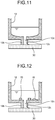
- FIG. 11 is a sectional view showing an example of the peripheral portion of the water storing section 12.
- the bottom surface of the water storing section 12 is formed by a curved surface and inclined to be the bottom in the water injection hole 12a. Note that the bottom surface of the water storing section 12 can be formed by a plane and a curved surface.
- the material of the water storing section 12 can be a water repellent material such as PP or PTFE or, even if the water repellent material is not used, water repellent treatment can be applied to the surface of the water storing section 12 such that the water less easily stay in the water storing section 12. Further, from the viewpoint of hygiene, antibacterial treatment or mold prevention treatment can be applied to the water storing section 12, the diffusing member 30, the humidifying bodies 20, and the casing 10.
- FIG. 12 is a sectional view showing an example of the peripheral portion of the water storing section 12.
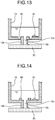
- FIG. 13 is a sectional view showing an example of the peripheral portion of the water storing section 12.
- a projecting section 70 is provided in the bottom of the water storing section 12 to surround the water injection hole 12a.
- a recessed section 80 is provided in the bottom of the water storing section 12 to surround the water injection hole 12a.
- the vaporization residues 16 accumulate and deposit on the bottom surface of the water storing section 12 because the vaporization residues 16 have specific weight larger than the specific weight of water.
- the vaporization residues 16 deposited on the bottom surface also flow toward the diffusing member 30.
- the projecting section 70 is provided in the bottom of the water storing section 12 to surround the water injection hole 12a, the vaporization residues 16 are dammed by the projecting section 70 and suppressed from intruding into the diffusing member 30.
- the recessed section 80 is provided as shown in FIG. 13 , the vaporization residues 16 having the specific weight larger than the specific weight of the water enter the recessed section 80. Therefore, intrusion into the diffusing member 30 is suppressed and the drainage is secured. Note that a part of the recessed section 80 can be fragmented to provide a fragmented portion.
- FIG. 14 is a sectional view showing an example of the peripheral portion of the water storing section 12.
- a capturing member 90 serving as a core of the vaporization residues 16 is provided on the bottom surface of the water storing section 12.
- the vaporization residues 16 in the water grow using components of the capturing member 90 as cores and precipitate and fix on the surface of the capturing member 90. Therefore, it is possible to suppress intrusion of the vaporization residues 16 into the diffusing member 30.
- the capturing member 90 is formed of a material serving as a core of growth of calcium carbide, silica, iron, and the like included in supplied water.
- a substance containing calcium carbide such as calcite or aragonite is suitable for the calcium carbide
- a silica compound such as quartz is suitable for the silica
- a copper material is suitable for the iron.
- the respective components can be separately disposed in the water storing section 12 or can be changed to a powder state, mixed, and equalized and thereafter solidified by a binder or the like and used.
- the material of the water storing section 12 can be a water repellent material such as PP or PTFE or, even if the water repellent material is not used, water repellent treatment can be applied to the surface of the water storing section 12 such that the water less easily stay in the water storing section 12.
- antibacterial treatment or mold prevention treatment is desirably applied to the water storing section 12, the diffusing member 30, the humidifying bodies 20, and the casing 10.
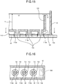
- FIG. 15 is a sectional view showing an example of the peripheral portion of the water storing section 12.
- FIG. 16 is an arrow sectional view taken along line Z-Z shown in FIG. 15 .
- the water guide pipe 100 is indicated by a broken line.
- the cylindrical water guide pipe 100 extending up and down avoiding the water injection holes 12a is formed.
- a water-guide-pipe open hole 12d piercing through the bottom surface of the water storing section 12 is formed.
- a surrounding wall 12e projecting downward to surround the circumference of the water-guide-pipe open hole 12d and the cylindrical wall surfaces 12b is formed.
- a projection amount of the cylindrical wall surfaces 12b and a projection amount of the surrounding wall 12e are equal.
- the distal ends of both of the cylindrical wall surfaces 12b and the surrounding wall 12e are in contact with the diffusing member 30.
- a tabular water guide member 110 formed in size fit in the inner side of the surrounding wall 12e is provided between the water storing section 12 and the diffusing member 30.
- through-holes 110a larger than the outer diameter of the cylindrical wall surfaces 12b are formed in positions corresponding to the water injection holes 12a (positions overlapping the water injection holes 12a in plan view).
- the water guide member 110 is in contact with the diffusing member 30.
- the supply water flowed into the water guide pipe 100 flows on the water guide member 110 and flows down from the through-holes 110a to the diffusing member 30. If the through-holes 110a are adjusted to a proper hole diameter, the supply water is evenly distributed to the through-holes 110a and flows down to the diffusing member 30. According to this action, even when the water injection amount from the water injection holes 12a decreases and the water level h substantially rises, the supply water does not overflow from the water storing section 12. It is possible to uniformly supply the water to the diffusing member 30. When the water guide member 110 is not provided, a lot of the supply water penetrates the diffusing member 30 from a portion right under the water-guide-pipe open hole 12d. Therefore, it is difficult to uniformly supply the water.
- the water guide pipe 100 is formed near the outer wall of the water storing section 12. More specifically, the outer wall is formed to be included in a part of the water guide pipe 100. However, the water guide pipe 100 can be formed in a position away from the outer wall.
- the cutout 12c functioning as the communication port formed at the distal end of the cylindrical wall surface 12b only has to be capable of causing the inside of the cylindrical wall surface 12b to communicate with the outside and allow the air bubbles to escape. Therefore, the communication port can be formed as a hole rather than the cutout. However, because the air bubbles is easily generated on the surface of the diffusing member 30, it is possible to more easily allow the air bubbles to escape by forming the communication port further on the distal end side.
- the humidifying element 2 and the humidifying apparatus 1 configured as explained, it is possible to achieve uniform supply of water to the plurality of humidifying bodies 20. It is possible to achieve stable water supply to the humidifying bodies 20 for a long period. It is possible to simplify the configuration of the humidifying element 2 and achieve facilitation of assemblability. It is possible to achieve an increase in the humidifying amount by the humidifying element 2. It is possible to achieve improvement of hygiene.
Landscapes
- Engineering & Computer Science (AREA)
- Chemical & Material Sciences (AREA)
- Combustion & Propulsion (AREA)
- Mechanical Engineering (AREA)
- General Engineering & Computer Science (AREA)
- Air Humidification (AREA)
Claims (3)
- Befeuchtungselement (2), umfassend:eine Vielzahl von Befeuchtungskörpern (20), die entlang einer ersten Richtung angeordnet sind, um Zwischenräume zwischen den Befeuchtungskörpern (20) bereitzustellen; undein Gehäuse (10), in dem die Vielzahl von Befeuchtungskörpern (20) auf einer Innenseite untergebracht sind, wobeiein Wasserlagerungsabschnitt (12), der oberhalb der Befeuchtungskörper (20) bereitgestellt ist, um Wasser zu lagern, in dem Gehäuse (10) gebildet ist,eine Vielzahl von Wassereinspritzlöchern (12a) auf einer Bodenoberfläche des Wasserlagerungsabschnitts (12) ausgebildet sind,eine zylindrische Wandoberfläche (12b), die sich von dem Abschnitt des Wassereinspritzlochs (12a) nach unten erstreckt, auf einer äußeren Seite der Bodenoberfläche des Wasserlagerungsabschnitts (12) ausgebildet ist,ein distales Ende der zylindrischen Wandoberfläche (12b) und das Diffusionselement (30) in Kontakt gebracht sind, undeine Kommunikationsöffnung (12c) zum Veranlassen einer Innenseite und einer Außenseite der zylindrischen Wandoberfläche (12b), zu kommunizieren, in der zylindrischen Wandoberfläche (12b) ausgebildet ist, wobei das Befeuchtungselement dadurch gekennzeichnet ist, dass es ein Diffusionselement (30) umfasst, das auf der Innenseite des Gehäuses (10) untergebracht ist und sich entlang der ersten Richtung erstreckt und mit der Vielzahl von Befeuchtungskörpern (20) in Kontakt ist,und ferner dadurch gekennzeichnet ist, dass ein distales Ende der zylindrischen Wandoberfläche (12b) und das Diffusionselement (30) in Kontakt gebracht sind.
- Befeuchtungselement nach Anspruch 1, wobei die Kommunikationsöffnung (12c) ein Ausschnitt ist, der am distalen Ende der zylindrischen Wandoberfläche (12b) ausgebildet ist.
- Befeuchtungsvorrichtung (1), umfassend:das Befeuchtungselement (2) nach Anspruch 1 oder 2;undein Gebläse (5), das Luft zwischen den Befeuchtungskörpern (20) passieren lässt.
Applications Claiming Priority (2)
| Application Number | Priority Date | Filing Date | Title |
|---|---|---|---|
| JP2014113150 | 2014-05-30 | ||
| PCT/JP2014/082560 WO2015182014A1 (ja) | 2014-05-30 | 2014-12-09 | 加湿素子および加湿装置 |
Publications (3)
| Publication Number | Publication Date |
|---|---|
| EP3150933A1 EP3150933A1 (de) | 2017-04-05 |
| EP3150933A4 EP3150933A4 (de) | 2018-01-24 |
| EP3150933B1 true EP3150933B1 (de) | 2019-01-30 |
Family
ID=54698380
Family Applications (1)
| Application Number | Title | Priority Date | Filing Date |
|---|---|---|---|
| EP14893163.7A Active EP3150933B1 (de) | 2014-05-30 | 2014-12-09 | Befeuchtungselement und befeuchter |
Country Status (4)
| Country | Link |
|---|---|
| EP (1) | EP3150933B1 (de) |
| JP (1) | JP6038407B2 (de) |
| CN (1) | CN106489053B (de) |
| WO (1) | WO2015182014A1 (de) |
Families Citing this family (1)
| Publication number | Priority date | Publication date | Assignee | Title |
|---|---|---|---|---|
| DE102023123386A1 (de) | 2023-08-30 | 2025-03-06 | Salino GmbH | Luftbefeuchtungseinrichtung |
Family Cites Families (17)
| Publication number | Priority date | Publication date | Assignee | Title |
|---|---|---|---|---|
| SE391576B (sv) * | 1975-03-11 | 1977-02-21 | Svenska Flaektfabriken Ab | Anordning for befuktning av genom en kammare strommande luft |
| JPS62176629U (de) * | 1986-04-30 | 1987-11-10 | ||
| WO1991009256A1 (en) * | 1989-12-08 | 1991-06-27 | Skandinavisk Miljø System A/S | Air humidification apparatus |
| JPH04366336A (ja) * | 1991-06-12 | 1992-12-18 | Taikisha Ltd | 加湿器 |
| JPH08178375A (ja) * | 1994-12-28 | 1996-07-12 | Japan Gore Tex Inc | 加湿装置 |
| US5853625A (en) * | 1997-06-27 | 1998-12-29 | Honeywell Inc. | Water distribution tray for a pad-type humidifier unit |
| US6572085B2 (en) * | 2001-05-15 | 2003-06-03 | Research Products Corporation | Humidifier with reversible housing and distribution tray overflow |
| JP2003130401A (ja) * | 2001-10-23 | 2003-05-08 | Sharp Corp | 加湿装置 |
| JP2003185201A (ja) * | 2001-12-20 | 2003-07-03 | Orion Mach Co Ltd | エアプロセッサ |
| JP4992233B2 (ja) * | 2005-12-02 | 2012-08-08 | パナソニック株式会社 | 加湿装置 |
| JP2009180434A (ja) * | 2008-01-31 | 2009-08-13 | Sharp Corp | 加湿装置 |
| CN201497109U (zh) * | 2009-04-22 | 2010-06-02 | 深圳市联创实业有限公司 | 空气净化加湿机 |
| CN201513996U (zh) * | 2009-09-25 | 2010-06-23 | 上海科绿特环保科技有限公司 | 气候箱露点加湿装置 |
| CN102052725A (zh) * | 2009-11-11 | 2011-05-11 | 田志坚 | 高能效比空气加湿器 |
| CN201652674U (zh) * | 2010-02-23 | 2010-11-24 | 田志坚 | 高效节能空气加湿器 |
| JP2012154547A (ja) * | 2011-01-25 | 2012-08-16 | Zojirushi Corp | 加湿器 |
| US9285133B2 (en) * | 2012-01-21 | 2016-03-15 | Air System Components, Inc. | Air humidification system |
-
2014
- 2014-12-09 JP JP2016523101A patent/JP6038407B2/ja active Active
- 2014-12-09 CN CN201480079354.8A patent/CN106489053B/zh active Active
- 2014-12-09 WO PCT/JP2014/082560 patent/WO2015182014A1/ja not_active Ceased
- 2014-12-09 EP EP14893163.7A patent/EP3150933B1/de active Active
Non-Patent Citations (1)
| Title |
|---|
| None * |
Also Published As
| Publication number | Publication date |
|---|---|
| WO2015182014A1 (ja) | 2015-12-03 |
| EP3150933A4 (de) | 2018-01-24 |
| CN106489053A (zh) | 2017-03-08 |
| JPWO2015182014A1 (ja) | 2017-04-20 |
| CN106489053B (zh) | 2019-05-03 |
| JP6038407B2 (ja) | 2016-12-07 |
| EP3150933A1 (de) | 2017-04-05 |
Similar Documents
| Publication | Publication Date | Title |
|---|---|---|
| US8132534B2 (en) | Overflow device for water tank | |
| EP3128245B1 (de) | Befeuchtungselement und befeuchter | |
| JP6038406B2 (ja) | 加湿素子および加湿装置 | |
| EP3150933A1 (de) | Befeuchtungselement und befeuchter | |
| GB0615297D0 (en) | Upward discharge waste device for a shower tray | |
| JP6169053B2 (ja) | 加湿素子および加湿装置 | |
| JP2015183991A (ja) | 加湿素子および加湿装置 | |
| JP6636148B2 (ja) | 加湿素子、加湿装置、空気調和機および換気装置 | |
| JP2015183992A (ja) | 加湿素子および加湿装置 | |
| JP6742517B2 (ja) | 加湿素子、加湿装置、空気調和機および換気装置 | |
| JP6223285B2 (ja) | 加湿素子および加湿装置 | |
| JP6218688B2 (ja) | 加湿素子および加湿装置 | |
| JP6041757B2 (ja) | 加湿エレメント及び加湿装置 | |
| JP2015183989A (ja) | 加湿素子および加湿装置 | |
| JP2015183990A (ja) | 加湿素子および加湿装置 | |
| JP6453570B2 (ja) | 加湿素子および加湿装置 | |
| JP7236872B2 (ja) | 加湿素子、加湿装置、空気調和機および換気装置 | |
| JP7186648B2 (ja) | 加湿素子、加湿装置、換気装置及び空気調和機 | |
| JP7254048B2 (ja) | 加湿素子、加湿装置、空気調和機および換気装置 | |
| JP3148455U (ja) | 畜舎 | |
| JP2015028399A (ja) | 加湿素子及びそれを備えた加湿装置 | |
| TW200724244A (en) | Immersion type coating method and device |
Legal Events
| Date | Code | Title | Description |
|---|---|---|---|
| STAA | Information on the status of an ep patent application or granted ep patent |
Free format text: STATUS: THE INTERNATIONAL PUBLICATION HAS BEEN MADE |
|
| PUAI | Public reference made under article 153(3) epc to a published international application that has entered the european phase |
Free format text: ORIGINAL CODE: 0009012 |
|
| STAA | Information on the status of an ep patent application or granted ep patent |
Free format text: STATUS: REQUEST FOR EXAMINATION WAS MADE |
|
| 17P | Request for examination filed |
Effective date: 20161208 |
|
| AK | Designated contracting states |
Kind code of ref document: A1 Designated state(s): AL AT BE BG CH CY CZ DE DK EE ES FI FR GB GR HR HU IE IS IT LI LT LU LV MC MK MT NL NO PL PT RO RS SE SI SK SM TR |
|
| AX | Request for extension of the european patent |
Extension state: BA ME |
|
| RIN1 | Information on inventor provided before grant (corrected) |
Inventor name: KAMEISHI, KEIJI Inventor name: HIRAI, HIDEKAZU |
|
| DAX | Request for extension of the european patent (deleted) | ||
| A4 | Supplementary search report drawn up and despatched |
Effective date: 20171222 |
|
| RIC1 | Information provided on ipc code assigned before grant |
Ipc: F24F 6/04 20060101AFI20171218BHEP |
|
| REG | Reference to a national code |
Ref country code: DE Ref legal event code: R079 Ref document number: 602014040628 Country of ref document: DE Free format text: PREVIOUS MAIN CLASS: F24F0006000000 Ipc: F24F0006040000 |
|
| GRAP | Despatch of communication of intention to grant a patent |
Free format text: ORIGINAL CODE: EPIDOSNIGR1 |
|
| STAA | Information on the status of an ep patent application or granted ep patent |
Free format text: STATUS: GRANT OF PATENT IS INTENDED |
|
| RIC1 | Information provided on ipc code assigned before grant |
Ipc: F24F 6/04 20060101AFI20180717BHEP |
|
| INTG | Intention to grant announced |
Effective date: 20180808 |
|
| GRAS | Grant fee paid |
Free format text: ORIGINAL CODE: EPIDOSNIGR3 |
|
| GRAA | (expected) grant |
Free format text: ORIGINAL CODE: 0009210 |
|
| STAA | Information on the status of an ep patent application or granted ep patent |
Free format text: STATUS: THE PATENT HAS BEEN GRANTED |
|
| AK | Designated contracting states |
Kind code of ref document: B1 Designated state(s): AL AT BE BG CH CY CZ DE DK EE ES FI FR GB GR HR HU IE IS IT LI LT LU LV MC MK MT NL NO PL PT RO RS SE SI SK SM TR |
|
| REG | Reference to a national code |
Ref country code: GB Ref legal event code: FG4D |
|
| REG | Reference to a national code |
Ref country code: CH Ref legal event code: EP |
|
| REG | Reference to a national code |
Ref country code: AT Ref legal event code: REF Ref document number: 1093597 Country of ref document: AT Kind code of ref document: T Effective date: 20190215 |
|
| REG | Reference to a national code |
Ref country code: IE Ref legal event code: FG4D |
|
| REG | Reference to a national code |
Ref country code: DE Ref legal event code: R096 Ref document number: 602014040628 Country of ref document: DE |
|
| REG | Reference to a national code |
Ref country code: LT Ref legal event code: MG4D |
|
| REG | Reference to a national code |
Ref country code: NL Ref legal event code: MP Effective date: 20190130 |
|
| PG25 | Lapsed in a contracting state [announced via postgrant information from national office to epo] |
Ref country code: NO Free format text: LAPSE BECAUSE OF FAILURE TO SUBMIT A TRANSLATION OF THE DESCRIPTION OR TO PAY THE FEE WITHIN THE PRESCRIBED TIME-LIMIT Effective date: 20190430 Ref country code: FI Free format text: LAPSE BECAUSE OF FAILURE TO SUBMIT A TRANSLATION OF THE DESCRIPTION OR TO PAY THE FEE WITHIN THE PRESCRIBED TIME-LIMIT Effective date: 20190130 Ref country code: LT Free format text: LAPSE BECAUSE OF FAILURE TO SUBMIT A TRANSLATION OF THE DESCRIPTION OR TO PAY THE FEE WITHIN THE PRESCRIBED TIME-LIMIT Effective date: 20190130 Ref country code: PL Free format text: LAPSE BECAUSE OF FAILURE TO SUBMIT A TRANSLATION OF THE DESCRIPTION OR TO PAY THE FEE WITHIN THE PRESCRIBED TIME-LIMIT Effective date: 20190130 Ref country code: PT Free format text: LAPSE BECAUSE OF FAILURE TO SUBMIT A TRANSLATION OF THE DESCRIPTION OR TO PAY THE FEE WITHIN THE PRESCRIBED TIME-LIMIT Effective date: 20190530 Ref country code: ES Free format text: LAPSE BECAUSE OF FAILURE TO SUBMIT A TRANSLATION OF THE DESCRIPTION OR TO PAY THE FEE WITHIN THE PRESCRIBED TIME-LIMIT Effective date: 20190130 Ref country code: SE Free format text: LAPSE BECAUSE OF FAILURE TO SUBMIT A TRANSLATION OF THE DESCRIPTION OR TO PAY THE FEE WITHIN THE PRESCRIBED TIME-LIMIT Effective date: 20190130 Ref country code: NL Free format text: LAPSE BECAUSE OF FAILURE TO SUBMIT A TRANSLATION OF THE DESCRIPTION OR TO PAY THE FEE WITHIN THE PRESCRIBED TIME-LIMIT Effective date: 20190130 |
|
| REG | Reference to a national code |
Ref country code: AT Ref legal event code: MK05 Ref document number: 1093597 Country of ref document: AT Kind code of ref document: T Effective date: 20190130 |
|
| PG25 | Lapsed in a contracting state [announced via postgrant information from national office to epo] |
Ref country code: GR Free format text: LAPSE BECAUSE OF FAILURE TO SUBMIT A TRANSLATION OF THE DESCRIPTION OR TO PAY THE FEE WITHIN THE PRESCRIBED TIME-LIMIT Effective date: 20190501 Ref country code: LV Free format text: LAPSE BECAUSE OF FAILURE TO SUBMIT A TRANSLATION OF THE DESCRIPTION OR TO PAY THE FEE WITHIN THE PRESCRIBED TIME-LIMIT Effective date: 20190130 Ref country code: RS Free format text: LAPSE BECAUSE OF FAILURE TO SUBMIT A TRANSLATION OF THE DESCRIPTION OR TO PAY THE FEE WITHIN THE PRESCRIBED TIME-LIMIT Effective date: 20190130 Ref country code: BG Free format text: LAPSE BECAUSE OF FAILURE TO SUBMIT A TRANSLATION OF THE DESCRIPTION OR TO PAY THE FEE WITHIN THE PRESCRIBED TIME-LIMIT Effective date: 20190430 Ref country code: IS Free format text: LAPSE BECAUSE OF FAILURE TO SUBMIT A TRANSLATION OF THE DESCRIPTION OR TO PAY THE FEE WITHIN THE PRESCRIBED TIME-LIMIT Effective date: 20190530 Ref country code: HR Free format text: LAPSE BECAUSE OF FAILURE TO SUBMIT A TRANSLATION OF THE DESCRIPTION OR TO PAY THE FEE WITHIN THE PRESCRIBED TIME-LIMIT Effective date: 20190130 |
|
| PG25 | Lapsed in a contracting state [announced via postgrant information from national office to epo] |
Ref country code: DK Free format text: LAPSE BECAUSE OF FAILURE TO SUBMIT A TRANSLATION OF THE DESCRIPTION OR TO PAY THE FEE WITHIN THE PRESCRIBED TIME-LIMIT Effective date: 20190130 Ref country code: EE Free format text: LAPSE BECAUSE OF FAILURE TO SUBMIT A TRANSLATION OF THE DESCRIPTION OR TO PAY THE FEE WITHIN THE PRESCRIBED TIME-LIMIT Effective date: 20190130 Ref country code: AL Free format text: LAPSE BECAUSE OF FAILURE TO SUBMIT A TRANSLATION OF THE DESCRIPTION OR TO PAY THE FEE WITHIN THE PRESCRIBED TIME-LIMIT Effective date: 20190130 Ref country code: SK Free format text: LAPSE BECAUSE OF FAILURE TO SUBMIT A TRANSLATION OF THE DESCRIPTION OR TO PAY THE FEE WITHIN THE PRESCRIBED TIME-LIMIT Effective date: 20190130 Ref country code: RO Free format text: LAPSE BECAUSE OF FAILURE TO SUBMIT A TRANSLATION OF THE DESCRIPTION OR TO PAY THE FEE WITHIN THE PRESCRIBED TIME-LIMIT Effective date: 20190130 Ref country code: CZ Free format text: LAPSE BECAUSE OF FAILURE TO SUBMIT A TRANSLATION OF THE DESCRIPTION OR TO PAY THE FEE WITHIN THE PRESCRIBED TIME-LIMIT Effective date: 20190130 |
|
| REG | Reference to a national code |
Ref country code: DE Ref legal event code: R097 Ref document number: 602014040628 Country of ref document: DE |
|
| PG25 | Lapsed in a contracting state [announced via postgrant information from national office to epo] |
Ref country code: SM Free format text: LAPSE BECAUSE OF FAILURE TO SUBMIT A TRANSLATION OF THE DESCRIPTION OR TO PAY THE FEE WITHIN THE PRESCRIBED TIME-LIMIT Effective date: 20190130 |
|
| PLBE | No opposition filed within time limit |
Free format text: ORIGINAL CODE: 0009261 |
|
| STAA | Information on the status of an ep patent application or granted ep patent |
Free format text: STATUS: NO OPPOSITION FILED WITHIN TIME LIMIT |
|
| PG25 | Lapsed in a contracting state [announced via postgrant information from national office to epo] |
Ref country code: AT Free format text: LAPSE BECAUSE OF FAILURE TO SUBMIT A TRANSLATION OF THE DESCRIPTION OR TO PAY THE FEE WITHIN THE PRESCRIBED TIME-LIMIT Effective date: 20190130 |
|
| 26N | No opposition filed |
Effective date: 20191031 |
|
| PG25 | Lapsed in a contracting state [announced via postgrant information from national office to epo] |
Ref country code: SI Free format text: LAPSE BECAUSE OF FAILURE TO SUBMIT A TRANSLATION OF THE DESCRIPTION OR TO PAY THE FEE WITHIN THE PRESCRIBED TIME-LIMIT Effective date: 20190130 |
|
| PG25 | Lapsed in a contracting state [announced via postgrant information from national office to epo] |
Ref country code: TR Free format text: LAPSE BECAUSE OF FAILURE TO SUBMIT A TRANSLATION OF THE DESCRIPTION OR TO PAY THE FEE WITHIN THE PRESCRIBED TIME-LIMIT Effective date: 20190130 |
|
| REG | Reference to a national code |
Ref country code: DE Ref legal event code: R119 Ref document number: 602014040628 Country of ref document: DE |
|
| REG | Reference to a national code |
Ref country code: CH Ref legal event code: PL |
|
| REG | Reference to a national code |
Ref country code: BE Ref legal event code: MM Effective date: 20191231 |
|
| PG25 | Lapsed in a contracting state [announced via postgrant information from national office to epo] |
Ref country code: MC Free format text: LAPSE BECAUSE OF FAILURE TO SUBMIT A TRANSLATION OF THE DESCRIPTION OR TO PAY THE FEE WITHIN THE PRESCRIBED TIME-LIMIT Effective date: 20190130 |
|
| GBPC | Gb: european patent ceased through non-payment of renewal fee |
Effective date: 20191209 |
|
| PG25 | Lapsed in a contracting state [announced via postgrant information from national office to epo] |
Ref country code: FR Free format text: LAPSE BECAUSE OF NON-PAYMENT OF DUE FEES Effective date: 20191231 Ref country code: LU Free format text: LAPSE BECAUSE OF NON-PAYMENT OF DUE FEES Effective date: 20191209 Ref country code: GB Free format text: LAPSE BECAUSE OF NON-PAYMENT OF DUE FEES Effective date: 20191209 Ref country code: DE Free format text: LAPSE BECAUSE OF NON-PAYMENT OF DUE FEES Effective date: 20200701 Ref country code: IE Free format text: LAPSE BECAUSE OF NON-PAYMENT OF DUE FEES Effective date: 20191209 |
|
| PG25 | Lapsed in a contracting state [announced via postgrant information from national office to epo] |
Ref country code: CH Free format text: LAPSE BECAUSE OF NON-PAYMENT OF DUE FEES Effective date: 20191231 Ref country code: BE Free format text: LAPSE BECAUSE OF NON-PAYMENT OF DUE FEES Effective date: 20191231 Ref country code: LI Free format text: LAPSE BECAUSE OF NON-PAYMENT OF DUE FEES Effective date: 20191231 |
|
| PG25 | Lapsed in a contracting state [announced via postgrant information from national office to epo] |
Ref country code: CY Free format text: LAPSE BECAUSE OF FAILURE TO SUBMIT A TRANSLATION OF THE DESCRIPTION OR TO PAY THE FEE WITHIN THE PRESCRIBED TIME-LIMIT Effective date: 20190130 |
|
| PG25 | Lapsed in a contracting state [announced via postgrant information from national office to epo] |
Ref country code: HU Free format text: LAPSE BECAUSE OF FAILURE TO SUBMIT A TRANSLATION OF THE DESCRIPTION OR TO PAY THE FEE WITHIN THE PRESCRIBED TIME-LIMIT; INVALID AB INITIO Effective date: 20141209 Ref country code: MT Free format text: LAPSE BECAUSE OF FAILURE TO SUBMIT A TRANSLATION OF THE DESCRIPTION OR TO PAY THE FEE WITHIN THE PRESCRIBED TIME-LIMIT Effective date: 20190130 |
|
| PG25 | Lapsed in a contracting state [announced via postgrant information from national office to epo] |
Ref country code: MK Free format text: LAPSE BECAUSE OF FAILURE TO SUBMIT A TRANSLATION OF THE DESCRIPTION OR TO PAY THE FEE WITHIN THE PRESCRIBED TIME-LIMIT Effective date: 20190130 |
|
| P01 | Opt-out of the competence of the unified patent court (upc) registered |
Effective date: 20230512 |
|
| PGFP | Annual fee paid to national office [announced via postgrant information from national office to epo] |
Ref country code: IT Payment date: 20241112 Year of fee payment: 11 |