EP3150945A1 - Réfrigérateur comportant un dispositif de verrouillage pour seau à glace et procédé pour l'installation dudit dispositif - Google Patents
Réfrigérateur comportant un dispositif de verrouillage pour seau à glace et procédé pour l'installation dudit dispositif Download PDFInfo
- Publication number
- EP3150945A1 EP3150945A1 EP15186856.9A EP15186856A EP3150945A1 EP 3150945 A1 EP3150945 A1 EP 3150945A1 EP 15186856 A EP15186856 A EP 15186856A EP 3150945 A1 EP3150945 A1 EP 3150945A1
- Authority
- EP
- European Patent Office
- Prior art keywords
- ice
- space
- locking
- ice bucket
- bucket
- Prior art date
- Legal status (The legal status is an assumption and is not a legal conclusion. Google has not performed a legal analysis and makes no representation as to the accuracy of the status listed.)
- Granted
Links
- 238000000034 method Methods 0.000 title claims abstract description 15
- 238000009434 installation Methods 0.000 title description 2
- 230000008878 coupling Effects 0.000 claims description 2
- 238000010168 coupling process Methods 0.000 claims description 2
- 238000005859 coupling reaction Methods 0.000 claims description 2
- 238000000465 moulding Methods 0.000 claims description 2
- 241000820057 Ithone Species 0.000 claims 1
- 230000008014 freezing Effects 0.000 description 9
- 238000007710 freezing Methods 0.000 description 9
- 238000005516 engineering process Methods 0.000 description 3
- 239000000463 material Substances 0.000 description 3
- 238000010276 construction Methods 0.000 description 2
- 238000010586 diagram Methods 0.000 description 2
- 238000000605 extraction Methods 0.000 description 2
- 230000007774 longterm Effects 0.000 description 2
- 239000002184 metal Substances 0.000 description 2
- 230000008569 process Effects 0.000 description 2
- 238000006467 substitution reaction Methods 0.000 description 2
- 230000032683 aging Effects 0.000 description 1
- 230000008859 change Effects 0.000 description 1
- 238000005260 corrosion Methods 0.000 description 1
- 230000007797 corrosion Effects 0.000 description 1
- 238000001704 evaporation Methods 0.000 description 1
- 239000007769 metal material Substances 0.000 description 1
- 238000012986 modification Methods 0.000 description 1
- 230000004048 modification Effects 0.000 description 1
- 238000005192 partition Methods 0.000 description 1
- 239000003507 refrigerant Substances 0.000 description 1
Images




Classifications
-
- F—MECHANICAL ENGINEERING; LIGHTING; HEATING; WEAPONS; BLASTING
- F25—REFRIGERATION OR COOLING; COMBINED HEATING AND REFRIGERATION SYSTEMS; HEAT PUMP SYSTEMS; MANUFACTURE OR STORAGE OF ICE; LIQUEFACTION SOLIDIFICATION OF GASES
- F25D—REFRIGERATORS; COLD ROOMS; ICE-BOXES; COOLING OR FREEZING APPARATUS NOT OTHERWISE PROVIDED FOR
- F25D23/00—General constructional features
- F25D23/006—General constructional features for mounting refrigerating machinery components
-
- B—PERFORMING OPERATIONS; TRANSPORTING
- B23—MACHINE TOOLS; METAL-WORKING NOT OTHERWISE PROVIDED FOR
- B23P—METAL-WORKING NOT OTHERWISE PROVIDED FOR; COMBINED OPERATIONS; UNIVERSAL MACHINE TOOLS
- B23P15/00—Making specific metal objects by operations not covered by a single other subclass or a group in this subclass
- B23P15/26—Making specific metal objects by operations not covered by a single other subclass or a group in this subclass heat exchangers or the like
-
- E—FIXED CONSTRUCTIONS
- E05—LOCKS; KEYS; WINDOW OR DOOR FITTINGS; SAFES
- E05B—LOCKS; ACCESSORIES THEREFOR; HANDCUFFS
- E05B65/00—Locks or fastenings for special use
- E05B65/0042—For refrigerators or cold rooms
-
- E—FIXED CONSTRUCTIONS
- E05—LOCKS; KEYS; WINDOW OR DOOR FITTINGS; SAFES
- E05C—BOLTS OR FASTENING DEVICES FOR WINGS, SPECIALLY FOR DOORS OR WINDOWS
- E05C19/00—Other devices specially designed for securing wings, e.g. with suction cups
- E05C19/06—Other devices specially designed for securing wings, e.g. with suction cups in which the securing part if formed or carried by a spring and moves only by distortion of the spring, e.g. snaps
- E05C19/063—Released by pull or pressure on the wing
- E05C19/066—Released by pull or pressure on the wing made of plastics, e.g. hook-and-loop type fastener
-
- F—MECHANICAL ENGINEERING; LIGHTING; HEATING; WEAPONS; BLASTING
- F25—REFRIGERATION OR COOLING; COMBINED HEATING AND REFRIGERATION SYSTEMS; HEAT PUMP SYSTEMS; MANUFACTURE OR STORAGE OF ICE; LIQUEFACTION SOLIDIFICATION OF GASES
- F25C—PRODUCING, WORKING OR HANDLING ICE
- F25C5/00—Working or handling ice
- F25C5/18—Storing ice
- F25C5/182—Ice bins therefor
-
- F—MECHANICAL ENGINEERING; LIGHTING; HEATING; WEAPONS; BLASTING
- F25—REFRIGERATION OR COOLING; COMBINED HEATING AND REFRIGERATION SYSTEMS; HEAT PUMP SYSTEMS; MANUFACTURE OR STORAGE OF ICE; LIQUEFACTION SOLIDIFICATION OF GASES
- F25C—PRODUCING, WORKING OR HANDLING ICE
- F25C5/00—Working or handling ice
- F25C5/20—Distributing ice
- F25C5/22—Distributing ice particularly adapted for household refrigerators
-
- F—MECHANICAL ENGINEERING; LIGHTING; HEATING; WEAPONS; BLASTING
- F25—REFRIGERATION OR COOLING; COMBINED HEATING AND REFRIGERATION SYSTEMS; HEAT PUMP SYSTEMS; MANUFACTURE OR STORAGE OF ICE; LIQUEFACTION SOLIDIFICATION OF GASES
- F25D—REFRIGERATORS; COLD ROOMS; ICE-BOXES; COOLING OR FREEZING APPARATUS NOT OTHERWISE PROVIDED FOR
- F25D23/00—General constructional features
-
- F—MECHANICAL ENGINEERING; LIGHTING; HEATING; WEAPONS; BLASTING
- F25—REFRIGERATION OR COOLING; COMBINED HEATING AND REFRIGERATION SYSTEMS; HEAT PUMP SYSTEMS; MANUFACTURE OR STORAGE OF ICE; LIQUEFACTION SOLIDIFICATION OF GASES
- F25D—REFRIGERATORS; COLD ROOMS; ICE-BOXES; COOLING OR FREEZING APPARATUS NOT OTHERWISE PROVIDED FOR
- F25D23/00—General constructional features
- F25D23/02—Doors; Covers
- F25D23/025—Secondary closures
-
- F—MECHANICAL ENGINEERING; LIGHTING; HEATING; WEAPONS; BLASTING
- F25—REFRIGERATION OR COOLING; COMBINED HEATING AND REFRIGERATION SYSTEMS; HEAT PUMP SYSTEMS; MANUFACTURE OR STORAGE OF ICE; LIQUEFACTION SOLIDIFICATION OF GASES
- F25D—REFRIGERATORS; COLD ROOMS; ICE-BOXES; COOLING OR FREEZING APPARATUS NOT OTHERWISE PROVIDED FOR
- F25D23/00—General constructional features
- F25D23/02—Doors; Covers
- F25D23/028—Details
Definitions
- Embodiments of the present invention generally relate to a refrigerator having an ice bucket and a method for installing a device for an ice bucket.
- a refrigerator is a device for low temperature storage of food and may be configured to provide freezing storage or cold storage according to the type of food which a user wants to store.
- the inside of the refrigerator is continuously supplied by cold air.
- the cold air is continuously generated by a heat exchange process with a refrigerant which goes through a process of compression-condensation-expansion-evaporation.
- the cold air supplied to the inside of the refrigerator is evenly transferred by convection to maintain the food in the refrigerator at a desired temperature.
- a main body of the refrigerator has a rectangular parallelepiped shape of which the front surface is opened and the inside of the main body may be provided with a refrigerating space and a freezing space. Further, the front surface of the main body may be provided with a refrigerating space door and a freezing space door for selective accessing of a portion of the refrigerator.
- a storage space in the refrigerator may be provided with multiple drawers, shelves, receiving boxes, etc., in which various food may be stored in an optimal condition.
- a top mount type refrigerator has a freezing space positioned in an upper portion and has a refrigerating space positioned in a lower portion.
- a bottom freezer type refrigerator in which the freezing space is positioned in a lower portion has been released.
- a frequently used refrigerating space is positioned in an upper portion and a relatively less used freezing space is positioned in a lower position.
- the bottom freezer type refrigerator since the freezing space is positioned in the lower portion, the bottom freezer type refrigerator has a problem in that a user needs to bend over to open the freezing space door to remove ice.
- a refrigerator has been released in which an ice dispenser is installed at the refrigerating space door positioned in the upper portion of the bottom freezer type refrigerator.
- the refrigerating space door or the inside of the refrigerating space may be provided with an ice machine.
- the ice machine may include an ice space which includes an ice tray that generates ice, an ice bucket in which the generated ice is stored, and a transfer assembly transferring the ice stored in the ice bucket to the dispenser.
- the ice bucket may be drawn into the ice space or drawn out of the ice space while sliding through the opened front surface of the ice space.
- the refrigerator may include a locking device which locks the ice bucket to prevent the ice bucket from being drawn out of the ice space by itself.
- the existing locking device for the ice bucket is provided with a projection fixed at one side thereof and prevents the ice bucket from being drawn out of the ice space by itself by locking or unlocking a locking portion.
- the locking part is locked to the projection, or from the projection, by a spring and an opening button.
- the existing locking device as described above is inconvenient because operating the opening button requires both hands. Further, the existing locking device has a complicated structure due to the spring and the opening button being separately installed and thus has a high failure rate, increased cost of materials, etc.
- the existing locking device uses a metal spring
- the locking device may have reduced elastic force due to spring aging or may not operate due to spring corrosion. As a result, the operating performance of the ice bucket may be reduced.
- embodiments of the present invention provide a refrigerator having a locking device for an ice bucket and a method for installing a locking device for an ice bucket capable of increasing user convenience by allowing a user to draw out the ice bucket with one hand, having reduced material cost, and improved durability through simplified structures.
- embodiments of the present invention provide a refrigerator having a locking device for an ice bucket and a method for installing a locking device for an ice bucket capable of increased reliability by providing an elastic force without the need of a metal spring to maintain the elastic force during long-term use.
- a refrigerator having a locking device for an ice bucket
- the refrigerator including: a main body; a storage space formed inside the main body; an ice space inside the main body and partitioned from the storage space and having a front opening.
- the refrigerator further includes an ice bucket including an ice storage portion which stores ice generated in the ice space and a cover member which is disposed in front of the ice storage portion to cover the front of the ice space and slidably installed in the ice space to open and close the ice space.
- the refrigerator further includes a locking device configured to lock the ice bucket to the ice space to prevent the ice bucket from being drawn out of the ice space by itself.
- the locking device includes: a projection configured to protrude from an inner side of the ice space toward the ice bucket; an elasticity module portion disposed in at least one of an upper portion and a lower portion of the ice bucket and including an elastic piece which has one end fixed to the ice bucket and the other end in a free state to provide an elastic force; and a locking cover including a hook portion which is applied with an elastic force from the elastic piece and to be locked to the projection.
- the locking cover is coupled with the elasticity module portion to cover the elasticity module portion.
- the elasticity module portion may be integrally formed in the ice bucket.
- the elastic piece may include: a wave portion configured to be bent in a wave shape with a predetermined length extending from a point fixed to the ice bucket toward the free end to produce the elastic force; and a plane portion flatly formed from the wave portion to the free end to push portion the hook portion of the locking cover toward the projection.
- the hook portion may include: an elastic support portion configured to have a substantially square shape and have a surface coupled to the locking cover and a plurality of surfaces (e.g., three) cut to move independently from the locking cover; a protrusion configured to protrude toward a free end of the elastic support portion to be locked to the projection; and an extending arm configured to extend from a surface of the protrusion of the elastic support portion toward the elastic piece to be applied with an elastic force.
- an elastic support portion configured to have a substantially square shape and have a surface coupled to the locking cover and a plurality of surfaces (e.g., three) cut to move independently from the locking cover
- a protrusion configured to protrude toward a free end of the elastic support portion to be locked to the projection
- an extending arm configured to extend from a surface of the protrusion of the elastic support portion toward the elastic piece to be applied with an elastic force.
- the locking cover may be separably coupled with the elasticity module portion.
- the locking device may be installed at either of the upper portion and the lower portion of the ice bucket, and the other portion of the ice bucket may be disposed with a first locking hook extending from the ice space and a second locking hook, extending from the ice bucket, to be locked to the first locking hook.
- the locking device may be installed at both the upper portion and the lower portion of the ice bucket.
- a method for installing a locking device for an ice bucket including: forming an elasticity module portion including an elastic piece of which one end is fixed and the other end is in a free end disposed in at least one of an upper portion and a lower portion of the ice bucket in a refrigerator; molding a locking cover including a hook portion protruding from a side thereof; coupling the locking cover with the elasticity module portion so that a surface contacts a free end of the elastic piece; and installing a projection protruding from an inner side of an ice space of the refrigerator and extending toward the ice bucket so that the hook portion is locked.
- the elastic piece may be molded to have a wave portion bent in a wave shape with a predetermined length extending from a point fixed to the ice bucket toward a free end to produce the elastic force and a plane portion flatly formed from the wave portion to the free end to push the hook portion of the locking cover toward the projection.
- the hook portion may have a substantially square shape and may be molded to include an elastic support portion having a surface coupled to the locking cover and a plurality of surfaces (e.g., three) cut to move independently from the locking cover, a protrusion protruding to the free end of the elastic support portion to be locked to the projection, and an extending arm extending from a surface of the protrusion of the elastic support portion toward the elastic piece to be applied with the elastic force.
- an elastic support portion having a surface coupled to the locking cover and a plurality of surfaces (e.g., three) cut to move independently from the locking cover, a protrusion protruding to the free end of the elastic support portion to be locked to the projection, and an extending arm extending from a surface of the protrusion of the elastic support portion toward the elastic piece to be applied with the elastic force.
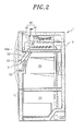
- FIG. 1 is a front view of an exemplary refrigerator according to an embodiment of the present invention and FIG. 2 is a side cross-sectional view of the refrigerator of FIG. 1 .
- a refrigerator 1 having a locking device 100 for an ice bucket 40 may include a main body 10, a storage space 20, an ice space 30, the ice bucket 40, and the locking device 100.
- an embodiment of the present invention includes the components listed above does not mean that the present invention does not include only the above components but means that the present invention can include these components and that the present invention may include other components (for example, technologies widely known with respect to refrigerators). However, the detailed description of known technologies will be omitted if it is deemed that such description would make the description of the present invention unnecessarily vague.
- the main body 10 forms the appearance and supporting structure of the refrigerator 1 and may provide a space in which the components listed above and other components used in the operation of the refrigerator 1 may be formed or installed therein.
- the storage space 20 is formed inside the main body 10 and has a front surface opening.
- the storage space 20 may be partitioned into a refrigerating space and a freezing space by a partition wall.
- the front surface of the storage space 20 may be opened and closed by a pair of doors 21 which rotate and are hinge-coupled with the main body 10.
- the door 21 may be provided with a dispenser 50 which may extract ice generated in the ice space 30 from the outside without opening the door 21.
- the dispenser 50 may include an extraction space 51 which may allow ice to be dispensed, a lever 52 which may select whether to extract ice, and a chute 53 which guides ice discharged through an ice discharge port 40a of the ice bucket 40 to the extraction space 51.
- the ice space 30 may be disposed inside the main body 10 and partitioned from the storage space 20.
- the ice space 30 may be formed to have a front opening.
- the ice space 30 may be disposed at one side of the storage space 20 and may be partitioned from the storage space 20 by a wall of the ice space.
- the ice space 30 may be provided with an ice assembly to generate ice, the ice assembly may be of any well-known design and therefore a detailed description thereof will be omitted.
- the ice bucket 40 may be slidably installed in the ice space 30 to open and close the ice space 30.
- the ice bucket 40 may include an ice storage portion 41 which stores ice generated in the ice space 30 and a cover member 42 which is disposed in front of the ice storage portion 41 to cover the front of the ice space 30.
- the locking device 100 may lock the ice bucket 40 to the ice space 30 to prevent the ice bucket 40 from being drawn out of the ice space 30 by itself.
- the ice bucket 40 may not be drawn out from the ice space 30 by itself as long as a user does not apply an external force and may be kept in a locking state.
- FIG. 3 is a perspective view illustrating an ice bucket that is drawn out from the ice space of the refrigerator illustrated in FIG. 1
- FIG. 4 is an exploded view illustrating the locking device for the ice bucket according to the embodiment of the present invention
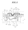
- FIG. 5 is a side cross-sectional view illustrating the locking state of the locking device according to an embodiment of the present invention.
- the locking device 100 may include a projection 110 formed inside the ice space 30, an elasticity module portion 120 formed in the ice bucket 40, and a locking cover 130.
- the projection 110 may protrude from an inner side of the ice space 30 toward the ice bucket 40.
- the projection 110 when the projection 110 is installed on the ceiling 30a of the ice space 30, the projection 110 may be disposed to protrude downward from a position contacting the cover member 42 of the ice bucket 40. Further, when the projection 110 is installed on the floor of the ice space 30, the projection 110 may be disposed to protrude upward from a position contacting the cover member 42 of the ice bucket 40 or the ice storage portion 41.
- the elasticity module portion 120 may be a depression formed in at least one of the upper portion and the lower portion of the ice bucket 40.
- the elasticity providing portion 120 may be integrally formed in the ice bucket 40.
- the elasticity module portion 120 may be provided with the elastic piece 121 which is configured to produce an elastic force.
- One end of the elastic piece 121 is fixed to the ice bucket 40 and the other end is free from (e.g., not connected to) the ice bucket 40 and thus may be formed in the free end state.
- the elastic piece 121 may include a wave portion 121a and a plane portion 121b.
- the wave portion 121a has a structure that increases the elastic force of the elastic piece 121 and the wave portion 121a may be bent in a wave shape with a predetermined length that extends from a point fixed to the ice bucket 40 toward the free end.
- the wave portion 121a has a structure in which protrusions and depressions are repeated, and as a result, its ability to provide elastic force may be increased and is less likely to be deformed or destroyed even though substantial force is applied to the wave portion 121a.
- the plane portion 121b is flatly formed from the wave portion 121a toward the free end and thus may contact the locking cover 130 to provide an elastic force.
- the locking cover 130 is coupled with the elasticity module portion 120 and receives the elastic force from the elastic piece 121 and may cover a portion of the elasticity providing portion 120.
- the locking cover 130 may be formed approximately with a flat side and another side thereof may be disposed with a hook portion 131 protruding to a predetermined height on one side thereof to be locked to the projection 110 by the elastic force from the elastic piece 121.
- the hook portion 131 may include an elastic support portion 131a, a protrusion 131b, and an extending arm 131c.
- the elastic support portion 131a may have a substantially squared shape and may be formed in a structure with a surface integrally coupled with the locking cover 130 and a plurality of surfaces (e.g., the other three surfaces) cut to move independently from the locking cover 130. Therefore, one end of the elastic support portion 131a may be a fixed end which is fixed to the locking cover 130 and the end opposite thereto may be a free end.
- the protrusion 131b may be formed to protrude from the free end of the elastic support portion 131a and to be locked to the projection 110.
- the extending arm 131c extends from the opposing surface of the protrusion 131b of the elastic support portion 131a toward the elastic piece 121 and thus may easily receive the elastic force of the elastic piece 121.
- the elastic force exerted from the elastic piece 121 (for example, the plane portion 121b of the elastic piece 121) is applied to the protrusion 131b through the extending arm 131c and the protrusion 131b is locked into the projection 110 while moving in the same direction as the elastic force.
- the locking cover 130 may be separably coupled with the elasticity module portion 120. Therefore, a portion of the locking cover 130 may also be separated from the elasticity module portion 120 as needed when the locking cover 130 is coupled with the elasticity module portion 120.
- the locking device 100 is installed at one of the upper portion and the lower portion of the ice bucket 40.
- One of the upper portion and the lower portion of the ice bucket 40 may include a first locking hook 11 extending from the ice space 30.
- a second locking hook 12 may extend from the ice bucket 40 to be locked to the first locking hook 11.
- FIG. 6 illustrates that the upper portion of the ice bucket 40 is disposed with the locking device 100 and the lower portion of the ice bucket 40, at which the locking device 100 is not installed, may be disposed with the first locking hook 11 and the second locking hook 12 to lock between the ice space 30 and the ice bucket 40.
- the lower portion of the ice bucket 40 is disposed with the locking device 100 and the upper portion of the ice bucket 40 may be provided with the first locking hook 11 and the second locking hook 12 to lock between the ice space 30 and the ice bucket 40.
- the locking device 100 may also be installed both at the upper portion and the lower portion of the ice bucket 40.
- the elasticity module portion 120 is configured to provide the elastic force and may be formed as a in at least any one of the upper portion and the lower portion of the ice bucket 40 which is disposed in the refrigerator.
- the elasticity module portion 120 may include the elastic piece 121 and the elastic piece 121 may be integrally molded in the ice bucket 40 with one end fixed to the ice bucket 140 and the other end in a free state.
- the elastic piece 121 may be molded to have a wave portion 121a bent in a wave shape, with a predetermined length and extending from a point fixed to the ice bucket 40 toward the free end to produce the elastic force, and the plane portion 121b flatly formed from the wave portion 121a toward the free end.
- the locking cover 130 may be provided separately from the elasticity module portion 120.
- the locking cover 130 may be injection-molded so that the hook portion 131 protrudes on one side thereof.
- the hook portion 131 may have a substantially square shape and may be molded to include the elastic support portion 131a having one surface coupled to the locking cover 130 and three surfaces cut to be separated from the locking cover 130.
- the protrusion 131b protrudes toward the free end of the elastic support portion 131a to be locked to the projection 110 and the extending arm 131c extends from another surface of the protrusion 131b of the elastic support portion 131a toward the elastic piece 121 and is applied with the elastic force.
- the locking cover 130 may be coupled with the elasticity module portion 120 so that a surface of the hook portion 131 contacts the free end of the elastic piece 121.
- the projection 110 is disposed at the inner side of the ice space 30 of the refrigerator so that the hook portion 131 is locked with a portion of the projection 110 protruding toward the ice bucket 40, and as a result the installation of the locking device 100 is complete.
- the user may advantageously draw out the ice bucket with one hand to increase the convenience of the ice bucket and the structure may be simplified to save material cost and improve durability.
- the elastic force may be provided without need of the spring of the metal material and therefore the same elastic force is maintained even after long-term use, thereby increasing the reliability of products.
Landscapes
- Engineering & Computer Science (AREA)
- Mechanical Engineering (AREA)
- Physics & Mathematics (AREA)
- Thermal Sciences (AREA)
- General Engineering & Computer Science (AREA)
- Chemical & Material Sciences (AREA)
- Combustion & Propulsion (AREA)
- Production, Working, Storing, Or Distribution Of Ice (AREA)
- Devices That Are Associated With Refrigeration Equipment (AREA)
Applications Claiming Priority (1)
| Application Number | Priority Date | Filing Date | Title |
|---|---|---|---|
| KR1020150085834A KR101696817B1 (ko) | 2015-06-17 | 2015-06-17 | 아이스버킷 록킹장치를 갖는 냉장고 및 아이스버킷 록킹장치의 설치 방법 |
Publications (2)
| Publication Number | Publication Date |
|---|---|
| EP3150945A1 true EP3150945A1 (fr) | 2017-04-05 |
| EP3150945B1 EP3150945B1 (fr) | 2018-06-06 |
Family
ID=54199101
Family Applications (1)
| Application Number | Title | Priority Date | Filing Date |
|---|---|---|---|
| EP15186856.9A Not-in-force EP3150945B1 (fr) | 2015-06-17 | 2015-09-25 | Réfrigérateur comportant un dispositif de verrouillage pour seau à glace et procédé pour l'installation dudit dispositif |
Country Status (4)
| Country | Link |
|---|---|
| US (1) | US9593877B2 (fr) |
| EP (1) | EP3150945B1 (fr) |
| KR (1) | KR101696817B1 (fr) |
| CN (1) | CN106257206A (fr) |
Families Citing this family (1)
| Publication number | Priority date | Publication date | Assignee | Title |
|---|---|---|---|---|
| US11060782B2 (en) * | 2019-06-26 | 2021-07-13 | Midea Group Co., Ltd. | Refrigerator with ice dispenser closure |
Citations (7)
| Publication number | Priority date | Publication date | Assignee | Title |
|---|---|---|---|---|
| US4245879A (en) * | 1978-06-12 | 1981-01-20 | Magnetic Controls Company | Latch assembly |
| US20060260348A1 (en) * | 2005-05-18 | 2006-11-23 | Maytag Corporation | Refrigerator ice compartment latch |
| EP2172723A2 (fr) * | 2008-10-01 | 2010-04-07 | Samsung Electronics Co., Ltd. | Réfrigérateur et réservoir à glace associé |
| EP2341303A2 (fr) * | 2010-01-04 | 2011-07-06 | Samsung Electronics Co., Ltd. | Appareil de fabrication de glaçons et réfrigérateur doté de celui-ci |
| US20130174599A1 (en) * | 2012-01-06 | 2013-07-11 | Samsung Electronics Co., Ltd. | Refrigerator |
| EP2650625A2 (fr) * | 2012-04-10 | 2013-10-16 | Samsung Electronics Co., Ltd | Réfrigérateur |
| WO2014200318A1 (fr) * | 2013-06-14 | 2014-12-18 | Lg Electronics Inc. | Dispositif de fixation et réfrigérateur le comprenant |
Family Cites Families (13)
| Publication number | Priority date | Publication date | Assignee | Title |
|---|---|---|---|---|
| US3722927A (en) * | 1971-05-20 | 1973-03-27 | Sperry Rand Corp | Latch and return spring |
| US4017937A (en) * | 1975-05-14 | 1977-04-19 | National Union Electric Corporation | Hose coupling for a suction cleaner |
| GB2170547A (en) * | 1985-01-31 | 1986-08-06 | Rexnord Inc | Latch assembly |
| IT240884Y1 (it) * | 1996-09-16 | 2001-04-11 | Candy Spa | Dispositivo di bloccaggio per una porta di un vano di unelettrodomestico,particolarmente per la sportello dello scomparto |
| WO2003018943A1 (fr) * | 2001-08-24 | 2003-03-06 | Arcelik, A.S. | Mecanisme de verrouillage |
| DE102006017804A1 (de) * | 2006-04-18 | 2007-10-25 | BSH Bosch und Siemens Hausgeräte GmbH | Haushaltsgerät |
| KR101351030B1 (ko) * | 2007-06-05 | 2014-01-13 | 엘지전자 주식회사 | 냉장고 |
| KR101129568B1 (ko) * | 2007-07-27 | 2012-03-27 | 박윤식 | 자동폐쇄장치 |
| KR20090131211A (ko) * | 2008-06-17 | 2009-12-28 | 엘지전자 주식회사 | 냉장고의 선반 고정 장치 |
| KR20090094421A (ko) * | 2009-08-14 | 2009-09-07 | 피정배 | 개폐식 방충망의 록 장치 |
| KR20130060864A (ko) * | 2011-11-30 | 2013-06-10 | 엘지전자 주식회사 | 냉장고 |
| CN203605569U (zh) * | 2013-11-01 | 2014-05-21 | 合肥华凌股份有限公司 | 用于冰箱的制冰机及具有其的冰箱 |
| WO2015144238A1 (fr) * | 2014-03-28 | 2015-10-01 | Arcelik Anonim Sirketi | Mécanisme de poignée pour un appareil de réfrigération avec effet d'ouverture naturelle |
-
2015
- 2015-06-17 KR KR1020150085834A patent/KR101696817B1/ko not_active Expired - Fee Related
- 2015-08-24 US US14/834,268 patent/US9593877B2/en not_active Expired - Fee Related
- 2015-09-14 CN CN201510583722.9A patent/CN106257206A/zh active Pending
- 2015-09-25 EP EP15186856.9A patent/EP3150945B1/fr not_active Not-in-force
Patent Citations (7)
| Publication number | Priority date | Publication date | Assignee | Title |
|---|---|---|---|---|
| US4245879A (en) * | 1978-06-12 | 1981-01-20 | Magnetic Controls Company | Latch assembly |
| US20060260348A1 (en) * | 2005-05-18 | 2006-11-23 | Maytag Corporation | Refrigerator ice compartment latch |
| EP2172723A2 (fr) * | 2008-10-01 | 2010-04-07 | Samsung Electronics Co., Ltd. | Réfrigérateur et réservoir à glace associé |
| EP2341303A2 (fr) * | 2010-01-04 | 2011-07-06 | Samsung Electronics Co., Ltd. | Appareil de fabrication de glaçons et réfrigérateur doté de celui-ci |
| US20130174599A1 (en) * | 2012-01-06 | 2013-07-11 | Samsung Electronics Co., Ltd. | Refrigerator |
| EP2650625A2 (fr) * | 2012-04-10 | 2013-10-16 | Samsung Electronics Co., Ltd | Réfrigérateur |
| WO2014200318A1 (fr) * | 2013-06-14 | 2014-12-18 | Lg Electronics Inc. | Dispositif de fixation et réfrigérateur le comprenant |
Also Published As
| Publication number | Publication date |
|---|---|
| EP3150945B1 (fr) | 2018-06-06 |
| KR101696817B1 (ko) | 2017-01-16 |
| CN106257206A (zh) | 2016-12-28 |
| KR20160148968A (ko) | 2016-12-27 |
| US20160370099A1 (en) | 2016-12-22 |
| US9593877B2 (en) | 2017-03-14 |
Similar Documents
| Publication | Publication Date | Title |
|---|---|---|
| US9995527B2 (en) | Refrigerator having locking device for ice bucket and method for installing locking device for ice bucket | |
| US8732910B1 (en) | Appliance handle assembly | |
| KR101618129B1 (ko) | 냉장고 | |
| KR102218309B1 (ko) | 냉장고 | |
| KR101860718B1 (ko) | 이중 도어를 갖는 냉장고 | |
| KR102245371B1 (ko) | 고정 장치 및 이를 포함하는 냉장고 | |
| EP2937651A1 (fr) | Réfrigérateur | |
| EP2937652A1 (fr) | Réfrigérateur | |
| KR20050075781A (ko) | 텔레비전 겸용 냉장고 | |
| CN102341666A (zh) | 冰箱 | |
| US20220290913A1 (en) | Refrigeration appliance with a storage box | |
| CN104956169B (zh) | 具有能调节高度的门搁架的家用制冷器具 | |
| US10041727B2 (en) | Refrigerator having locking device for ice bucket and method for installing locking device for ice bucket | |
| US9593877B2 (en) | Refrigerator having locking device for ice bucket and method for installation of locking device of ice bucket | |
| JP5254067B2 (ja) | 冷蔵庫 | |
| EP3106786A1 (fr) | Système tout-en-un de moteur de vis pour réfrigérateur et procédé de fabrication de celui-ci | |
| US9770795B2 (en) | Refrigerator having locking device for ice bucket and method for installing locking device for ice bucket | |
| CN107289717B (zh) | 冰箱 | |
| CN106196809B (zh) | 冰箱 | |
| CN217154680U (zh) | 家用制冷器具的隔热式箱体及相应的家用制冷器具 | |
| CN209181381U (zh) | 家用制冷器具 | |
| CN110895068A (zh) | 冰箱 | |
| KR101508393B1 (ko) | 냉장고 | |
| KR20150089857A (ko) | 냉장고 |
Legal Events
| Date | Code | Title | Description |
|---|---|---|---|
| PUAI | Public reference made under article 153(3) epc to a published international application that has entered the european phase |
Free format text: ORIGINAL CODE: 0009012 |
|
| AK | Designated contracting states |
Kind code of ref document: A1 Designated state(s): AL AT BE BG CH CY CZ DE DK EE ES FI FR GB GR HR HU IE IS IT LI LT LU LV MC MK MT NL NO PL PT RO RS SE SI SK SM TR |
|
| AX | Request for extension of the european patent |
Extension state: BA ME |
|
| 17P | Request for examination filed |
Effective date: 20170929 |
|
| RBV | Designated contracting states (corrected) |
Designated state(s): AL AT BE BG CH CY CZ DE DK EE ES FI FR GB GR HR HU IE IS IT LI LT LU LV MC MK MT NL NO PL PT RO RS SE SI SK SM TR |
|
| GRAP | Despatch of communication of intention to grant a patent |
Free format text: ORIGINAL CODE: EPIDOSNIGR1 |
|
| RIC1 | Information provided on ipc code assigned before grant |
Ipc: F25C 5/00 20060101AFI20171103BHEP Ipc: F25D 11/02 20060101ALI20171103BHEP Ipc: F25C 5/18 20060101ALI20171103BHEP |
|
| INTG | Intention to grant announced |
Effective date: 20171130 |
|
| GRAS | Grant fee paid |
Free format text: ORIGINAL CODE: EPIDOSNIGR3 |
|
| GRAA | (expected) grant |
Free format text: ORIGINAL CODE: 0009210 |
|
| AK | Designated contracting states |
Kind code of ref document: B1 Designated state(s): AL AT BE BG CH CY CZ DE DK EE ES FI FR GB GR HR HU IE IS IT LI LT LU LV MC MK MT NL NO PL PT RO RS SE SI SK SM TR |
|
| REG | Reference to a national code |
Ref country code: GB Ref legal event code: FG4D |
|
| REG | Reference to a national code |
Ref country code: CH Ref legal event code: EP Ref country code: AT Ref legal event code: REF Ref document number: 1006555 Country of ref document: AT Kind code of ref document: T Effective date: 20180615 |
|
| REG | Reference to a national code |
Ref country code: IE Ref legal event code: FG4D |
|
| REG | Reference to a national code |
Ref country code: DE Ref legal event code: R096 Ref document number: 602015011693 Country of ref document: DE |
|
| REG | Reference to a national code |
Ref country code: FR Ref legal event code: PLFP Year of fee payment: 4 |
|
| REG | Reference to a national code |
Ref country code: NL Ref legal event code: MP Effective date: 20180606 |
|
| REG | Reference to a national code |
Ref country code: LT Ref legal event code: MG4D |
|
| PG25 | Lapsed in a contracting state [announced via postgrant information from national office to epo] |
Ref country code: FI Free format text: LAPSE BECAUSE OF FAILURE TO SUBMIT A TRANSLATION OF THE DESCRIPTION OR TO PAY THE FEE WITHIN THE PRESCRIBED TIME-LIMIT Effective date: 20180606 Ref country code: BG Free format text: LAPSE BECAUSE OF FAILURE TO SUBMIT A TRANSLATION OF THE DESCRIPTION OR TO PAY THE FEE WITHIN THE PRESCRIBED TIME-LIMIT Effective date: 20180906 Ref country code: LT Free format text: LAPSE BECAUSE OF FAILURE TO SUBMIT A TRANSLATION OF THE DESCRIPTION OR TO PAY THE FEE WITHIN THE PRESCRIBED TIME-LIMIT Effective date: 20180606 Ref country code: CY Free format text: LAPSE BECAUSE OF FAILURE TO SUBMIT A TRANSLATION OF THE DESCRIPTION OR TO PAY THE FEE WITHIN THE PRESCRIBED TIME-LIMIT Effective date: 20180606 Ref country code: NO Free format text: LAPSE BECAUSE OF FAILURE TO SUBMIT A TRANSLATION OF THE DESCRIPTION OR TO PAY THE FEE WITHIN THE PRESCRIBED TIME-LIMIT Effective date: 20180906 Ref country code: SE Free format text: LAPSE BECAUSE OF FAILURE TO SUBMIT A TRANSLATION OF THE DESCRIPTION OR TO PAY THE FEE WITHIN THE PRESCRIBED TIME-LIMIT Effective date: 20180606 Ref country code: ES Free format text: LAPSE BECAUSE OF FAILURE TO SUBMIT A TRANSLATION OF THE DESCRIPTION OR TO PAY THE FEE WITHIN THE PRESCRIBED TIME-LIMIT Effective date: 20180606 |
|
| PGFP | Annual fee paid to national office [announced via postgrant information from national office to epo] |
Ref country code: FR Payment date: 20180927 Year of fee payment: 4 |
|
| PG25 | Lapsed in a contracting state [announced via postgrant information from national office to epo] |
Ref country code: GR Free format text: LAPSE BECAUSE OF FAILURE TO SUBMIT A TRANSLATION OF THE DESCRIPTION OR TO PAY THE FEE WITHIN THE PRESCRIBED TIME-LIMIT Effective date: 20180907 Ref country code: LV Free format text: LAPSE BECAUSE OF FAILURE TO SUBMIT A TRANSLATION OF THE DESCRIPTION OR TO PAY THE FEE WITHIN THE PRESCRIBED TIME-LIMIT Effective date: 20180606 Ref country code: HR Free format text: LAPSE BECAUSE OF FAILURE TO SUBMIT A TRANSLATION OF THE DESCRIPTION OR TO PAY THE FEE WITHIN THE PRESCRIBED TIME-LIMIT Effective date: 20180606 Ref country code: RS Free format text: LAPSE BECAUSE OF FAILURE TO SUBMIT A TRANSLATION OF THE DESCRIPTION OR TO PAY THE FEE WITHIN THE PRESCRIBED TIME-LIMIT Effective date: 20180606 |
|
| REG | Reference to a national code |
Ref country code: AT Ref legal event code: MK05 Ref document number: 1006555 Country of ref document: AT Kind code of ref document: T Effective date: 20180606 |
|
| PG25 | Lapsed in a contracting state [announced via postgrant information from national office to epo] |
Ref country code: NL Free format text: LAPSE BECAUSE OF FAILURE TO SUBMIT A TRANSLATION OF THE DESCRIPTION OR TO PAY THE FEE WITHIN THE PRESCRIBED TIME-LIMIT Effective date: 20180606 |
|
| PG25 | Lapsed in a contracting state [announced via postgrant information from national office to epo] |
Ref country code: RO Free format text: LAPSE BECAUSE OF FAILURE TO SUBMIT A TRANSLATION OF THE DESCRIPTION OR TO PAY THE FEE WITHIN THE PRESCRIBED TIME-LIMIT Effective date: 20180606 Ref country code: SK Free format text: LAPSE BECAUSE OF FAILURE TO SUBMIT A TRANSLATION OF THE DESCRIPTION OR TO PAY THE FEE WITHIN THE PRESCRIBED TIME-LIMIT Effective date: 20180606 Ref country code: CZ Free format text: LAPSE BECAUSE OF FAILURE TO SUBMIT A TRANSLATION OF THE DESCRIPTION OR TO PAY THE FEE WITHIN THE PRESCRIBED TIME-LIMIT Effective date: 20180606 Ref country code: PL Free format text: LAPSE BECAUSE OF FAILURE TO SUBMIT A TRANSLATION OF THE DESCRIPTION OR TO PAY THE FEE WITHIN THE PRESCRIBED TIME-LIMIT Effective date: 20180606 Ref country code: AT Free format text: LAPSE BECAUSE OF FAILURE TO SUBMIT A TRANSLATION OF THE DESCRIPTION OR TO PAY THE FEE WITHIN THE PRESCRIBED TIME-LIMIT Effective date: 20180606 Ref country code: EE Free format text: LAPSE BECAUSE OF FAILURE TO SUBMIT A TRANSLATION OF THE DESCRIPTION OR TO PAY THE FEE WITHIN THE PRESCRIBED TIME-LIMIT Effective date: 20180606 Ref country code: IS Free format text: LAPSE BECAUSE OF FAILURE TO SUBMIT A TRANSLATION OF THE DESCRIPTION OR TO PAY THE FEE WITHIN THE PRESCRIBED TIME-LIMIT Effective date: 20181006 |
|
| PGFP | Annual fee paid to national office [announced via postgrant information from national office to epo] |
Ref country code: DE Payment date: 20181127 Year of fee payment: 4 |
|
| PG25 | Lapsed in a contracting state [announced via postgrant information from national office to epo] |
Ref country code: IT Free format text: LAPSE BECAUSE OF FAILURE TO SUBMIT A TRANSLATION OF THE DESCRIPTION OR TO PAY THE FEE WITHIN THE PRESCRIBED TIME-LIMIT Effective date: 20180606 Ref country code: SM Free format text: LAPSE BECAUSE OF FAILURE TO SUBMIT A TRANSLATION OF THE DESCRIPTION OR TO PAY THE FEE WITHIN THE PRESCRIBED TIME-LIMIT Effective date: 20180606 |
|
| REG | Reference to a national code |
Ref country code: DE Ref legal event code: R097 Ref document number: 602015011693 Country of ref document: DE |
|
| PLBE | No opposition filed within time limit |
Free format text: ORIGINAL CODE: 0009261 |
|
| STAA | Information on the status of an ep patent application or granted ep patent |
Free format text: STATUS: NO OPPOSITION FILED WITHIN TIME LIMIT |
|
| PG25 | Lapsed in a contracting state [announced via postgrant information from national office to epo] |
Ref country code: MC Free format text: LAPSE BECAUSE OF FAILURE TO SUBMIT A TRANSLATION OF THE DESCRIPTION OR TO PAY THE FEE WITHIN THE PRESCRIBED TIME-LIMIT Effective date: 20180606 |
|
| REG | Reference to a national code |
Ref country code: CH Ref legal event code: PL |
|
| 26N | No opposition filed |
Effective date: 20190307 |
|
| PG25 | Lapsed in a contracting state [announced via postgrant information from national office to epo] |
Ref country code: DK Free format text: LAPSE BECAUSE OF FAILURE TO SUBMIT A TRANSLATION OF THE DESCRIPTION OR TO PAY THE FEE WITHIN THE PRESCRIBED TIME-LIMIT Effective date: 20180606 Ref country code: SI Free format text: LAPSE BECAUSE OF FAILURE TO SUBMIT A TRANSLATION OF THE DESCRIPTION OR TO PAY THE FEE WITHIN THE PRESCRIBED TIME-LIMIT Effective date: 20180606 |
|
| REG | Reference to a national code |
Ref country code: BE Ref legal event code: MM Effective date: 20180930 |
|
| REG | Reference to a national code |
Ref country code: IE Ref legal event code: MM4A |
|
| PG25 | Lapsed in a contracting state [announced via postgrant information from national office to epo] |
Ref country code: LU Free format text: LAPSE BECAUSE OF NON-PAYMENT OF DUE FEES Effective date: 20180925 |
|
| PG25 | Lapsed in a contracting state [announced via postgrant information from national office to epo] |
Ref country code: IE Free format text: LAPSE BECAUSE OF NON-PAYMENT OF DUE FEES Effective date: 20180925 |
|
| PG25 | Lapsed in a contracting state [announced via postgrant information from national office to epo] |
Ref country code: BE Free format text: LAPSE BECAUSE OF NON-PAYMENT OF DUE FEES Effective date: 20180930 Ref country code: CH Free format text: LAPSE BECAUSE OF NON-PAYMENT OF DUE FEES Effective date: 20180930 Ref country code: LI Free format text: LAPSE BECAUSE OF NON-PAYMENT OF DUE FEES Effective date: 20180930 |
|
| PG25 | Lapsed in a contracting state [announced via postgrant information from national office to epo] |
Ref country code: AL Free format text: LAPSE BECAUSE OF FAILURE TO SUBMIT A TRANSLATION OF THE DESCRIPTION OR TO PAY THE FEE WITHIN THE PRESCRIBED TIME-LIMIT Effective date: 20180606 |
|
| PG25 | Lapsed in a contracting state [announced via postgrant information from national office to epo] |
Ref country code: MT Free format text: LAPSE BECAUSE OF NON-PAYMENT OF DUE FEES Effective date: 20180925 |
|
| PG25 | Lapsed in a contracting state [announced via postgrant information from national office to epo] |
Ref country code: TR Free format text: LAPSE BECAUSE OF FAILURE TO SUBMIT A TRANSLATION OF THE DESCRIPTION OR TO PAY THE FEE WITHIN THE PRESCRIBED TIME-LIMIT Effective date: 20180606 |
|
| REG | Reference to a national code |
Ref country code: DE Ref legal event code: R119 Ref document number: 602015011693 Country of ref document: DE |
|
| PG25 | Lapsed in a contracting state [announced via postgrant information from national office to epo] |
Ref country code: PT Free format text: LAPSE BECAUSE OF FAILURE TO SUBMIT A TRANSLATION OF THE DESCRIPTION OR TO PAY THE FEE WITHIN THE PRESCRIBED TIME-LIMIT Effective date: 20180606 |
|
| PG25 | Lapsed in a contracting state [announced via postgrant information from national office to epo] |
Ref country code: HU Free format text: LAPSE BECAUSE OF FAILURE TO SUBMIT A TRANSLATION OF THE DESCRIPTION OR TO PAY THE FEE WITHIN THE PRESCRIBED TIME-LIMIT; INVALID AB INITIO Effective date: 20150925 Ref country code: MK Free format text: LAPSE BECAUSE OF NON-PAYMENT OF DUE FEES Effective date: 20180606 |
|
| PG25 | Lapsed in a contracting state [announced via postgrant information from national office to epo] |
Ref country code: DE Free format text: LAPSE BECAUSE OF NON-PAYMENT OF DUE FEES Effective date: 20200401 |
|
| GBPC | Gb: european patent ceased through non-payment of renewal fee |
Effective date: 20190925 |
|
| PG25 | Lapsed in a contracting state [announced via postgrant information from national office to epo] |
Ref country code: FR Free format text: LAPSE BECAUSE OF NON-PAYMENT OF DUE FEES Effective date: 20190930 Ref country code: GB Free format text: LAPSE BECAUSE OF NON-PAYMENT OF DUE FEES Effective date: 20190925 |