EP3151164A2 - Procédé de détection de débris d'objets étrangers - Google Patents
Procédé de détection de débris d'objets étrangers Download PDFInfo
- Publication number
- EP3151164A2 EP3151164A2 EP16206900.9A EP16206900A EP3151164A2 EP 3151164 A2 EP3151164 A2 EP 3151164A2 EP 16206900 A EP16206900 A EP 16206900A EP 3151164 A2 EP3151164 A2 EP 3151164A2
- Authority
- EP
- European Patent Office
- Prior art keywords
- image
- fod
- background
- analysis module
- images
- Prior art date
- Legal status (The legal status is an assumption and is not a legal conclusion. Google has not performed a legal analysis and makes no representation as to the accuracy of the status listed.)
- Withdrawn
Links
Images


Classifications
-
- G—PHYSICS
- G06—COMPUTING OR CALCULATING; COUNTING
- G06T—IMAGE DATA PROCESSING OR GENERATION, IN GENERAL
- G06T7/00—Image analysis
- G06T7/30—Determination of transform parameters for the alignment of images, i.e. image registration
- G06T7/33—Determination of transform parameters for the alignment of images, i.e. image registration using feature-based methods
-
- G—PHYSICS
- G06—COMPUTING OR CALCULATING; COUNTING
- G06F—ELECTRIC DIGITAL DATA PROCESSING
- G06F18/00—Pattern recognition
- G06F18/20—Analysing
- G06F18/22—Matching criteria, e.g. proximity measures
-
- G—PHYSICS
- G06—COMPUTING OR CALCULATING; COUNTING
- G06V—IMAGE OR VIDEO RECOGNITION OR UNDERSTANDING
- G06V10/00—Arrangements for image or video recognition or understanding
- G06V10/40—Extraction of image or video features
- G06V10/44—Local feature extraction by analysis of parts of the pattern, e.g. by detecting edges, contours, loops, corners, strokes or intersections; Connectivity analysis, e.g. of connected components
- G06V10/443—Local feature extraction by analysis of parts of the pattern, e.g. by detecting edges, contours, loops, corners, strokes or intersections; Connectivity analysis, e.g. of connected components by matching or filtering
- G06V10/449—Biologically inspired filters, e.g. difference of Gaussians [DoG] or Gabor filters
- G06V10/451—Biologically inspired filters, e.g. difference of Gaussians [DoG] or Gabor filters with interaction between the filter responses, e.g. cortical complex cells
-
- G—PHYSICS
- G06—COMPUTING OR CALCULATING; COUNTING
- G06V—IMAGE OR VIDEO RECOGNITION OR UNDERSTANDING
- G06V10/00—Arrangements for image or video recognition or understanding
- G06V10/70—Arrangements for image or video recognition or understanding using pattern recognition or machine learning
- G06V10/74—Image or video pattern matching; Proximity measures in feature spaces
- G06V10/761—Proximity, similarity or dissimilarity measures
-
- G—PHYSICS
- G06—COMPUTING OR CALCULATING; COUNTING
- G06V—IMAGE OR VIDEO RECOGNITION OR UNDERSTANDING
- G06V10/00—Arrangements for image or video recognition or understanding
- G06V10/70—Arrangements for image or video recognition or understanding using pattern recognition or machine learning
- G06V10/82—Arrangements for image or video recognition or understanding using pattern recognition or machine learning using neural networks
-
- G—PHYSICS
- G06—COMPUTING OR CALCULATING; COUNTING
- G06V—IMAGE OR VIDEO RECOGNITION OR UNDERSTANDING
- G06V20/00—Scenes; Scene-specific elements
- G06V20/50—Context or environment of the image
- G06V20/52—Surveillance or monitoring of activities, e.g. for recognising suspicious objects
-
- G—PHYSICS
- G06—COMPUTING OR CALCULATING; COUNTING
- G06V—IMAGE OR VIDEO RECOGNITION OR UNDERSTANDING
- G06V20/00—Scenes; Scene-specific elements
- G06V20/50—Context or environment of the image
- G06V20/56—Context or environment of the image exterior to a vehicle by using sensors mounted on the vehicle
- G06V20/58—Recognition of moving objects or obstacles, e.g. vehicles or pedestrians; Recognition of traffic objects, e.g. traffic signs, traffic lights or roads
-
- G—PHYSICS
- G06—COMPUTING OR CALCULATING; COUNTING
- G06V—IMAGE OR VIDEO RECOGNITION OR UNDERSTANDING
- G06V20/00—Scenes; Scene-specific elements
- G06V20/50—Context or environment of the image
- G06V20/56—Context or environment of the image exterior to a vehicle by using sensors mounted on the vehicle
- G06V20/588—Recognition of the road, e.g. of lane markings; Recognition of the vehicle driving pattern in relation to the road
-
- G—PHYSICS
- G08—SIGNALLING
- G08G—TRAFFIC CONTROL SYSTEMS
- G08G5/00—Traffic control systems for aircraft
- G08G5/20—Arrangements for acquiring, generating, sharing or displaying traffic information
- G08G5/22—Arrangements for acquiring, generating, sharing or displaying traffic information located on the ground
-
- G—PHYSICS
- G06—COMPUTING OR CALCULATING; COUNTING
- G06T—IMAGE DATA PROCESSING OR GENERATION, IN GENERAL
- G06T2207/00—Indexing scheme for image analysis or image enhancement
- G06T2207/20—Special algorithmic details
- G06T2207/20084—Artificial neural networks [ANN]
-
- G—PHYSICS
- G06—COMPUTING OR CALCULATING; COUNTING
- G06T—IMAGE DATA PROCESSING OR GENERATION, IN GENERAL
- G06T2207/00—Indexing scheme for image analysis or image enhancement
- G06T2207/30—Subject of image; Context of image processing
- G06T2207/30232—Surveillance
Definitions
- This invention discloses a remote measurement system for monitoring the surface areas including but not limited to airport runways, taxiways, aprons and adjacent areas to detect the generation of a FOD in real time and with maximum accuracy.
- FOD Foreign Object Debris
- a substance, debris or article alien to a vehicle or system which could potentially cause damage, particularly in aerospace setting.
- FOD could be caused on the runways, taxiways, aprons and adjacent areas by different sources like a particle coming from a construction, ground vehicle, aircraft or an animal.
- the diversity in the cause of the aforementioned foreign debris makes it hard to constrain to a specific shape, color or a material property.
- the ability to automatically distinguish a foreign object on the mission critical surfaces on the airports has a vital importance for safe operation of the ground vehicles and aircrafts.
- the foreign object debris could often be small and even harmless.
- this task is performed manually during regular on-site inspections where single, or a team of experts make routine patrols on the airport surface and perform visual inspection to enable a clean and safe operation.
- such a manual process is not always reliable and prone to human error that cannot be tolerated.
- such techniques endanger the continuity of the airport operations and cost a lot of time and increases the risk of accidents especially on the busy airports.
- US patent document n. US 20130329052 A1 discloses a surveillance system for detecting a foreign object, debris, or weapon impact damage in an airfield.
- the systems comprises static or moving cameras that are mounted over an aircraft flying over the airfield to capture images and one or more infrared illuminators for providing artificial illumination under low visibility or low ambient illumination conditions. It is also disclosed the estimation of weapon repair using the camera images and also sound caused by the weapon impact.
- Sobel and Scharr filters are used for detecting edge images and using global histogram and statistical analysis to compare each image for detecting landing or take of aircrafts and ground vehicles. The Sobel and Scharr filters however are rather limited in terms of obtaining image edge characteristics.
- US8022841B2 proposes a system using a radar based technique to detect and remove FODs on the airport surface. More in detail the system uses tower-mounted millimeter wave sensor (MWS) detector. Using radar technology has the risk of interfering with the existing airport and aircraft equipment.
- MRS millimeter wave sensor
- a 3D profile of the surface is estimated using a 3D laser sensor carried by a land vehicle travelling on the desired detection area.
- a camera is located next to the scanner to visually inspect the detected FOD for providing richer detection information.
- This technique measures the surface abnormality with the scanner and uses the camera to provide detection information about the FOD.
- the main drawback of this technique resides on the fact that the inspection on the desired detection area cannot be performed constantly, since the plane traffic on the desired area has to be stopped in order to allow the passage of the vehicle carrying the 3D laser sensor.
- US20160061746A1 discloses a method for detecting foreign objects in or on a subject of interest using a predefined plurality of colors from a color palette.
- the method comprises a calibration step using an imaging system to first analyze the assembly where there is no foreign object. After the calibration step the system tries to observe changes in the assembly line that is not in accordance with the defined set of negative image examples.
- the color selection component is configured to classify colors from a defined color palette according to a color content of the first set of images into at least first and second classes.
- this system requires a calibration of the assembly line color pallette for a series of images where there is no foreign object is present. Only after that, the system could identify the existence of the foreign objects.
- the system comprises a plurality of wide spectrum passive sensors and required optical components and housing to capture the RGB (red-green-blue) or monochrome signal from the region of interest that the sensor is directed at.
- the signal captured on the sensor is further used for analysis using image processing components detailed in the disclosure.
- the present invention also relates to the fields of deep learning and convolutional filters where the optimal filters to detect surface characteristics are actually learned from scene in contrast to other inventions where predefined filters are used. This provides great advantage for a robust image understanding and high accuracy operation.
- the system is further capable of analyzing the scene and creating an alarm with different emergency levels depending on the type size and structure of the detected foreign object.
- the present invention proposes more robust and accurate filters obtained using convolutional deep neural networks to solve the foreign object debris problem and overcome the challenges encountered in the pipeline.
- the main advantage of this technique is that the convolutional network filters actually learn the surface characteristics for obtaining an efficient and robust edge and line identification specific to the airport surface.
- the lack of accuracy in prior art for said foreign object detection under varying lighting conditions is resolved with the disclosed convolutional neural networks that can learn and adapt the data analysis pipeline depending on the scene characteristics under varying illumination conditions.
- the multi-layer perceptron based back propagation network is utilized with various convolutional filters that learn to adapt their weights for the data presented to the deep network as ground truth information.
- the present invention also provides a detailed technique to align succeeding images on the background image to perform FOD detection.
- Convolutional neural network based feature point matching is used to estimate homography matrix coefficients for proper image alignment that is not addressed in the prior art.
- the plurality of the image sensors and the optical equipment that are located in a direct line of sight to the runway could be controlled remotely from a main location and has the capability to move and monitor a specific area of interest.
- the selection of the area is automatically performed by the processing unit depending on the environmental conditions.
- the location of the detected foreign object could be reported using the viewing direction of the optical equipment and the lasers pointing to the detected FOD. Visual inspection on the user interface of the processing system and mobile device monitoring interface could also be possible.
- the present invention relates to a computer implemented method for monitoring a selected surface area (an airport runway, taxiway, apron or adjacent areas...) and detecting foreign object debris within a detection system
- a computer implemented method for monitoring a selected surface area comprising; at least one image sensor directed to at least a portion of the selected surface area, a user terminal, a database and a main processing unit comprising a global image analysis module, a local image analysis module, an image registration module, a background analysis module and a FOD Analysis module, scene change detection module, logistic regression module, homography estimation module, time module, frequency module, a decision module.
- the image sensors can be CCD (Charge Coupled Device) and/or CMOS (Complementary Metal Oxide Semiconductor) sensors recording the visible and infrared signals coming from the surface. Also, optical equipments are attached to the sensors for focusing the scene on the image sensor. The frames captured by the image sensors are processed within the main processing unit.
- the main processing unit operating on monochrome or color video signal and analyzing the area of interest can be selected from a group comprising a microprocessor, microcontroller, FPGA, ASIC etc. and can be located in a personal computer, a laptop, a tablet PC etc.
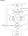
- the illustrative flowchart in Figure 1 describes the high level pipeline of the system.
- the system is initialized (101) and starts with a hardware and software initialization of the systems (102). If for any reason that either software or hardware initialization fails, system goes back to the start stage and restarts the system until maximum number of unsuccessful trials are reached or the system starts successfully.
- the camera positions are set to their predefined initial state (103).
- frame capture starts (104).
- the captured frames (a first frame called previous frame and a second frame called current frame) are sent to the main processing unit for analysis (105).
- the decision module at the processing unit outputs the result of the analysis to the user terminal (such as a computer, tablet PC or smart phone etc. having a user interface such as a screen/touch screen and keyboard/touchpad etc.) and reports in a database (such as a remote database accessible through internet or memory of the user interface) (106).
- the user terminal such as a computer, tablet PC or smart phone etc. having a user interface such as a screen/touch screen and
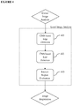
- the flowchart in Figure 2 illustrates the details of the image analysis module where the captured image (201) in a visible or infrared part of the spectrum via at least one image sensor is fed to the Global Image Analysis module for detecting sudden scene changes potentially due to a reflection on the camera, sudden cloud/sun changes, obstruction in the camera view, ground vehicle or aircraft entering to the scene (202). Such cases cause a failure, and return the system back to the new image capture state.
- the Local Image Analysis module is initiated (203).
- the Local Image Analysis module the local characteristics of the scene are analyzed. The analysis is performed by extracting the edges and lines in the scene using a convolutional deep neural network. These local structures are later used to locate the runway area and define the interest region.
- the Image Registration module takes care of the alignment of the current frame with respect to the previous frames and the background image (that can be a first image taken by the image sensors or an image stored in the database) (204).
- This alignment procedure is important for estimating the geometric distortion of the scene after consecutive shots and hence obtaining the accurate location of the scene with respect to the whole viewpoint. This will also be important for reporting purposes when a foreign object is found in the scene. For some reasons (inaccuracy in the motor control units, or strong winds that affect the camera position), it is possible that an accurate registration of the scene is not possible. This is an unwanted situation but the system has to recover from such cases and a failure case returns the system back to the new frame capture module.
- a successful registration leads to the following step where the Background Analysis module analyses the registered and the previously received images and updates the background information using an adaptive infinite impulse response (IIR) filter with coefficients ⁇ and (1- ⁇ ) where ⁇ corresponds to the weight of the registered image (205).
- IIR adaptive infinite impulse response
- the registered image is used to update the active background with where the update coefficients are defined depending on the weather conditions and changes in the lightness.
- the forgetting coefficient ( ⁇ ) is increased if there is strong change in the light (sunset, sunrise), in order to incorporate high reaction response to environmental changes.
- the FOD Analysis module (206) is triggered and the changes in the local characteristics (edges, corners and the aforementioned keypoint descriptors) of the scene is analyzed in order to detect a foreign object in the analyzed surface.
- the final output is delivered to the user terminal and the database is updated with the obtained output.
- FIG. 3 further details the Global Image Analysis module (202) into sub components.
- Global image analysis module aims to detect sudden scene changes potentially due to a reflection on the camera, sudden cloud/sun changes, obstruction in the camera view due to potential unpredictable reasons, ground vehicle or aircraft entering to the scene.
- the proposed method involves an analysis of cumulative distribution function (CDF) of pixel values in the latest captured image (301).
- CDF cumulative distribution function
- PDF probability distribution function
- PDF is obtained for the current image (the last received image).
- PDF is obtained by calculating the probability of each pixel intensity between 0-255 throughout the image.
- CDF is later obtained by cumulative summation of PDF from 0 to 255. This step accounts for the linearization of the CDF of the pixel value distribution in the image.
- the time domain analysis (302) involves obtaining a cosine similarity metric using the probability distribution of the pixel values between the current and the background image.
- a frequency domain analysis is performed (303).
- amplitude and phase components of a Fourier Transformation of the pixel probability distribution are analyzed. More specifically, an NxN Fast Fourier Transform (FFT) is applied on the current and the background image where N is a design parameter to be determined depending on the image resolution.
- FFT Fast Fourier Transform
- the cosine similarity results from the time and frequency modules are later merged at the scene change detection module (304).
- the logistic regression module If the output of the logistic regression module is below 0.5 (no scene change), the following local image analysis module is triggered. If the sigmoid output is above 0.5 (scene change is detected), the system goes back to the new image capture stage (201).
- Figure 4 describes the details of the Local Image Analysis module where convolutional neural networks are used to obtain the surface local characteristics for further processing.
- Deep neural networks have been widely applied in many computer vision areas and have obtained superior performance compared to the conventional techniques. Therefore, we propose such a method for extracting local edge (401) and line (402) structure of the scene.
- the extracted edge and line characteristics are also used to estimate the region of interest (403) to find the boundaries of the runway. Only the region inside the runway boundary is used during the image registration step. This enables to remove unwanted areas from being considered in homography mapping as will be described later.
- the following registration module is initiated.
- Figure 5 describes the Image Registration step where the consecutive frames of the same scene are pixel wise mapped to the background. This step is vital in order to obtain an accurate FOD localization. Since the changes in the succeeding local frame regions are potential FOD candidates, a proper mapping provides accurate region analysis.
- the registration starts with identification of the image local points, a.k.a. keypoints (501).
- the keypoints are the important reference locations in the image that will be matched in the succeeding frame for an accurate mapping.
- a novel convolutional neural network based technique is used for the task of detecting the stable image locations.
- the convolutional neural network filters are applied to each frame in order to obtain the stable keypoints on the image.
- the high level network activations of the convolutional network are used as the robust descriptors of the individual keypoints (502).
- the matching is performed by extracting the 512 dimensional fully connected layer outputs from the network (806). These outputs are trained with ground truth keypoint data where a positive class represents matching keypoints and negative class represents negative keypoints.
- a triplet loss function is minimized where a keypoint descriptor is forced to be as close as possible to its matches and as far as possible from the non-matching descriptors.
- the closeness is defined as using a Euclidean distance between the 512 dimensional embedding vectors e; e i ⁇ e j 2 + ⁇ ⁇ e i ⁇ e k 2 where i and j correspond to matching descriptors and i and k are non-matching descriptors.
- ⁇ is the margin enforced between matching and non-matching descriptors.
- a homography estimation module (503) is performed to find coefficients of a homography matrix matching two frames (the current and the background). The homography estimation module runs multiple times. At each iteration, a random set of the matched points are used to estimate six parametric affine model to eliminate potential outliers in the selected keypoints. The estimated homograpy matrix is used to align the current image on the background image.
- the quality of the alignment is evaluated using a pixel wise similarity metric using sum of squared differences (SSD) between the background and aligned (registered) current image (504).
- SSD sum of squared differences
- This evaluation provides the quality of matching by comparing the results of the similarity metric with a threshold and the decision to return back to image capture or go forward with the background analysis is taken depending on the result whether it is below or above the threshold.
- the threshold for successful registration is learned from set of training images where ground truth keypoint matches are used for homography estimation. Estimated homography matrix is used to align the images in order to obtain a similarity metric distribution for correctly aligned images.
- FIG 6 shows the details of the Background Analysis module where initially a background stability check is performed (601).
- This stability check aims to verify the accuracy of the registration of the current image with the previously accumulated background image. This is done by aligning the edge image of the current image found in local image analysis module (401) to the background edge image. The dominant edges of the two frames are matched in order to verify a stable registration. The precision (Pr) and recall (Rc) values of the aligned edge pixels on the two images are evaluated on the binary edge map. If the stability is not satisfied ( ⁇ 90% both on precision and recall), system goes back to new image capture. If a successful background registration is observed ( ⁇ 90% on precision and recall), the active background image is updated (602).
- the update is performed using an infinite impulse filter with adaptive coefficients ⁇ and (1- ⁇ ).
- the aim of using F1 score for the update coefficients is to bias the correctly registered images to update the background strongly.
- Background update is performed using the estimated coefficients where each pixel is updated using partially the current ( ⁇ ) and partially the background pixel values (1- ⁇ ). Following the update of the backgrounds FOD analysis is performed.
- Figure 7 shows the detailed description of the FOD Analysis module.
- the background is updated in the previous step and is removed from the current image to obtain a clean foreground image (701).
- the obtained foreground image is further processed using morphological operations (First erosion and later dilation) to remove the potential noise and small registration inconsistencies in the current image (702).
- the stable foreground regions are located using connected component analysis (703).
- the size, shape and temporal duration of the connected components are analyzed to be assigned to the FOD candidate regions (704).
- the analysis is performed by comparing the total size of the region with a predefined pixel size, The temporal duration is also similarly predefined for being accepted as a FOD candidate.
- the shape analysis is done by measuring the height-width ratio of the smallest rectangle covering the connected component and comparing it with a predefined value. All the predefined values for connected component regions are manually defined using visual inspections in order to minimize false positives and maximize true positives.
- the candidate regions are processed by the convolutional deep neural network that is trained offline using the ground truth FOD images (705).
- the training and network architecture of the convolutional deep neural network is explained future in the document.
- the deep neural network processes the candidate regions and outputs a probability value between 0 and 1 where the higher value indicates higher likelihood that the candidate region defines a FOD.
- the network output is used to decide if the candidate region contains a FOD.
- the decision is sent through the client interface with the predefined risk levels (defined by the network output value) to be further analyzed by the operator, and a new image capture signal is triggered.
- the risk levels are defined during the network training where low, medium and high risk FODs are presented to the operator for action.
- Figure 8 illustrates how the operator can further decide to remove the FOD or snooze until a given time, or totally ignore if the risk is not critical (801). If the operator decides to initiate the FOD removal, a laser pointer system comprising a laser pointer and a movement mechanism can show the location of the FOD on the ground surface by radiating light thereon (802).
- the pixel location of the detected FOD is used to calculate the position of the FOD on the ground using the calibrated camera and the predefined GPS coordinates of the region.
- the calculated yaw and pitch angle is sent to a movement mechanism coupled to the laser pointer.
- Direction of the laser pointer is controlled by the movement mechanism according to the signal coming from the localization module.
- the ground control units are also informed and the GPS coordinates of the detected FOD is sent to the mobile device (803).
- the issue is resolved and updated accordingly in the database (804).
- Figure 9 shows the general convolutional deep neural network architecture. This figure is mostly for illustration purposes; this invention presents the general guidelines for creating a deep convolutional neural network architecture and how to train it for FOD detection purposes.
- the proposed deep network consists of multiple convolutional layers and max pooling layers in between.
- four convolutional layers are shown and each one is followed by a max pooling layer except for the last one. Output of the last convolutional layer is connected to a fully connected layer.
- the network is trained using supervised learning techniques where a ground truth data input is used to teach the network to optimize for the given input structures.
- predefined edge and line images are shown to the system and the weights are adapted using backpropagation of the error through the network.
- the input image patch of size NxM (901) is cropped from the full resolution image for the analysis.
- 64x64 is selected in the figure for illustration purposes, since it is very common to use 64x64 patches in the literature for both computational (good fit for processors) and practical (good size for image understanding) reasons.
- the convolutional filters as shown in (902) are the actual weights that are learned during the training using the ground truth annotated data. Convolving the image patch with M different filters produce the M channel output (feature maps) (903). The convolution of each filter on the image patch produces the individual pixel intensities of the feature maps (904).
- the max pooling operation following the convolution operation does not change the number of feature maps (channels) but decreases the resolution of the feature maps by two since a stride of two is used in the network. No zero padding is applied on the input image hence decrease in resolution is not an exact multiplier of 2, (64x64 -> 30x30). Similar convolution and max pooling operations increase the channels and decrease the feature map resolution (905). Last convolution layer is not followed by a max pooling layer but connected to the final fully connected layers (906).
- the fully connected layers produce the final output of three dimensions for the three classification task of "edge detection”, "line detection” and "none” (907).
- This network is a multi-class perceptron network with multiple annotations in the ground truth data.
- Each patch annotated as line also belongs to an edge point and hence the two output activations are fired simultaneously for an image patch containing a line.
- the backpropagation in the training phase is also done accordingly using the cross entropy loss. However, if the image patch is only an edge but not a line, only the edge output is activated.
- the commonly used softmax layer in the final output is not used. Instead, the raw outputs of the leaky rectified linear units of the last fully connected perceptron layer are used with a threshold learned from the dataset .
- the network is initially trained using over 100K ground truth edge and line image patches. Data augmentation is done by mirroring, additive gaussian noise, cropping, scaling and contrast changes. Such images are obtained from the airport runway under different lighting and weather conditions (sun, rain or snow), and is updated for different surface textures in different airports.
- the weights are not trained from scratch but fine-tuned for different surface characteristics where the learning rate of the final layers are kept constant while the rest are set to very small or even zero.
- the global learning rate is also decayed after each epoch to account in accordance with general guidelines.
- the proposed deep network classifies the image patches as "edge", "line” or “none”. This classification results are used in local image analysis and image registration modules in the algorithmic pipeline. It is relatively easy to collect over 100K training material with ground truth edge and line locations. However, for the Keypoint detection and FOD detection tasks it is hard to obtain high number of ground truth material, Therefore, the same network is reused during the keypoint and FOD detection modules without from-scratch training. The way to use the same network in a different classification task without retraining lies in the transfer learning methods.
- Transfer learning aims at storing the knowledge gained while solving one problem and applying it to a different but a related problem.
- the way transfer learning applied in the proposed invention is as follows.
- the deep network trained to learn the low level structure of the edges and lines are accounted as valuable information for detecting the FOD regions.
- FOD regions constitute similar surface structure and hence a network trained to edges and lines that already learned the low level structures of the surface and could well be adapted to the new task of FOD detection.
- the way to do this is to remove the final classification layer from the network and use the last fully connected layer activations as a feature descriptor.
- the obtained feature descriptors are then used with a smaller number of training samples ( ⁇ 5K) to train a shallow (single layer) neural network or a Support Vector Machine (SVM) classifier to make the final classification for the FOD and keypoint detection tasks (501, 705).
- This trick is rather common in the cases where only a limited number of training samples are available.
Landscapes
- Engineering & Computer Science (AREA)
- Theoretical Computer Science (AREA)
- Physics & Mathematics (AREA)
- General Physics & Mathematics (AREA)
- Computer Vision & Pattern Recognition (AREA)
- Multimedia (AREA)
- Evolutionary Computation (AREA)
- General Health & Medical Sciences (AREA)
- Health & Medical Sciences (AREA)
- Artificial Intelligence (AREA)
- Medical Informatics (AREA)
- Databases & Information Systems (AREA)
- Computing Systems (AREA)
- Software Systems (AREA)
- Data Mining & Analysis (AREA)
- Life Sciences & Earth Sciences (AREA)
- General Engineering & Computer Science (AREA)
- Bioinformatics & Computational Biology (AREA)
- Evolutionary Biology (AREA)
- Bioinformatics & Cheminformatics (AREA)
- Biodiversity & Conservation Biology (AREA)
- Biomedical Technology (AREA)
- Molecular Biology (AREA)
- Aviation & Aerospace Engineering (AREA)
- Image Analysis (AREA)
- Image Processing (AREA)
- Geophysics And Detection Of Objects (AREA)
Priority Applications (4)
| Application Number | Priority Date | Filing Date | Title |
|---|---|---|---|
| EP16206900.9A EP3151164A3 (fr) | 2016-12-26 | 2016-12-26 | Procédé de détection de débris d'objets étrangers |
| EP17887681.9A EP3559904A4 (fr) | 2016-12-26 | 2017-12-26 | Procédé de détection de débris d'objets étrangers |
| PCT/TR2017/050699 WO2018125014A1 (fr) | 2016-12-26 | 2017-12-26 | Procédé de détection de débris d'objets étrangers |
| US16/472,121 US11042755B2 (en) | 2016-12-26 | 2017-12-26 | Method for foreign object debris detection |
Applications Claiming Priority (1)
| Application Number | Priority Date | Filing Date | Title |
|---|---|---|---|
| EP16206900.9A EP3151164A3 (fr) | 2016-12-26 | 2016-12-26 | Procédé de détection de débris d'objets étrangers |
Publications (2)
| Publication Number | Publication Date |
|---|---|
| EP3151164A2 true EP3151164A2 (fr) | 2017-04-05 |
| EP3151164A3 EP3151164A3 (fr) | 2017-04-12 |
Family
ID=57755055
Family Applications (2)
| Application Number | Title | Priority Date | Filing Date |
|---|---|---|---|
| EP16206900.9A Withdrawn EP3151164A3 (fr) | 2016-12-26 | 2016-12-26 | Procédé de détection de débris d'objets étrangers |
| EP17887681.9A Pending EP3559904A4 (fr) | 2016-12-26 | 2017-12-26 | Procédé de détection de débris d'objets étrangers |
Family Applications After (1)
| Application Number | Title | Priority Date | Filing Date |
|---|---|---|---|
| EP17887681.9A Pending EP3559904A4 (fr) | 2016-12-26 | 2017-12-26 | Procédé de détection de débris d'objets étrangers |
Country Status (3)
| Country | Link |
|---|---|
| US (1) | US11042755B2 (fr) |
| EP (2) | EP3151164A3 (fr) |
| WO (1) | WO2018125014A1 (fr) |
Cited By (21)
| Publication number | Priority date | Publication date | Assignee | Title |
|---|---|---|---|---|
| CN106971556A (zh) * | 2017-05-16 | 2017-07-21 | 中山大学 | 基于双网络结构的卡口车辆重识别方法 |
| CN107169954A (zh) * | 2017-04-18 | 2017-09-15 | 华南理工大学 | 一种基于并行卷积神经网络的图像显著性检测方法 |
| CN107608003A (zh) * | 2017-09-06 | 2018-01-19 | 广州辰创科技发展有限公司 | 一种基于虚拟现实技术的fod异物检测装置及方法 |
| CN108508411A (zh) * | 2018-03-22 | 2018-09-07 | 天津大学 | 基于迁移学习的被动雷达外辐射源信号识别方法 |
| CN108984781A (zh) * | 2018-07-25 | 2018-12-11 | 北京理工大学 | 一种无人车区域探索的地图边缘检测规划方法及装置 |
| WO2019028004A1 (fr) * | 2017-07-31 | 2019-02-07 | Smiths Detection Inc. | Système de détermination de la présence d'une substance d'intérêt dans un échantillon |
| CN109379153A (zh) * | 2018-12-17 | 2019-02-22 | 电子科技大学 | 一种频谱感知方法 |
| CN109766884A (zh) * | 2018-12-26 | 2019-05-17 | 哈尔滨工程大学 | 一种基于Faster-RCNN的机场跑道异物检测方法 |
| CN110135296A (zh) * | 2019-04-30 | 2019-08-16 | 上海交通大学 | 基于卷积神经网络的机场跑道fod检测方法 |
| WO2019232831A1 (fr) * | 2018-06-06 | 2019-12-12 | 平安科技(深圳)有限公司 | Procédé et dispositif de reconnaissance de débris d'objets étrangers dans un aéroport, appareil informatique et support d'informations |
| WO2019232830A1 (fr) * | 2018-06-06 | 2019-12-12 | 平安科技(深圳)有限公司 | Procédé et dispositif de détection de débris d'objets étrangers dans un aéroport, appareil informatique et support d'informations |
| EP3627378A1 (fr) * | 2018-09-19 | 2020-03-25 | Conti Temic microelectronic GmbH | Amélioration de la détection d'objets non structurés sur une chaussée |
| CN111179313A (zh) * | 2019-12-27 | 2020-05-19 | 湖南华诺星空电子技术有限公司 | 基于kcf的无人机跟踪方法 |
| CN111523423A (zh) * | 2020-04-15 | 2020-08-11 | 四川赛康智能科技股份有限公司 | 一种电力设备识别方法及装置 |
| EP3559904A4 (fr) * | 2016-12-26 | 2020-11-18 | Argosai Teknoloji Anonim Sirketi | Procédé de détection de débris d'objets étrangers |
| CN112185175A (zh) * | 2020-09-17 | 2021-01-05 | 北京中兵智航软件技术有限公司 | 电子进程单的处理方法及装置 |
| CN113128321A (zh) * | 2020-01-16 | 2021-07-16 | 宁波微科光电股份有限公司 | 一种地铁门异物检测方法 |
| CN113300796A (zh) * | 2021-07-26 | 2021-08-24 | 南京邮电大学 | Noma系统中基于机器学习的频谱感知方法和装置 |
| US20220148205A1 (en) * | 2019-03-28 | 2022-05-12 | Nec Corporation | Foreign matter detection device, foreign matter detection method, and program |
| US20220277538A1 (en) * | 2020-10-15 | 2022-09-01 | Cape Analytics, Inc. | Method and system for automated debris detection |
| US12243301B2 (en) | 2015-08-31 | 2025-03-04 | Cape Analytics, Inc. | Systems and methods for analyzing remote sensing imagery |
Families Citing this family (40)
| Publication number | Priority date | Publication date | Assignee | Title |
|---|---|---|---|---|
| US10560666B2 (en) * | 2017-01-21 | 2020-02-11 | Microsoft Technology Licensing, Llc | Low-cost, long-term aerial imagery |
| WO2019161562A1 (fr) * | 2018-02-26 | 2019-08-29 | Intel Corporation | Détection d'objet assortie de suppression d'arrière-plan d'image |
| CN110473283B (zh) * | 2018-05-09 | 2024-01-23 | 无锡时代天使医疗器械科技有限公司 | 牙齿三维数字模型的局部坐标系设定方法 |
| IL260417B (en) * | 2018-07-04 | 2021-10-31 | Tinyinspektor Ltd | System and method for automated visual inspection |
| US10916074B2 (en) * | 2018-07-16 | 2021-02-09 | Ford Global Technologies, Llc | Vehicle wheel impact detection |
| TWI677230B (zh) * | 2018-09-25 | 2019-11-11 | 瑞昱半導體股份有限公司 | 影像處理電路及相關的影像處理方法 |
| US11436495B2 (en) * | 2018-10-02 | 2022-09-06 | Insitu, Inc. a subsidiary of The Boeing Company | Change detection in digital images |
| WO2020102339A1 (fr) | 2018-11-14 | 2020-05-22 | Cape Analytics, Inc. | Systèmes, procédés et supports lisibles par ordinateur pour analyse prédictive et détection de changements à partir d'une imagerie de télédétection |
| CN109800708A (zh) * | 2018-12-13 | 2019-05-24 | 程琳 | 基于深度学习的航空发动机孔探图像损伤智能识别方法 |
| CN110138480A (zh) * | 2019-03-11 | 2019-08-16 | 全球能源互联网研究院有限公司 | 训练频谱感知模型的方法及系统、频谱感知方法及系统 |
| CN110268420B (zh) * | 2019-05-09 | 2023-07-28 | 京东方科技集团股份有限公司 | 在图像中检测背景物上的外来物的计算机实现的方法、在图像中检测背景物上的外来物的设备以及计算机程序产品 |
| US11380003B2 (en) * | 2019-06-25 | 2022-07-05 | Black Sesame Technologies Inc. | Monocular camera localization in large scale indoor sparse LiDAR point cloud |
| US11676429B2 (en) | 2019-09-04 | 2023-06-13 | Ford Global Technologies, Llc | Vehicle wheel impact detection and response |
| CN110728706B (zh) * | 2019-09-30 | 2021-07-06 | 西安电子科技大学 | 基于深度学习的sar图像精细配准方法 |
| CN110673141A (zh) * | 2019-10-31 | 2020-01-10 | 四川九洲空管科技有限责任公司 | 一种移动式机场道面异物检测方法及系统 |
| US11281209B2 (en) * | 2019-12-19 | 2022-03-22 | Zf Friedrichshafen Ag | Vehicle vision system |
| US20210304040A1 (en) * | 2020-03-27 | 2021-09-30 | United States Of America, As Represented By The Secretary Of The Navy | FOD Mitigation System and Method |
| US11480530B2 (en) | 2020-04-15 | 2022-10-25 | Rosemount Aerospace Inc. | Optical detection of foreign object debris ingested by aircraft engine |
| CN111814721B (zh) * | 2020-07-17 | 2022-05-24 | 电子科技大学 | 基于无人机高低空联合扫描的机场跑道异物检测分类方法 |
| EP3951644A1 (fr) * | 2020-08-05 | 2022-02-09 | Robert Bosch GmbH | Dispositif et procédé de détection de débris d'objets étrangers |
| US11783575B2 (en) * | 2020-08-28 | 2023-10-10 | The Boeing Company | Perception-based autonomous landing for aircraft |
| CN112183310B (zh) * | 2020-09-25 | 2022-12-13 | 华东计算技术研究所(中国电子科技集团公司第三十二研究所) | 冗余监控画面过滤及无效监控画面筛选的方法及系统 |
| AU2021352833A1 (en) * | 2020-10-01 | 2023-05-11 | Rong-Jie David CHEW | A system, a detection system for detecting a foreign object on a runway and a method of the system |
| CN112505050A (zh) * | 2020-11-12 | 2021-03-16 | 中科蓝卓(北京)信息科技有限公司 | 一种机场跑道异物检测系统及方法 |
| CN112686172B (zh) * | 2020-12-31 | 2023-06-13 | 上海微波技术研究所(中国电子科技集团公司第五十研究所) | 机场跑道异物检测方法、装置及存储介质 |
| CN112949474B (zh) * | 2021-02-26 | 2023-01-31 | 山东鹰格信息工程有限公司 | 机场fod监测方法、设备、存储介质及装置 |
| CN113408624A (zh) * | 2021-06-22 | 2021-09-17 | 福州大学 | 基于迁移学习的任务导向的图像质量测评方法 |
| US11875413B2 (en) | 2021-07-06 | 2024-01-16 | Cape Analytics, Inc. | System and method for property condition analysis |
| CN113705387B (zh) * | 2021-08-13 | 2023-11-17 | 国网江苏省电力有限公司电力科学研究院 | 一种用于激光清除架空线路异物的干扰物检测和跟踪方法 |
| US11861880B2 (en) | 2021-10-19 | 2024-01-02 | Cape Analytics, Inc. | System and method for property typicality determination |
| AU2022409205A1 (en) | 2021-12-16 | 2024-06-20 | Cape Analytics, Inc. | System and method for change analysis |
| US20230206646A1 (en) * | 2021-12-29 | 2023-06-29 | Honeywell International Inc. | Methods and systems for detecting foreign objects on a landing surface |
| WO2023141192A1 (fr) | 2022-01-19 | 2023-07-27 | Cape Analytics, Inc. | Système et procédé d'analyse d'objets |
| US11935276B2 (en) | 2022-01-24 | 2024-03-19 | Cape Analytics, Inc. | System and method for subjective property parameter determination |
| US12229845B2 (en) | 2022-06-13 | 2025-02-18 | Cape Analytics, Inc. | System and method for property group analysis |
| CN115984378B (zh) * | 2022-12-22 | 2025-11-11 | 浙江大华技术股份有限公司 | 一种轨道异物检测方法、装置、设备及介质 |
| CN118658284B (zh) * | 2024-08-16 | 2024-11-12 | 民航成都电子技术有限责任公司 | 一种机场联动报警通信方法、系统、设备及介质 |
| CN118781122B (zh) * | 2024-09-12 | 2025-01-07 | 上海临滴科技有限公司 | 工业影像实时分析系统及方法 |
| CN120997571B (zh) * | 2025-08-04 | 2026-02-24 | 陕西广荟源智能科技有限公司 | 一种基于图像识别的跑道异物检测系统 |
| CN120932231B (zh) * | 2025-10-13 | 2025-12-12 | 杭州道秾科技有限公司 | 基于计算机视觉的果蔬表面状态识别方法 |
Citations (4)
| Publication number | Priority date | Publication date | Assignee | Title |
|---|---|---|---|---|
| US8022841B2 (en) | 2008-03-31 | 2011-09-20 | Xsight Systems Ltd. | System and method for ascription of foreign object debris detected on airport travel surfaces to foreign object sources |
| US20130329052A1 (en) | 2011-02-21 | 2013-12-12 | Stratech Systems Limited | Surveillance system and a method for detecting a foreign object, debris, or damage in an airfield |
| WO2014033643A1 (fr) | 2012-08-31 | 2014-03-06 | Systèmes Pavemetrics Inc. | Procédé et appareil pour détecter des débris d'objets étrangers |
| US20160061746A1 (en) | 2014-08-26 | 2016-03-03 | Northrop Grumman Systems Corporation | Color-based foreign object detection system |
Family Cites Families (8)
| Publication number | Priority date | Publication date | Assignee | Title |
|---|---|---|---|---|
| US6597818B2 (en) * | 1997-05-09 | 2003-07-22 | Sarnoff Corporation | Method and apparatus for performing geo-spatial registration of imagery |
| US6917309B2 (en) * | 2002-10-28 | 2005-07-12 | Integritech System Engineering Ltd. | Foreign object detection system and method |
| BRPI0817039A2 (pt) * | 2007-08-24 | 2015-07-21 | Stratech Systems Ltd | Sistema e método de vigilância de pista de pouso e decolagem |
| KR101433220B1 (ko) * | 2012-06-25 | 2014-08-25 | 주식회사 캐프 | 와이퍼 블레이드 조립체 |
| US9292743B1 (en) * | 2013-03-14 | 2016-03-22 | Puretech Systems, Inc. | Background modeling for fixed, mobile, and step- and-stare video camera surveillance |
| US9277129B2 (en) * | 2013-06-07 | 2016-03-01 | Apple Inc. | Robust image feature based video stabilization and smoothing |
| US20160350336A1 (en) * | 2015-05-31 | 2016-12-01 | Allyke, Inc. | Automated image searching, exploration and discovery |
| EP3151164A3 (fr) * | 2016-12-26 | 2017-04-12 | Argosai Teknoloji Anonim Sirketi | Procédé de détection de débris d'objets étrangers |
-
2016
- 2016-12-26 EP EP16206900.9A patent/EP3151164A3/fr not_active Withdrawn
-
2017
- 2017-12-26 US US16/472,121 patent/US11042755B2/en active Active
- 2017-12-26 WO PCT/TR2017/050699 patent/WO2018125014A1/fr not_active Ceased
- 2017-12-26 EP EP17887681.9A patent/EP3559904A4/fr active Pending
Patent Citations (4)
| Publication number | Priority date | Publication date | Assignee | Title |
|---|---|---|---|---|
| US8022841B2 (en) | 2008-03-31 | 2011-09-20 | Xsight Systems Ltd. | System and method for ascription of foreign object debris detected on airport travel surfaces to foreign object sources |
| US20130329052A1 (en) | 2011-02-21 | 2013-12-12 | Stratech Systems Limited | Surveillance system and a method for detecting a foreign object, debris, or damage in an airfield |
| WO2014033643A1 (fr) | 2012-08-31 | 2014-03-06 | Systèmes Pavemetrics Inc. | Procédé et appareil pour détecter des débris d'objets étrangers |
| US20160061746A1 (en) | 2014-08-26 | 2016-03-03 | Northrop Grumman Systems Corporation | Color-based foreign object detection system |
Cited By (31)
| Publication number | Priority date | Publication date | Assignee | Title |
|---|---|---|---|---|
| US12293579B2 (en) | 2015-08-31 | 2025-05-06 | Cape Analytics, Inc. | Systems and methods for analyzing remote sensing imagery |
| US12243301B2 (en) | 2015-08-31 | 2025-03-04 | Cape Analytics, Inc. | Systems and methods for analyzing remote sensing imagery |
| EP3559904A4 (fr) * | 2016-12-26 | 2020-11-18 | Argosai Teknoloji Anonim Sirketi | Procédé de détection de débris d'objets étrangers |
| CN107169954A (zh) * | 2017-04-18 | 2017-09-15 | 华南理工大学 | 一种基于并行卷积神经网络的图像显著性检测方法 |
| CN106971556A (zh) * | 2017-05-16 | 2017-07-21 | 中山大学 | 基于双网络结构的卡口车辆重识别方法 |
| WO2019028004A1 (fr) * | 2017-07-31 | 2019-02-07 | Smiths Detection Inc. | Système de détermination de la présence d'une substance d'intérêt dans un échantillon |
| US11769039B2 (en) | 2017-07-31 | 2023-09-26 | Smiths Detection, Inc. | System for determining the presence of a substance of interest in a sample |
| US11379709B2 (en) | 2017-07-31 | 2022-07-05 | Smiths Detection Inc. | System for determining the presence of a substance of interest in a sample |
| CN107608003A (zh) * | 2017-09-06 | 2018-01-19 | 广州辰创科技发展有限公司 | 一种基于虚拟现实技术的fod异物检测装置及方法 |
| CN108508411A (zh) * | 2018-03-22 | 2018-09-07 | 天津大学 | 基于迁移学习的被动雷达外辐射源信号识别方法 |
| CN108508411B (zh) * | 2018-03-22 | 2022-04-08 | 天津大学 | 基于迁移学习的被动雷达外辐射源信号识别方法 |
| WO2019232830A1 (fr) * | 2018-06-06 | 2019-12-12 | 平安科技(深圳)有限公司 | Procédé et dispositif de détection de débris d'objets étrangers dans un aéroport, appareil informatique et support d'informations |
| WO2019232831A1 (fr) * | 2018-06-06 | 2019-12-12 | 平安科技(深圳)有限公司 | Procédé et dispositif de reconnaissance de débris d'objets étrangers dans un aéroport, appareil informatique et support d'informations |
| CN108984781B (zh) * | 2018-07-25 | 2020-11-10 | 北京理工大学 | 一种无人车区域探索的地图边缘检测规划方法及装置 |
| CN108984781A (zh) * | 2018-07-25 | 2018-12-11 | 北京理工大学 | 一种无人车区域探索的地图边缘检测规划方法及装置 |
| EP3627378A1 (fr) * | 2018-09-19 | 2020-03-25 | Conti Temic microelectronic GmbH | Amélioration de la détection d'objets non structurés sur une chaussée |
| CN109379153A (zh) * | 2018-12-17 | 2019-02-22 | 电子科技大学 | 一种频谱感知方法 |
| CN109766884A (zh) * | 2018-12-26 | 2019-05-17 | 哈尔滨工程大学 | 一种基于Faster-RCNN的机场跑道异物检测方法 |
| US20220148205A1 (en) * | 2019-03-28 | 2022-05-12 | Nec Corporation | Foreign matter detection device, foreign matter detection method, and program |
| US11776143B2 (en) * | 2019-03-28 | 2023-10-03 | Nec Corporation | Foreign matter detection device, foreign matter detection method, and program |
| CN110135296A (zh) * | 2019-04-30 | 2019-08-16 | 上海交通大学 | 基于卷积神经网络的机场跑道fod检测方法 |
| CN111179313A (zh) * | 2019-12-27 | 2020-05-19 | 湖南华诺星空电子技术有限公司 | 基于kcf的无人机跟踪方法 |
| CN113128321A (zh) * | 2020-01-16 | 2021-07-16 | 宁波微科光电股份有限公司 | 一种地铁门异物检测方法 |
| CN111523423A (zh) * | 2020-04-15 | 2020-08-11 | 四川赛康智能科技股份有限公司 | 一种电力设备识别方法及装置 |
| CN111523423B (zh) * | 2020-04-15 | 2023-08-08 | 四川赛康智能科技股份有限公司 | 一种电力设备识别方法及装置 |
| CN112185175B (zh) * | 2020-09-17 | 2022-02-18 | 北京中兵智航软件技术有限公司 | 电子进程单的处理方法及装置 |
| CN112185175A (zh) * | 2020-09-17 | 2021-01-05 | 北京中兵智航软件技术有限公司 | 电子进程单的处理方法及装置 |
| US20220277538A1 (en) * | 2020-10-15 | 2022-09-01 | Cape Analytics, Inc. | Method and system for automated debris detection |
| US12272109B2 (en) * | 2020-10-15 | 2025-04-08 | Cape Analytics, Inc. | Method and system for automated debris detection |
| CN113300796B (zh) * | 2021-07-26 | 2021-10-08 | 南京邮电大学 | Noma系统中基于机器学习的频谱感知方法和装置 |
| CN113300796A (zh) * | 2021-07-26 | 2021-08-24 | 南京邮电大学 | Noma系统中基于机器学习的频谱感知方法和装置 |
Also Published As
| Publication number | Publication date |
|---|---|
| EP3151164A3 (fr) | 2017-04-12 |
| US11042755B2 (en) | 2021-06-22 |
| EP3559904A4 (fr) | 2020-11-18 |
| EP3559904A1 (fr) | 2019-10-30 |
| WO2018125014A1 (fr) | 2018-07-05 |
| US20190354772A1 (en) | 2019-11-21 |
Similar Documents
| Publication | Publication Date | Title |
|---|---|---|
| EP3151164A2 (fr) | Procédé de détection de débris d'objets étrangers | |
| Jenssen et al. | Automatic autonomous vision-based power line inspection: A review of current status and the potential role of deep learning | |
| CN110197231B (zh) | 基于可见光和红外光图像融合的鸟情探测设备及识别方法 | |
| Nassar et al. | A deep CNN-based framework for enhanced aerial imagery registration with applications to UAV geolocalization | |
| Leira et al. | Automatic detection, classification and tracking of objects in the ocean surface from UAVs using a thermal camera | |
| Yan et al. | Automatic extraction of power lines from aerial images | |
| JP5551595B2 (ja) | 滑走路監視システムおよび方法 | |
| WO2020020472A1 (fr) | Procédé et système mis en œuvre par ordinateur pour détecter de petits objets sur une image à l'aide de réseaux neuronaux convolutionnels | |
| CN110781836A (zh) | 人体识别方法、装置、计算机设备及存储介质 | |
| James et al. | Learning to detect aircraft for long-range vision-based sense-and-avoid systems | |
| Najiya et al. | UAV video processing for traffic surveillence with enhanced vehicle detection | |
| Zhang et al. | An intruder detection algorithm for vision based sense and avoid system | |
| CN111311640B (zh) | 一种基于运动估计的无人机识别跟踪方法 | |
| Joshi et al. | Object detection, classification and tracking methods for video surveillance: A review | |
| Marques et al. | An algorithm for the detection of vessels in aerial images | |
| Miller et al. | Person tracking in UAV video | |
| CN118799827A (zh) | 一种双极化sar图像海面舰船目标智能检测定位方法 | |
| Kalantar et al. | Integration of template matching and object-based image analysis for semi-automatic oil palm tree counting in UAV images | |
| Liu et al. | Vehicle detection from aerial color imagery and airborne LiDAR data | |
| Al-Shaibani et al. | Airplane type identification based on mask RCNN; an approach to reduce airport traffic congestion | |
| Zhuang et al. | Real time runway detection in satellite images using multi-channel pcnn | |
| Elsayed et al. | Visual drone detection in static complex environment | |
| Muraviev et al. | Aerial vehicles detection and recognition for UAV vision system | |
| Demars et al. | Multispectral detection and tracking of multiple moving targets in cluttered urban environments | |
| Finogeev et al. | Recognition and clustering of road pavement defects by deep machine learning methods |
Legal Events
| Date | Code | Title | Description |
|---|---|---|---|
| PUAI | Public reference made under article 153(3) epc to a published international application that has entered the european phase |
Free format text: ORIGINAL CODE: 0009012 |
|
| PUAL | Search report despatched |
Free format text: ORIGINAL CODE: 0009013 |
|
| AK | Designated contracting states |
Kind code of ref document: A2 Designated state(s): AL AT BE BG CH CY CZ DE DK EE ES FI FR GB GR HR HU IE IS IT LI LT LU LV MC MK MT NL NO PL PT RO RS SE SI SK SM TR |
|
| AX | Request for extension of the european patent |
Extension state: BA ME |
|
| AK | Designated contracting states |
Kind code of ref document: A3 Designated state(s): AL AT BE BG CH CY CZ DE DK EE ES FI FR GB GR HR HU IE IS IT LI LT LU LV MC MK MT NL NO PL PT RO RS SE SI SK SM TR |
|
| AX | Request for extension of the european patent |
Extension state: BA ME |
|
| RIC1 | Information provided on ipc code assigned before grant |
Ipc: G08G 5/00 20060101ALI20170308BHEP Ipc: G06K 9/62 20060101ALI20170308BHEP Ipc: G06T 7/33 20170101ALI20170308BHEP Ipc: G06K 9/00 20060101AFI20170308BHEP Ipc: G06K 9/46 20060101ALI20170308BHEP |
|
| STAA | Information on the status of an ep patent application or granted ep patent |
Free format text: STATUS: THE APPLICATION IS DEEMED TO BE WITHDRAWN |
|
| 18D | Application deemed to be withdrawn |
Effective date: 20171013 |