EP3151699B1 - Mécanisme pour tables pouvant être accouplées - Google Patents
Mécanisme pour tables pouvant être accouplées Download PDFInfo
- Publication number
- EP3151699B1 EP3151699B1 EP15803002.3A EP15803002A EP3151699B1 EP 3151699 B1 EP3151699 B1 EP 3151699B1 EP 15803002 A EP15803002 A EP 15803002A EP 3151699 B1 EP3151699 B1 EP 3151699B1
- Authority
- EP
- European Patent Office
- Prior art keywords
- ganging
- leg
- tables
- legs
- top cap
- Prior art date
- Legal status (The legal status is an assumption and is not a legal conclusion. Google has not performed a legal analysis and makes no representation as to the accuracy of the status listed.)
- Not-in-force
Links
- 230000007246 mechanism Effects 0.000 title claims description 22
- 230000008878 coupling Effects 0.000 claims description 21
- 238000010168 coupling process Methods 0.000 claims description 21
- 238000005859 coupling reaction Methods 0.000 claims description 21
- 230000005291 magnetic effect Effects 0.000 claims description 18
- 239000002184 metal Substances 0.000 claims description 17
- 229910052751 metal Inorganic materials 0.000 claims description 17
- 238000005266 casting Methods 0.000 claims description 12
- 239000000758 substrate Substances 0.000 claims 2
- 230000000295 complement effect Effects 0.000 description 12
- 238000010276 construction Methods 0.000 description 9
- 238000000034 method Methods 0.000 description 3
- 238000007796 conventional method Methods 0.000 description 2
- 230000001419 dependent effect Effects 0.000 description 2
- 238000004519 manufacturing process Methods 0.000 description 2
- 230000013011 mating Effects 0.000 description 2
- 230000002093 peripheral effect Effects 0.000 description 2
- 230000000717 retained effect Effects 0.000 description 2
- 238000005096 rolling process Methods 0.000 description 2
- 238000000926 separation method Methods 0.000 description 2
- 230000015572 biosynthetic process Effects 0.000 description 1
- 239000003302 ferromagnetic material Substances 0.000 description 1
- 238000009434 installation Methods 0.000 description 1
- 230000001788 irregular Effects 0.000 description 1
- 239000000463 material Substances 0.000 description 1
- 150000002739 metals Chemical class 0.000 description 1
- 238000004806 packaging method and process Methods 0.000 description 1
- 229920003023 plastic Polymers 0.000 description 1
- 239000004033 plastic Substances 0.000 description 1
- 230000003014 reinforcing effect Effects 0.000 description 1
Images




Classifications
-
- A—HUMAN NECESSITIES
- A47—FURNITURE; DOMESTIC ARTICLES OR APPLIANCES; COFFEE MILLS; SPICE MILLS; SUCTION CLEANERS IN GENERAL
- A47B—TABLES; DESKS; OFFICE FURNITURE; CABINETS; DRAWERS; GENERAL DETAILS OF FURNITURE
- A47B87/00—Sectional furniture, i.e. combinations of complete furniture units, e.g. assemblies of furniture units of the same kind such as linkable cabinets, tables, racks or shelf units
- A47B87/002—Combination of tables; Linking or assembling means therefor
-
- A—HUMAN NECESSITIES
- A47—FURNITURE; DOMESTIC ARTICLES OR APPLIANCES; COFFEE MILLS; SPICE MILLS; SUCTION CLEANERS IN GENERAL
- A47B—TABLES; DESKS; OFFICE FURNITURE; CABINETS; DRAWERS; GENERAL DETAILS OF FURNITURE
- A47B13/00—Details of tables or desks
- A47B13/02—Underframes
- A47B13/021—Fastening devices of the feet or legs
-
- F—MECHANICAL ENGINEERING; LIGHTING; HEATING; WEAPONS; BLASTING
- F16—ENGINEERING ELEMENTS AND UNITS; GENERAL MEASURES FOR PRODUCING AND MAINTAINING EFFECTIVE FUNCTIONING OF MACHINES OR INSTALLATIONS; THERMAL INSULATION IN GENERAL
- F16B—DEVICES FOR FASTENING OR SECURING CONSTRUCTIONAL ELEMENTS OR MACHINE PARTS TOGETHER, e.g. NAILS, BOLTS, CIRCLIPS, CLAMPS, CLIPS OR WEDGES; JOINTS OR JOINTING
- F16B1/00—Devices for securing together, or preventing relative movement between, constructional elements or machine parts
-
- F—MECHANICAL ENGINEERING; LIGHTING; HEATING; WEAPONS; BLASTING
- F16—ENGINEERING ELEMENTS AND UNITS; GENERAL MEASURES FOR PRODUCING AND MAINTAINING EFFECTIVE FUNCTIONING OF MACHINES OR INSTALLATIONS; THERMAL INSULATION IN GENERAL
- F16B—DEVICES FOR FASTENING OR SECURING CONSTRUCTIONAL ELEMENTS OR MACHINE PARTS TOGETHER, e.g. NAILS, BOLTS, CIRCLIPS, CLAMPS, CLIPS OR WEDGES; JOINTS OR JOINTING
- F16B12/00—Jointing of furniture or the like, e.g. hidden from exterior
- F16B12/44—Leg joints; Corner joints
- F16B12/52—Metal leg connections
-
- F—MECHANICAL ENGINEERING; LIGHTING; HEATING; WEAPONS; BLASTING
- F16—ENGINEERING ELEMENTS AND UNITS; GENERAL MEASURES FOR PRODUCING AND MAINTAINING EFFECTIVE FUNCTIONING OF MACHINES OR INSTALLATIONS; THERMAL INSULATION IN GENERAL
- F16B—DEVICES FOR FASTENING OR SECURING CONSTRUCTIONAL ELEMENTS OR MACHINE PARTS TOGETHER, e.g. NAILS, BOLTS, CIRCLIPS, CLAMPS, CLIPS OR WEDGES; JOINTS OR JOINTING
- F16B12/00—Jointing of furniture or the like, e.g. hidden from exterior
- F16B12/40—Joints for furniture tubing
- F16B12/42—Joints for furniture tubing connecting furniture tubing to non-tubular parts
-
- F—MECHANICAL ENGINEERING; LIGHTING; HEATING; WEAPONS; BLASTING
- F16—ENGINEERING ELEMENTS AND UNITS; GENERAL MEASURES FOR PRODUCING AND MAINTAINING EFFECTIVE FUNCTIONING OF MACHINES OR INSTALLATIONS; THERMAL INSULATION IN GENERAL
- F16B—DEVICES FOR FASTENING OR SECURING CONSTRUCTIONAL ELEMENTS OR MACHINE PARTS TOGETHER, e.g. NAILS, BOLTS, CIRCLIPS, CLAMPS, CLIPS OR WEDGES; JOINTS OR JOINTING
- F16B2200/00—Constructional details of connections not covered for in other groups of this subclass
- F16B2200/83—Use of a magnetic material
-
- Y—GENERAL TAGGING OF NEW TECHNOLOGICAL DEVELOPMENTS; GENERAL TAGGING OF CROSS-SECTIONAL TECHNOLOGIES SPANNING OVER SEVERAL SECTIONS OF THE IPC; TECHNICAL SUBJECTS COVERED BY FORMER USPC CROSS-REFERENCE ART COLLECTIONS [XRACs] AND DIGESTS
- Y10—TECHNICAL SUBJECTS COVERED BY FORMER USPC
- Y10T—TECHNICAL SUBJECTS COVERED BY FORMER US CLASSIFICATION
- Y10T24/00—Buckles, buttons, clasps, etc.
- Y10T24/32—Buckles, buttons, clasps, etc. having magnetic fastener
Definitions
- the present invention relates generally to tables or other support members and more specifically, to tables that are configured to gang together during use and in particular, to table leg constructions that incorporate the ganging components.
- Tables of various shapes are used in diverse applications and arrangements. Given spatial constraints of many rooms, it is not desirable to have a large fixed conference table/work surface, etc. Instead, it is many times more desirable to have a number of smaller tables that can be arranged in any number of different ways, thereby increasing the number of different layout options available for the room and also allowing different grouping of people. However, there are times when it is desirable to have a larger table (work surface) and typically, in order to create such work surface, two or more tables are arranged adjacent and abutting one another.
- the present invention is configured such that it is easier for the installer and the customer.
- Current ganging clips are hard to install and often times they are not positioned perfectly such that the engagement and disengagement is determined by how well they are installed.
- the ganging mechanism works the same all the time, every time with no extra installation. For the customers current ganging clips get lost or not used because they are difficult to use or they fall of the table and get lost.
- a table that is configured to be ganged to another table includes a table top having an underside with at least one hole formed therein.
- the table includes at least one first leg that is coupled to the underside and includes a portion which is received within the hole.
- the first leg includes a pivotable swing arm that carries a first ganging member.
- the swing arm is positionable between a stowed position and an extended position in which a portion of the swing arm extends beyond a peripheral edge of the table.
- the table also includes at least one second leg that is coupled to the underside and includes a receiver portion that receives the swing arm in the extended position.
- the second leg includes a second ganging member that is configured to couple to the first ganging member of the other table for ganging two tables together.
- the first and second ganging members are releasably coupled to one another by magnetic attraction.
- the first ganging member can be in the form of a metal object and the second ganging member can be in the form of a magnet (permanent magnet).
- the metal object can be disposed within a recess formed in an underside of the swing arm and the magnet can be disposed within a sleeve that is axially movable and represents a locking pin that engages the swing arm, thereby locking the two legs together and ganging the two tables to one another.
- the present invention provides a ganging mechanism as defined in claim 1. Preferred features of the invention are set out in the dependent claims.
- the present invention is directed to a mechanism for ganging one object, such as a table, to another object, such as another table, to create a larger object, such as a larger table surface.
- the ganging mechanism is incorporated into a complementary pair of legs that are attached to the two objects.
- the ganging of the objects can directly result from a direct coupling between the two complementary legs.
- the mechanism of the present invention can be directly incorporated into the leg structures which are mountable to the two objects.
- the ganging mechanism of the present invention is designed to create a robust, secure attachment between the two objects and provide a clean, attractive ganged object. In other words, an attractive seam is formed between the two ganged objects.
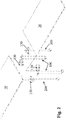
- Fig. 1 shows a first table construction (table) 10 and a separate second table construction (table) 20 prior to ganging the two tables to one another to form a combined, connected larger table.
- table 10 e.g., tables 10, 20
- tables 10, 20 are shown as being the same or substantially the same type of table in Fig. 1 , it will be appreciated that the table 10 can have a different construction than the table 20.
- the size and/or shape of one table can be different than the other table.
- each of the first and second tables 10, 20 has a rectangular shape; however, the tables can have square or round shapes or other shapes.
- one larger table can be ganged to one smaller table.
- Each of the first and second tables 10, 20 includes a tabletop 30 which is typically an at least substantially planar member and includes a plurality of legs that are coupled to an underside of the tabletop 30.
- the plurality of legs comprises two different types of legs and more specifically, each table 10, 20 includes at least one first leg 100 and at least one second leg 200.
- the first and second legs 100, 200 are configured to be releasably coupled to one another resulting in the ganging of the first and second tables 10 to form a single cleanly connected larger table.
- each first leg 100 is configured to allow for mating with one second leg 200 and vice versa; however, two of the same types of legs (i.e., either two first legs or two second legs) are not configured to mate with one another.
- the legs are arranged such that at least one leg 100 is paired with one second leg 200 to provide at least one attachment (ganging point) between the two tables 10, 20.
- each of the first and second tables 10, 20 includes a first end 22 and an opposite second end 24 and there are four legs in the four corresponding corners of each table 10, 20. More specifically, the second end 24 of the first table 10 is configured to be coupled (ganged) to the first end 22 of the second table 20. As a result, the second end 24 of the first table 10 has one first leg 100 in one corner (first corner) and one second leg 200 in the other corner (second corner) and the first end 22 of the second table 20 has one second leg 200 in one corner (opposite the first leg 100 at the second end 24 of the first table 10) and one first leg 100 in the other corner (opposite the second leg 200 at the second end 24 of the first table 10).
- the first ends 22 of the two tables 10, 20 have the same arrangement of legs and similarly, the second ends 24 of the two tables 10, 20 have the same arrangement of legs.
- each leg 100 includes an elongated body 102 that has a first end 104 and an opposite second end 106.
- the second end 106 can include a foot or a caster 108 to allow for easy movement of the table along a floor or the like.
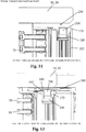
- the caster 108 can include a brake 109 ( Fig. 13 ) for locking the caster 108 and prevent a further rolling action, thereby locking the table in place.
- each leg 200 includes an elongated body 202 that has a first end 204 and an opposite second end 206.
- the second end 206 can include a foot or a caster 208 to allow for easy movement of the table along a floor or the like.
- the caster 208 can include a brake 209 ( Fig. 13 ) for locking the caster 208 and prevent a further rolling action, thereby locking the table in place.
- the first ends 102, 202 of the legs 100, 200 are coupled to the underside of the tabletop by conventional techniques, including the mechanical mount (bracket, etc.) described herein.
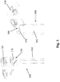
- Fig. 2 shows the arrangement of the legs 100, 200 at the second end 24 of the first table 10 and legs 200, 100 at the first end 22 of the second table 20. As shown, each leg 100 mates with one corresponding leg 200.
- the mechanical mount to attach the leg 100, 200 to the underside of the tabletop can be in the form of a casting 130 as shown.
- the casting 130 has a body 132 with a top surface 133 and an opposite bottom surface 134.
- the body 132 includes a base section 135 that includes a curved inner surface 136 (concave surface).
- the base section 135 has one or more mounting holes 137 which receive fasteners 50 as described below. Fasteners 50 can be threaded bolts or screws or other types of fasteners (nails, etc.).
- the body 132 includes additional mounting holes 138 for mounting the body 132 to the underside of the tabletop using additional fasteners 52.
- Fasteners 52 can be threaded screws or other types of fasteners including nails, bolts, etc.
- the top surface 133 is preferably a planar surface to allow the casting to be in flush contact with the underside of the tabletop.
- the body 132 can be a molded structure and can include reinforcing ribs 131 formed along the top surface 133 and the bottom surface 134.
- the body 132 can have a curved shape and in the illustrated embodiment, the body 132 has an oblong shape.
- the elongated bodies 102, 202 can have the same construction and be in the form of an extruded member.
- the elongated body 102, 202 is substantially hollow and includes a number of internal support structures that define different individual spaces (compartments) within the hollow interior of the body 102, 202.
- the hollow interior can include a first space 140 and a second space 150.
- the first space 140 has a generally circular shape, while the second space 150 has an irregular shape.
- a connecting block 160 is used to couple the casting 130 to the respective elongated body 102, 202.
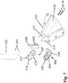
- the elongated body 102, 202 includes one or more holes 103 ( Fig. 7 ) that open into the second space 150.
- the connecting block 160 is configured to mate with and in particular, be slidingly inserted and contained within the second space 150.
- the connecting block 160 include one or more threaded holes 162.
- the connecting block 160 is inserted into the space 150 and the body 132 can include a stop or the like within the second space 150 such that when the connecting block 160 is received within the second space 150, the holes 162, 103 and 137 align with one another and fasteners 50 pass therethrough to securely attach the casting 130 to the body 102, 202.
- the curved inner surface 136 is complementary to the curved shape of the body 102, 202 such that the inner surface 136 and the curved outer surface of the body 102, 202 seat flush against one another. The casting 130 is thus fixed relative to the leg body 102, 202 and extends radially outward therefrom.
- Each of the first and second legs 100, 200 also includes a top cap 170 which mates with the first end 104, 204 of the respective leg 100, 200.
- a mechanical coupling can be formed between the top cap 170 and the leg 100, 200 and more specifically, a frictional fit (snap-fit) can be used to attach the top cap 170 to the respective leg 100, 200.
- the top cap 170 has a complementary shape to the first end 104, 204 since the top cap 170 is designed to close off this end but is also designed, as described herein, to provide for one respective ganging member.
- the illustrated top cap 170 thus has an oblong shape.
- the top cap 170 has a top surface 172 and an opposing bottom surface 174.
- the top cap 170 also has a through hole 175 which passes through the top cap 170 and in particular, a hollow boss 176 can extend downwardly from the bottom surface 174 with a bore 177 being formed therein being axially aligned with the through hole 175.
- a complete through hole extends through the complete top cap 170 from the top surface 172 to the bottom surface 174.
- the boss 176 is received within the first space 140 of the leg body 102, 202.
- the top cap 170 also has a mounting hole 178 formed therein for attaching the top cap 170 to the body 102, 202.
- the mounting hole 178 is axially aligned with the threaded boss 145 to allow the fastener 147 to extend therethrough so as to attach the top cap 170 to the leg body 102, 202.
- the top cap 170 thus covers and contains the connecting block 160. Once attached to the body leg 102, 202, the only opening (access point) defined in the top cap 170 is through the through hole 175.
- the first leg 100 includes a first ganging member 300 which is pivotally attached to the first leg 100 and more specifically, is pivotally attached to the top cap 170.
- the first ganging member 300 is a generally planar structure with a top surface or face 302 and an opposing bottom surface or face 304.
- the first ganging member 300 can be in the shape of a paddle and includes a first end 303 and an opposing second end 305.
- the second end 305 is of a greater size (wider) than the first end 303.
- the first and second ends 303, 305 can be curved (rounded).
- the curved second end 305 is convex in shape and designed to be received adjacent the curved inner surface 136 of the body 132.
- the first ganging member 300 includes an upstanding protrusion 310 which extends outwardly from the top surface 302.
- the upstanding protrusion 310 can have a circular shape and is configured to be received within a complementary opening that is formed in the underside of the tabletop of the respective table 10, 20.
- these openings (holes) at strategic set locations of the underside of the tabletop serve as locating and indicating features since only the first leg 100 and not the second leg 200 can be mated to such opening.
- the protrusion 310 serves also as a pivot axle in that the first ganging member 300 pivots about an axis that extends centrally through the protrusion 310.
- the protrusion 310 is thus configured to rotate within the opening in the underside of the tabletop; however, a frictional fit can be formed so that the first ganging member 300 does not quickly spin within the opening without any resistance. By having some resistance, the user can more easily control and position the first ganging member 300.
- a retaining member 320 is formed and is configured to allow the first ganging member 300 to be coupled to the top cap 170 such that the first ganging member 300 can rotate relative to the top cap 170.
- the retaining member 320 can be a mechanical coupler that rotatably couples the first ganging member 300 to the top cap 170.
- the retaining member 320 can be in the form of a clip or prongs that mate with complementary features formed internally within the hollow boss 176 resulting in the coupling between the two.
- an axis of rotation of the first ganging member 300 is defined through the protrusion 310 and the retaining member 320.
- An O-ring 333 ( Fig. 9 ) can be disposed between the underside of the first ganging member 300 and the top surface of the top cap 170 and more particularly, the O-ring 333 is disposed about the retaining member 320 the extends outwardly from the bottom surface.
- the O-ring 333 can create additional friction to prevent rapid, uncontrolled rotation of the first ganging member 300.
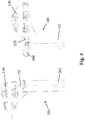
- the first ganging member 300 can be thought of as a pivoting arm that moves between a first position which is a stowed position ( Fig. 3 ) and a second position which is an extended, in-use position ( Fig. 4 ).
- the casting 130 is arranged to mate with leg body 102 at such a location and the body 132 has a height such that a space is formed above the top cap 170 which is sized to receive the first ganging member 300 and permit it to pivot between the first and second positions.
- the first ganging member 300 in the stowed position, the first ganging member 300 is disposed between the top cap 170 and the underside of the tabletop within such space.
- the top surface of the top cap 170 is thus below the top surface of the body 132 to create and define such space.
- the bottom surface 304 of the body of the first ganging member 300 includes a recessed portion (a recess) 340 that is disposed proximate the curved second end 305.
- a peripheral edge of the recessed portion 340 is a chamfered edge 342.
- a first coupling member 350 is disposed within the recessed portion 340 .
- the first coupling member 350 is, in the illustrated embodiment, a first magnetic member, such as a piece of metal (e.g., a metal washer) that is securely retained within the recessed portion 340.
- the first coupling member 350 (first magnetic member) is designed to mate with a complementary second magnetic member as described below.
- the first coupling member 350 is retained within the recessed portion 340 using any number of conventional techniques.
- the first coupling member 350 can have a planar construction as shown.
- Fig. 8 shows one exemplary second leg 200.
- the second leg 200 includes a second ganging member 230 which is complementary to the first ganging member 300 and is configured such that the first and second ganging members 230, 300 are coupled to one another, engage one another, interlock with one another or otherwise mate or are attracted to one another to cause a ganging between the first and second legs 100, 200 and thus between the two tables 10, 20.
- the second ganging member 230 comprises a number of parts that form an assembly.
- the second ganging member 230 can include a housing or casing in the form of a sleeve 240 which contains a second coupling member 250 which is complementary to the first coupling member 350.
- the sleeve 240 is a hollow structure that has an open first end 242.
- the sleeve 240 is shaped and sized to be received within the first space 140 that is formed in the body 202 of the second leg 200.
- a washer 245 can be used and inserted into the first space 140.
- the second coupling member 250 can be in the form of a second magnetic member that is designed to mate with the first magnetic member. More specifically, the second magnetic member can be in the form of a magnet that is contained within the sleeve 240.
- the top cap 170 is then mated to the first end of the body of the second leg 200.
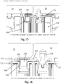
- the sleeve 240/magnet 250 combination is received within the hollow boss 176 that is itself received in the first space 140. It will be appreciated that the combined sleeve/magnet can move axially within the hollow boss 176 and can move between a first position (retracted position) ( Fig. 15 ) in which the sleeve/magnet are disposed at least substantially within the boss 176 and do not protrude above the top surface of the top cap 170 and a second position (extended position) ( Fig.16 ) in which the sleeve/magnet extend above the top surface of the top cap 170.
- Fig. 9 shows the first leg 100 with the first ganging member 300 in the first stowed position within the open space defined between the underside of the tabletop and the top cap 170.
- Fig. 10 shows the first ganging member 300 in the extended position. It will be appreciated that the curved end of the first ganging member 300 lies beyond the end of the table and therefore, the first coupling member 350 is accessible and spaced from the end of the table. To move between these two positions, the first ganging member 300 is pivoted about the pivot axis discussed herein.
- the underside of the first ganging member 300 can have a structure (finger locator) to assist in the user manually grasping the first ganging member 300 in the stowed position and then pivoting to the second position.
- Fig. 11 shows the second leg 200 with the second coupling member 250 of the second ganging member 230 in the first position in which the sleeve/magnet are retracted within the boss and a receiver space 199 is formed between the underside of the table and the top surface of the top cap 170.
- the combined sleeve/magnet can be thought of as being a pin structure that is magnetically attracted to the first coupling member 350 (metal washer or the like) formed in the first ganging member 300.
- the first coupling member 350 metal washer or the like
- the selection of the magnet and complementary metal structure are done in view of the intended application and exert a sufficient magnetic force that results in the two legs 100, 200 being coupled to one another.
- the two legs and two ganged tables are not easily and freely separable from one another but instead an applied force is required to overcome the magnetic force and cause the separation of the coupled legs 100, 200.
- To separate the two ganged tables the two tables are pulled laterally apart from one another.
- the top of the sleeve/magnet assembly contacts the chamfered edge 342 which acts as a cam and allows the first ganging member 300 to separate from the second ganging member 230.
- the combined sleeve/magnet is free to drop downward within the boss 176 in the top cap 170 and assume the retracted position ( Fig. 11 ).
- the combined sleeve/magnet (second coupling member) can be thought of as a pin that is at least partially received within the recessed portion 340 for locking the two ganging members 230, 300 to one another.
- One of the advantages of the present invention is that a clean seam is produced between the two ganged tables 10, 20 and thus, the ganging mechanism of the present invention not only provides a robust method for ganging tables together but also is an attractive system.
- the space 199 above the top cap 170 of the second leg 200 is sized to receive the first ganging member 300.
- the height of the first ganging member 300 can thus be equal to or slightly less than the height of this space 199.
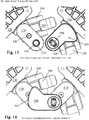
- Fig. 13 is a top view showing the tabletops removed from the two tables to show the positions of the first and second ganging members 300, 230 in the unganged position.
- Fig. 14 is a top view showing the first and second ganging members 300, 230 in the ganged position.
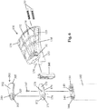
- Fig. 15 is side cross-sectional view showing the two tables 10, 20 in abutting relationship just prior to pivoting the first ganging member 300 into the receiver space 199 defined in the second leg 200. Thus, Fig. 15 also shows the unganged position.
- Fig. 16 shows the ganged position in which the two tables 10, 20 are ganged together and the first and second coupling members 350, 250 are coupled (e.g., via magnetic force).
- first and second coupling members 350, 250 can be switched in that the magnet 250 can be carried by the first ganging member 300 (within the recessed area 340) and the metal object (ferromagnetic material) can be disposed within the sleeve 240.
- the magnetic attraction remains the same as in the illustrated embodiment in that the sleeve 240 and metal object act as a pin that protrudes above the respective cap 170 into the recessed area 240 to thereby couple the two legs together and thereby gang one table to another.
- a biased plunger construction can be used in that the second leg 200 includes within the boss of the top cap 170 a biased plunger that seats therein similar to the sleeve 240.
- the biased plunger construction can be a spring loaded ball plunger that seats within the top cap 170 of the second leg 200 (the plunger can be normally biased in the extended position and when the swing arm makes initial contact causes a slight retraction of the plunger until the plunger aligns with the opening (recess 240) at which time it the biasing forces thereof cause it to travel into the opening.
- the plunger construction acts as a movable pin like the magnet/sleeve described herein.
- the plunger is configured to be received within an opening (like the recessed portion 240) formed in the underside of the swing arm of the first leg 100.
- an opening like the recessed portion 240
- the spring of the plunger causes the plunger to enter the opening, thereby coupling and locking the swing arm to this receiver portion of the second leg. This results in the tables to which the legs are mounted being ganged together.
- the leg of the present by design allows a user to attach two tops together with the same bracket underneath the table in essence you can have two tops with only six legs where normally a user would always need eight legs and thus, the present invention allows a user to save money.
- the teachings of the present invention thus provide the ability to permanently or at least until you took out the screws have a very long table up 144 inches using just six legs.
- ganging members based on magnetic attraction can be provided as an accessory instead of being integrally formed as part of the two legs 100, 200.
- the swing arm described herein can be mounted to the underside of a first table and the receiver portion (which includes a movable magnet pin structure) is mounted to the underside of the other table.
- the swing arm is thus pivotally attached to the underside of the table.
- the magnet pin structure can be part of a bracket that is mounted to the underside of the table and has a receiver space that receives the swing arm and allows the pin structure to be received within the recessed portion of the swing arm.
- the bracket can thus be similar to the top cap with the exception that the bracket has a portion that directly attaches to the underside of the table.
- the swing arm and magnet based pin are utilized as in the prior embodiment described herein with the exception that they are separate from the legs which can be mounted to the table at different locations.
- the bracket of the receiver portion can be an L-shaped bracket or U-shaped bracket in which a top leg thereof is mounted to the underside of the table and a parallel bottom leg is similar to the top cap in that it has a boss extending downwardly therefrom in which the sleeve/magnet 240, 250 are disposed identical to the previous embodiment (the receiver space is defined between the bottom leg and the underside of the table).
- the swing arm can be likewise mounted with a bracket (e.g., U-shaped) in which the top leg is mounted to the underside of the table and the bottom parallel leg has structure similar to the top cap in that it includes the boss 176 into which the retaining member is received and coupled to allow the pivoting of the swing arm.
- the swing arm is pivoted to the extended position and is received between the bottom leg of the bracket and the underside of the table.
- the pin magnet/sleeve
- the pin is drawn upward as described herein to lock the two ganging members together.
- the legs i.e., the first and second legs
- the legs can be used with other structures besides tables.
- the legs can be used with other support surface members which are to be detachable coupled (ganged) to one another.
- the legs of the present invention can be incorporated into benches, stools, seats, and other support structures which are desired to be releasably interlocked in a clean manner.
- first and second ganging members can be coupled directly to the table instead of the legs with one ganging member being coupled to the underside of one table and the other ganging member being coupled to the underside of the other table with the one ganging member be movable between a retracted position and an extended position.
- the two ganging members are coupled to one another by magnetic force (magnetic attraction).
- one ganging member can be a swing arm carrying a metal plate or a magnet and the other ganging member can be the other of metal plate and magnet.
- the legs 100, 200 can be part of a modular table system in that the legs 100, 200 that include the integral ganging mechanism can be attached to any number of different types/styles of tables.
- the tables include strategically placed locating marks (i.e., holes) that guide the assembler into correctly placing the first legs that include the pivotable swing arm and can include second locating marks that guide the placement of the second legs 200.
- the present invention thus offers a simple, modular table system having the advantages described herein. Any number of different materials can be used to form the structures of the legs including metals, plastics, etc.
- the elongated portions of the legs can be extruded parts and many of the other parts can be molded parts.
Landscapes
- Engineering & Computer Science (AREA)
- General Engineering & Computer Science (AREA)
- Mechanical Engineering (AREA)
- Furniture Connections (AREA)
- Rotary Switch, Piano Key Switch, And Lever Switch (AREA)
- Accommodation For Nursing Or Treatment Tables (AREA)
Claims (10)
- Mécanisme d'assemblage pour attacher de manière libérable un premier objet (10) à un second objet (20), comprenant :une première partie (100) qui est couplée au premier objet (10), la première partie (100) comprenant une partie mobile (300) qui porte un premier élément d'assemblage (300), la partie mobile (300) pouvant être positionnée entre une position repliée et une position étendue ; etune seconde partie (200) qui est couplée au second objet, la seconde partie comprenant une partie réceptrice qui reçoit la partie mobile (300) en position étendue, la seconde partie (200) comprenant un second élément d'assemblage (230) qui est configuré pour se coupler au premier élément d'assemblage (300) ayant pour résultat que le premier objet (10) est assemblé au second objet (20),dans lequel :les premier et second éléments d'assemblage (300, 230) sont couplés de manière libérable l'un à l'autre par attraction magnétique ;les première et seconde parties comprennent des premier et second pieds (100, 200) qui peuvent être montés sur les premier et second objets (10, 20), respectivement ;les premier et second objets (10, 20) comprennent des première et seconde tables et les pieds (100, 300) sont montés de manière fixe sur une partie inférieure des tables respectives (10, 20) ;caractérisé en ce quechaque pied comprend un corps allongé (102, 202) et un moulage (130) qui s'étend vers l'extérieur depuis le corps allongé et se monte sur la partie inférieure de la table respective (10, 20), le corps allongé étant une structure creuse qui est fermée à une extrémité supérieure à l'aide d'un capuchon supérieur (170) ; etune surface supérieure du moulage (130) est plus haute qu'une surface supérieure du capuchon supérieur (170) de manière à former un espace au-dessus du capuchon supérieur (170) et à proximité adjacente du moulage (130).
- Mécanisme d'assemblage selon la revendication 1, dans lequel les premier et second objets comprennent des tables séparées (10, 20).
- Mécanisme d'assemblage selon la revendication 1 ou 2, dans lequel le premier élément d'assemblage (300) comprend un bras pivotant (300) qui est disposé dans l'espace situé au-dessus du capuchon supérieur (170) du premier pied (100) et est fixé de manière pivotante au capuchon supérieur (170), le bras pivotant (300) ayant une surface inférieure qui comprend l'un parmi un substrat en métal et un aimant et le second élément d'assemblage (230) comprend une structure de broche formée de l'un parmi un aimant et un substrat en métal qui peut être déplacée axialement à l'intérieur d'une ouverture formée dans le capuchon supérieur, de sorte que, lorsque le bras pivotant (300) pivote dans la position étendue, la broche est tirée pour venir en prise avec le bras pivotant, couplant ainsi les premier et second pieds (100, 200) l'un à l'autre ayant pour résultat que la première table (10) est assemblée à la seconde table (20).
- Mécanisme d'assemblage selon la revendication 1, dans lequel le premier élément d'assemblage (300) comprend un bras oscillant (300) qui porte une plaque métallique et le second élément d'assemblage (230) comprend une broche qui porte un aimant de sorte que, lorsque le bras oscillant (300) est dans la position étendue, la broche est tirée pour venir en prise avec le bras oscillant, de manière à coupler ensemble les premier et second pieds (100, 200), ayant pour résultat l'assemblage des premier et second objets (10, 20).
- Mécanisme d'assemblage selon la revendication 4, dans lequel une partie inférieure de chacune des première et seconde tables comprend au moins un trou délibérément placé qui marque un emplacement au niveau duquel un premier pied (100) doit être monté.
- Mécanisme d'assemblage selon la revendication 5, dans lequel le bras oscillant (300) comprend une saillie (310) qui s'étend radialement vers l'extérieur depuis sa surface supérieure, la saillie (310) étant reçue dans le trou situé dans la partie inférieure de la table respective.
- Mécanisme d'assemblage selon la revendication 6, dans lequel un axe de pivotement du bras oscillant (300) passe à travers la saillie (310).
- Mécanisme d'assemblage selon la revendication 1, dans lequel chaque pied (100, 200) comprend un corps allongé (102, 202) et un moulage (300) qui s'étend vers l'extérieur depuis le corps allongé (102, 202) et se monte sur la partie inférieure de la table respective (10, 20), le corps allongé (102, 202) étant une structure creuse qui est fermée à une extrémité supérieure à l'aide d'un capuchon supérieur (170), dans lequel le capuchon supérieur (170) a une structure modulaire qui est configurée pour s'accoupler à la fois au premier élément d'assemblage (300) et au second élément d'assemblage (230).
- Mécanisme d'assemblage selon la revendication 8, dans lequel les première et seconde tables (10, 20) sont agencées de telle sorte qu'un premier pied (100) a une relation en vis-à-vis avec un seconde pied (200) pour permettre au premier élément d'assemblage (300) de se déplacer dans la position étendue et d'être couplé au second élément d'assemblage (230).
- Mécanisme d'assemblage selon la revendication 1, dans lequel la partie réceptrice comprend un espace formé entre la première partie (100) et le premier objet (10).
Priority Applications (1)
| Application Number | Priority Date | Filing Date | Title |
|---|---|---|---|
| EP19171644.8A EP3536192B1 (fr) | 2014-06-06 | 2015-05-29 | Mécanisme pour tables pouvant être accouplées |
Applications Claiming Priority (2)
| Application Number | Priority Date | Filing Date | Title |
|---|---|---|---|
| US14/297,775 US9402473B2 (en) | 2014-06-06 | 2014-06-06 | Mechanism for ganging tables |
| PCT/US2015/033261 WO2015187495A1 (fr) | 2014-06-06 | 2015-05-29 | Mécanisme pour tables pouvant être accouplées |
Related Child Applications (1)
| Application Number | Title | Priority Date | Filing Date |
|---|---|---|---|
| EP19171644.8A Division EP3536192B1 (fr) | 2014-06-06 | 2015-05-29 | Mécanisme pour tables pouvant être accouplées |
Publications (3)
| Publication Number | Publication Date |
|---|---|
| EP3151699A1 EP3151699A1 (fr) | 2017-04-12 |
| EP3151699A4 EP3151699A4 (fr) | 2018-03-14 |
| EP3151699B1 true EP3151699B1 (fr) | 2019-05-01 |
Family
ID=54767219
Family Applications (2)
| Application Number | Title | Priority Date | Filing Date |
|---|---|---|---|
| EP15803002.3A Not-in-force EP3151699B1 (fr) | 2014-06-06 | 2015-05-29 | Mécanisme pour tables pouvant être accouplées |
| EP19171644.8A Not-in-force EP3536192B1 (fr) | 2014-06-06 | 2015-05-29 | Mécanisme pour tables pouvant être accouplées |
Family Applications After (1)
| Application Number | Title | Priority Date | Filing Date |
|---|---|---|---|
| EP19171644.8A Not-in-force EP3536192B1 (fr) | 2014-06-06 | 2015-05-29 | Mécanisme pour tables pouvant être accouplées |
Country Status (6)
| Country | Link |
|---|---|
| US (1) | US9402473B2 (fr) |
| EP (2) | EP3151699B1 (fr) |
| CN (1) | CN106793867B (fr) |
| CA (1) | CA2948503C (fr) |
| MY (1) | MY193700A (fr) |
| WO (1) | WO2015187495A1 (fr) |
Families Citing this family (18)
| Publication number | Priority date | Publication date | Assignee | Title |
|---|---|---|---|---|
| US10034404B2 (en) * | 2014-11-10 | 2018-07-24 | Centrifyhealth, Llc | Interchangeable panel or plate for server case |
| US9560911B1 (en) * | 2015-08-06 | 2017-02-07 | Eleven23 Marketing, LLC | Configurable table |
| USD790961S1 (en) * | 2016-03-15 | 2017-07-04 | Plako Gmbh | Table connector |
| EP3539420A1 (fr) * | 2018-03-16 | 2019-09-18 | Eppendorf AG | Dispositif formant armoire de laboratoire destiné au stockage des échantillons de laboratoire à fermeture magnétique |
| DE102018208676A1 (de) * | 2018-06-01 | 2020-01-09 | Frank Maager | System zum Aufbau eines Möbels und zugehörige Tragstruktur |
| CN109303416B (zh) * | 2018-11-14 | 2021-06-08 | 邵雨坤 | 可重构讨论桌辅助拼接装置 |
| JP7272803B2 (ja) * | 2019-01-23 | 2023-05-12 | 株式会社オカムラ | 天板付什器 |
| US11040567B2 (en) * | 2019-01-24 | 2021-06-22 | Brian Schroeder | Reusable writing surface with magnetic legs |
| CN111168410B (zh) * | 2020-02-19 | 2025-04-01 | 浙江迈尔工具有限公司 | 拼接组合式工作台 |
| US11369192B2 (en) * | 2020-04-28 | 2022-06-28 | Daniel Grabowski | Floating table leg cap |
| WO2021255506A1 (fr) * | 2020-06-20 | 2021-12-23 | Robert Schwenke | Système de table extensible |
| CN112315187B (zh) * | 2020-10-14 | 2022-10-28 | 上海佳颐家具有限公司 | 一种桌子 |
| US11969081B2 (en) * | 2020-10-28 | 2024-04-30 | Quint Workspaces Llc | Connection assembly for connecting a support member to a work surface and corresponding method |
| JP7606849B2 (ja) * | 2020-10-29 | 2024-12-26 | 株式会社オカムラ | テーブル |
| CN112716142B (zh) * | 2020-12-25 | 2023-03-28 | 强恩逊(惠州)家居发展有限公司 | 人字旋转支架锁紧机构、人字旋转支架锁紧方法及电脑桌 |
| CN112773092B (zh) * | 2021-01-18 | 2022-01-28 | 北京金隅天坛家具股份有限公司 | 一种可自由拼接桌面的轨道式餐桌 |
| CN114396417B (zh) * | 2022-01-17 | 2023-06-20 | 广东华盛家具集团有限公司 | 一种便于多桌面拼接的装置和一种便于拼接的桌体 |
| CN114680467B (zh) * | 2022-04-18 | 2023-04-18 | 江苏省诚信教学设备有限公司 | 一种便于试验交流的可拼装教学课桌及拼装方法 |
Family Cites Families (17)
| Publication number | Priority date | Publication date | Assignee | Title |
|---|---|---|---|---|
| US2340864A (en) * | 1941-12-04 | 1944-02-08 | Carpenter Miles Harold | Fastening means for building construction |
| US3342147A (en) * | 1966-04-12 | 1967-09-19 | George Marshall Thomas | Modular table |
| DE3610232A1 (de) * | 1986-03-26 | 1987-10-01 | Hohenloher Spezialmoebel | Tisch, insbesondere konferenztisch |
| DE3835714A1 (de) * | 1988-10-20 | 1990-04-26 | Kusch Co Sitzmoebel | Verbindungsbeschlag fuer tisch-zwischenplatten |
| GB2303167B (en) * | 1995-07-12 | 1999-06-30 | Steelcase Inc | A mounting mechanism |
| US5794545A (en) * | 1997-02-14 | 1998-08-18 | Jami, Inc. | Linkable modular table system |
| US5934203A (en) * | 1997-09-19 | 1999-08-10 | Virco Mfg. Corporation | Table construction |
| US6048127A (en) * | 1998-10-15 | 2000-04-11 | Ditto Sales, Inc. | Furniture ganging device |
| DE10135921A1 (de) * | 2001-07-24 | 2003-02-06 | Dauphin Friedrich W Gmbh | Klapp-Tisch |
| DE10312269A1 (de) * | 2003-03-19 | 2004-09-30 | Drumm Gmbh | Magneto-mechanische Schließeinrichtung |
| US7226125B2 (en) * | 2004-04-16 | 2007-06-05 | Biofit Engineered Products | Convertible bench table with magnetic locks |
| DE102005043454B3 (de) * | 2005-09-13 | 2007-05-03 | Carl Zeiss Industrielle Messtechnik Gmbh | Wechseleinrichtung |
| EP1990549A1 (fr) * | 2007-05-08 | 2008-11-12 | Franz Baur | Moyen d'attache et procédé de fabrication d'une liaison entre un premier composant et un second |
| US8096244B1 (en) * | 2007-06-06 | 2012-01-17 | Nucraft Furniture Company | Modular conference table |
| CN101496676B (zh) * | 2008-02-02 | 2013-02-13 | 刘萍 | 一种可拆装和拼接使用的桌子 |
| US8359983B2 (en) * | 2011-06-02 | 2013-01-29 | Halcon Inc. | Adjustable table apparatus and method |
| CN203341301U (zh) * | 2013-07-01 | 2013-12-18 | 林再传 | 一种拼接型餐桌 |
-
2014
- 2014-06-06 US US14/297,775 patent/US9402473B2/en active Active
-
2015
- 2015-05-29 MY MYPI2016704473A patent/MY193700A/en unknown
- 2015-05-29 CN CN201580030161.8A patent/CN106793867B/zh not_active Expired - Fee Related
- 2015-05-29 CA CA2948503A patent/CA2948503C/fr not_active Expired - Fee Related
- 2015-05-29 EP EP15803002.3A patent/EP3151699B1/fr not_active Not-in-force
- 2015-05-29 EP EP19171644.8A patent/EP3536192B1/fr not_active Not-in-force
- 2015-05-29 WO PCT/US2015/033261 patent/WO2015187495A1/fr not_active Ceased
Non-Patent Citations (1)
| Title |
|---|
| None * |
Also Published As
| Publication number | Publication date |
|---|---|
| CA2948503A1 (fr) | 2015-12-10 |
| MY193700A (en) | 2022-10-25 |
| US9402473B2 (en) | 2016-08-02 |
| US20150351537A1 (en) | 2015-12-10 |
| EP3151699A4 (fr) | 2018-03-14 |
| EP3536192A1 (fr) | 2019-09-11 |
| CN106793867B (zh) | 2020-06-05 |
| EP3151699A1 (fr) | 2017-04-12 |
| WO2015187495A1 (fr) | 2015-12-10 |
| CA2948503C (fr) | 2018-10-09 |
| CN106793867A (zh) | 2017-05-31 |
| EP3536192B1 (fr) | 2020-10-28 |
Similar Documents
| Publication | Publication Date | Title |
|---|---|---|
| EP3151699B1 (fr) | Mécanisme pour tables pouvant être accouplées | |
| CN101843416B (zh) | 儿童餐椅的高度调整装置及该儿童餐椅 | |
| US8960104B2 (en) | Table | |
| US10758038B2 (en) | Article of furniture and method of using the same | |
| US8915197B2 (en) | Deck ledge table | |
| US5794902A (en) | Shelf bracket for use with a grooved shelf | |
| US12480539B2 (en) | Rapid-release anchor and fitting | |
| US20060032993A1 (en) | Tool used for removing and fitting a transmission gear box | |
| CA2447145C (fr) | Ensemble de fixation amovible de sections de chaise | |
| JP3225303U (ja) | ソケット台とそれを含むソケット置きコンポーネント | |
| JPH0910050A (ja) | 脚部の高さ調節装置 | |
| EP2630895B1 (fr) | Élément de fixation, d'utilisation spécifique dans des chaises-pupitres | |
| US7096533B2 (en) | Locking roller for an article of furniture | |
| HK1233144A1 (en) | Mechanism for ganging tables | |
| US12329287B2 (en) | Dining chair | |
| JP7563128B2 (ja) | 家具システム | |
| JP3204638U (ja) | 衝立の取付構造 | |
| CA2427128C (fr) | Mecanisme de reglage en hauteur pour structure de support pour bebe | |
| HK1233144B (zh) | 用於拼接桌的机构 | |
| JP7581789B2 (ja) | 家具システム | |
| JP4095517B2 (ja) | 物品支持システム及び軸部材固定具 | |
| JP7697746B1 (ja) | マグネットジョイントセット及びマグネットジョイント | |
| US20060249060A1 (en) | Height adjustable furniture component | |
| US10292459B2 (en) | Fastener | |
| US20030192927A1 (en) | Carrying assembly |
Legal Events
| Date | Code | Title | Description |
|---|---|---|---|
| STAA | Information on the status of an ep patent application or granted ep patent |
Free format text: STATUS: THE INTERNATIONAL PUBLICATION HAS BEEN MADE |
|
| PUAI | Public reference made under article 153(3) epc to a published international application that has entered the european phase |
Free format text: ORIGINAL CODE: 0009012 |
|
| STAA | Information on the status of an ep patent application or granted ep patent |
Free format text: STATUS: REQUEST FOR EXAMINATION WAS MADE |
|
| 17P | Request for examination filed |
Effective date: 20161124 |
|
| AK | Designated contracting states |
Kind code of ref document: A1 Designated state(s): AL AT BE BG CH CY CZ DE DK EE ES FI FR GB GR HR HU IE IS IT LI LT LU LV MC MK MT NL NO PL PT RO RS SE SI SK SM TR |
|
| AX | Request for extension of the european patent |
Extension state: BA ME |
|
| RIN1 | Information on inventor provided before grant (corrected) |
Inventor name: GRABOWSKI, DANIEL Inventor name: GRESHAM, DAVID Inventor name: COTTRELL, JOHN C. |
|
| DAV | Request for validation of the european patent (deleted) | ||
| DAX | Request for extension of the european patent (deleted) | ||
| A4 | Supplementary search report drawn up and despatched |
Effective date: 20180209 |
|
| RIC1 | Information provided on ipc code assigned before grant |
Ipc: A47B 87/00 20060101ALI20180205BHEP Ipc: A47B 13/00 20060101AFI20180205BHEP |
|
| REG | Reference to a national code |
Ref country code: DE Ref legal event code: R079 Ref document number: 602015029434 Country of ref document: DE Free format text: PREVIOUS MAIN CLASS: A47B0013000000 Ipc: A47B0013020000 |
|
| RIC1 | Information provided on ipc code assigned before grant |
Ipc: A47B 87/00 20060101ALI20181008BHEP Ipc: F16B 12/42 20060101ALI20181008BHEP Ipc: F16B 1/00 20060101ALI20181008BHEP Ipc: A47B 13/02 20060101AFI20181008BHEP |
|
| GRAP | Despatch of communication of intention to grant a patent |
Free format text: ORIGINAL CODE: EPIDOSNIGR1 |
|
| STAA | Information on the status of an ep patent application or granted ep patent |
Free format text: STATUS: GRANT OF PATENT IS INTENDED |
|
| INTG | Intention to grant announced |
Effective date: 20181119 |
|
| GRAS | Grant fee paid |
Free format text: ORIGINAL CODE: EPIDOSNIGR3 |
|
| GRAA | (expected) grant |
Free format text: ORIGINAL CODE: 0009210 |
|
| STAA | Information on the status of an ep patent application or granted ep patent |
Free format text: STATUS: THE PATENT HAS BEEN GRANTED |
|
| AK | Designated contracting states |
Kind code of ref document: B1 Designated state(s): AL AT BE BG CH CY CZ DE DK EE ES FI FR GB GR HR HU IE IS IT LI LT LU LV MC MK MT NL NO PL PT RO RS SE SI SK SM TR |
|
| REG | Reference to a national code |
Ref country code: GB Ref legal event code: FG4D |
|
| REG | Reference to a national code |
Ref country code: CH Ref legal event code: EP Ref country code: AT Ref legal event code: REF Ref document number: 1125757 Country of ref document: AT Kind code of ref document: T Effective date: 20190515 |
|
| REG | Reference to a national code |
Ref country code: DE Ref legal event code: R096 Ref document number: 602015029434 Country of ref document: DE |
|
| REG | Reference to a national code |
Ref country code: IE Ref legal event code: FG4D |
|
| REG | Reference to a national code |
Ref country code: NL Ref legal event code: MP Effective date: 20190501 |
|
| REG | Reference to a national code |
Ref country code: LT Ref legal event code: MG4D |
|
| PG25 | Lapsed in a contracting state [announced via postgrant information from national office to epo] |
Ref country code: ES Free format text: LAPSE BECAUSE OF FAILURE TO SUBMIT A TRANSLATION OF THE DESCRIPTION OR TO PAY THE FEE WITHIN THE PRESCRIBED TIME-LIMIT Effective date: 20190501 Ref country code: NL Free format text: LAPSE BECAUSE OF FAILURE TO SUBMIT A TRANSLATION OF THE DESCRIPTION OR TO PAY THE FEE WITHIN THE PRESCRIBED TIME-LIMIT Effective date: 20190501 Ref country code: LT Free format text: LAPSE BECAUSE OF FAILURE TO SUBMIT A TRANSLATION OF THE DESCRIPTION OR TO PAY THE FEE WITHIN THE PRESCRIBED TIME-LIMIT Effective date: 20190501 Ref country code: NO Free format text: LAPSE BECAUSE OF FAILURE TO SUBMIT A TRANSLATION OF THE DESCRIPTION OR TO PAY THE FEE WITHIN THE PRESCRIBED TIME-LIMIT Effective date: 20190801 Ref country code: HR Free format text: LAPSE BECAUSE OF FAILURE TO SUBMIT A TRANSLATION OF THE DESCRIPTION OR TO PAY THE FEE WITHIN THE PRESCRIBED TIME-LIMIT Effective date: 20190501 Ref country code: SE Free format text: LAPSE BECAUSE OF FAILURE TO SUBMIT A TRANSLATION OF THE DESCRIPTION OR TO PAY THE FEE WITHIN THE PRESCRIBED TIME-LIMIT Effective date: 20190501 Ref country code: FI Free format text: LAPSE BECAUSE OF FAILURE TO SUBMIT A TRANSLATION OF THE DESCRIPTION OR TO PAY THE FEE WITHIN THE PRESCRIBED TIME-LIMIT Effective date: 20190501 Ref country code: PT Free format text: LAPSE BECAUSE OF FAILURE TO SUBMIT A TRANSLATION OF THE DESCRIPTION OR TO PAY THE FEE WITHIN THE PRESCRIBED TIME-LIMIT Effective date: 20190901 Ref country code: AL Free format text: LAPSE BECAUSE OF FAILURE TO SUBMIT A TRANSLATION OF THE DESCRIPTION OR TO PAY THE FEE WITHIN THE PRESCRIBED TIME-LIMIT Effective date: 20190501 |
|
| PG25 | Lapsed in a contracting state [announced via postgrant information from national office to epo] |
Ref country code: LV Free format text: LAPSE BECAUSE OF FAILURE TO SUBMIT A TRANSLATION OF THE DESCRIPTION OR TO PAY THE FEE WITHIN THE PRESCRIBED TIME-LIMIT Effective date: 20190501 Ref country code: RS Free format text: LAPSE BECAUSE OF FAILURE TO SUBMIT A TRANSLATION OF THE DESCRIPTION OR TO PAY THE FEE WITHIN THE PRESCRIBED TIME-LIMIT Effective date: 20190501 Ref country code: GR Free format text: LAPSE BECAUSE OF FAILURE TO SUBMIT A TRANSLATION OF THE DESCRIPTION OR TO PAY THE FEE WITHIN THE PRESCRIBED TIME-LIMIT Effective date: 20190802 Ref country code: BG Free format text: LAPSE BECAUSE OF FAILURE TO SUBMIT A TRANSLATION OF THE DESCRIPTION OR TO PAY THE FEE WITHIN THE PRESCRIBED TIME-LIMIT Effective date: 20190801 |
|
| REG | Reference to a national code |
Ref country code: AT Ref legal event code: MK05 Ref document number: 1125757 Country of ref document: AT Kind code of ref document: T Effective date: 20190501 |
|
| REG | Reference to a national code |
Ref country code: CH Ref legal event code: PL |
|
| PG25 | Lapsed in a contracting state [announced via postgrant information from national office to epo] |
Ref country code: IS Free format text: LAPSE BECAUSE OF FAILURE TO SUBMIT A TRANSLATION OF THE DESCRIPTION OR TO PAY THE FEE WITHIN THE PRESCRIBED TIME-LIMIT Effective date: 20190901 |
|
| PG25 | Lapsed in a contracting state [announced via postgrant information from national office to epo] |
Ref country code: MC Free format text: LAPSE BECAUSE OF FAILURE TO SUBMIT A TRANSLATION OF THE DESCRIPTION OR TO PAY THE FEE WITHIN THE PRESCRIBED TIME-LIMIT Effective date: 20190501 Ref country code: CH Free format text: LAPSE BECAUSE OF NON-PAYMENT OF DUE FEES Effective date: 20190531 Ref country code: CZ Free format text: LAPSE BECAUSE OF FAILURE TO SUBMIT A TRANSLATION OF THE DESCRIPTION OR TO PAY THE FEE WITHIN THE PRESCRIBED TIME-LIMIT Effective date: 20190501 Ref country code: RO Free format text: LAPSE BECAUSE OF FAILURE TO SUBMIT A TRANSLATION OF THE DESCRIPTION OR TO PAY THE FEE WITHIN THE PRESCRIBED TIME-LIMIT Effective date: 20190501 Ref country code: SK Free format text: LAPSE BECAUSE OF FAILURE TO SUBMIT A TRANSLATION OF THE DESCRIPTION OR TO PAY THE FEE WITHIN THE PRESCRIBED TIME-LIMIT Effective date: 20190501 Ref country code: LI Free format text: LAPSE BECAUSE OF NON-PAYMENT OF DUE FEES Effective date: 20190531 Ref country code: EE Free format text: LAPSE BECAUSE OF FAILURE TO SUBMIT A TRANSLATION OF THE DESCRIPTION OR TO PAY THE FEE WITHIN THE PRESCRIBED TIME-LIMIT Effective date: 20190501 Ref country code: AT Free format text: LAPSE BECAUSE OF FAILURE TO SUBMIT A TRANSLATION OF THE DESCRIPTION OR TO PAY THE FEE WITHIN THE PRESCRIBED TIME-LIMIT Effective date: 20190501 Ref country code: DK Free format text: LAPSE BECAUSE OF FAILURE TO SUBMIT A TRANSLATION OF THE DESCRIPTION OR TO PAY THE FEE WITHIN THE PRESCRIBED TIME-LIMIT Effective date: 20190501 |
|
| REG | Reference to a national code |
Ref country code: DE Ref legal event code: R097 Ref document number: 602015029434 Country of ref document: DE |
|
| REG | Reference to a national code |
Ref country code: BE Ref legal event code: MM Effective date: 20190531 |
|
| PG25 | Lapsed in a contracting state [announced via postgrant information from national office to epo] |
Ref country code: LU Free format text: LAPSE BECAUSE OF NON-PAYMENT OF DUE FEES Effective date: 20190529 Ref country code: SM Free format text: LAPSE BECAUSE OF FAILURE TO SUBMIT A TRANSLATION OF THE DESCRIPTION OR TO PAY THE FEE WITHIN THE PRESCRIBED TIME-LIMIT Effective date: 20190501 Ref country code: IT Free format text: LAPSE BECAUSE OF FAILURE TO SUBMIT A TRANSLATION OF THE DESCRIPTION OR TO PAY THE FEE WITHIN THE PRESCRIBED TIME-LIMIT Effective date: 20190501 |
|
| PLBE | No opposition filed within time limit |
Free format text: ORIGINAL CODE: 0009261 |
|
| STAA | Information on the status of an ep patent application or granted ep patent |
Free format text: STATUS: NO OPPOSITION FILED WITHIN TIME LIMIT |
|
| PG25 | Lapsed in a contracting state [announced via postgrant information from national office to epo] |
Ref country code: TR Free format text: LAPSE BECAUSE OF FAILURE TO SUBMIT A TRANSLATION OF THE DESCRIPTION OR TO PAY THE FEE WITHIN THE PRESCRIBED TIME-LIMIT Effective date: 20190501 |
|
| 26N | No opposition filed |
Effective date: 20200204 |
|
| PG25 | Lapsed in a contracting state [announced via postgrant information from national office to epo] |
Ref country code: IE Free format text: LAPSE BECAUSE OF NON-PAYMENT OF DUE FEES Effective date: 20190529 Ref country code: PL Free format text: LAPSE BECAUSE OF FAILURE TO SUBMIT A TRANSLATION OF THE DESCRIPTION OR TO PAY THE FEE WITHIN THE PRESCRIBED TIME-LIMIT Effective date: 20190501 |
|
| PG25 | Lapsed in a contracting state [announced via postgrant information from national office to epo] |
Ref country code: BE Free format text: LAPSE BECAUSE OF NON-PAYMENT OF DUE FEES Effective date: 20190531 Ref country code: SI Free format text: LAPSE BECAUSE OF FAILURE TO SUBMIT A TRANSLATION OF THE DESCRIPTION OR TO PAY THE FEE WITHIN THE PRESCRIBED TIME-LIMIT Effective date: 20190501 |
|
| REG | Reference to a national code |
Ref country code: DE Ref legal event code: R082 Ref document number: 602015029434 Country of ref document: DE Representative=s name: HL KEMPNER PATENTANWALT, RECHTSANWALT, SOLICIT, DE |
|
| PG25 | Lapsed in a contracting state [announced via postgrant information from national office to epo] |
Ref country code: CY Free format text: LAPSE BECAUSE OF FAILURE TO SUBMIT A TRANSLATION OF THE DESCRIPTION OR TO PAY THE FEE WITHIN THE PRESCRIBED TIME-LIMIT Effective date: 20190501 |
|
| PG25 | Lapsed in a contracting state [announced via postgrant information from national office to epo] |
Ref country code: MT Free format text: LAPSE BECAUSE OF FAILURE TO SUBMIT A TRANSLATION OF THE DESCRIPTION OR TO PAY THE FEE WITHIN THE PRESCRIBED TIME-LIMIT Effective date: 20190501 Ref country code: HU Free format text: LAPSE BECAUSE OF FAILURE TO SUBMIT A TRANSLATION OF THE DESCRIPTION OR TO PAY THE FEE WITHIN THE PRESCRIBED TIME-LIMIT; INVALID AB INITIO Effective date: 20150529 |
|
| PGFP | Annual fee paid to national office [announced via postgrant information from national office to epo] |
Ref country code: DE Payment date: 20210413 Year of fee payment: 7 Ref country code: FR Payment date: 20210420 Year of fee payment: 7 |
|
| PGFP | Annual fee paid to national office [announced via postgrant information from national office to epo] |
Ref country code: GB Payment date: 20210428 Year of fee payment: 7 |
|
| PG25 | Lapsed in a contracting state [announced via postgrant information from national office to epo] |
Ref country code: MK Free format text: LAPSE BECAUSE OF FAILURE TO SUBMIT A TRANSLATION OF THE DESCRIPTION OR TO PAY THE FEE WITHIN THE PRESCRIBED TIME-LIMIT Effective date: 20190501 |
|
| REG | Reference to a national code |
Ref country code: DE Ref legal event code: R119 Ref document number: 602015029434 Country of ref document: DE |
|
| GBPC | Gb: european patent ceased through non-payment of renewal fee |
Effective date: 20220529 |
|
| PG25 | Lapsed in a contracting state [announced via postgrant information from national office to epo] |
Ref country code: FR Free format text: LAPSE BECAUSE OF NON-PAYMENT OF DUE FEES Effective date: 20220531 |
|
| PG25 | Lapsed in a contracting state [announced via postgrant information from national office to epo] |
Ref country code: GB Free format text: LAPSE BECAUSE OF NON-PAYMENT OF DUE FEES Effective date: 20220529 Ref country code: DE Free format text: LAPSE BECAUSE OF NON-PAYMENT OF DUE FEES Effective date: 20221201 |