EP3151966B1 - Testvorrichtungen und verfahren zur detektion eines zielanalyts - Google Patents
Testvorrichtungen und verfahren zur detektion eines zielanalyts Download PDFInfo
- Publication number
- EP3151966B1 EP3151966B1 EP15794988.4A EP15794988A EP3151966B1 EP 3151966 B1 EP3151966 B1 EP 3151966B1 EP 15794988 A EP15794988 A EP 15794988A EP 3151966 B1 EP3151966 B1 EP 3151966B1
- Authority
- EP
- European Patent Office
- Prior art keywords
- plunger
- detection zone
- receptacle
- membrane
- wick
- Prior art date
- Legal status (The legal status is an assumption and is not a legal conclusion. Google has not performed a legal analysis and makes no representation as to the accuracy of the status listed.)
- Active
Links
Images




Classifications
-
- B—PERFORMING OPERATIONS; TRANSPORTING
- B01—PHYSICAL OR CHEMICAL PROCESSES OR APPARATUS IN GENERAL
- B01L—CHEMICAL OR PHYSICAL LABORATORY APPARATUS FOR GENERAL USE
- B01L3/00—Containers or dishes for laboratory use, e.g. laboratory glassware; Droppers
- B01L3/50—Containers for the purpose of retaining a material to be analysed, e.g. test tubes
- B01L3/502—Containers for the purpose of retaining a material to be analysed, e.g. test tubes with fluid transport, e.g. in multi-compartment structures
- B01L3/5029—Containers for the purpose of retaining a material to be analysed, e.g. test tubes with fluid transport, e.g. in multi-compartment structures using swabs
-
- G—PHYSICS
- G01—MEASURING; TESTING
- G01N—INVESTIGATING OR ANALYSING MATERIALS BY DETERMINING THEIR CHEMICAL OR PHYSICAL PROPERTIES
- G01N21/00—Investigating or analysing materials by the use of optical means, i.e. using sub-millimetre waves, infrared, visible or ultraviolet light
- G01N21/75—Systems in which material is subjected to a chemical reaction, the progress or the result of the reaction being investigated
- G01N21/76—Chemiluminescence; Bioluminescence
-
- B—PERFORMING OPERATIONS; TRANSPORTING
- B01—PHYSICAL OR CHEMICAL PROCESSES OR APPARATUS IN GENERAL
- B01L—CHEMICAL OR PHYSICAL LABORATORY APPARATUS FOR GENERAL USE
- B01L3/00—Containers or dishes for laboratory use, e.g. laboratory glassware; Droppers
- B01L3/50—Containers for the purpose of retaining a material to be analysed, e.g. test tubes
- B01L3/502—Containers for the purpose of retaining a material to be analysed, e.g. test tubes with fluid transport, e.g. in multi-compartment structures
-
- G—PHYSICS
- G01—MEASURING; TESTING
- G01N—INVESTIGATING OR ANALYSING MATERIALS BY DETERMINING THEIR CHEMICAL OR PHYSICAL PROPERTIES
- G01N21/00—Investigating or analysing materials by the use of optical means, i.e. using sub-millimetre waves, infrared, visible or ultraviolet light
- G01N21/62—Systems in which the material investigated is excited whereby it emits light or causes a change in wavelength of the incident light
- G01N21/63—Systems in which the material investigated is excited whereby it emits light or causes a change in wavelength of the incident light optically excited
- G01N21/64—Fluorescence; Phosphorescence
-
- G—PHYSICS
- G01—MEASURING; TESTING
- G01N—INVESTIGATING OR ANALYSING MATERIALS BY DETERMINING THEIR CHEMICAL OR PHYSICAL PROPERTIES
- G01N21/00—Investigating or analysing materials by the use of optical means, i.e. using sub-millimetre waves, infrared, visible or ultraviolet light
- G01N21/75—Systems in which material is subjected to a chemical reaction, the progress or the result of the reaction being investigated
- G01N21/77—Systems in which material is subjected to a chemical reaction, the progress or the result of the reaction being investigated by observing the effect on a chemical indicator
- G01N21/78—Systems in which material is subjected to a chemical reaction, the progress or the result of the reaction being investigated by observing the effect on a chemical indicator producing a change of colour
-
- G—PHYSICS
- G01—MEASURING; TESTING
- G01N—INVESTIGATING OR ANALYSING MATERIALS BY DETERMINING THEIR CHEMICAL OR PHYSICAL PROPERTIES
- G01N33/00—Investigating or analysing materials by specific methods not covered by groups G01N1/00 - G01N31/00
- G01N33/48—Biological material, e.g. blood, urine; Haemocytometers
- G01N33/50—Chemical analysis of biological material, e.g. blood, urine; Testing involving biospecific ligand binding methods; Immunological testing
- G01N33/53—Immunoassay; Biospecific binding assay; Materials therefor
- G01N33/5302—Apparatus specially adapted for immunological test procedures
- G01N33/5304—Reaction vessels, e.g. agglutination plates
-
- B—PERFORMING OPERATIONS; TRANSPORTING
- B01—PHYSICAL OR CHEMICAL PROCESSES OR APPARATUS IN GENERAL
- B01L—CHEMICAL OR PHYSICAL LABORATORY APPARATUS FOR GENERAL USE
- B01L2200/00—Solutions for specific problems relating to chemical or physical laboratory apparatus
- B01L2200/16—Reagents, handling or storing thereof
-
- B—PERFORMING OPERATIONS; TRANSPORTING
- B01—PHYSICAL OR CHEMICAL PROCESSES OR APPARATUS IN GENERAL
- B01L—CHEMICAL OR PHYSICAL LABORATORY APPARATUS FOR GENERAL USE
- B01L2300/00—Additional constructional details
- B01L2300/08—Geometry, shape and general structure
- B01L2300/0809—Geometry, shape and general structure rectangular shaped
- B01L2300/0825—Test strips
-
- B—PERFORMING OPERATIONS; TRANSPORTING
- B01—PHYSICAL OR CHEMICAL PROCESSES OR APPARATUS IN GENERAL
- B01L—CHEMICAL OR PHYSICAL LABORATORY APPARATUS FOR GENERAL USE
- B01L2400/00—Moving or stopping fluids
- B01L2400/04—Moving fluids with specific forces or mechanical means
- B01L2400/0403—Moving fluids with specific forces or mechanical means specific forces
- B01L2400/0406—Moving fluids with specific forces or mechanical means specific forces capillary forces
-
- B—PERFORMING OPERATIONS; TRANSPORTING
- B01—PHYSICAL OR CHEMICAL PROCESSES OR APPARATUS IN GENERAL
- B01L—CHEMICAL OR PHYSICAL LABORATORY APPARATUS FOR GENERAL USE
- B01L2400/00—Moving or stopping fluids
- B01L2400/04—Moving fluids with specific forces or mechanical means
- B01L2400/0475—Moving fluids with specific forces or mechanical means specific mechanical means and fluid pressure
- B01L2400/0478—Moving fluids with specific forces or mechanical means specific mechanical means and fluid pressure pistons
Definitions
- Assay devices and methods of detecting target analytes are provided including quantitative test results, such as using chemiluminescence, fluorescence, colorimetry, etc.
- Lateral flow immunoassays are widely used in the food and medical diagnostics industries, as well as in simple point-of-care tests such as rapid strep tests and pregnancy tests.
- the lateral flow strip itself is usually a surfactant-infused nitrocellulose membrane, which contributes variability to the device results.
- Current technology for immunoassays is typically non-quantitative and lacks sensitivity.
- US5215102 A discloses a biological fluid collection and testing device, preferably a blood testing device.
- an assay device including a receptacle including a sample entry port; a plunger disposed within the receptacle and having a first surface; at least one reagent positioned below the plunger; a membrane attached to the first surface of the plunger; a wick providing capillary force; and a detection zone.
- the membrane includes a target conjugate zone in which a plurality of affinity components are disposed. A plurality of capture compounds are immobilized in a detection zone, which is located between the target conjugate zone and the wick.
- the assay device includes a receptacle including a surface and a sample entry port; a membrane attached to the surface of the receptacle; at least one reagent disposed in the receptacle; a plunger disposed within the receptacle and having a surface; and a detection zone in which a plurality of capture compounds are immobilized.
- the membrane has a wick providing capillary force. The detection zone is attached to the surface of the plunger and is located between the sample entry port and the wick.
- a method of detecting a target analyte includes (a) providing an assay device including a receptacle including a surface and a sample entry port; at least one reagent; a plunger disposed within the receptacle and having a surface wherein the at least one reagent is positioned below the plunger;; a membrane attached to the surface of the plunger, the surface of the receptacle, or both; and a detection zone in which a plurality of capture compounds are immobilized.
- the membrane includes a wick providing capillary force, and the detection zone is located between the sample entry port and the wick.
- the method further includes (b) providing a sample suspected to contain a target analyte; (c) adding the sample onto the membrane through the sample entry port; (d) allowing the sample to travel along the membrane until the sample reaches the detection zone; (e) immobilizing the target analyte through reaction of the target analyte with the capture compounds; (f) reacting the immobilized target analyte with the at least one reagent to generate a detectable signal; and (g) detecting the generated signal.
- any numerical range by endpoints is meant to include the endpoints of the range, all numbers within the range, and any narrower range within the stated range (e.g. 1 to 5 includes 1, 1.5, 2, 2.75, 3, 3.8, 4, and 5).
- all numbers expressing quantities or ingredients, measurement of properties and so forth used in the specification and embodiments are to be understood as being modified in all instances by the term "about.”
- the numerical parameters set forth in the foregoing specification and attached listing of embodiments can vary depending upon the desired properties sought to be obtained by those skilled in the art utilizing the teachings of the present disclosure. At the very least, and not as an attempt to limit the application of the doctrine of equivalents to the scope of the claimed embodiments, each numerical parameter should at least be construed in light of the number of reported significant digits and by applying ordinary rounding techniques.
- Analytes of interest for example bacteria, proteins, and other atoms or molecules, are often not inherently chemiluminescent, fluorescent, colored, etc., thus in order to achieve specific detection it is necessary to incorporate an affinity component into the assay device, such as an antibody, ligand or aptamer, that will allow the isolation of the analyte and its subsequent detection by a reaction.
- an affinity component such as an antibody, ligand or aptamer
- an assay device comprising:
- an assay device 100 comprises a receptacle 12 comprising a sample entry port 14; a plunger 16 disposed within the receptacle 12 and having a first surface 17; at least one reagent 18; a membrane 20 attached to the first surface 17 of the plunger 16, the membrane comprising a target conjugate zone 22 in which a plurality of affinity components 23 are disposed; a wick 24 providing capillary force; and a detection zone 26 in which a plurality of capture compounds 27 are immobilized.
- the detection zone 26 is located between the target conjugate zone 22 and the wick 24.
- the at least one reagent 18 is disposed in the receptacle 12 and the receptacle 12 further comprises a barrier 28 to separate the at least one reagent 18 from the plunger 16.
- the barrier comprises a metal foil or a pouch, for instance a pouch inside of which at least one reagent is disposed.
- the plunger is secured in the receptacle using a compression fitting, glue, or a ridge formed on the interior of the receptacle wall.
- the plunger 16 when a force F is applied to the plunger 16, the plunger 16 is configured to detach the detection zone 26 from being in fluid communication with the wick 24 and place the detection zone 26 in fluid communication with the at least one reagent 18.
- the plunger 16 comprises an end 30 configured to pierce the barrier 28, such as a pointed end.
- the configuration of the end of the plunger can vary depending on the thickness and type of material of the barrier.
- the barrier 28 is a foil pouch and the end 30 of the plunger 16 is rounded.
- an assay device comprising:
- the assay device 500 comprises a receptacle 12 comprising a surface 10 and a sample entry port 14; a membrane 20 attached to the surface 10 of the receptacle 12, the membrane 20 comprising a wick 24 providing capillary force; at least one reagent 18 disposed in the receptacle 12; a plunger 16 disposed within the receptacle 12 and having a surface 17; and a detection zone 26 in which a plurality of capture compounds 27 are immobilized, the detection zone 26 attached to the surface 17 of the plunger 16; wherein the detection zone 26 is located between the sample entry port 14 and the wick 24.
- a force F is applied to the plunger 16
- the detection zone 26 is moved from being in fluid communication with the membrane 20 to being in fluid communication with the at least one reagent 18.
- F i.e., depression of the plunger 16
- the below disclosure relates to both the first aspect and the second aspect provided above.
- the affinity components employed in the assay devices disclosed herein are not particularly limited as long as they will bind to the target analyte(s) of interest and are capable of participating in a detection reaction.
- the affinity components comprise any combination of a binding portion with a detection portion.
- the binding portion includes an antibody, a nucleotide aptamer, a peptide aptamer, or a ligand
- the detection portion includes an enzyme, a catalyst, and/or a molecule that provides an optical signal (e.g., a colorimetric signal, a fluorescent signal, or a luminescent signal).
- affinity components include for example and without limitation, horseradish peroxidase, luciferase, and alkaline phosphatase. Similar to the affinity components, the capture compounds are not limited as long as they will both remain fixed in place in the detection zone and bind to the target analyte(s) of interest.
- the capture compounds typically comprise an aptamer, a peptide, an antibody, a ligand, or a combination thereof.
- any captured analyte(s) and their bound affinity components are reacted with at least one reagent.
- the at least one reagent comprises hydrogen peroxide and/or luciferin.
- the at least one reagent comprises an aqueous solution.
- Luminol is often employed with chemiluminescent reactions involving hydrogen peroxide, thus in certain aspects of the disclosure, the barrier comprises a pouch and the pouch contains luminol.
- One suitable pouch comprises a cup structure having two plastic rings with a layer of foil affixed to and covering each ring, to form an enclosed cup.
- the pouch prevents the luminol and hydrogen peroxide from reacting prior to the addition of the captured target analyte, but once the pouch is pierced, the luminol is allowed to contact the hydrogen peroxide.
- the affinity components comprise an enzyme conjugated to an aptamer or an enzyme conjugated to an antibody.
- the skilled practitioner can identify aptamers and antibodies for specific target analytes of interest. Common enzymes include for example horseradish peroxidase and luciferase.
- the quantitative determination of a target analyte will result from the amount of conjugated horseradish peroxidase that reacts with luminol and hydrogen peroxide, for instance.
- An advantage of the use of the membrane in the receptacle is that it minimizes background signal by removing excess reaction catalyst (e.g., horseradish peroxidase) via continued travel of the catalyst in solution by capillary action towards the wick and away from the at least one reagent.
- the membrane optionally comprises one or more materials typically employed in flow assays, for example and without limitation, a fluid control film, a capillary fluid conductor (e.g., a stack of fluid control films), nitrocellulose, or other nonwoven membranes, such as membranes made of nylon, polysulfone, polyethersulfone, or polyvinylidenedifluoride (PVDF).
- a fluid control film e.g., a capillary fluid conductor (e.g., a stack of fluid control films)
- nitrocellulose or other nonwoven membranes, such as membranes made of nylon, polysulfone, polyethersulfone, or polyvinylidenedifluoride (PVDF).
- PVDF polyvinylidenedifluoride
- Suitable nitrocellulose and PVDF membranes for example, are known to the skilled practitioner, and are commercially available from suppliers such as Bio-Rad Laboratories, Inc. (Hercules, CA).
- the detection zone of a membrane optional
- a fluid control film comprises a sheet having at least one microstructure-bearing surface with one or more channels therein that permits, promotes, or facilitates control or directional flow of a liquid.
- Suitable fluid control films are described in U.S. Pat. Nos. 5,514,120 ; 5,728,446 ; 6,080,243 ; and 6,290,685 .
- Fluid control films are typically in the form of sheets or films rather than a mass of fibers.
- the channels of fluid control films provide more effective liquid flow than is generally achieved with webs, foam, or tows formed from fibers.
- the walls of channels formed in fibers will exhibit relatively random undulations and complex surfaces that interfere with flow of liquid through the channels.
- the channels are precisely replicated from a predetermined pattern and form a series of individual open capillary channels that extend along a major surface.
- These microreplicated channels formed in sheets, films, or tubes are preferably uniform and regular along substantially each channel length and more preferably from channel to channel. Fluid typically wicks up fluid control films a distance of about 2.5 inches (6.35 cm) within approximately 15 seconds. Advantages of employing a fluid control film as compared to a nonwoven membrane include a more even flow path, and thus more reproducible results.
- Fluid control films can be formed from any thermoplastic materials suitable for casting, or embossing including, for example, polyolefins, polyesters, polyamides, poly(vinyl chloride), polyether esters, polyimides, polyesteramide, polyacrylates, polyvinylacetate, hydrolyzed derivatives of polyvinylacetate, etc., or combinations thereof.
- Polyolefins are commonly employed, particularly polyethylene or polypropylene, blends and/or copolymers thereof, and copolymers of propylene and/or ethylene with minor proportions of other monomers, such as vinyl acetate or acrylates such as methyl and butylacrylate.
- Polyolefins exhibit excellent physical properties, ease of processing, and typically lower cost than other thermoplastic materials having similar characteristics.
- fluid control films can be cast from thermosets (curable resin materials) such as polyurethanes, acrylates, epoxies and silicones, and cured by exposure to heat or UV or E-beam radiation, or moisture. These materials may contain various additives including surface energy modifiers (such as surfactants and hydrophilic polymers), plasticizers, antioxidants, pigments, release agents, antistatic agents and the like. Suitable fluid control films also can be manufactured using pressure sensitive adhesive materials. In some cases the channels may be formed using inorganic materials (e.g., glass, ceramics, or metals). Preferably, the fluid control film substantially retains its geometry and surface characteristics upon exposure to liquids.
- the plunger of the assay device further comprises a second surface opposite the first surface and an end in communication with the first surface and the second surface, wherein the membrane is in contact with the end and with the second surface.
- Figure 1A illustrates a second surface 29 of the plunger 16 opposite the first surface 17 of the plunger 16 and an end 30 in communication with the first surface 17 and the second surface 29, wherein the membrane 20 is in contact with the end 30 and with the second surface 29.
- the membrane 20 comprises a U-shape around the plunger 16.
- Other shapes of the membrane are also contemplated, such as a V-shape, a squared-off U shape, and the like.
- the detection zone of the membrane is located at the end of the plunger.
- having a detection zone 26 located at the end 30 of the plunger 16 places the detection zone in relatively close proximity to the at least one reagent.
- the receptacle 12 comprises a test tube or a shape similar to a test tube.
- the assay device further includes a component (not shown) for assisting in piercing a barrier, for instance a shuttle as described in published international patent application WO 97/23596 .
- the component includes one or more of: a pointed end, at least one projection on the end, and at least one aperture in a surface of the component.
- a pointed end Typically, such a component would be advantageously employed when the end of the plunger is rounded or squared-off or the detection zone is located at the end of the plunger.
- An exemplary configuration of an assay device having such a component includes the component disposed between the bottom of the plunger and the barrier above the reagent solution.
- the component may be separately movable to break the barrier, or may be attached to the plunger so that when the plunger is manipulated the component pierces the barrier in advance of the plunger reaching the barrier.
- the component is coated with, or otherwise contains, a solid reagent to be added to the reaction mixture when the component breaks the barrier and comes into contact with the reagent solution.
- the membrane further comprises a control line disposed between the wick and the detection zone, the control line comprising a generic capture compound.
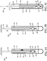
- the assay device 300 is illustrated to include a control line 32 on the membrane 20 between the wick 24 and the detection zone 26.
- the generic capture compound typically provides a color change when excess affinity component reacts with the generic capture compound.
- the control line may be easily viewed through a window 34, which allows a user to determine visibly if the sample has traveled past the detection zone and any captured target analyte is ready to be detected.
- the wick 24 (all or part) could be treated with a weakly buffered solution of a pH indicator.
- bromophenol blue undergoes a yellow to blue transition as the pH increases from 3 to 5.
- the appearance of a blue color will function as a sign the sample is ready for detection of any captured target analyte.
- Figures 3A-3C and 2A-2C further illustrate an assay device 300 and an assay device 200, respectively, including a plunger 16 that contains a threaded lower section 36.
- the threaded lower section 36 is mounted to an aligner 38 connected to a wall 13 of the receptacle 12 so that when the plunger 16 is rotated about its vertical axis a lower portion 40 of the membrane 20 does not rotate and the resultant tearing force breaks the lower portion 40 apart from the rest of the membrane 20.
- the aligner 38 is connected to the wall 13 in such a manner that it can move vertically, for instance with a protrusion in a slot in the wall (not shown), enabling the lower portion 40 to move downwards with the rotation of the threaded lower section 36 of the plunger 16, creating a physical gap in the membrane 20.
- the lower portion 40 is able to break the barrier 28 and interact with the at least one reagent 18; however, the break in the membrane 20 prevents any reaction fluid from travelling up to the wick 24 where any excess affinity component 23 has been retained.
- the assay device 400 includes a receptacle 12 containing a plunger 16 and a plunger sleeve 19 disposed within the receptacle 12.
- the device comprises a membrane 20 attached to an exterior surface 15 of the plunger sleeve 19.
- the plunger sleeve 19 is configured to define an opening 42 in a portion of the plunger sleeve 19 adjacent to the detection zone 26 of the membrane 20.
- the plunger sleeve 19 is secured in the receptacle 12 in this embodiment by being mounted to an aligner 38 connected to a wall 13 of the receptacle 12.
- the aligner 38 is connected to the wall 13 in such a manner that it can move vertically, such as being in communication with a vertical slot in the wall (not shown).
- the detection zone 26 is attached to a surface of the plunger 16.
- a plurality of capture compounds 27 are immobilized on the detection zone 26. As shown in Figure 4B , when the plunger 16 is rotated, only the detection zone 26 of the membrane 20 rotates and the resultant tearing force breaks the detection zone 26 apart from the rest of the membrane 20 and moves the detection zone 26 into the interior of the plunger sleeve 19.
- the plunger 16 may also be used to pierce a barrier in which the barrier comprises a pouch, and thus enable the simultaneous addition of extra components to the at least one reagent 18.
- the membrane 20 is shown arranged with the wick 24 at the bottom of the membrane 20 and a sample entry port (not shown) at the top. In this arrangement the sample fluid flows downwards.
- the assay device 400 can be simply modified so that the sample entry port is placed where the wick 24 is shown in Figures 4A-4B with the wick 24 to be relocated to a position above the detection zone 26.
- Such a device functions as a dipstick membrane, a common method in which the lower end of the membrane is immersed in the test solution. Potential sample overfilling is prevented because any excess sample added would flow back out of the port.
- the plunger 16 when the plunger 16 is rotated within the receptacle 12, the plunger 16 is configured to detach the detection zone 26 from being in fluid communication with the wick 24.
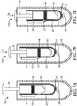
- the plunger 16 comprises a spring 44, wherein when the plunger 16 is depressed, the spring 44 engages with the membrane 20 at the detection zone 26 and the spring 44 expands to detach the detection zone 26 (on which a plurality of capture compounds 27 are immobilized) from being in fluid communication with the wick 24 and to place the detection zone 26 in fluid communication with the at least one reagent 18.
- an assay device 700 is provided.
- the plunger 16 comprises a spring 44, wherein when the plunger 16 is depressed, the spring 44 engages with the membrane 20 and the spring 44 expands to form a break in the membrane 20 at portion 21 to prevent the detection zone 26 from continuing to be in fluid communication with the wick 24.
- the detection zone 26 (on which a plurality of capture compounds 27 are immobilized) is placed in fluid communication with the at least one reagent 18.
- the break in the membrane 20 at portion 21 minimizes fluid flow of the at least one reagent towards the wick 24, to thereby minimize background signal during detection.
- the at least one reagent is disposed inside the plunger, and the plunger is configured to release a portion of the at least one reagent to place the portion of the at least one reagent in fluid communication with the detection zone.
- the plunger is configured to release a portion of the at least one reagent to place the portion of the at least one reagent in fluid communication with the detection zone.
- a portion of the receptacle is opaque and a portion of the receptacle is transparent to light.
- a method for detection of a target analyte comprising:
- the providing of the sample further comprises adding a plurality of affinity components to the sample to conjugate any target analyte
- the membrane further comprises a target conjugate zone in which a plurality of affinity components are disposed, wherein the target conjugate zone is located between the sample entry port and the detection zone.
- the detection zone is attached to the surface of the plunger and/or attached to the surface of the receptacle.
- the reacting further comprises applying force to the plunger to detach the detection zone from being in fluid communication with the wick and place the detection zone in fluid communication with the at least one reagent.
- applying force to the plunger typically comprises rotating the plunger, depressing the plunger, or rotating the plunger followed by depressing the plunger.
- the generated signal comprises luminescence and the detecting comprises using a luminometer to measure the luminescence.
- the generated signal comprises fluorescence and the detecting comprises using a fluorimeter, and in a further embodiment the generated signal comprises a color change and the detecting comprises using a colorimeter.
- the detecting further comprises quantifying the luminescence, fluorescence, or color change.
- Aptamers that bind specifically to Penicillin G are conjugated with horseradish peroxidase (HRP) and deposited on a fluid transport film affixed to the surface of the plunger. Capture antibodies to Penicillin G are deposited on the detection zone.
- Luminol is contained within a foil pouch positioned below the plunger and separating the plunger from a reagent solution containing hydrogen peroxide and, optionally, a surfactant. A 100 ⁇ L aliquot of the sample solution is introduced via a pipet through the sample entry port of the receptacle, and allowed to wick along the fluid transport film until it reaches the wick on the other side, typically 5 minutes.
- any Penicillin G present in the sample has sufficient time to react with the HRP-conjugated aptamers, travel along the film and then bind to the capture antibody where it will be retained in the detection zone.
- the plunger is depressed, puncturing the foil seal and allowing luminol contained within the pouch to contact the reagent solution.
- Any HRP retained in the detection zone facilitates the oxidation of luminol by hydrogen peroxide and generates 3-aminophthalate with the emission of light. The light is measured by a hand-held luminometer such as the 3M CLEAN-TRACE luminometer (3M Company, St. Paul, MN).
- Aptamers that bind specifically to Penicillin G are conjugated with horseradish peroxidase (HRP) and deposited on a fluid transport film affixed to the surface of the plunger. Capture antibodies to Penicillin G are deposited on the detection zone.
- ABTS 2,2'-azinobis [3-ethylbenzothiazoline-6-sulfonic acid]-diammonium salt
- a foil pouch positioned below the plunger and separating the plunger from a reagent solution containing hydrogen peroxide and, optionally, a surfactant.
- a 200 ⁇ L aliquot of the sample solution is introduced via a pipet through the sample entry port of the receptacle, and allowed to wick along the fluid transport film until it reaches the wick on the other side, typically 5 minutes.
- any Penicillin G present in the sample has sufficient time to react with the HRP-conjugated aptamers, travel along the film and then bind to the capture antibody where it will be retained in the detection zone.
- the plunger is depressed, puncturing the foil seal and allowing the ABTS contained within the pouch to contact the reagent solution.
- HRP retained in the detection zone oxidizes the colorless ABTS to its blue radical cation.
- the intensity of the blue color can be assessed visually by comparison with a color chart, or with a colorimeter such as the 3M CLEAN-TRACE colorimeter (3M Company, St. Paul, MN).
- Aptamers that bind specifically to Penicillin G are conjugated with horseradish peroxidase (HRP) and deposited on a fluid transport film affixed to the surface of the plunger. Capture antibodies to Penicillin G are deposited on the detection zone.
- ADHP (10-acetyl-3,7-dihydroxyphenoxazine) is contained within a foil pouch positioned below the plunger and separating the plunger from a reagent solution containing hydrogen peroxide and, optionally, a surfactant. A 250 ⁇ L aliquot of the sample solution is introduced via a pipet through the sample entry port of the receptacle, and allowed to wick along the fluid transport film until it reaches the wick on the other side, typically 5 minutes.
- any Penicillin G present in the sample has sufficient time to react with the HRP-conjugated aptamers, travel along the film and then bind to the capture antibody where it will be retained in the detection zone.
- the plunger is depressed, puncturing the foil seal and allowing the ADHP contained within the pouch to contact the reagent solution.
- HRP retained in the detection zone oxidizes the nonfluorescent ADHP to highly fluorescent resorufin.
- the intensity of the fluorescence can be assessed visually by irradiation with a standard UV lamp, or preferably with a fluorimeter using an excitation wavelength at of ⁇ 570 nm and emission of ⁇ 585nm.
- Aptamers that bind specifically to Penicillin G are conjugated with horseradish peroxidase (HRP) and deposited on a fluid transport film affixed to the surface of the plunger. Capture antibodies to Penicillin G are deposited on the detection zone.
- Luminol is contained within a foil pouch positioned below the plunger and separating the plunger from a reagent solution containing hydrogen peroxide and, optionally, a surfactant. A 100 ⁇ L aliquot of the sample solution is introduced via a pipet through the sample entry port of the receptacle, and allowed to wick along the fluid transport film until it reaches the wick on the other side, typically 5 minutes.
- any Penicillin G present in the sample has sufficient time to react with the HRP-conjugated aptamers, travel along the film and then bind to the capture antibody where it will be retained in the detection zone.
- a 1 mL aliquot of pH 7 buffer is then added through the sample entry port in order to rinse the fluid transport film and detection zone of excess HRP-conjugated antibodies.
- the plunger is depressed, puncturing the foil seal and allowing luminol contained within the pouch to contact the reagent solution.
- Any HRP retained in the detection zone facilitates the oxidation of luminol by hydrogen peroxide and generates 3-aminophthalate with the emission of light. The light is measured by a hand-held luminometer such as the 3M CLEAN-TRACE luminometer (3M Company, St. Paul, MN).
- Aptamers that bind specifically to Penicillin G are conjugated with horseradish peroxidase (HRP) and deposited on a fluid transport film affixed to the surface of the plunger. Capture antibodies to Penicillin G are deposited on the detection zone.
- ABTS 2,2'-azinobis [3-ethylbenzothiazoline-6-sulfonic acid]-diammonium salt
- a foil pouch positioned below the plunger and separating the plunger from a reagent solution containing hydrogen peroxide and, optionally, a surfactant.
- a 200 ⁇ L aliquot of the sample solution is introduced via a pipet through the sample entry port of the receptacle, and allowed to wick along the fluid transport film until it reaches the wick on the other side, typically 5 minutes. During this time, any Penicillin G present in the sample has sufficient time to react with the HRP-conjugated aptamers, travel along the film and then bind to the capture antibody where it will be retained in the detection zone.
- a 1 mL aliquot of pH 7 buffer is then added through the sample entry port in order to rinse the fluid transport film and detection zone of excess HRP-conjugated antibodies. After 5 minutes, the plunger is depressed, puncturing the foil seal and allowing the ABTS contained within the pouch to contact the reagent solution.
- HRP retained in the detection zone oxidizes the colorless ABTS to its blue radical cation.
- the intensity of the blue color can be assessed visually by comparison with a color chart, or with a colorimeter such as the 3M CLEAN-TRACE colorimeter (3M Company, St. Paul, MN).
- Aptamers that bind specifically to Penicillin G are conjugated with horseradish peroxidase (HRP) and deposited on a fluid transport film affixed to the surface of the plunger. Capture antibodies to Penicillin G are deposited on the detection zone.
- ADHP (10-acetyl-3,7-dihydroxyphenoxazine) is contained within a foil pouch positioned below the plunger and separating the plunger from a reagent solution containing hydrogen peroxide and, optionally, a surfactant. A 250 ⁇ L aliquot of the sample solution is introduced via a pipet through the sample entry port of the receptacle, and allowed to wick along the fluid transport film until it reaches the wick on the other side, typically 5 minutes.
- any Penicillin G present in the sample has sufficient time to react with the HRP-conjugated aptamers, travel along the film and then bind to the capture antibody where it will be retained in the detection zone.
- a 1 mL aliquot of pH 7 buffer is then added through the sample entry port in order to rinse the fluid transport film and detection zone of excess HRP-conjugated antibodies.
- the plunger is depressed, puncturing the foil seal and allowing the ADHP contained within the pouch to contact the reagent solution.
- HRP retained in the detection zone oxidizes the nonfluorescent ADHP to highly fluorescent resorufin.
- the intensity of the fluorescence can be assessed visually by irradiation with a standard UV lamp, or preferably with a fluorimeter using an excitation wavelength at of ⁇ 570 nm and emission of ⁇ 585nm.
- Antibodies to clostridium difficile as described in U.S. Patent No. 8,697,374 are conjugated with horseradish peroxidase (HRP) and deposited on a nitrocellulose membrane affixed to the surface of the plunger. Capture antibodies to clostridium difficile are deposited on the detection zone.
- Luminol is contained within a foil pouch positioned below the plunger and separating the plunger from a reagent solution containing hydrogen peroxide and, optionally, a surfactant.
- a 100 ⁇ L aliquot of the sample solution is introduced via a pipet through the sample entry port of the receptacle, and allowed to wick along the fluid transport film until it reaches the wick on the other side. During this time, any c.
- the plunger is rotated one full turn to cause a break in the fluid path of the membrane. The plunger is then depressed, puncturing the foil seal and allowing luminol contained within the pouch to contact the reagent solution. Any HRP retained in the detection zone facilitates the oxidation of luminol by hydrogen peroxide and generates 3-aminophthalate with the emission of light. The light is measured by a hand-held luminometer such as the 3M CLEAN-TRACE luminometer.
- Antibodies to clostridium difficile as described in U.S. Patent No. 8,697,374 are conjugated with horseradish peroxidase (HRP) and deposited on a nitrocellulose membrane affixed to the surface of the plunger. Capture antibodies to clostridium difficile are deposited on the detection zone.
- Luminol is contained within a foil pouch positioned below the plunger and separating the plunger from a reagent solution containing hydrogen peroxide and, optionally, a surfactant.
- a 100 ⁇ L aliquot of the sample solution is introduced via a pipet through the sample entry port of the receptacle, and allowed to wick along the fluid transport film until it reaches the wick on the other side. During this time, any c.
- Antibodies to clostridium difficile as described in U.S. Patent No. 8,697,374 are conjugated with horseradish peroxidase (HRP) and deposited on a nitrocellulose membrane affixed to the surface of the plunger. Capture antibodies to clostridium difficile are deposited on the detection zone.
- Luminol is contained within a foil pouch positioned below the plunger and separating the plunger from a reagent solution containing hydrogen peroxide and, optionally, a surfactant.
- a 100 ⁇ L aliquot of the sample solution is introduced via a pipet through the sample entry port of the receptacle, and allowed to wick along the fluid transport film until it reaches the wick on the other side. During this time, any c.
- Antibodies to clostridium difficile as described in U.S. Patent No. 8,697,374 are conjugated with horseradish peroxidase (HRP) and deposited on a nitrocellulose membrane affixed to the surface of the plunger. Capture antibodies to clostridium difficile are deposited on the detection zone.
- Luminol is contained within a foil pouch positioned below the plunger and separating the plunger from a reagent solution containing hydrogen peroxide and, optionally, a surfactant.
- a 100 ⁇ L aliquot of the sample solution is introduced via a pipet through the sample entry port of the receptacle, and allowed to wick along the fluid transport film until it reaches the wick on the other side. During this time, any c.
- Antibodies to clostridium difficile as described in U.S. Patent No. 8,697,374 are conjugated with horseradish peroxidase (HRP) and deposited on a nitrocellulose membrane affixed to the surface of the plunger. Capture antibodies to clostridium difficile are deposited on the detection zone.
- ABTS 2,2'-azinobis [3-ethylbenzothiazoline-6-sulfonic acid]-diammonium salt
- ABTS 2,2'-azinobis [3-ethylbenzothiazoline-6-sulfonic acid]-diammonium salt
- a 400 ⁇ L aliquot of the sample solution is introduced via a pipet through the sample entry port of the receptacle, and allowed to wick along the fluid transport film until it reaches the wick on the other side.
- any c. diff. present in the sample has sufficient time to react with the HRP-conjugated antibodies, travel along the film and then bind to the capture antibody where it will be retained in the detection zone.
- the plunger is rotated one full turn to cause a break in the fluid path of the membrane. The plunger is then depressed, puncturing the foil seal and allowing ABTS contained within the pouch to contact the reagent solution.
- HRP retained in the detection zone oxidizes the colorless ABTS to its blue radical cation. The intensity of the blue color can be assessed visually by comparison with a color chart, or with a colorimeter such as the 3M CLEAN-TRACE Colorimeter.
- Antibodies to clostridium difficile as described in U.S. Patent No. 8,697,374 are conjugated with horseradish peroxidase (HRP) and deposited on a nitrocellulose membrane affixed to the surface of the plunger. Capture antibodies to clostridium difficile are deposited on the detection zone.
- ADHP (10-acetyl-3,7-dihydroxyphenoxazine) is contained within a foil pouch positioned below the plunger and separating the plunger from a reagent solution containing hydrogen peroxide and, optionally, a surfactant.
- a 800 ⁇ L aliquot of the sample solution is introduced via a pipet through the sample entry port of the receptacle, and allowed to wick along the fluid transport film until it reaches the wick on the other side.
- any c. diff. present in the sample has sufficient time to react with the HRP-conjugated antibodies, travel along the film and then bind to the capture antibody where it will be retained in the detection zone.
- the plunger is rotated one full turn to cause a break in the fluid path of the membrane. The plunger is then depressed, puncturing the foil seal and allowing ADHP contained within the pouch to contact the reagent solution.
- HRP retained in the detection zone oxidizes the nonfluorescent ADHP to highly fluorescent resorufin.
- the intensity of the fluorescence can be assessed visually by irradiation with a standard UV lamp, or preferably with a fluorimeter using an excitation wavelength at of ⁇ 570 nm and emission of ⁇ 585nm.
- Antibodies to clostridium difficile as described in U.S. Patent No. 8,697,374 are conjugated with horseradish peroxidase (HRP) and deposited on a nitrocellulose membrane affixed to the surface of the plunger. Capture antibodies to clostridium difficile are deposited on the detection zone.
- Luminol is contained within a foil pouch positioned below the plunger and separating the plunger from a reagent solution containing hydrogen peroxide and, optionally, a surfactant.
- the wick contains a small amount of bromophenol blue, in its yellow, acid form.
- a 250 ⁇ L aliquot of the sample solution is mixed with 1 mL of pH 7 buffer and introduced via a pipet through the sample entry port of the receptacle, and allowed to wick along the fluid transport film until it reaches the wick on the other side. This is demonstrated by the appearance of a blue color (due to bromophenol blue) on the wick which may be visualized through the window.
- any c. diff. present in the sample has sufficient time to react with the HRP-conjugated antibodies, travel along the film and then bind to the capture antibody where it will be retained in the detection zone.
- the plunger is rotated one full turn to cause a break in the fluid path of the membrane.
- the plunger is then depressed, puncturing the foil seal and allowing luminol contained within the pouch to contact the reagent solution.
- Any HRP retained in the detection zone facilitates the oxidation of luminol by hydrogen peroxide and generates 3-aminophthalate with the emission of light.
- the light is measured by a hand-held luminometer such as the 3M CLEAN-TRACE luminometer.
- Antibodies to clostridium difficile as described in U.S. Patent No. 8,697,374 are conjugated with horseradish peroxidase (HRP) and deposited on a nitrocellulose membrane affixed to the surface of the plunger. Capture antibodies to clostridium difficile are deposited on the detection zone.
- ABTS 2,2'-azinobis [3-ethylbenzothiazoline-6-sulfonic acid]-diammonium salt
- the wick contains a small amount of bromophenol blue, in its yellow, acid form.
- a 100 ⁇ L aliquot of the sample solution is mixed with 1 mL of pH 7 buffer and introduced via a pipet through the sample entry port of the receptacle, and allowed to wick along the fluid transport film until it reaches the wick on the other side. This is demonstrated by the appearance of a blue color (due to bromophenol blue) on the wick which may be visualized through the window.
- any c. diff. present in the sample has sufficient time to react with the HRP-conjugated antibodies, travel along the film and then bind to the capture antibody where it will be retained in the detection zone.
- the plunger is rotated one full turn to cause a break in the fluid path of the membrane.
- the plunger is then depressed, puncturing the foil seal and allowing ABTS contained within the pouch to contact the reagent solution.
- HRP retained in the detection zone oxidizes the colorless ABTS to its blue radical cation.
- the intensity of the blue color can be assessed visually by comparison with a color chart, or with a colorimeter such as the 3M CLEAN-TRACE Colorimeter.
- Antibodies to clostridium difficile as described in U.S. Patent No. 8,697,374 are conjugated with horseradish peroxidase (HRP) and deposited on a nitrocellulose membrane affixed to the surface of the plunger. Capture antibodies to clostridium difficile are deposited on the detection zone.
- ADHP (10-acetyl-3,7-dihydroxyphenoxazine) is contained within a foil pouch positioned below the plunger and separating the plunger from a reagent solution containing hydrogen peroxide and, optionally, a surfactant.
- the wick contains a small amount of bromophenol blue, in its yellow, acid form.
- a 250 ⁇ L aliquot of the sample solution is mixed with 1 mL of pH 7 buffer and introduced via a pipet through the sample entry port of the receptacle, and allowed to wick along the fluid transport film until it reaches the wick on the other side. This is demonstrated by the appearance of a blue color (due to bromophenol blue) on the wick which may be visualized through the window.
- any c. diff. present in the sample has sufficient time to react with the HRP-conjugated antibodies, travel along the film and then bind to the capture antibody where it will be retained in the detection zone.
- the plunger is rotated one full turn to cause a break in the fluid path of the membrane.
- the plunger is then depressed, puncturing the foil seal and allowing ADHP contained within the pouch to contact the reagent solution.
- HRP retained in the detection zone oxidizes the nonfluorescent ADHP to highly fluorescent resorufin.
- the intensity of the fluorescence can be assessed visually by irradiation with a standard UV lamp, or preferably with a fluorimeter using an excitation wavelength at of ⁇ 570 nm and emission of ⁇ 585nm.
- Aflatoxin-binding peptides are conjugated with horseradish peroxidase (HRP) and deposited on a nitrocellulose membrane affixed to the surface of the plunger. Capture antibodies to aflatoxin are deposited on the detection zone. The detection zone is bounded on either side by two weakened regions (for example perforations) which do not inhibit fluid transport but which will break when physically stressed.
- Luminol is contained within a foil pouch positioned below the plunger and separating the plunger from a reagent solution containing hydrogen peroxide and, optionally, a surfactant. The wick contains a small amount of bromophenol blue, in its yellow, acid form.
- a 50 ⁇ L aliquot of the sample solution is mixed with 0.5 mL of pH 7 buffer and introduced via a pipet through the sample entry port of the receptacle, and allowed to wick down the fluid transport film until it reaches the wick below. This is demonstrated by the appearance of a blue color (due to bromophenol blue) on the wick which may be visualized through the window.
- any aflatoxin present in the sample has sufficient time to react with the HRP-conjugated peptides, travel along the film and then bind to the capture antibody where it will be retained in the detection zone. After 5 minutes, the plunger is rotated one quarter turn to cause a break in the fluid path of the membrane.
- the plunger is then depressed, puncturing the foil seal and allowing luminol contained within the pouch to contact the reagent solution and moving the detection zone of the membrane down into the reagent solution.
- Any HRP retained in the detection zone facilitates the oxidation of luminol by hydrogen peroxide and generates 3-aminophthalate with the emission of light.
- the light is measured by a hand-held luminometer such as the 3M CLEAN-TRACE luminometer.
- Aflatoxin-binding peptides are conjugated with horseradish peroxidase (HRP) and deposited on a nitrocellulose membrane affixed to the surface of the plunger. Capture antibodies to aflatoxin are deposited on the detection zone. The detection zone is bounded on either side by two weakened regions (for example perforations) which do not inhibit fluid transport but which will break when physically stressed.
- Luminol is contained within a foil pouch positioned below the plunger and separating the plunger from a reagent solution containing hydrogen peroxide and, optionally, a surfactant. The wick contains a small amount of bromophenol blue, in its yellow, acid form.
- a 50 ⁇ L aliquot of the sample solution is mixed with 0.5 mL of pH 8 buffer and introduced via a pipet through the sample entry port of the receptacle, and allowed to wick down the fluid transport film until it reaches the wick below. This is demonstrated by the appearance of a blue color (due to bromophenol blue) on the wick which may be visualized through the window.
- any aflatoxin present in the sample has sufficient time to react with the HRP-conjugated peptides, travel along the film and then bind to the capture antibody where it will be retained in the detection zone. After 5 minutes, the plunger is rotated one quarter turn to cause a break in the fluid path of the membrane.
- the plunger is then depressed, puncturing the foil seal and allowing luminol contained within the pouch to contact the reagent solution and moving the detection zone of the membrane down into the reagent solution.
- Any HRP retained in the detection zone facilitates the oxidation of luminol by hydrogen peroxide and generates 3-aminophthalate with the emission of light.
- the light is measured by a hand-held luminometer such as the 3M CLEAN-TRACE luminometer.
- Aflatoxin-binding peptides are conjugated with horseradish peroxidase (HRP) and deposited on a nitrocellulose membrane affixed to the surface of the plunger. Capture antibodies to aflatoxin are deposited on the detection zone. The detection zone is bounded on either side by two weakened regions (for example perforations) which do not inhibit fluid transport but which will break when physically stressed.
- Luminol is contained within a foil pouch positioned below the plunger and separating the plunger from a reagent solution containing hydrogen peroxide and, optionally, a surfactant. The wick contains a small amount of bromophenol blue, in its yellow, acid form.
- a 50 ⁇ L aliquot of the sample solution is mixed with 0.5 mL of pH 9 buffer and introduced via a pipet through the sample entry port of the receptacle, and allowed to wick down the fluid transport film until it reaches the wick below. This is demonstrated by the appearance of a blue color (due to bromophenol blue) on the wick which may be visualized through the window.
- any aflatoxin present in the sample has sufficient time to react with the HRP-conjugated peptides, travel along the film and then bind to the capture antibody where it will be retained in the detection zone.
- the plunger is rotated one quarter turn to cause a break in the fluid path of the membrane.
- the plunger is then depressed, puncturing the foil seal and allowing luminol contained within the pouch to contact the reagent solution and moving the detection zone of the membrane down into the reagent solution.
- Any HRP retained in the detection zone facilitates the oxidation of luminol by hydrogen peroxide and generates 3-aminophthalate with the emission of light.
- the light is measured by a hand-held luminometer such as the 3M CLEAN-TRACE luminometer.
- Tropomyosin-binding peptides are conjugated with alkaline phosphatase (AP) and deposited on a nitrocellulose membrane affixed to the surface of the plunger. Capture antibodies to tropomyosin are deposited on the detection zone.
- a chemiluminescent AP substrate such as CDP Star (ABI, Thermo) is contained within a reagent solution optionally containing a surfactant and/or a chemiluminescent enhancer such as Sapphire II or Emerald II.
- the wick contains a small amount of bromophenol blue, in its yellow, acid form.
- a 500 ⁇ L aliquot of the sample solution is mixed with 0.5 mL of pH 7 buffer and introduced via a pipet through the sample entry port of the receptacle, and allowed to travel up the fluid transport film until it reaches the wick at the top. This is demonstrated by the appearance of a blue color (due to bromophenol blue) on the wick which may be visualized through the window.
- any tropomyosin present in the sample has sufficient time to react with the AP-conjugated peptides, travel along the film and then bind to the capture antibody where it will be retained in the detection zone.
- the plunger is rotated one quarter turn to cause a break in the fluid path of the membrane.
- the plunger is then depressed, puncturing the foil seal and moving the detection zone of the membrane down into the reagent solution. Any AP retained in the detection zone hydrolyses the CDP-Star substrate with the emission of light. The light is measured by a hand-held luminometer such as the 3M CLEAN-TRACE luminometer.
- Tropomyosin-binding peptides are conjugated with alkaline phosphatase (AP) and deposited on a nitrocellulose membrane affixed to the surface of the plunger. Capture antibodies to tropomyosin are deposited on the detection zone.
- a chemiluminescent AP substrate such as CDP Star (ABI, Thermo) is contained within a reagent solution optionally containing a surfactant and/or a chemiluminescent enhancer such as Sapphire II or Emerald II.
- the wick contains a small amount of bromophenol blue, in its yellow, acid form.
- a 500 ⁇ L aliquot of the sample solution is mixed with 0.5 mL of pH 7 buffer and introduced via a pipet through the sample entry port of the receptacle, and allowed to travel up the fluid transport film until it reaches the wick at the top. This is demonstrated by the appearance of a blue color (due to bromophenol blue) on the wick which may be visualized through the window.
- any tropomyosin present in the sample has sufficient time to react with the AP-conjugated peptides, travel along the film and then bind to the capture antibody where it will be retained in the detection zone.
- the plunger is rotated one quarter turn to cause a break in the fluid path of the membrane.
- the plunger is then depressed, puncturing the foil seal and moving the detection zone of the membrane down into the reagent solution. Any AP retained in the detection zone hydrolyses the CDP-Star substrate with the emission of light. The light is measured by a hand-held luminometer such as the 3M CLEAN-TRACE luminometer.
- Tropomyosin-binding peptides are conjugated with alkaline phosphatase (AP) and deposited on a nitrocellulose membrane affixed to the surface of the plunger. Capture antibodies to tropomyosin are deposited on the detection zone.
- a chemiluminescent AP substrate such as CDP Star (ABI, Thermo) is contained within a reagent solution optionally containing a surfactant and/or a chemiluminescent enhancer such as Sapphire II or Emerald II.
- the wick contains a small amount of bromophenol blue, in its yellow, acid form.
- a 500 ⁇ L aliquot of the sample solution is mixed with 0.5 mL of pH 7 buffer and introduced via a pipet through the sample entry port of the receptacle, and allowed to travel up the fluid transport film until it reaches the wick at the top. This is demonstrated by the appearance of a blue color (due to bromophenol blue) on the wick which may be visualized through the window.
- any tropomyosin present in the sample has sufficient time to react with the AP-conjugated peptides, travel along the film and then bind to the capture antibody where it will be retained in the detection zone.
- the plunger is rotated one quarter turn to cause a break in the fluid path of the membrane.
- the plunger is then depressed, puncturing the foil seal and moving the detection zone of the membrane down into the reagent solution. Any AP retained in the detection zone hydrolyses the CDP-Star substrate with the emission of light. The light is measured by a hand-held luminometer such as the 3M CLEAN-TRACE luminometer.
- Aptamers that bind specifically to Penicillin G are conjugated with horseradish peroxidase (HRP) and deposited on a fluid transport film affixed to the surface of the receptacle. Capture antibodies to Penicillin G are deposited on the detection zone.
- Luminol is contained within a foil pouch positioned below the plunger and separating the plunger from a reagent solution containing hydrogen peroxide and, optionally, a surfactant. A 100 ⁇ L aliquot of the sample solution is introduced via a pipet through the sample entry port of the receptacle, and allowed to wick along the fluid transport film until it reaches the wick on the other side, typically 5 minutes.
- any Penicillin G present in the sample has sufficient time to react with the HRP-conjugated aptamers, travel along the film and then bind to the capture antibody where it will be retained in the detection zone.
- the plunger is depressed, puncturing the foil seal and allowing luminol contained within the pouch to contact the reagent solution.
- Any HRP retained in the detection zone facilitates the oxidation of luminol by hydrogen peroxide and generates 3-aminophthalate with the emission of light. The light is measured by a hand-held luminometer such as the 3M CLEAN-TRACE luminometer.
- Aptamers that bind specifically to Penicillin G are conjugated with horseradish peroxidase (HRP) and deposited on a fluid transport film affixed to the surface of the receptacle. Capture antibodies to Penicillin G are deposited on the detection zone.
- ABTS 2,2'-azinobis [3-ethylbenzothiazoline-6-sulfonic acid]-diammonium salt
- a foil pouch positioned below the plunger and separating the plunger from a reagent solution containing hydrogen peroxide and, optionally, a surfactant.
- a 100 ⁇ L aliquot of the sample solution is introduced via a pipet through the sample entry port of the receptacle, and allowed to wick along the fluid transport film until it reaches the wick on the other side, typically 5 minutes.
- any Penicillin G present in the sample has sufficient time to react with the HRP-conjugated aptamers, travel along the film and then bind to the capture antibody where it will be retained in the detection zone.
- the plunger is depressed, puncturing the foil seal and allowing the ABTS contained within the pouch to contact the reagent solution.
- HRP retained in the detection zone oxidizes the colorless ABTS to its blue radical cation.
- the intensity of the blue color can be assessed visually by comparison with a color chart, or with a colorimeter such as the 3M CLEAN-TRACE Colorimeter.
- Aptamers that bind specifically to Penicillin G are conjugated with horseradish peroxidase (HRP) and deposited on a fluid transport film affixed to the surface of the receptacle. Capture antibodies to Penicillin G are deposited on the detection zone.
- ADHP (10-acetyl-3,7-dihydroxyphenoxazine) is contained within a foil pouch positioned below the plunger and separating the plunger from a reagent solution containing hydrogen peroxide and, optionally, a surfactant. A 100 ⁇ L aliquot of the sample solution is introduced via a pipet through the sample entry port of the receptacle, and allowed to wick along the fluid transport film until it reaches the wick on the other side, typically 5 minutes.
- any Penicillin G present in the sample has sufficient time to react with the HRP-conjugated aptamers, travel along the film and then bind to the capture antibody where it will be retained in the detection zone.
- the plunger is depressed, puncturing the foil seal and allowing the ADHP contained within the pouch to contact the reagent solution.
- HRP retained in the detection zone oxidizes the nonfluorescent ADHP to highly fluorescent resorufin.
- the intensity of the fluorescence can be assessed visually by irradiation with a standard UV lamp, or preferably with a fluorimeter using an excitation wavelength at of ⁇ 570 nm and emission of ⁇ 585nm.
Landscapes
- Health & Medical Sciences (AREA)
- Chemical & Material Sciences (AREA)
- Immunology (AREA)
- Life Sciences & Earth Sciences (AREA)
- Analytical Chemistry (AREA)
- General Health & Medical Sciences (AREA)
- Chemical Kinetics & Catalysis (AREA)
- Physics & Mathematics (AREA)
- Hematology (AREA)
- Engineering & Computer Science (AREA)
- Pathology (AREA)
- Biochemistry (AREA)
- General Physics & Mathematics (AREA)
- Clinical Laboratory Science (AREA)
- Molecular Biology (AREA)
- Biomedical Technology (AREA)
- Urology & Nephrology (AREA)
- Plasma & Fusion (AREA)
- Medicinal Chemistry (AREA)
- Microbiology (AREA)
- Cell Biology (AREA)
- Biotechnology (AREA)
- Food Science & Technology (AREA)
- Nuclear Medicine, Radiotherapy & Molecular Imaging (AREA)
- Apparatus Associated With Microorganisms And Enzymes (AREA)
- Investigating Or Analysing Materials By The Use Of Chemical Reactions (AREA)
- Investigating Or Analysing Biological Materials (AREA)
Claims (15)
- Eine Testvorrichtung (100, 200, 300, 400, 600, 700), umfassend:einen Behälter (12), der einen Probeneinlassanschluss (14) umfasst;einen Kolben (16), der innerhalb des Behälters (12) angeordnet ist und eine erste Oberfläche (17) aufweist;mindestens ein Reagens (18), das unter dem Kolben (16) positioniert ist;eine Membran (20), die an der ersten Oberfläche (17) des Kolbens (16) befestigt ist, wobei die Membran (20) Folgendes umfasst:eine Zielkonjugatzone (22), in der eine Mehrzahl von Affinitätskomponenten (23) angeordnet sind;einen Docht (24), der Kapillarkraft bereitstellt; undeine Nachweiszone (26), in der eine Mehrzahl von Fangverbindungen (27) immobilisiert sind, wobei die Nachweiszone (26) zwischen der Zielkonjugatzone (22) und dem Docht (24) angeordnet ist.
- Die Testvorrichtung (100, 200, 300, 400, 600, 700) nach Anspruch 1, wobei, wenn Kraft auf den Kolben (16) ausgeübt wird, der Kolben so konfiguriert ist, dass er die Nachweiszone (26) aus der Fluidverbindung mit dem Docht (24) löst und die Nachweiszone in Fluidverbindung mit dem mindestens einen Reagens (18) versetzt.
- Die Testvorrichtung (100, 200, 300, 400, 600, 700) nach Anspruch 1 oder Anspruch 2, wobei das mindestens eine Reagens (18) in dem Behälter (12) angeordnet ist.
- Die Testvorrichtung (100, 200, 300, 400, 600, 700) nach einem der Ansprüche 1 bis 3, wobei der Behälter (12) ferner eine Sperre (28) umfasst, um das mindestens eine Reagens (18) von dem Kolben (16) zu trennen.
- Die Testvorrichtung (100, 200, 300, 400, 600, 700) nach einem der Ansprüche 1 bis 4, wobei die Affinitätskomponenten (23) jeweils einen Bindungsabschnitt umfassen, der einen Antikörper, einen Liganden, ein Peptidaptamer, ein Nukleotidaptamer oder eine Kombination davon umfasst.
- Die Testvorrichtung (100, 200, 300, 400, 600, 700) nach einem der Ansprüche 1 bis 5, wobei die Fangverbindungen (27) ein Aptamer, ein Peptid, einen Antikörper, einen Liganden oder eine Kombination davon umfassen.
- Die Testvorrichtung (100, 200, 300, 400, 600, 700) nach einem der Ansprüche 1 bis 6, wobei, wenn der Kolben (16) innerhalb des Behälters (12) gedreht wird, der Kolben zum Lösen der Nachweiszone (26) aus der Fluidverbindung mit dem Docht (24) konfiguriert ist.
- Die Testvorrichtung (100, 200, 300, 400, 600, 700) nach einem der Ansprüche 1 bis 7, wobei der Kolben (16) ferner eine zweite Oberfläche (29) gegenüber der ersten Oberfläche (17) und ein Ende (30), das mit der ersten Oberfläche und der zweiten Oberfläche verbunden ist, umfasst, wobei die Membran (20) in Kontakt mit dem Ende und mit der zweiten Oberfläche ist.
- Die Testvorrichtung (100, 200, 300, 400, 600, 700) nach einem der Ansprüche 1 bis 8, wobei der Behälter (12) ein Teströhrchen umfasst.
- Die Testvorrichtung (100, 200, 300, 400, 600, 700) nach einem der Ansprüche 1 bis 9, wobei der Kolben (16) eine Feder (44) umfasst, wobei, wenn der Kolben heruntergedrückt wird, die Feder mit der Membran (20) an der Nachweiszone (26) in Eingriff kommt und sich die Feder ausdehnt, um die Nachweiszone aus der Fluidverbindung mit dem Docht (24) zu lösen und um die Nachweiszone in Fluidverbindung mit dem mindestens einen Reagens (18) zu versetzen.
- Eine Testvorrichtung (500), umfassend:einen Behälter (12), der eine Oberfläche (10) und einen Probeneinlassanschluss (14) umfasst;eine Membran (20), die an der Oberfläche (10) des Behälters (12) befestigt ist, wobei die Membran (20) einen Docht (24) umfasst, der Kapillarkraft bereitstellt;mindestens ein Reagens (18), das in dem Behälter (12) angeordnet ist;einen Kolben (16), der innerhalb des Behälters (12) angeordnet ist und eine Oberfläche (17) aufweist; undeine Nachweiszone (26), in der eine Mehrzahl von Fangverbindungen (27) immobilisiert sind, wobei die Nachweiszone (26) an der Oberfläche (17) des Kolbens (16) befestigt ist; wobei die Nachweiszone (26) zwischen dem Probeneinlassanschluss (14) und dem Docht (24) angeordnet ist.
- Die Testvorrichtung nach Anspruch 11, wobei, wenn eine Kraft auf den Kolben (16) ausgeübt wird, die Nachweiszone (26) aus der in Fluidverbindung mit der Membran (20) in Fluidverbindung mit dem Reagens (18) bewegt wird.
- Ein Verfahren zum Nachweisen eines Zielanalyten, wobei das Verfahren Folgendes umfasst:(a) Bereitstellen einer Testvorrichtung (100, 200, 300, 400, 500, 600, 700), umfassend:einen Behälter (12), der eine Oberfläche (10) und einen Probeneinlassanschluss (14) umfasst;mindestens ein Reagens (18);einen Kolben (16), der innerhalb des Behälters (12) angeordnet ist und eine Oberfläche (17) aufweist, wobei das mindestens eine Reagens (18) unter dem Kolben (16) angeordnet ist;eine Membran (20), die an der Oberfläche (17) des Kolbens (16), der Oberfläche (10) des Behälters (12) oder an beiden befestigt ist, wobei die Membran (20) einen Docht (24) umfassend, der Kapillarkraft bereitstellt; undeine Nachweiszone (26), in der eine Mehrzahl von Fangverbindungen (27) immobilisiert sind, wobei die Nachweiszone (26) zwischen dem Probeneinlassanschluss (14) und dem Docht (24) angeordnet ist;(b) Bereitstellen einer Probe, die vermutlich einen Zielanalyten enthält;(c) Zugeben der Probe auf die Membran (20) durch den Probeneinlassanschluss (14);(d) Zulassen, dass sich die Probe entlang der Membran (20) bewegt, bis die Probe die Nachweiszone (26) erreicht;(e) Immobilisieren des Zielanalyten durch Reaktion des Zielanalyten mit den Fangverbindungen (27);(f) Umsetzen des immobilisierten Zielanalyten mit dem mindestens einen Reagens (18), um ein nachweisbares Signal zu erzeugen; und(g) Nachweisen des erzeugten Signals.
- Das Verfahren nach Anspruch 13, wobei das Bereitstellen der Probe ferner das Zugeben eine Mehrzahl von Affinitätskomponenten (23) zu der Probe umfasst, um jeglichen Zielanalyten zu konjugieren.
- Das Verfahren nach Anspruch 13 oder Anspruch 14, wobei das Umsetzen ferner das Ausüben von Kraft auf den Kolben (16) umfasst, um die Nachweiszone (26) aus der Fluidverbindung mit dem Docht (24) zu lösen und die Nachweiszone in Fluidverbindung mit dem mindestens einen Reagens (18) zu versetzen, wobei das Ausüben von Kraft auf den Kolben ein Drehen des Kolbens, Herunterdrücken des Kolbens oder eine Kombination davon umfasst.
Applications Claiming Priority (2)
| Application Number | Priority Date | Filing Date | Title |
|---|---|---|---|
| US201462009602P | 2014-06-09 | 2014-06-09 | |
| PCT/US2015/034624 WO2015191419A2 (en) | 2014-06-09 | 2015-06-08 | Assay devices and method of detecting a target analyte |
Publications (2)
| Publication Number | Publication Date |
|---|---|
| EP3151966A2 EP3151966A2 (de) | 2017-04-12 |
| EP3151966B1 true EP3151966B1 (de) | 2019-09-11 |
Family
ID=54545403
Family Applications (1)
| Application Number | Title | Priority Date | Filing Date |
|---|---|---|---|
| EP15794988.4A Active EP3151966B1 (de) | 2014-06-09 | 2015-06-08 | Testvorrichtungen und verfahren zur detektion eines zielanalyts |
Country Status (5)
| Country | Link |
|---|---|
| US (2) | US9987633B2 (de) |
| EP (1) | EP3151966B1 (de) |
| JP (1) | JP6397939B2 (de) |
| CN (1) | CN106662529B (de) |
| WO (1) | WO2015191419A2 (de) |
Families Citing this family (8)
| Publication number | Priority date | Publication date | Assignee | Title |
|---|---|---|---|---|
| EP3151966B1 (de) * | 2014-06-09 | 2019-09-11 | 3M Innovative Properties Company | Testvorrichtungen und verfahren zur detektion eines zielanalyts |
| JPWO2018097220A1 (ja) * | 2016-11-24 | 2019-06-27 | Necソリューションイノベータ株式会社 | 核酸分子およびその用途 |
| GB201703383D0 (en) | 2017-03-02 | 2017-04-19 | Gargle Tech Ltd | Testing for particulates |
| US11680877B2 (en) | 2018-09-05 | 2023-06-20 | Hero Scientific Ltd. | Testing for particulates |
| US10948461B2 (en) * | 2019-01-31 | 2021-03-16 | Anton Paar Quantatec, Inc. | Inverted wick type temperature control system |
| WO2021181339A1 (en) | 2020-03-11 | 2021-09-16 | Hero Scientific Ltd. | Testing devices |
| EP4165385B1 (de) | 2021-01-06 | 2024-04-17 | Hero Scientific Ltd | Vorrichtungen zur probenentnahme durch filtration |
| CN113252593B (zh) * | 2021-06-29 | 2021-09-17 | 广州智汇生物科技有限公司 | 一种宠物食品中非法添加中枢神经兴奋类药物烟酸二乙胺的检测方法 |
Family Cites Families (54)
| Publication number | Priority date | Publication date | Assignee | Title |
|---|---|---|---|---|
| US4353868A (en) | 1981-05-29 | 1982-10-12 | Sherwood Medical Industries Inc. | Specimen collecting device |
| AU2684488A (en) | 1988-06-27 | 1990-01-04 | Carter-Wallace, Inc. | Test device and method for colored particle immunoassay |
| US5215102A (en) * | 1991-10-25 | 1993-06-01 | La Mina Ltd. | Capillary blood antigen testing apparatus |
| US5514120A (en) | 1991-12-18 | 1996-05-07 | Minnesota Mining And Manufacturing Company | Liquid management member for absorbent articles |
| US5728446A (en) | 1993-08-22 | 1998-03-17 | Johnston; Raymond P. | Liquid management film for absorbent articles |
| CA2226857C (en) | 1995-07-12 | 2008-03-18 | Charm Sciences, Inc. | Test apparatus, system and method for the detection of test samples |
| US5783399A (en) | 1995-11-17 | 1998-07-21 | Universal Healthwatch, Inc. | Chemiluminescent assay methods and devices for detecting target analytes |
| GB9526204D0 (en) | 1995-12-21 | 1996-02-21 | Biotrace Ltd | Sampling and assay device |
| US5879635A (en) | 1997-03-31 | 1999-03-09 | Nason; Frederic L. | Reagent dispenser and related test kit for biological specimens |
| US6290685B1 (en) | 1998-06-18 | 2001-09-18 | 3M Innovative Properties Company | Microchanneled active fluid transport devices |
| US6080243A (en) | 1998-06-18 | 2000-06-27 | 3M Innovative Properties Company | Fluid guide device having an open structure surface for attachement to a fluid transport source |
| US6907921B2 (en) | 1998-06-18 | 2005-06-21 | 3M Innovative Properties Company | Microchanneled active fluid heat exchanger |
| US6420622B1 (en) | 1997-08-01 | 2002-07-16 | 3M Innovative Properties Company | Medical article having fluid control film |
| JP2000146957A (ja) | 1997-10-13 | 2000-05-26 | Kikkoman Corp | 検体採取具及び拭取検査用器具 |
| US6394952B1 (en) * | 1998-02-03 | 2002-05-28 | Adeza Biomedical Corporation | Point of care diagnostic systems |
| EP1062510A2 (de) | 1998-03-10 | 2000-12-27 | Strategic Diagnostics Inc. | Integriertes testgerät und verfahren zur produktion und verwendung |
| US5869003A (en) | 1998-04-15 | 1999-02-09 | Nason; Frederic L. | Self contained diagnostic test unit |
| US6316205B1 (en) | 2000-01-28 | 2001-11-13 | Genelabs Diagnostics Pte Ltd. | Assay devices and methods of analyte detection |
| US6548018B2 (en) | 2000-03-31 | 2003-04-15 | Neogen Corporation | Apparatus for chemiluminescent assays |
| US6653147B2 (en) | 2000-03-31 | 2003-11-25 | Neogen Corporation | Apparatus and method for chemiluminescent assays |
| US7060223B2 (en) | 2000-03-31 | 2006-06-13 | Neogen Corporation | Polymeric medium for the retention of reagent species for use in a hand-held device for the relatively rapid detection of the presence of an analyte of interest in a sample |
| US6531206B2 (en) | 2001-02-07 | 2003-03-11 | 3M Innovative Properties Company | Microstructured surface film assembly for liquid acquisition and transport |
| US7723123B1 (en) | 2001-06-05 | 2010-05-25 | Caliper Life Sciences, Inc. | Western blot by incorporating an affinity purification zone |
| US7879293B2 (en) | 2001-09-28 | 2011-02-01 | Orasure Technologies, Inc. | Sample collector and test device |
| JP4467304B2 (ja) | 2001-12-06 | 2010-05-26 | バイオコントロール システムズ,インコーポレイティド | サンプル収集および試験システム |
| US6803090B2 (en) | 2002-05-13 | 2004-10-12 | 3M Innovative Properties Company | Fluid transport assemblies with flame retardant properties |
| US20050106360A1 (en) | 2003-11-13 | 2005-05-19 | Johnston Raymond P. | Microstructured surface building assemblies for fluid disposition |
| US7308803B2 (en) | 2004-07-21 | 2007-12-18 | Owens Corning Intellectual Capital, Llc | Insulation system with condensate wicking for vertical applications |
| GB0423243D0 (en) | 2004-10-20 | 2004-11-24 | Dunne Stephen T | Liquid dispensing means |
| WO2006083367A2 (en) | 2004-11-23 | 2006-08-10 | Response Biomedical Corporation | Immunoassay employing two-step internal calibration reaction |
| US20060127886A1 (en) | 2004-12-15 | 2006-06-15 | Kaylor Rosann M | Sample-efficient lateral flow immunoassay |
| US7780915B2 (en) | 2005-02-16 | 2010-08-24 | Epitope Diagnostcs, Inc. | Fecal sample test device and methods of use |
| EP1880218A2 (de) | 2005-04-29 | 2008-01-23 | Beckman Coulter | Querfluss-fluoreszenzimmuntest |
| TW200712487A (en) | 2005-08-02 | 2007-04-01 | 3M Innovative Properties Co | Apparatus and method for detecting an analyte |
| CN100478671C (zh) | 2005-10-25 | 2009-04-15 | 艾康生物技术(杭州)有限公司 | 用于液体样本的检测装置和方法 |
| AU2007217765A1 (en) | 2006-02-21 | 2007-08-30 | Nanogen, Inc. | Methods and compositions for analyte detection |
| US8377379B2 (en) | 2006-12-15 | 2013-02-19 | Kimberly-Clark Worldwide, Inc. | Lateral flow assay device |
| US9360398B2 (en) * | 2007-09-11 | 2016-06-07 | University Of Florida Research Foundation, Inc. | Devices and methods for the collection and detection of substances |
| EP2271366A4 (de) | 2008-02-28 | 2012-06-20 | 3M Innovative Properties Co | Antikörper gegen sporen von clostridium difficile und ihre verwendungen |
| US8431671B2 (en) | 2008-03-26 | 2013-04-30 | 3M Innovative Properties Company | Structured polydiorganosiloxane polyamide containing devices and methods |
| NL2001577C2 (nl) | 2008-05-14 | 2009-11-17 | Medavinci Dev B V | Inrichting en werkwijze voor scheiden en analyseren van bloed. |
| US20110117673A1 (en) | 2008-07-16 | 2011-05-19 | Johnson Brandon T | Methods and systems to collect and prepare samples, to implement, initiate and perform assays, and to control and manage fluid flow |
| US20100099127A1 (en) * | 2008-10-21 | 2010-04-22 | Statsure Diagnostic Systems, Inc. | System and method for acquiring and storing biological samples |
| GB0902316D0 (en) | 2009-02-12 | 2009-04-01 | Univ Nottingham | Pathogen detector assay, method and kit |
| EP2430446A4 (de) | 2009-05-11 | 2012-12-05 | Nexus Dx Inc | Verfahren und zusammensetzungen für den nachweis von analyten |
| CN101893523A (zh) | 2009-05-20 | 2010-11-24 | 纳米基因有限公司 | 分析物检测的方法和组合物 |
| GB2483077A (en) * | 2010-08-25 | 2012-02-29 | Concateno Uk Ltd | Sample testing assay apparatus and method |
| WO2012078455A1 (en) | 2010-12-06 | 2012-06-14 | Exploramed Iii, Inc. | Allergen test kit |
| WO2012103511A2 (en) | 2011-01-27 | 2012-08-02 | Invisible Sentinel, Inc. | Analyte detection devices, multiplex and tabletop devices for detection of analytes, and uses thereof |
| EP2714123B1 (de) | 2011-05-24 | 2017-08-09 | DEKA Products Limited Partnership | Blutbehandlungssysteme und -verfahren |
| FI124909B (fi) | 2012-02-03 | 2015-03-13 | Timo Kalevi Korpela | Mekaaninen pesu- ja mittauslaite ja menetelmä analyysin suorittamiseksi |
| EP2822688B1 (de) | 2012-03-08 | 2019-09-25 | Cyvek, Inc. | Anordnungen mikrofluidischer assays und verfahren zur herstellung |
| US20150310392A1 (en) | 2014-04-24 | 2015-10-29 | Linkedin Corporation | Job recommendation engine using a browsing history |
| EP3151966B1 (de) * | 2014-06-09 | 2019-09-11 | 3M Innovative Properties Company | Testvorrichtungen und verfahren zur detektion eines zielanalyts |
-
2015
- 2015-06-08 EP EP15794988.4A patent/EP3151966B1/de active Active
- 2015-06-08 US US15/309,505 patent/US9987633B2/en active Active
- 2015-06-08 JP JP2016572287A patent/JP6397939B2/ja not_active Expired - Fee Related
- 2015-06-08 WO PCT/US2015/034624 patent/WO2015191419A2/en not_active Ceased
- 2015-06-08 CN CN201580030186.8A patent/CN106662529B/zh active Active
-
2018
- 2018-04-25 US US15/962,391 patent/US10610866B2/en active Active
Non-Patent Citations (1)
| Title |
|---|
| None * |
Also Published As
| Publication number | Publication date |
|---|---|
| EP3151966A2 (de) | 2017-04-12 |
| CN106662529B (zh) | 2019-08-30 |
| US9987633B2 (en) | 2018-06-05 |
| US20180243737A1 (en) | 2018-08-30 |
| CN106662529A (zh) | 2017-05-10 |
| JP6397939B2 (ja) | 2018-09-26 |
| JP2017517739A (ja) | 2017-06-29 |
| WO2015191419A3 (en) | 2016-04-21 |
| WO2015191419A2 (en) | 2015-12-17 |
| US20170128935A1 (en) | 2017-05-11 |
| US10610866B2 (en) | 2020-04-07 |
Similar Documents
| Publication | Publication Date | Title |
|---|---|---|
| US10610866B2 (en) | Assay devices and method of detecting a target analyte | |
| EP2673641B1 (de) | Zweiweg-immunoassayvorrichtung und -verfahren mit reduzierten schritten | |
| FI117577B (fi) | Kiinteäfaasinen määritysmenetelmä, johon kuuluu ainakin yksi pesuvaihe | |
| AU2012340722B2 (en) | Signal amplification in lateral flow and related immunoassays | |
| US12584909B2 (en) | Method and device for determining biological analytes | |
| EP2765422B1 (de) | Durch sequentielle änderung von reaktionsbedingungen mit einzelprobeninjektion aktivierter membransensor | |
| JP4328203B2 (ja) | 多数−スポット検出ゾーンでの多数−分析物アッセイデバイス | |
| US9903864B2 (en) | Sample analysis tool, method for producing sample analysis tool, and method for inhibiting decrease in liquid permeability of development member | |
| US11047857B2 (en) | Immunoassay test slide | |
| AU2015241521B2 (en) | Immunoassay utilizing trapping conjugate | |
| JP4737910B2 (ja) | タイマー機能を有する検定装置 | |
| US9958361B2 (en) | Test device and methods of use | |
| WO2007052613A1 (ja) | 非液相型化学発光酵素免疫測定法および測定キット | |
| KR20180006092A (ko) | 질병 진단을 위한 미세유체 칩 및 이를 이용한 분석 방법 | |
| JP4253695B2 (ja) | 物質の定量方法及び物質の定量デバイス | |
| JP4471687B2 (ja) | 生化学分析方法と生化学分析装置 | |
| US20130142710A1 (en) | Systems and Methods to Enhance Consistency of Assay Performance | |
| Henares et al. | Characterization of capillary immunosensor for capillary-assembled microchip (CAs-CHIP) integration | |
| US20150369802A1 (en) | Biomolecule Binding Composite Surfaces, Methods Of Making Such Surfaces, Devices Incorporating Such Surfaces, And Methods Of Using Such Surfaces In Biomolecule Binding Assays, And Devices Therefor | |
| US20020110842A1 (en) | Photochemical amplified immunoassay | |
| CN102388312A (zh) | 分析方法、样品分析用具、防止样品液逆流的方法和防止背景上升的方法 | |
| EP3867644B1 (de) | System und verfahren zur festphasenanalyse biologischer proben | |
| EP3489683A1 (de) | Zielanalysekit und zielanalyseverfahren | |
| Ozturk et al. | Principles, Designs and Applications of Lateral Flow Assay | |
| KR102015360B1 (ko) | 측방 유동 분석에서의 신호 증폭 키트 및 그의 제작 방법 |
Legal Events
| Date | Code | Title | Description |
|---|---|---|---|
| STAA | Information on the status of an ep patent application or granted ep patent |
Free format text: STATUS: THE INTERNATIONAL PUBLICATION HAS BEEN MADE |
|
| PUAI | Public reference made under article 153(3) epc to a published international application that has entered the european phase |
Free format text: ORIGINAL CODE: 0009012 |
|
| STAA | Information on the status of an ep patent application or granted ep patent |
Free format text: STATUS: REQUEST FOR EXAMINATION WAS MADE |
|
| 17P | Request for examination filed |
Effective date: 20161206 |
|
| AK | Designated contracting states |
Kind code of ref document: A2 Designated state(s): AL AT BE BG CH CY CZ DE DK EE ES FI FR GB GR HR HU IE IS IT LI LT LU LV MC MK MT NL NO PL PT RO RS SE SI SK SM TR |
|
| AX | Request for extension of the european patent |
Extension state: BA ME |
|
| DAV | Request for validation of the european patent (deleted) | ||
| DAX | Request for extension of the european patent (deleted) | ||
| STAA | Information on the status of an ep patent application or granted ep patent |
Free format text: STATUS: EXAMINATION IS IN PROGRESS |
|
| 17Q | First examination report despatched |
Effective date: 20180703 |
|
| GRAP | Despatch of communication of intention to grant a patent |
Free format text: ORIGINAL CODE: EPIDOSNIGR1 |
|
| STAA | Information on the status of an ep patent application or granted ep patent |
Free format text: STATUS: GRANT OF PATENT IS INTENDED |
|
| INTG | Intention to grant announced |
Effective date: 20190403 |
|
| GRAS | Grant fee paid |
Free format text: ORIGINAL CODE: EPIDOSNIGR3 |
|
| GRAA | (expected) grant |
Free format text: ORIGINAL CODE: 0009210 |
|
| STAA | Information on the status of an ep patent application or granted ep patent |
Free format text: STATUS: THE PATENT HAS BEEN GRANTED |
|
| AK | Designated contracting states |
Kind code of ref document: B1 Designated state(s): AL AT BE BG CH CY CZ DE DK EE ES FI FR GB GR HR HU IE IS IT LI LT LU LV MC MK MT NL NO PL PT RO RS SE SI SK SM TR |
|
| REG | Reference to a national code |
Ref country code: GB Ref legal event code: FG4D |
|
| REG | Reference to a national code |
Ref country code: CH Ref legal event code: EP |
|
| REG | Reference to a national code |
Ref country code: AT Ref legal event code: REF Ref document number: 1177750 Country of ref document: AT Kind code of ref document: T Effective date: 20190915 |
|
| REG | Reference to a national code |
Ref country code: DE Ref legal event code: R096 Ref document number: 602015037893 Country of ref document: DE Ref country code: IE Ref legal event code: FG4D |
|
| REG | Reference to a national code |
Ref country code: NL Ref legal event code: MP Effective date: 20190911 |
|
| REG | Reference to a national code |
Ref country code: LT Ref legal event code: MG4D |
|
| PG25 | Lapsed in a contracting state [announced via postgrant information from national office to epo] |
Ref country code: HR Free format text: LAPSE BECAUSE OF FAILURE TO SUBMIT A TRANSLATION OF THE DESCRIPTION OR TO PAY THE FEE WITHIN THE PRESCRIBED TIME-LIMIT Effective date: 20190911 Ref country code: LT Free format text: LAPSE BECAUSE OF FAILURE TO SUBMIT A TRANSLATION OF THE DESCRIPTION OR TO PAY THE FEE WITHIN THE PRESCRIBED TIME-LIMIT Effective date: 20190911 Ref country code: NO Free format text: LAPSE BECAUSE OF FAILURE TO SUBMIT A TRANSLATION OF THE DESCRIPTION OR TO PAY THE FEE WITHIN THE PRESCRIBED TIME-LIMIT Effective date: 20191211 Ref country code: BG Free format text: LAPSE BECAUSE OF FAILURE TO SUBMIT A TRANSLATION OF THE DESCRIPTION OR TO PAY THE FEE WITHIN THE PRESCRIBED TIME-LIMIT Effective date: 20191211 Ref country code: FI Free format text: LAPSE BECAUSE OF FAILURE TO SUBMIT A TRANSLATION OF THE DESCRIPTION OR TO PAY THE FEE WITHIN THE PRESCRIBED TIME-LIMIT Effective date: 20190911 Ref country code: SE Free format text: LAPSE BECAUSE OF FAILURE TO SUBMIT A TRANSLATION OF THE DESCRIPTION OR TO PAY THE FEE WITHIN THE PRESCRIBED TIME-LIMIT Effective date: 20190911 |
|
| PG25 | Lapsed in a contracting state [announced via postgrant information from national office to epo] |
Ref country code: LV Free format text: LAPSE BECAUSE OF FAILURE TO SUBMIT A TRANSLATION OF THE DESCRIPTION OR TO PAY THE FEE WITHIN THE PRESCRIBED TIME-LIMIT Effective date: 20190911 Ref country code: RS Free format text: LAPSE BECAUSE OF FAILURE TO SUBMIT A TRANSLATION OF THE DESCRIPTION OR TO PAY THE FEE WITHIN THE PRESCRIBED TIME-LIMIT Effective date: 20190911 Ref country code: GR Free format text: LAPSE BECAUSE OF FAILURE TO SUBMIT A TRANSLATION OF THE DESCRIPTION OR TO PAY THE FEE WITHIN THE PRESCRIBED TIME-LIMIT Effective date: 20191212 Ref country code: AL Free format text: LAPSE BECAUSE OF FAILURE TO SUBMIT A TRANSLATION OF THE DESCRIPTION OR TO PAY THE FEE WITHIN THE PRESCRIBED TIME-LIMIT Effective date: 20190911 Ref country code: ES Free format text: LAPSE BECAUSE OF FAILURE TO SUBMIT A TRANSLATION OF THE DESCRIPTION OR TO PAY THE FEE WITHIN THE PRESCRIBED TIME-LIMIT Effective date: 20190911 |
|
| REG | Reference to a national code |
Ref country code: AT Ref legal event code: MK05 Ref document number: 1177750 Country of ref document: AT Kind code of ref document: T Effective date: 20190911 |
|
| PG25 | Lapsed in a contracting state [announced via postgrant information from national office to epo] |
Ref country code: AT Free format text: LAPSE BECAUSE OF FAILURE TO SUBMIT A TRANSLATION OF THE DESCRIPTION OR TO PAY THE FEE WITHIN THE PRESCRIBED TIME-LIMIT Effective date: 20190911 Ref country code: EE Free format text: LAPSE BECAUSE OF FAILURE TO SUBMIT A TRANSLATION OF THE DESCRIPTION OR TO PAY THE FEE WITHIN THE PRESCRIBED TIME-LIMIT Effective date: 20190911 Ref country code: RO Free format text: LAPSE BECAUSE OF FAILURE TO SUBMIT A TRANSLATION OF THE DESCRIPTION OR TO PAY THE FEE WITHIN THE PRESCRIBED TIME-LIMIT Effective date: 20190911 Ref country code: IT Free format text: LAPSE BECAUSE OF FAILURE TO SUBMIT A TRANSLATION OF THE DESCRIPTION OR TO PAY THE FEE WITHIN THE PRESCRIBED TIME-LIMIT Effective date: 20190911 Ref country code: PL Free format text: LAPSE BECAUSE OF FAILURE TO SUBMIT A TRANSLATION OF THE DESCRIPTION OR TO PAY THE FEE WITHIN THE PRESCRIBED TIME-LIMIT Effective date: 20190911 Ref country code: PT Free format text: LAPSE BECAUSE OF FAILURE TO SUBMIT A TRANSLATION OF THE DESCRIPTION OR TO PAY THE FEE WITHIN THE PRESCRIBED TIME-LIMIT Effective date: 20200113 Ref country code: NL Free format text: LAPSE BECAUSE OF FAILURE TO SUBMIT A TRANSLATION OF THE DESCRIPTION OR TO PAY THE FEE WITHIN THE PRESCRIBED TIME-LIMIT Effective date: 20190911 |
|
| PG25 | Lapsed in a contracting state [announced via postgrant information from national office to epo] |
Ref country code: CZ Free format text: LAPSE BECAUSE OF FAILURE TO SUBMIT A TRANSLATION OF THE DESCRIPTION OR TO PAY THE FEE WITHIN THE PRESCRIBED TIME-LIMIT Effective date: 20190911 Ref country code: SK Free format text: LAPSE BECAUSE OF FAILURE TO SUBMIT A TRANSLATION OF THE DESCRIPTION OR TO PAY THE FEE WITHIN THE PRESCRIBED TIME-LIMIT Effective date: 20190911 Ref country code: IS Free format text: LAPSE BECAUSE OF FAILURE TO SUBMIT A TRANSLATION OF THE DESCRIPTION OR TO PAY THE FEE WITHIN THE PRESCRIBED TIME-LIMIT Effective date: 20200224 Ref country code: SM Free format text: LAPSE BECAUSE OF FAILURE TO SUBMIT A TRANSLATION OF THE DESCRIPTION OR TO PAY THE FEE WITHIN THE PRESCRIBED TIME-LIMIT Effective date: 20190911 |
|
| REG | Reference to a national code |
Ref country code: DE Ref legal event code: R097 Ref document number: 602015037893 Country of ref document: DE |
|
| PLBE | No opposition filed within time limit |
Free format text: ORIGINAL CODE: 0009261 |
|
| STAA | Information on the status of an ep patent application or granted ep patent |
Free format text: STATUS: NO OPPOSITION FILED WITHIN TIME LIMIT |
|
| PG2D | Information on lapse in contracting state deleted |
Ref country code: IS |
|
| PG25 | Lapsed in a contracting state [announced via postgrant information from national office to epo] |
Ref country code: DK Free format text: LAPSE BECAUSE OF FAILURE TO SUBMIT A TRANSLATION OF THE DESCRIPTION OR TO PAY THE FEE WITHIN THE PRESCRIBED TIME-LIMIT Effective date: 20190911 Ref country code: IS Free format text: LAPSE BECAUSE OF FAILURE TO SUBMIT A TRANSLATION OF THE DESCRIPTION OR TO PAY THE FEE WITHIN THE PRESCRIBED TIME-LIMIT Effective date: 20200112 |
|
| 26N | No opposition filed |
Effective date: 20200615 |
|
| PG25 | Lapsed in a contracting state [announced via postgrant information from national office to epo] |
Ref country code: SI Free format text: LAPSE BECAUSE OF FAILURE TO SUBMIT A TRANSLATION OF THE DESCRIPTION OR TO PAY THE FEE WITHIN THE PRESCRIBED TIME-LIMIT Effective date: 20190911 |
|
| PG25 | Lapsed in a contracting state [announced via postgrant information from national office to epo] |
Ref country code: MC Free format text: LAPSE BECAUSE OF FAILURE TO SUBMIT A TRANSLATION OF THE DESCRIPTION OR TO PAY THE FEE WITHIN THE PRESCRIBED TIME-LIMIT Effective date: 20190911 |
|
| REG | Reference to a national code |
Ref country code: CH Ref legal event code: PL |
|
| GBPC | Gb: european patent ceased through non-payment of renewal fee |
Effective date: 20200608 |
|
| PG25 | Lapsed in a contracting state [announced via postgrant information from national office to epo] |
Ref country code: LU Free format text: LAPSE BECAUSE OF NON-PAYMENT OF DUE FEES Effective date: 20200608 |
|
| REG | Reference to a national code |
Ref country code: BE Ref legal event code: MM Effective date: 20200630 |
|
| PG25 | Lapsed in a contracting state [announced via postgrant information from national office to epo] |
Ref country code: GB Free format text: LAPSE BECAUSE OF NON-PAYMENT OF DUE FEES Effective date: 20200608 Ref country code: IE Free format text: LAPSE BECAUSE OF NON-PAYMENT OF DUE FEES Effective date: 20200608 Ref country code: CH Free format text: LAPSE BECAUSE OF NON-PAYMENT OF DUE FEES Effective date: 20200630 Ref country code: LI Free format text: LAPSE BECAUSE OF NON-PAYMENT OF DUE FEES Effective date: 20200630 Ref country code: FR Free format text: LAPSE BECAUSE OF NON-PAYMENT OF DUE FEES Effective date: 20200630 |
|
| PG25 | Lapsed in a contracting state [announced via postgrant information from national office to epo] |
Ref country code: BE Free format text: LAPSE BECAUSE OF NON-PAYMENT OF DUE FEES Effective date: 20200630 |
|
| PG25 | Lapsed in a contracting state [announced via postgrant information from national office to epo] |
Ref country code: TR Free format text: LAPSE BECAUSE OF FAILURE TO SUBMIT A TRANSLATION OF THE DESCRIPTION OR TO PAY THE FEE WITHIN THE PRESCRIBED TIME-LIMIT Effective date: 20190911 Ref country code: MT Free format text: LAPSE BECAUSE OF FAILURE TO SUBMIT A TRANSLATION OF THE DESCRIPTION OR TO PAY THE FEE WITHIN THE PRESCRIBED TIME-LIMIT Effective date: 20190911 Ref country code: CY Free format text: LAPSE BECAUSE OF FAILURE TO SUBMIT A TRANSLATION OF THE DESCRIPTION OR TO PAY THE FEE WITHIN THE PRESCRIBED TIME-LIMIT Effective date: 20190911 |
|
| PG25 | Lapsed in a contracting state [announced via postgrant information from national office to epo] |
Ref country code: MK Free format text: LAPSE BECAUSE OF FAILURE TO SUBMIT A TRANSLATION OF THE DESCRIPTION OR TO PAY THE FEE WITHIN THE PRESCRIBED TIME-LIMIT Effective date: 20190911 |
|
| PGFP | Annual fee paid to national office [announced via postgrant information from national office to epo] |
Ref country code: DE Payment date: 20260622 Year of fee payment: 12 |