EP3152107B1 - Antrieb und führungssystem eines drehgelenkes - Google Patents
Antrieb und führungssystem eines drehgelenkes Download PDFInfo
- Publication number
- EP3152107B1 EP3152107B1 EP15714587.1A EP15714587A EP3152107B1 EP 3152107 B1 EP3152107 B1 EP 3152107B1 EP 15714587 A EP15714587 A EP 15714587A EP 3152107 B1 EP3152107 B1 EP 3152107B1
- Authority
- EP
- European Patent Office
- Prior art keywords
- drive
- arms
- cylinder
- guidance system
- piston
- Prior art date
- Legal status (The legal status is an assumption and is not a legal conclusion. Google has not performed a legal analysis and makes no representation as to the accuracy of the status listed.)
- Not-in-force
Links
- 239000012530 fluid Substances 0.000 claims description 52
- 238000012546 transfer Methods 0.000 claims description 35
- 210000002159 anterior chamber Anatomy 0.000 claims description 18
- 238000004519 manufacturing process Methods 0.000 claims description 13
- 239000000463 material Substances 0.000 description 18
- 210000005069 ears Anatomy 0.000 description 13
- 238000007906 compression Methods 0.000 description 12
- 230000006835 compression Effects 0.000 description 10
- 230000005540 biological transmission Effects 0.000 description 8
- 239000007789 gas Substances 0.000 description 7
- 230000000694 effects Effects 0.000 description 6
- 230000003287 optical effect Effects 0.000 description 4
- 239000003208 petroleum Substances 0.000 description 4
- 238000013519 translation Methods 0.000 description 4
- 230000014616 translation Effects 0.000 description 4
- 230000015572 biosynthetic process Effects 0.000 description 3
- 239000003795 chemical substances by application Substances 0.000 description 3
- XLYOFNOQVPJJNP-UHFFFAOYSA-N water Substances O XLYOFNOQVPJJNP-UHFFFAOYSA-N 0.000 description 3
- 238000009825 accumulation Methods 0.000 description 2
- 238000005452 bending Methods 0.000 description 2
- 230000000903 blocking effect Effects 0.000 description 2
- 230000007797 corrosion Effects 0.000 description 2
- 238000005260 corrosion Methods 0.000 description 2
- 238000006073 displacement reaction Methods 0.000 description 2
- 210000003128 head Anatomy 0.000 description 2
- 229930195733 hydrocarbon Natural products 0.000 description 2
- 150000002430 hydrocarbons Chemical class 0.000 description 2
- 238000003780 insertion Methods 0.000 description 2
- 230000037431 insertion Effects 0.000 description 2
- 238000009434 installation Methods 0.000 description 2
- 238000012986 modification Methods 0.000 description 2
- 230000004048 modification Effects 0.000 description 2
- 239000003129 oil well Substances 0.000 description 2
- 239000000047 product Substances 0.000 description 2
- 241001508691 Martes zibellina Species 0.000 description 1
- 241001080024 Telles Species 0.000 description 1
- 240000008042 Zea mays Species 0.000 description 1
- 239000000654 additive Substances 0.000 description 1
- 238000004873 anchoring Methods 0.000 description 1
- 239000006227 byproduct Substances 0.000 description 1
- 239000013043 chemical agent Substances 0.000 description 1
- 238000007599 discharging Methods 0.000 description 1
- 238000005553 drilling Methods 0.000 description 1
- 230000005489 elastic deformation Effects 0.000 description 1
- 229940082150 encore Drugs 0.000 description 1
- 230000007613 environmental effect Effects 0.000 description 1
- 238000001125 extrusion Methods 0.000 description 1
- 230000002427 irreversible effect Effects 0.000 description 1
- 239000007788 liquid Substances 0.000 description 1
- 230000003252 repetitive effect Effects 0.000 description 1
- 230000002441 reversible effect Effects 0.000 description 1
- 239000004576 sand Substances 0.000 description 1
- 238000007789 sealing Methods 0.000 description 1
- 230000035939 shock Effects 0.000 description 1
- 239000000126 substance Substances 0.000 description 1
- 230000008961 swelling Effects 0.000 description 1
- 238000012549 training Methods 0.000 description 1
Images


Classifications
-
- B—PERFORMING OPERATIONS; TRANSPORTING
- B63—SHIPS OR OTHER WATERBORNE VESSELS; RELATED EQUIPMENT
- B63B—SHIPS OR OTHER WATERBORNE VESSELS; EQUIPMENT FOR SHIPPING
- B63B21/00—Tying-up; Shifting, towing, or pushing equipment; Anchoring
- B63B21/50—Anchoring arrangements or methods for special vessels, e.g. for floating drilling platforms or dredgers
- B63B21/507—Anchoring arrangements or methods for special vessels, e.g. for floating drilling platforms or dredgers with mooring turrets
-
- E—FIXED CONSTRUCTIONS
- E21—EARTH OR ROCK DRILLING; MINING
- E21B—EARTH OR ROCK DRILLING; OBTAINING OIL, GAS, WATER, SOLUBLE OR MELTABLE MATERIALS OR A SLURRY OF MINERALS FROM WELLS
- E21B19/00—Handling rods, casings, tubes or the like outside the borehole, e.g. in the derrick; Apparatus for feeding the rods or cables
- E21B19/002—Handling rods, casings, tubes or the like outside the borehole, e.g. in the derrick; Apparatus for feeding the rods or cables specially adapted for underwater drilling
- E21B19/004—Handling rods, casings, tubes or the like outside the borehole, e.g. in the derrick; Apparatus for feeding the rods or cables specially adapted for underwater drilling supporting a riser from a drilling or production platform
-
- B—PERFORMING OPERATIONS; TRANSPORTING
- B63—SHIPS OR OTHER WATERBORNE VESSELS; RELATED EQUIPMENT
- B63B—SHIPS OR OTHER WATERBORNE VESSELS; EQUIPMENT FOR SHIPPING
- B63B35/00—Vessels or similar floating structures specially adapted for specific purposes and not otherwise provided for
- B63B35/44—Floating buildings, stores, drilling platforms, or workshops, e.g. carrying water-oil separating devices
- B63B2035/448—Floating hydrocarbon production vessels, e.g. Floating Production Storage and Offloading vessels [FPSO]
Definitions
- the invention relates to the field of systems for driving and / or guiding rotary joints. These are used for any type of use and preferably but not limited to in connection with fixed or mobile platforms and floating production, storage and unloading units, in the offshore sector.
- An oil platform is a unit enabling the exploitation of offshore oil fields, that is to say extracting, producing or storing petroleum and / or other gases, such as, for example non-limiting, hydrocarbons, said products being located on the high seas at sometimes very great depths.
- a rotary joint will be considered in its application to within a floating production, storage and unloading unit.
- Such a floating unit is generally in the form of a ship moored at the bottom of the sea by a system, permanent or disconnectable, allowing, depending on environmental conditions, the rotation of floating supports around the central point of mooring, in in principle a mooring turret.
- the document WO 99/65762 shows such a mooring turret.
- a mooring turret is connected to a floating support by a bearing system, said bearing system allowing the ship to pivot around the geostatically fixed part of the turret, said turret being attached to an anchoring system.
- a turret can advantageously be located inside, that is to say by being inserted at the bow of the ship, or outside, that is to say by constituting an additional part at the bow of said ship, its position depending mainly on the structure of the ship's hull and the number of flexible lines connected to the turret.
- a fluid transfer system allows the connection of the underwater pipes to the floating production unit.
- a rotary joint also designated by the term “rotary joint”, or an assembly of rotary joints, also known by the Anglo-Saxon names “ swivel “ or “ swivel stack”, allows to put implement a fluid transfer between the geostatic part and the free system of the vessel which revolves around the turret.
- Tubular rotary joints are the simplest fluid transfer systems. They include a single fluid passage. When more than one fluid passage is required, the toroidal rotary joints are recommended or preferred: because of their large diameter, it is possible to provide a large number of fluid passages by stacking and / or assembling several toroidal rotary joints.
- An example of a “classic” toroidal rotary joint has a number of main components. It includes a male member, also referred to as “internal member” or “fixed member”, and a female member, also referred to as “external member” or “rotary member”, movable relative to the other and kept concentric and coaxial using a mechanical bearing.
- a mechanical bearing is advantageously a bearing with three rollers, also known under the Anglo-Saxon name “ 3-race roller bearing ".
- the mechanical bearing allows positioning, transmission of forces and rotation between the male and female members by replacing the slip in a bearing.
- a toroidal chamber is formed between the male and female members, constituting a closed enclosure. It is through this chamber that the fluid transfer takes place.
- a plurality of chambers can be present within the same rotating joint to ensure the passage or transfer of one or more fluids.
- one or more seals can be arranged on each side of the toroidal chamber, allowing the formation of a narrow fluid passage.
- the seals take place respectively within grooves provided for this purpose.
- the grooves can advantageously but not limitatively result from open toric recesses, arranged on the surface in the internal wall of one or the other of the male and female members.
- such drive and / or guide systems are used to rotate the female members of the rotary joints, serving to transfer the various fluids between the male member, in other words the fixed part, and the female member, in other words the rotating part of a mooring system for a floating production unit, also known as "FPSO".
- This clever rotation drive takes place through the transmission of mechanical torque.
- Such a drive and / or guide system is designed to support the friction loads generated by the various rotary joints, said joints sliding on their respective friction surfaces, in particular the grooves where the seals take place.
- Such a drive and / or guide system does not affect the variation in the seal extrusion clearance.
- Each rotary joint module is equipped with an independent drive and / or guidance system, designed to allow relative linear movements of all the rotary joint modules, while keeping the orientation of the female member at all times aligned with the ship in position, when the ship turns freely around the male member of the mooring system. Therefore, such a drive and / or guidance system allows to drive the female member of rotating rotating joints.
- the drive and / or guide system is such that the only degree of freedom existing is rotation around the axis of revolution of the mooring system, and consequently the assembly of rotary joints and each module of Turning joint. This rotation is generated by the transmission of a torque, corresponding to a rotational force applied to an axis.
- Such a couple can be expressed as a system of two antiparallel forces, that is to say that the two forces have the same direction but opposite directions, of the same magnitude acting at two distinct points. The only effect of a couple is therefore to create or prevent a rotational movement.
- a drive and / or guide system advantageously comprises an assembly of articulated arms, said articulated arms cooperating with the female member of a rotary joint.
- the female member may advantageously be integral with one or more, advantageously, protruding drive ears, said ears themselves comprising openings or recesses.
- the drive and / or guide system comprises one or more protrusions, advantageously two.
- the ear recesses are advantageously sized to receive said protuberances and thus ensure cooperation between the rotary joint and the drive and / or guide system.
- such a drive and / or guidance system may include additional attachment and / or attachment means to guarantee the assembly and cohesion of the system and of the rotary joint.
- Such drive and / or guide systems cooperate with gantries, also known by the English name "gantry structures ", mooring systems and in particular mooring turrets. As a variant, they can be directly integrated into said gantries within the mooring turrets and constitute a single and same entity.
- the drive and / or guide system commonly called “drive ring” comprises a floating ring 20, made from a material having the resistance necessary to support the load imposed by a rotary joint module.
- the term “ring” means any quadrilateral with rounded or non-rounded angles, which may be oblong, ellipse or ovoid. The definition of the term “ring” would not be limited to the examples given above in the document.
- the floating ring 20 comprises one or more, advantageously two, protrusions 20p, dimensioned to cooperate advantageously with the driving ears 21 projecting from a female member of a rotating joint.
- such a ring cooperates with a mooring system, such as by way of nonlimiting example, a gantry 30, with articulation means allowing the implementation of sliding pivot connections.
- a mooring system such as by way of nonlimiting example, a gantry 30, with articulation means allowing the implementation of sliding pivot connections.
- Such sliding pivot connections allow two degrees of freedom, translation and axial rotation. The ring can thus move laterally and longitudinally relative to the system. The rotational drive is finally performed when a torque is transmitted to the system.
- drive ears 21 are advantageously fixed to a drive and / or guide system 17 by any means, using the distal parts of two drive arms 22, said arms being substantially parallel and integrated into the system .
- Each arm 22 advantageously comprises a protuberance 22e, said protuberance being positioned substantially around its distal part and dimensioned to fit into a recess arranged within each protruding drive ear 21 of a female member 3 and ensure cooperation of the arm 22 and of the female member 3.
- the proximal parts of the two drive arms 22 cooperate with each of the ends of an articulated beam 23 by means of two articulations 23a allowing the implementation of ball joints or pivots.
- Such ball joint connections ensure complete connection in translation between the drive arms and the articulated beam 23, but the leave free to rotate. They thus comprise three degrees of connections, the three translations, and three degrees of freedom, the three rotations.
- the rotational drive is finally carried out by a torsion of the articulated beam 23.
- the term “torsion” is understood to mean the stress suffered by the beam, said beam being subjected to the action of a couple acting in parallel planes. .
- drive ears 21 are advantageously fixed to the drive and / or guide system 17 by any means, using the distal parts of two drive arms 22, said arms being substantially parallel and integrated into the system 17
- Each arm 22 advantageously comprises a protuberance 22e, said protuberance being positioned substantially around its distal part and dimensioned to fit into a recess formed in each protruding drive ear 21 of a female member 3 and ensure the cooperation of the arm 22 and of the female member 3.
- the proximal parts of the two drive arms 22 cooperate with a hinged beam by means of two articulations 23a allowing the implementation of ball joints, at least connections pivots.
- the proximal parts of the arms 22 no longer cooperate with the ends of said articulated beam 23, but with a central part of the articulated beam.
- the articulated beam 23 cooperates itself, by means of articulations 23b, allowing the implementation of ball or pivot connections, at its ends with a drive structure, such as by way of example non-limiting, a gantry 30.
- a drive structure such as by way of example non-limiting, a gantry 30.
- the drive ears 21 are advantageously fixed to the drive and / or guide system 17 by any means, using the distal parts of two drive arms 22, said arms being substantially parallel and integrated into the system.
- Each arm 22 advantageously comprises a protuberance 22e, said protuberance being positioned substantially around its distal part and dimensioned to fit into a recess made within each protruding drive ear 21 of a female member 3 and ensure cooperation arm and female member.
- the proximal parts of the two arms 22 each cooperate with a triangular support 24 by means of a joint 23a allowing the implementation of a ball joint, at least a pivot link.
- the two triangular supports 24 are themselves linked together by means of a beam 23, said beam being transverse with respect to the two drive arms 22.
- the connections between the beam 23 and the supports 24 are in principle ball joints or pivots, materialized by means of adapted joints 23b.
- the two triangular supports 24 also cooperate with a drive structure, such as by way of nonlimiting example, a gantry 30, by means of articulations 24a allowing the implementation of ball joints or pivots.
- the rotational drive is finally achieved by blocking the transverse beam, said beam working in tension or in compression when a torque is transmitted to the system.
- “Tension” means any stress which the beam undergoes when it is subjected, at its ends, to two forces directed towards the outside of the beam; such forces are materialized by the different ball joints present in the system.
- “compression” means any stress that the beam undergoes when it is subjected, at its ends, to two forces directed towards the inside of the beam.
- drive ears 21 are advantageously fixed to the drive and / or guide system by any means, using the distal parts of two drive arms 22, said arms being substantially parallel and integrated into the system 17.
- the proximal parts of the two drive arms 22 cooperate with an articulated beam 23 via triangular plates 26, by means of two articulations 23a allowing the implementation of ball joints.
- the proximal parts no longer cooperate with the ends of said articulated beam, but with a central part of the articulated beam 23.
- the articulated beam 23 cooperates itself, by means of articulations 23b allowing the setting in work of pivots or ball joints, at its ends with a drive structure, such as a non-limiting example, a gantry.
- the beam 23 comprises a link arm 25 allowing the transmission of a torque by means of a lever arm 25.
- Each end of such a lever arm 25 cooperates with one of the plates 26 by means of 'a hinge allowing the implementation of a first pivot link 23c.
- Fatigue is notably characterized by a range of stress variation which can be much lower than the resistance threshold of a material or element.
- the invention makes it possible to respond to all or part of the drawbacks raised by known solutions.
- the first and second arms are substantially parallel.
- the first and second conduits are rigid.
- the proximal parts of said arms cooperate with the female member by means of a ball joint.
- proximal parts of said arms cooperate with the female member by means of a pivot connection.
- the proximal parts of said arms cooperate with the female member by means of an embedding connection.
- the first and second cylinders are pneumatic.
- the first and second cylinders are hydraulic.
- the invention relates to a fluid transfer system, comprising a rotary joint module, said rotary joint module cooperating with a drive and / or guide system, said drive and / or guide cooperating with a gantry.
- said fluid transfer system comprises a drive and / or guidance system according to the invention.
- the invention relates to a mooring system comprising a mooring turret, within which is arranged a fluid transfer system.
- the mooring system advantageously includes a fluid transfer system according to the invention.
- the invention relates to a floating unloading, production and storage unit.
- Said unit advantageously comprises a mooring system according to the invention.
- the proximal parts 22p of the first and second arms 22 'and 22 "advantageously cooperate with a beam 23, substantially transverse to the first and second arms.
- the proximal parts 22p of each arm could directly cooperate with a gantry 30.
- this cooperation can be organized around different mechanical connections, by way of preferred but nonlimiting examples, pivot, ball or embedding 23a connections.
- the beam 23 can be directly integrated into gantry 30, present within the mooring system and in particular within a mooring turret.
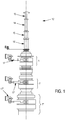
- the first and second arms 22 'and 22 "each comprise a jack 28.
- a jack can be integrated within such an arm or constitute the whole of the arm 22.
- a jack is a mechanical member allowing the creation of a translational movement along the axis of said member.
- a cylinder can also be considered as a linear actuator which transforms the energy of a pressurized fluid into mechanical energy.
- a cylinder is characterized by its stroke, that is to say the length of the movement to be ensured, by the diameter of its piston and by the pressure of the fluid, said diameter and said pressure depending on the force developed.
- a cylinder generally consists of a cylinder closed at both ends, defining one or more cavities. Inside said cavity, a movable part, in principle a piston 28p, is mounted on a first rigid rod 28t1, and makes it possible to separate the volume of the cavity into two chambers 28c1 and 28c2, isolated one from the other.
- the two rooms are preferably of the same section.
- the term "anterior chamber” 28c2 is used, the chamber not containing the first rod 28t1 of the jack and "posterior chamber” 28c1 the chamber containing the first rod 28t1 of the jack.
- the proximal part of the first rod 28t1 of the jack 28 thus cooperates with the surface of the piston 28p opening into the rear chamber 28c1, that is to say that said proximal part of the first rod 28t1 is fixed to said surface by any means .
- One or more openings 28o, in one or the other of the two chambers, ensure the introduction or the evacuation of the fluid and consequently the displacement of the piston.
- the first rod 28t1 guarantees the transmission of a force in the form of pressure and by way of consequence of a displacement.
- a jack 28 can advantageously have a damper (not shown in figures 3a to 3d ) in order to obtain a slowdown at the end of movement so as to avoid a shock of the piston on the bottom of the cavity inside the cylinder.
- a cylinder also includes seals for sealing at the piston 28p between the two chambers of the cavity and / or between the first rod and the body of the cylinder.
- the first rod 28t1 advantageously cooperates with the distal part 22p of the arm, while the end of the body of the jack, opposite to said first rod, advantageously cooperates with the proximal part 22p of the arm 22.
- first rod 28t1 can advantageously cooperate with the proximal part 22p of the arm, while the end of the cylinder body, opposite to said first rod, can advantageously cooperate with the distal part 22d of the arm. Said cooperation is done using any known attachment and / or attachment means allowing the materialization of a mechanical connection, by way of preferred but nonlimiting examples, pivot connections, ball joint or embedding.
- a jack 28 can also be characterized by its mode of action. Two types of action are distinguished in particular: single-acting cylinders, known under the name "VSE”, and double-acting cylinders, known under the name "VDE”. As illustrated in connection with the figure 3c , a cylinder 28 is said to have a single effect when the cylinder only works in one direction, that is to say that only one chamber is supplied with fluid, preferably the anterior chamber, and consequently, the arrival of the pressure is done only through a single opening 28o, driving the piston 28p in one direction. The return of the piston 28p is achieved under the action of a spring 28r, an equivalent system or an external force.
- a jack is said to have a double effect when the jack works in two directions, that is to say that the VDE jack has two possible feeds, by the anterior chamber 28c2 or by the posterior chamber 28c1: the pressurized fluid is thus sent on either side of the piston 28p depending on the desired work.
- a jack 28 has two openings 28o1 and 28o2 for supplying the device with fluid. Furthermore, pressure is applied alternately on each side of the piston 28p, said piston thus moving in one direction then in the other.
- the piston 28p moves to reduce the posterior chamber 28c1, said piston compressing or "driving out” the fluid from the posterior chamber 28c1.
- the piston 28p moves in the opposite direction, said piston 28p compressing or “driving out” the fluid from the anterior chamber 28c2.
- the effort in pushing that is to say when the first rod 28t1 leaves the cylinder cavity, is slightly greater than the force in pulling, that is to say that the first rod 28t1 penetrates the actuator cavity 28: in fact, the pressure does not act on the surface of the piston 28p occupied by the first rod 28t1 fixed to said surface, generally opening into the rear chamber 28c1 of the cavity.
- the pressure and the effort are therefore not identical in the two chambers anterior 28c2 and posterior 28c1 since the entry of material, represented by the entry of the first rod 28t1, is accomplished within the posterior chamber 28c1 only.
- double rod cylinders 28 are used.
- the principle of said double rod cylinders, illustrated in conjunction with the 3d figure is as follows: the first rod 28t1 enters and leaves the jack 28 within the rear chamber 28c1.
- the proximal part of a second rod 28t2 of the jack thus cooperates with the surface of the piston 28p opening into the anterior chamber 28c2, that is to say that said proximal part is fixed to said surface by any means.
- Said second rod 28t2 advantageously has a section substantially identical to the first rod, but can be of different length.
- first and second rods are advantageously parallel, but not necessarily mirrored to each other, that is to say that their respective points of attachment to the piston are not necessarily substantially identical.
- the longitudinal axes of the first and second rods 28t1 and 28t2 are coincident with the longitudinal axis of the arm with which the jack cooperates, that is to say that the first and second rods are in the extension of said arm.
- a drive system and / or guide 17 according to the invention comprises a double rod cylinder 28 in each arm 22.
- first and second arms 22 'and 22 "advantageously comprise first and second cylinders 28' and 28" respectively, advantageously with double rod and with double effect.
- Each cylinder has two openings, a 28o2 in the anterior chamber 28c2 and a 28o1 in the rear chamber 28c1, said openings alternately supplying and discharging the fluid within the anterior and posterior chambers.
- the first jack 28 ' has an opening 28o2 in its anterior chamber 28c2 and a 28o1 in its rear chamber 28c1, said rear chamber 28c1 allowing the insertion of the first rod 28t1 within it.
- the second cylinder 28 “has an opening 28o2 in its anterior chamber 28c2 and a 28o1 in its rear chamber 28c1, said rear chamber allowing the insertion of the first rod 28t1 therein.
- the opening 28o1 within the rear chamber 28c1 ensures the supply of pressurized fluid, while the opening 28o2 within the anterior chamber 28c2 guarantees the escape of the fluid.
- the opening 28o1 within the rear chamber 28c1 ensures the escape of the fluid, while the opening 28o2 within the anterior chamber 28c2 guarantees the supply in pressurized fluid.
- first and second conduits 27 'and 27" can be rigid or flexible and are made of a material capable of withstanding the pressure imposed by the fluid.
- the first and second conduits are rigid to avoid any swelling and / or any accumulation due to the pressure.
- a drive and / or guide system 17 for a rotary joint is in principle used within a fluid transfer system 12.
- a fluid transfer system generally comprises at least two modules of rotary joints, chosen from , by way of nonlimiting examples, rotary joints for fluid transfer, rotary optical and electrical connectors.
- At least one drive and / or guide system according to the invention is used within such a fluid transfer system. All or part, that is to say at least the ends, of the beam 23 of a drive and / or guide system 17 according to the invention advantageously cooperate with a gantry 30, also known under the name Anglo-Saxon " gantry structure ".
- Cooperation means any relevant fixation by any means.
- such a beam 23 can be directly integrated within said gantry 30.
- the mooring systems are in principle rotary and generally introduced within a floating production, storage and unloading unit, also known by the Anglo-Saxon name " Floating production storage and offloading ".
- Said units are generally in the form of a vessel cooperating with a drilling platform and at least one fluid transfer system, said system being able to be included within a mooring turret, a pivoting system allowing the vessel to s '' orient freely from so as to offer less resistance to sea currents.
- the floating unit includes a mooring system according to the invention.
- the invention has been described during its operation in relation to rotary joints for ensuring the transfer of fluids within floating unloading, production and storage units comprising a mooring turret. It can also be implemented for any type of rotary joints or any type of mobile platforms combined with an adequate mooring system.
- rotary joint can be applied to a rotary joint or to any other system more generally comprising a female member in rotation relative to a male member, said female member being subjected to the transmission of a couple.
- the invention could be implemented using any actuator capable of performing an action equivalent to that performed by the jack, for example a gear and rack assembly, the two elements being motorized.
Landscapes
- Engineering & Computer Science (AREA)
- Geology (AREA)
- Mechanical Engineering (AREA)
- Life Sciences & Earth Sciences (AREA)
- Mining & Mineral Resources (AREA)
- General Life Sciences & Earth Sciences (AREA)
- Fluid Mechanics (AREA)
- Environmental & Geological Engineering (AREA)
- Physics & Mathematics (AREA)
- Geochemistry & Mineralogy (AREA)
- Chemical & Material Sciences (AREA)
- Combustion & Propulsion (AREA)
- Ocean & Marine Engineering (AREA)
- Actuator (AREA)
- Manipulator (AREA)
Claims (11)
- System (17) für den Antrieb und/oder die Führung eines Drehgelenks (1), umfassend:- erste und zweite koplanare Arme (22', 22"), wobei die distalen Abschnitte (22d) des ersten und zweiten Arms (22', 22") durch Einhak- und/oder Befestigungsmittel (21) mit einem weiblichen Element (3) eines Drehgelenks (1) zusammenwirken;- einen Träger (23), der im Wesentlichen quer und koplanar ist und mit den proximalen Abschnitten (22'p; 22"p) des ersten und zweiten Arms (22', 22") zusammenwirkt,wobei das System dadurch gekennzeichnet ist, dass:- der erste und zweite Arm (22', 22") einen ersten und zweiten Doppelstangenzylinder (28', 28") umfassen;- der erste Zylinder (28') einen Kolben (28'p), eine hintere Kammer (28'c1) und eine vordere Kammer (28'c2) auf beiden Seiten des Kolbens (28'p) umfasst, wobei die Kammern den gleichen Querschnitt aufweisen;- der zweite Zylinder (28") einen Kolben (28"p), eine hintere Kammer (28"c1) und eine vordere Kammer (28"c2) auf jeder Seite des Kolbens (28p) umfasst, wobei die Kammern den gleichen Querschnitt wie die hintere (28'c1) und die vordere (28'c2) Kammer des ersten Zylinders (28') aufweisen;- die hintere Kammer (28'c1) des ersten Zylinders (28') über einen ersten Kanal (27') mit der vorderen Kammer (28"c2) des zweiten Zylinders (28") zusammenwirkt;- die hintere Kammer (28"c1) des zweiten Zylinders (28") über einen zweiten Kanal (27") mit der vorderen Kammer (28'c1) des ersten Zylinders (28') zusammenwirkt.
- Antriebs- und/oder Führungssystem (17) nach dem vorhergehenden Anspruch, wobei der erste und zweite Arm (22', 22") im wesentlichen parallel sind.
- Antriebs- und/oder Führungssystem (17) nach einem der vorhergehenden Ansprüche, wobei die ersten und zweiten Kanäle (27', 27") starr sind.
- Antriebs- und/oder Führungssystem (17) nach einem der vorhergehenden Ansprüche, wobei die proximalen Abschnitte (22'p, 22"p) der Arme (22', 22") mittels eines Kugelgelenks mit dem weiblichen Element (3) zusammenwirken.
- Antriebs- und/oder Führungssystem nach einem der Ansprüche 1 bis 3, wobei die proximalen Abschnitte (22'p, 22"p) der Arme (22', 22") mittels einer Schwenkverbindung mit dem weiblichen Element (3) zusammenwirken.
- Antriebs- und/oder Führungssystem nach einem der Ansprüche 1 bis 3, wobei die proximalen Abschnitte (22'p, 22"p) der Arme mittels einer Steckverbindung mit dem weiblichen Element (3) zusammenwirken.
- Antriebs- und/oder Führungssystem nach einem der vorhergehenden Ansprüche, wobei der erste und der zweite Zylinder (28', 28") pneumatisch sind.
- Antriebs- und/oder Führungssystem nach einem der Ansprüche 1 bis 6, wobei der erste und der zweite Zylinder (28', 28") hydraulisch sind.
- Fluidtransfersystem, umfassend ein Drehgelenk-Modul (1), wobei das Drehgelenk-Modul (1) mit einem Antriebs- und/oder Führungssystem (17) zusammenwirkt, wobei das Antriebs- und/oder Führungssystem (17) mit einer Schleuse (30) zusammenwirkt, wobei das Fluidtransfersystem dadurch gekennzeichnet ist, dass es mindestens ein Antriebs- und/oder Führungssystem (17) nach einem der Ansprüche 1 bis 8 umfasst.
- Verankerungssystem, umfassend einen Verankerungsturm, in dem ein Fluidtransfersystem angeordnet ist, dadurch gekennzeichnet, dass es ein Fluidtransfersystem nach Anspruch 9 umfasst.
- Schwimmende Entlade-, Produktions- und Lagereinheit, dadurch gekennzeichnet, dass sie ein Verankerungssystem nach Anspruch 10 umfasst.
Applications Claiming Priority (2)
| Application Number | Priority Date | Filing Date | Title |
|---|---|---|---|
| FR1454549A FR3021290B1 (fr) | 2014-05-20 | 2014-05-20 | Systeme d'entrainement et de guidage d'un joint tournant |
| PCT/FR2015/050564 WO2015177417A1 (fr) | 2014-05-20 | 2015-03-06 | Système d'entraînement et de guidage d'un joint tournant |
Publications (2)
| Publication Number | Publication Date |
|---|---|
| EP3152107A1 EP3152107A1 (de) | 2017-04-12 |
| EP3152107B1 true EP3152107B1 (de) | 2020-04-29 |
Family
ID=51210630
Family Applications (1)
| Application Number | Title | Priority Date | Filing Date |
|---|---|---|---|
| EP15714587.1A Not-in-force EP3152107B1 (de) | 2014-05-20 | 2015-03-06 | Antrieb und führungssystem eines drehgelenkes |
Country Status (3)
| Country | Link |
|---|---|
| EP (1) | EP3152107B1 (de) |
| FR (1) | FR3021290B1 (de) |
| WO (1) | WO2015177417A1 (de) |
Families Citing this family (1)
| Publication number | Priority date | Publication date | Assignee | Title |
|---|---|---|---|---|
| CN107630682A (zh) * | 2017-11-20 | 2018-01-26 | 孟凡星 | 一种海上石油开采平台 |
Family Cites Families (6)
| Publication number | Priority date | Publication date | Assignee | Title |
|---|---|---|---|---|
| NO885306L (no) * | 1988-11-28 | 1990-05-29 | Golar Nor Offshore As | System til overfoering av fluider fra et roeropplegg i et skipsskrog til en dreieinnretning og vice versa. |
| US5823837A (en) * | 1997-11-20 | 1998-10-20 | Fmc Corporation | Turret mooring system with product swivel stack |
| GB2336417B (en) * | 1998-03-13 | 2000-03-29 | Bluewater Terminal Systems Nv | Fluid transfer arrangement |
| CA2332996C (en) * | 1998-06-19 | 2004-08-17 | Fmc Corporation | Swivel torque tube arrangement |
| DE102011008145B3 (de) * | 2011-01-08 | 2012-02-02 | Parker Hannifin Gmbh | Energieeffizienter hydraulischer Antrieb für die Linearbewegung eines Massekörpers |
| DE102011005337A1 (de) * | 2011-03-10 | 2012-09-13 | Zf Friedrichshafen Ag | Antriebsanordnung zum Ausführen von Arbeitsbewegungen bei Arbeitsmaschinen |
-
2014
- 2014-05-20 FR FR1454549A patent/FR3021290B1/fr not_active Expired - Fee Related
-
2015
- 2015-03-06 EP EP15714587.1A patent/EP3152107B1/de not_active Not-in-force
- 2015-03-06 WO PCT/FR2015/050564 patent/WO2015177417A1/fr not_active Ceased
Non-Patent Citations (1)
| Title |
|---|
| None * |
Also Published As
| Publication number | Publication date |
|---|---|
| FR3021290B1 (fr) | 2016-05-27 |
| WO2015177417A1 (fr) | 2015-11-26 |
| EP3152107A1 (de) | 2017-04-12 |
| FR3021290A1 (fr) | 2015-11-27 |
Similar Documents
| Publication | Publication Date | Title |
|---|---|---|
| EP2928650B1 (de) | Sechsfüssiges system | |
| EP1148207B1 (de) | Verbindungsvorrichtung für eine Unterwasser-Flüssigkeitstransportleitung | |
| WO2014076080A1 (fr) | Bras articulé | |
| EP1228330B1 (de) | Greifersystem zum spannen einer rohrleitung, und seine schwimmfähige haltevorrichtung | |
| FR2941434A1 (fr) | Systeme de transfert d'un produit fluide et sa mise en oeuvre | |
| FR2484717A1 (fr) | Connecteur enfichable dans un milieu fluide | |
| WO2009101279A2 (fr) | Tronçon de colonne montante avec des conduites auxiliaires bridées et des connexions à baïonnette | |
| EP0296056A1 (de) | Element mit veränderlicher Steifheit für die Verwendung am Fuss einer Übergabeleitung | |
| EP3060464A1 (de) | Ankerkette | |
| EP3063059B1 (de) | System für den transfer von flüssigkeit zwischen einem schiff und einer einrichtung, wie einem kundenschiff | |
| EP2858887B1 (de) | Vorrichtung zum stoppen einer vertäuungskette sowie verfahren zur offshore-vertäuung einer schwimmfähigen struktur mit der darin eingebauten vorrichtung | |
| FR2858648A1 (fr) | Dispositif de liaison fond-surface comportant une articulation flexible etanche entre un riser et un flotteur | |
| FR2885613A1 (fr) | Dispositif de transfert de fluide entre deux supports flottants | |
| EP3152107B1 (de) | Antrieb und führungssystem eines drehgelenkes | |
| OA12510A (fr) | Dispositif de liaison fond-surface comportant une conduite sous-marine assemblée à au moins un flotteur. | |
| FR3018063A1 (fr) | Stoppeur de chaine pour unite flottante et systeme d'ancrage pour unite flottante associe | |
| EP3102864B1 (de) | Drehgelenk mit druckdichtungsringen | |
| FR2676598A1 (fr) | Liaison hyperfrequence mobile a guide d'ondes. | |
| WO2013030486A1 (fr) | Vérin d'actionnement | |
| WO2012045925A1 (fr) | Dispositif de manoeuvre des robinets d'un connecteur-deconnecteur | |
| FR3069520A1 (fr) | Dispositif de liaison amortie pour navire | |
| WO1997047856A2 (fr) | Systeme et procede de liaison entre deux ensembles mobiles l'un par rapport a l'autre, notamment dans des installations sous-marines | |
| EP3680510A1 (de) | Hydroelastischer dämpfer, rotor mit einem solchen hydroelastischen dämpfer und zugehöriges flugzeug | |
| OA17101A (en) | Installation de liaisons fond-surface de type tour hybride multi-risers comprenant des conduites flexibles à flottabilité positive. | |
| FR2715188A1 (fr) | Vanne de sécurité pour puits d'accès à des réservoirs souterrains de fluides sous pression et son utilisation. |
Legal Events
| Date | Code | Title | Description |
|---|---|---|---|
| STAA | Information on the status of an ep patent application or granted ep patent |
Free format text: STATUS: THE INTERNATIONAL PUBLICATION HAS BEEN MADE |
|
| PUAI | Public reference made under article 153(3) epc to a published international application that has entered the european phase |
Free format text: ORIGINAL CODE: 0009012 |
|
| STAA | Information on the status of an ep patent application or granted ep patent |
Free format text: STATUS: REQUEST FOR EXAMINATION WAS MADE |
|
| 17P | Request for examination filed |
Effective date: 20161125 |
|
| AK | Designated contracting states |
Kind code of ref document: A1 Designated state(s): AL AT BE BG CH CY CZ DE DK EE ES FI FR GB GR HR HU IE IS IT LI LT LU LV MC MK MT NL NO PL PT RO RS SE SI SK SM TR |
|
| AX | Request for extension of the european patent |
Extension state: BA ME |
|
| DAV | Request for validation of the european patent (deleted) | ||
| DAX | Request for extension of the european patent (deleted) | ||
| GRAP | Despatch of communication of intention to grant a patent |
Free format text: ORIGINAL CODE: EPIDOSNIGR1 |
|
| STAA | Information on the status of an ep patent application or granted ep patent |
Free format text: STATUS: GRANT OF PATENT IS INTENDED |
|
| INTG | Intention to grant announced |
Effective date: 20191125 |
|
| GRAS | Grant fee paid |
Free format text: ORIGINAL CODE: EPIDOSNIGR3 |
|
| GRAA | (expected) grant |
Free format text: ORIGINAL CODE: 0009210 |
|
| STAA | Information on the status of an ep patent application or granted ep patent |
Free format text: STATUS: THE PATENT HAS BEEN GRANTED |
|
| RAP1 | Party data changed (applicant data changed or rights of an application transferred) |
Owner name: O.S.C OFFSHORE SYSTEMS CONCEPTS |
|
| AK | Designated contracting states |
Kind code of ref document: B1 Designated state(s): AL AT BE BG CH CY CZ DE DK EE ES FI FR GB GR HR HU IE IS IT LI LT LU LV MC MK MT NL NO PL PT RO RS SE SI SK SM TR |
|
| REG | Reference to a national code |
Ref country code: GB Ref legal event code: FG4D Free format text: NOT ENGLISH |
|
| REG | Reference to a national code |
Ref country code: CH Ref legal event code: EP |
|
| REG | Reference to a national code |
Ref country code: DE Ref legal event code: R096 Ref document number: 602015051593 Country of ref document: DE |
|
| REG | Reference to a national code |
Ref country code: AT Ref legal event code: REF Ref document number: 1262918 Country of ref document: AT Kind code of ref document: T Effective date: 20200515 |
|
| REG | Reference to a national code |
Ref country code: IE Ref legal event code: FG4D Free format text: LANGUAGE OF EP DOCUMENT: FRENCH |
|
| REG | Reference to a national code |
Ref country code: NL Ref legal event code: MP Effective date: 20200429 |
|
| REG | Reference to a national code |
Ref country code: LT Ref legal event code: MG4D |
|
| PG25 | Lapsed in a contracting state [announced via postgrant information from national office to epo] |
Ref country code: SE Free format text: LAPSE BECAUSE OF FAILURE TO SUBMIT A TRANSLATION OF THE DESCRIPTION OR TO PAY THE FEE WITHIN THE PRESCRIBED TIME-LIMIT Effective date: 20200429 Ref country code: PT Free format text: LAPSE BECAUSE OF FAILURE TO SUBMIT A TRANSLATION OF THE DESCRIPTION OR TO PAY THE FEE WITHIN THE PRESCRIBED TIME-LIMIT Effective date: 20200831 Ref country code: LT Free format text: LAPSE BECAUSE OF FAILURE TO SUBMIT A TRANSLATION OF THE DESCRIPTION OR TO PAY THE FEE WITHIN THE PRESCRIBED TIME-LIMIT Effective date: 20200429 Ref country code: FI Free format text: LAPSE BECAUSE OF FAILURE TO SUBMIT A TRANSLATION OF THE DESCRIPTION OR TO PAY THE FEE WITHIN THE PRESCRIBED TIME-LIMIT Effective date: 20200429 Ref country code: IS Free format text: LAPSE BECAUSE OF FAILURE TO SUBMIT A TRANSLATION OF THE DESCRIPTION OR TO PAY THE FEE WITHIN THE PRESCRIBED TIME-LIMIT Effective date: 20200829 Ref country code: NO Free format text: LAPSE BECAUSE OF FAILURE TO SUBMIT A TRANSLATION OF THE DESCRIPTION OR TO PAY THE FEE WITHIN THE PRESCRIBED TIME-LIMIT Effective date: 20200729 Ref country code: GR Free format text: LAPSE BECAUSE OF FAILURE TO SUBMIT A TRANSLATION OF THE DESCRIPTION OR TO PAY THE FEE WITHIN THE PRESCRIBED TIME-LIMIT Effective date: 20200730 |
|
| REG | Reference to a national code |
Ref country code: AT Ref legal event code: MK05 Ref document number: 1262918 Country of ref document: AT Kind code of ref document: T Effective date: 20200429 |
|
| PG25 | Lapsed in a contracting state [announced via postgrant information from national office to epo] |
Ref country code: LV Free format text: LAPSE BECAUSE OF FAILURE TO SUBMIT A TRANSLATION OF THE DESCRIPTION OR TO PAY THE FEE WITHIN THE PRESCRIBED TIME-LIMIT Effective date: 20200429 Ref country code: HR Free format text: LAPSE BECAUSE OF FAILURE TO SUBMIT A TRANSLATION OF THE DESCRIPTION OR TO PAY THE FEE WITHIN THE PRESCRIBED TIME-LIMIT Effective date: 20200429 Ref country code: BG Free format text: LAPSE BECAUSE OF FAILURE TO SUBMIT A TRANSLATION OF THE DESCRIPTION OR TO PAY THE FEE WITHIN THE PRESCRIBED TIME-LIMIT Effective date: 20200729 Ref country code: RS Free format text: LAPSE BECAUSE OF FAILURE TO SUBMIT A TRANSLATION OF THE DESCRIPTION OR TO PAY THE FEE WITHIN THE PRESCRIBED TIME-LIMIT Effective date: 20200429 |
|
| PG25 | Lapsed in a contracting state [announced via postgrant information from national office to epo] |
Ref country code: NL Free format text: LAPSE BECAUSE OF FAILURE TO SUBMIT A TRANSLATION OF THE DESCRIPTION OR TO PAY THE FEE WITHIN THE PRESCRIBED TIME-LIMIT Effective date: 20200429 Ref country code: AL Free format text: LAPSE BECAUSE OF FAILURE TO SUBMIT A TRANSLATION OF THE DESCRIPTION OR TO PAY THE FEE WITHIN THE PRESCRIBED TIME-LIMIT Effective date: 20200429 |
|
| PG25 | Lapsed in a contracting state [announced via postgrant information from national office to epo] |
Ref country code: CZ Free format text: LAPSE BECAUSE OF FAILURE TO SUBMIT A TRANSLATION OF THE DESCRIPTION OR TO PAY THE FEE WITHIN THE PRESCRIBED TIME-LIMIT Effective date: 20200429 Ref country code: RO Free format text: LAPSE BECAUSE OF FAILURE TO SUBMIT A TRANSLATION OF THE DESCRIPTION OR TO PAY THE FEE WITHIN THE PRESCRIBED TIME-LIMIT Effective date: 20200429 Ref country code: ES Free format text: LAPSE BECAUSE OF FAILURE TO SUBMIT A TRANSLATION OF THE DESCRIPTION OR TO PAY THE FEE WITHIN THE PRESCRIBED TIME-LIMIT Effective date: 20200429 Ref country code: EE Free format text: LAPSE BECAUSE OF FAILURE TO SUBMIT A TRANSLATION OF THE DESCRIPTION OR TO PAY THE FEE WITHIN THE PRESCRIBED TIME-LIMIT Effective date: 20200429 Ref country code: IT Free format text: LAPSE BECAUSE OF FAILURE TO SUBMIT A TRANSLATION OF THE DESCRIPTION OR TO PAY THE FEE WITHIN THE PRESCRIBED TIME-LIMIT Effective date: 20200429 Ref country code: SM Free format text: LAPSE BECAUSE OF FAILURE TO SUBMIT A TRANSLATION OF THE DESCRIPTION OR TO PAY THE FEE WITHIN THE PRESCRIBED TIME-LIMIT Effective date: 20200429 Ref country code: AT Free format text: LAPSE BECAUSE OF FAILURE TO SUBMIT A TRANSLATION OF THE DESCRIPTION OR TO PAY THE FEE WITHIN THE PRESCRIBED TIME-LIMIT Effective date: 20200429 Ref country code: DK Free format text: LAPSE BECAUSE OF FAILURE TO SUBMIT A TRANSLATION OF THE DESCRIPTION OR TO PAY THE FEE WITHIN THE PRESCRIBED TIME-LIMIT Effective date: 20200429 |
|
| REG | Reference to a national code |
Ref country code: DE Ref legal event code: R097 Ref document number: 602015051593 Country of ref document: DE |
|
| PG25 | Lapsed in a contracting state [announced via postgrant information from national office to epo] |
Ref country code: SK Free format text: LAPSE BECAUSE OF FAILURE TO SUBMIT A TRANSLATION OF THE DESCRIPTION OR TO PAY THE FEE WITHIN THE PRESCRIBED TIME-LIMIT Effective date: 20200429 Ref country code: PL Free format text: LAPSE BECAUSE OF FAILURE TO SUBMIT A TRANSLATION OF THE DESCRIPTION OR TO PAY THE FEE WITHIN THE PRESCRIBED TIME-LIMIT Effective date: 20200429 |
|
| PLBE | No opposition filed within time limit |
Free format text: ORIGINAL CODE: 0009261 |
|
| STAA | Information on the status of an ep patent application or granted ep patent |
Free format text: STATUS: NO OPPOSITION FILED WITHIN TIME LIMIT |
|
| 26N | No opposition filed |
Effective date: 20210201 |
|
| PG25 | Lapsed in a contracting state [announced via postgrant information from national office to epo] |
Ref country code: SI Free format text: LAPSE BECAUSE OF FAILURE TO SUBMIT A TRANSLATION OF THE DESCRIPTION OR TO PAY THE FEE WITHIN THE PRESCRIBED TIME-LIMIT Effective date: 20200429 |
|
| REG | Reference to a national code |
Ref country code: DE Ref legal event code: R119 Ref document number: 602015051593 Country of ref document: DE |
|
| PG25 | Lapsed in a contracting state [announced via postgrant information from national office to epo] |
Ref country code: MC Free format text: LAPSE BECAUSE OF FAILURE TO SUBMIT A TRANSLATION OF THE DESCRIPTION OR TO PAY THE FEE WITHIN THE PRESCRIBED TIME-LIMIT Effective date: 20200429 |
|
| REG | Reference to a national code |
Ref country code: CH Ref legal event code: PL |
|
| GBPC | Gb: european patent ceased through non-payment of renewal fee |
Effective date: 20210306 |
|
| REG | Reference to a national code |
Ref country code: BE Ref legal event code: MM Effective date: 20210331 |
|
| PG25 | Lapsed in a contracting state [announced via postgrant information from national office to epo] |
Ref country code: DE Free format text: LAPSE BECAUSE OF NON-PAYMENT OF DUE FEES Effective date: 20211001 Ref country code: GB Free format text: LAPSE BECAUSE OF NON-PAYMENT OF DUE FEES Effective date: 20210306 Ref country code: FR Free format text: LAPSE BECAUSE OF NON-PAYMENT OF DUE FEES Effective date: 20210331 Ref country code: IE Free format text: LAPSE BECAUSE OF NON-PAYMENT OF DUE FEES Effective date: 20210306 Ref country code: LU Free format text: LAPSE BECAUSE OF NON-PAYMENT OF DUE FEES Effective date: 20210306 Ref country code: LI Free format text: LAPSE BECAUSE OF NON-PAYMENT OF DUE FEES Effective date: 20210331 Ref country code: CH Free format text: LAPSE BECAUSE OF NON-PAYMENT OF DUE FEES Effective date: 20210331 |
|
| PG25 | Lapsed in a contracting state [announced via postgrant information from national office to epo] |
Ref country code: BE Free format text: LAPSE BECAUSE OF NON-PAYMENT OF DUE FEES Effective date: 20210331 |
|
| PG25 | Lapsed in a contracting state [announced via postgrant information from national office to epo] |
Ref country code: HU Free format text: LAPSE BECAUSE OF FAILURE TO SUBMIT A TRANSLATION OF THE DESCRIPTION OR TO PAY THE FEE WITHIN THE PRESCRIBED TIME-LIMIT; INVALID AB INITIO Effective date: 20150306 |
|
| PG25 | Lapsed in a contracting state [announced via postgrant information from national office to epo] |
Ref country code: CY Free format text: LAPSE BECAUSE OF FAILURE TO SUBMIT A TRANSLATION OF THE DESCRIPTION OR TO PAY THE FEE WITHIN THE PRESCRIBED TIME-LIMIT Effective date: 20200429 |
|
| PG25 | Lapsed in a contracting state [announced via postgrant information from national office to epo] |
Ref country code: MK Free format text: LAPSE BECAUSE OF FAILURE TO SUBMIT A TRANSLATION OF THE DESCRIPTION OR TO PAY THE FEE WITHIN THE PRESCRIBED TIME-LIMIT Effective date: 20200429 |
|
| PG25 | Lapsed in a contracting state [announced via postgrant information from national office to epo] |
Ref country code: TR Free format text: LAPSE BECAUSE OF FAILURE TO SUBMIT A TRANSLATION OF THE DESCRIPTION OR TO PAY THE FEE WITHIN THE PRESCRIBED TIME-LIMIT Effective date: 20200429 |
|
| PG25 | Lapsed in a contracting state [announced via postgrant information from national office to epo] |
Ref country code: MT Free format text: LAPSE BECAUSE OF FAILURE TO SUBMIT A TRANSLATION OF THE DESCRIPTION OR TO PAY THE FEE WITHIN THE PRESCRIBED TIME-LIMIT Effective date: 20200429 |