EP3152178B1 - Verfahren zur expansion von sandkornförmigem rohmaterial - Google Patents
Verfahren zur expansion von sandkornförmigem rohmaterial Download PDFInfo
- Publication number
- EP3152178B1 EP3152178B1 EP15738815.8A EP15738815A EP3152178B1 EP 3152178 B1 EP3152178 B1 EP 3152178B1 EP 15738815 A EP15738815 A EP 15738815A EP 3152178 B1 EP3152178 B1 EP 3152178B1
- Authority
- EP
- European Patent Office
- Prior art keywords
- shaft
- conveying
- flow
- section
- granulate
- Prior art date
- Legal status (The legal status is an assumption and is not a legal conclusion. Google has not performed a legal analysis and makes no representation as to the accuracy of the status listed.)
- Not-in-force
Links
- 238000000034 method Methods 0.000 title claims description 49
- 239000002994 raw material Substances 0.000 title claims description 24
- 239000004576 sand Substances 0.000 title claims description 17
- 239000000463 material Substances 0.000 claims description 87
- 239000008187 granular material Substances 0.000 claims description 67
- 238000009825 accumulation Methods 0.000 claims description 39
- 238000010438 heat treatment Methods 0.000 claims description 13
- 230000001105 regulatory effect Effects 0.000 claims description 11
- 238000000605 extraction Methods 0.000 claims description 6
- 229910052500 inorganic mineral Inorganic materials 0.000 description 23
- 239000011707 mineral Substances 0.000 description 23
- 235000010755 mineral Nutrition 0.000 description 23
- 239000011230 binding agent Substances 0.000 description 11
- 239000000428 dust Substances 0.000 description 10
- 239000007789 gas Substances 0.000 description 10
- 239000004604 Blowing Agent Substances 0.000 description 8
- 239000003570 air Substances 0.000 description 8
- 230000033228 biological regulation Effects 0.000 description 6
- 230000000694 effects Effects 0.000 description 6
- 239000003380 propellant Substances 0.000 description 6
- XLYOFNOQVPJJNP-UHFFFAOYSA-N water Substances O XLYOFNOQVPJJNP-UHFFFAOYSA-N 0.000 description 6
- 239000012080 ambient air Substances 0.000 description 5
- 230000015572 biosynthetic process Effects 0.000 description 5
- 230000001276 controlling effect Effects 0.000 description 5
- 238000013461 design Methods 0.000 description 4
- 239000004033 plastic Substances 0.000 description 4
- 230000008092 positive effect Effects 0.000 description 4
- 230000008961 swelling Effects 0.000 description 4
- 238000004519 manufacturing process Methods 0.000 description 3
- 238000005303 weighing Methods 0.000 description 3
- VTYYLEPIZMXCLO-UHFFFAOYSA-L Calcium carbonate Chemical compound [Ca+2].[O-]C([O-])=O VTYYLEPIZMXCLO-UHFFFAOYSA-L 0.000 description 2
- 238000010276 construction Methods 0.000 description 2
- 230000007423 decrease Effects 0.000 description 2
- 238000002347 injection Methods 0.000 description 2
- 239000007924 injection Substances 0.000 description 2
- 238000012423 maintenance Methods 0.000 description 2
- 238000007789 sealing Methods 0.000 description 2
- 230000005540 biological transmission Effects 0.000 description 1
- 229910000019 calcium carbonate Inorganic materials 0.000 description 1
- 235000010216 calcium carbonate Nutrition 0.000 description 1
- 239000007795 chemical reaction product Substances 0.000 description 1
- 238000004140 cleaning Methods 0.000 description 1
- 230000003247 decreasing effect Effects 0.000 description 1
- 238000001514 detection method Methods 0.000 description 1
- 238000005516 engineering process Methods 0.000 description 1
- 239000011159 matrix material Substances 0.000 description 1
- 238000005259 measurement Methods 0.000 description 1
- 239000002184 metal Substances 0.000 description 1
- 239000000203 mixture Substances 0.000 description 1
- 239000005332 obsidian Substances 0.000 description 1
- 239000002245 particle Substances 0.000 description 1
- 239000010451 perlite Substances 0.000 description 1
- 235000019362 perlite Nutrition 0.000 description 1
- 238000007639 printing Methods 0.000 description 1
- 238000012545 processing Methods 0.000 description 1
- 230000005855 radiation Effects 0.000 description 1
Images

Classifications
-
- C—CHEMISTRY; METALLURGY
- C04—CEMENTS; CONCRETE; ARTIFICIAL STONE; CERAMICS; REFRACTORIES
- C04B—LIME, MAGNESIA; SLAG; CEMENTS; COMPOSITIONS THEREOF, e.g. MORTARS, CONCRETE OR LIKE BUILDING MATERIALS; ARTIFICIAL STONE; CERAMICS; REFRACTORIES; TREATMENT OF NATURAL STONE
- C04B20/00—Use of materials as fillers for mortars, concrete or artificial stone according to more than one of groups C04B14/00 - C04B18/00 and characterised by shape or grain distribution; Treatment of materials according to more than one of the groups C04B14/00 - C04B18/00 specially adapted to enhance their filling properties in mortars, concrete or artificial stone; Expanding or defibrillating materials
- C04B20/02—Treatment
- C04B20/04—Heat treatment
- C04B20/06—Expanding clay, perlite, vermiculite or like granular materials
- C04B20/068—Selection of ingredients added before or during the thermal treatment, e.g. expansion promoting agents or particle-coating materials
-
- B—PERFORMING OPERATIONS; TRANSPORTING
- B65—CONVEYING; PACKING; STORING; HANDLING THIN OR FILAMENTARY MATERIAL
- B65G—TRANSPORT OR STORAGE DEVICES, e.g. CONVEYORS FOR LOADING OR TIPPING, SHOP CONVEYOR SYSTEMS OR PNEUMATIC TUBE CONVEYORS
- B65G53/00—Conveying materials in bulk through troughs, pipes or tubes by floating the materials or by flow of gas, liquid or foam
- B65G53/34—Details
- B65G53/58—Devices for accelerating or decelerating flow of the materials; Use of pressure generators
-
- C—CHEMISTRY; METALLURGY
- C04—CEMENTS; CONCRETE; ARTIFICIAL STONE; CERAMICS; REFRACTORIES
- C04B—LIME, MAGNESIA; SLAG; CEMENTS; COMPOSITIONS THEREOF, e.g. MORTARS, CONCRETE OR LIKE BUILDING MATERIALS; ARTIFICIAL STONE; CERAMICS; REFRACTORIES; TREATMENT OF NATURAL STONE
- C04B20/00—Use of materials as fillers for mortars, concrete or artificial stone according to more than one of groups C04B14/00 - C04B18/00 and characterised by shape or grain distribution; Treatment of materials according to more than one of the groups C04B14/00 - C04B18/00 specially adapted to enhance their filling properties in mortars, concrete or artificial stone; Expanding or defibrillating materials
- C04B20/02—Treatment
- C04B20/04—Heat treatment
- C04B20/06—Expanding clay, perlite, vermiculite or like granular materials
- C04B20/066—Expanding clay, perlite, vermiculite or like granular materials in shaft or vertical furnaces
-
- F—MECHANICAL ENGINEERING; LIGHTING; HEATING; WEAPONS; BLASTING
- F27—FURNACES; KILNS; OVENS; RETORTS
- F27B—FURNACES, KILNS, OVENS OR RETORTS IN GENERAL; OPEN SINTERING OR LIKE APPARATUS
- F27B1/00—Shaft or like vertical or substantially vertical furnaces
- F27B1/10—Details, accessories or equipment specially adapted for furnaces of these types
- F27B1/21—Arrangements of devices for discharging
Definitions
- the invention relates to a process for the expansion of sand grain raw material, in which the raw material by a means provided for heating, substantially vertical heated shaft in which a shaft flow prevails, falls down, as well as to a metering element, which with a essentially vertical shaft and a conveyor line is connectable.
- a method for producing a blown granules of sand grain raw material is in WO 2013/053635 A1 whose object is to controllably adjust a closed surface of the expanded granules so that the expanded granules have little or no hygroscopicity.
- the possibility should be created to specifically influence the surface structure of the expanded granules and thus the roughness.
- this document proposes to provide a plurality of heating elements arranged independently of one another along the drop section of the sand grain-shaped raw material and to carry out temperature detection along the drop zone, the heating elements being controlled below the region in which the expansion process takes place as a function of the detected temperature.
- the removal of the expanded granules from the lower end of the drop section is ensured by a pneumatic conveying line into which the drop section opens.
- a disadvantage of the prior art is thus the uneven swelling process and the formation of caking on the shaft walls, which are due to crossflows caused by e.g. Pressure fluctuations in the subsequent pneumatic conveying line, occur. Also, the known extraction / injection of process gases from / into the head area of the shaft can not prevent this effect.
- the problem underlying the present invention is to provide a method for producing a blown granules of sandkornförmigem raw material and a metering element for connecting the shaft to the delivery line, which do not have the disadvantages described and ensure that pressure fluctuations from the delivery line not on the Quality of the expanded granules.
- the process should ensure trouble-free and maintenance-free operation.
- the Dosing is to be characterized by a simple and reliable construction.
- the invention should be retrofittable to existing systems without much effort.
- a metering element is mounted, in which the amount of granules which passes from the shaft into the delivery line is controlled by means of regulation, so that a defined material accumulation of the granules is formed in the metering element as a buffer, which decouples the shaft flow of the delivery flow.
- the invention is based on that can be adjusted by a collection of material that can be formed by simple means, such as by damming the falling granules, in the range above the material pressure conditions that are no longer affected by the pressure fluctuations in the delivery line in normal operation. It goes without saying that the formation of a material accumulation complete gas-tight sealing of the shaft with respect to the conveying line can not be achieved, however, the sealing effect is sufficient to prevent transmission of pressure fluctuations of the delivery flow to the shaft flow.
- the amount of material accumulation can be specifically influenced and adjusted to the optimum value for the current process, with lower limits and upper limits must not be exceeded.
- the sand grain raw material not only mineral sands in which water is bound as a blowing agent such as perlite or obsidian sand can be used.
- it may be mineral dust mixed with hydrous mineral binder, in which case the hydrous mineral binder acts as a propellant.
- the swelling process can take place as follows:
- the mineral dust which consists of relatively small grains of sand For example, 20 pm diameter, forms with the binder larger grains, for example, 500 pm.
- the surfaces of the grains of sand of the mineral dust become plastic and form closed surfaces of the larger grains or melt into them.
- the closed surface of a single larger grain is generally smaller overall than the sum of all surfaces of the individual grains of sand of the mineral dust, which are involved in the formation of this larger grain, in this way surface energy is gained or increases the ratio of surface Volume off.
- the hydrous mineral binder is used as a blowing agent.
- mineral dust can be mixed with a blowing agent, wherein the blowing agent is mixed with mineral binder, which preferably contains water.
- blowing agent for example CaCO3
- the swelling process can proceed analogously to the one described above: the mineral dust, which has a relatively small grain size (for example 20 ⁇ m diameter), forms larger grains (for example 500 ⁇ m diameter) with the blowing agent and the mineral binder.
- the surfaces of the sand grains of the mineral dust Upon reaching a critical temperature, the surfaces of the sand grains of the mineral dust become plastic and form a closed surface of the larger grains or merge into one.
- the closed surfaces of the larger grains are still plastic and can now be blown by the propellant. If the mineral binder is hydrous, it may act as an additional propellant.
- the mineral binder preferably contains water and acts as an additional blowing agent.
- inventive method can, for example, as in the WO 2013/053635 A1 be educated. Their disclosure is therefore fully incorporated into this description.
- a preferred embodiment is characterized in that the material accumulation, which serves as a buffer, is designed such that at least a first cross section of the metering element is completely filled with blown granules from the shaft over a defined height.
- This type of buffer is characterized by the fact that it is particularly easy to manufacture. In the process, the expanded granules falling out of the shaft are dammed until a certain height has been reached, and the resulting accumulation of material serves as a buffer.
- the height of the accumulation of material can be defined, for example, by the location of a measuring device which is mounted in the metering element and detects the presence of material accumulation. The location of the measuring device corresponds in the operating state of the metering device of a certain height within the metering device and thus also a certain amount of material then existing collection.
- the delivery flow is generated by a suction device. If the extraction system is mounted in particular on the end facing away from the dosing, results in a flow over the entire length of the delivery line, whereby other elements, such as filter systems, may be mounted in the delivery line.
- a separating device preferably a gas cyclone, is provided in the conveying line, through which the expanded granules are separated from the conveying flow. Since the expanded granulate is the end product of the process, the bundled discharge from the delivery flow, in particular by a gas cyclone, is advantageous, since in this way a container, such as a silo, for further transport or further processing of the granules , can be filled in a simple way.
- a further preferred embodiment provides that the bulk density of the granules is determined as a quality feature of the expansion process in order to regulate the means for heating or to reduce the abandonment of raw material.
- Such a procedure makes it possible to draw conclusions about the conditions in the shaft through continuous control of the expanded granules. If the bulk density deviates significantly from the set standard parameters, then this may be due to a different composition of the sand grain raw material on the one hand, which can be compensated by changing the temperature in the means for heating, or on caking on the insides of the shaft. If the latter case occurs, the task of raw material can be reduced, preferably completely stopped, in order to carry out maintenance work.
- the means for regulating via a local influencing of the delivery flow in the dosing element increases or decreases the delivery rate of the expanded granules in the delivery line.
- Such control of the flow rate can do without moving parts, which come into contact with the expanded granules and is thus resistant to clogging.
- a reduction in the flow rate leads to an increase in the accumulation of material, while with an increase in the flow rate the opposite occurs.
- the height of the material accumulation in the metering element is detected and this Information transmitted to the means of regulation.
- the height of the material accumulation can be varied by influencing the flow rate or an uneven task of raw material can be compensated, so that the height of the material accumulation remains approximately constant.
- process air is sucked out of the head region of the shaft in order to increase the part of the shaft flow directed toward the head region and thus to stabilize it.
- a further preferred embodiment variant of the invention provides that process air is injected or sucked into the head region of the shaft in order to stabilize the part of the shaft flow directed towards the head region. This represents a further possibility to keep the flow conditions in the shaft approximately constant and has a positive effect on the quality of the expanded granules due to the simultaneous reduction of the pressure fluctuations originating from the delivery line.
- the dosing element according to the invention is characterized in that it comprises a material container, which can be connected to the shaft via a shaft connection and has a longitudinal axis, a conveying section, which can be connected to the conveying line via a delivery connection, and means for regulation, which are designed that in the area of the material container a collection of material is produced when granules enter the material container.
- the metering element can be connected to the shaft so that blown granules get into the material container.
- About the conveyor section passes the granules to the delivery port through which the dosing can be connected to the feed line to the removal of the arrived through the dosing element expanded To ensure granules.
- the means for controlling the flow rate, which passes through the metering element influenced in such a way that forms a material accumulation in the material container by more granules from the shaft falls into the material container, as is discharged via the delivery port from the metering. If the accumulation of material has reached a certain defined height, the delivery rate through the metering element will approximately correspond to the amount of granulate falling from the shaft into the material container.
- a system according to the invention can be designed such that the essentially vertical, heated shaft is connected via the shaft connection to the material container of the metering element in which there are means for regulating the delivery rate, and the delivery section of the metering element is connected to the pneumatic delivery line via the delivery connection is.
- the invention also relates to a system for carrying out a method according to the invention with a metering element which is connected to a substantially vertical heatable shaft and a pneumatic conveying line, wherein according to the invention it is provided that the metering element a material container, which is connected via a shaft connection to the shaft and a longitudinal axis, a conveying portion which is connected via a delivery port to the delivery line, and means for regulating, which are formed so that in the region of the material container, a material accumulation is produced when granules enter the material container.
- the conveying section is guided transversely to the longitudinal axis of the shaft through the material container.
- This way of connecting conveyor section and material container is characterized by the fact that no complicated construction is necessary.
- the material container For example, can be welded together from sheet metal plates and only needs to be dimensioned so that its dimensions are greater than the diameter of the conveyor section.
- the conveying section can be connected to the surrounding atmosphere on the side opposite the delivery connection, whereby the extraction system can suck in ambient air and transport it through the delivery line to produce the delivery flow.
- the conveying section has at least one opening on the side opposite the shaft connection in order to ensure the passage of expanded granules into the conveying section.
- Another particularly preferred embodiment of the metering element according to the invention or a system according to the invention provides that in the region of the material container, a measuring device is mounted, with which the amount of material accumulation can be detected and which is coupled to the means for controlling the flow rate. Thereby, the flow rate, depending on the amount of material accumulation on the means for control can be increased or decreased. If the pump falls below a minimum level, the flow rate is throttled, if a maximum height is exceeded, the flow rate is increased.
- the means for controlling the flow rate as an inner tube, which is arranged within the conveying section, with a is located therein control flap is executed. Due to this simple design of the means for controlling a regulation of the flow rate on the adjustment of the flap is possible.
- the inner tube is preferably the same length as the conveyor section and connected in the operating state on the same side as the conveyor section with the atmosphere, so that ambient air can be sucked through the inner tube.
- control flap is designed such that it is on the one hand closable and thus reduces the flow-through cross-section of the inner tube, when exceeding a defined amount of material accumulation is detected by the measuring device to to increase the flow rate and thus reduce the amount of material accumulation, and on the other hand openable and thus increases the flow-through cross-section of the inner tube when a drop below a defined level of material accumulation is detected by the measuring device to reduce the flow rate and thus the height to increase the material accumulation. Because the control flap has the same diameter as the inner tube, a flow-through cross section can be adjusted.
- control flap is normal to the longitudinal axis of the inner tube, there is no cross section flowed through and there is a strong suction in the region between the inner tube and the inner surface of the conveyor section, whereby more puffed granules from the material container is sucked. If the control flap is parallel to the longitudinal axis of the inner tube, the same suction effect prevails over the entire cross section of the conveying section and only a small amount of granules reaches the conveying section.
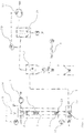
- FIG. 1 shows a plant for expansion of sand grain-shaped raw material 1.
- the raw material 1 falls through a vertical shaft 3, which with means 2 for heating, in the present embodiment, a plurality of electrical resistance heaters 2 is used, is heated.
- the task of the raw material takes place in the head region 16 of the shaft 3.
- a specific temperature profile can be set along the shaft 3. Due to the heat radiation, which acts on the raw material 1 from the shaft 3, the raw material 1 expands into blown granules 5.
- a shaft flow 4 sets in, which results from a boundary layer flow close to the wall in the direction of the head region 16 and a central core flow in the direction of the shaft connection 20.
- a further suction device 17 is provided which sucks process air 18 from the head region 16 and thus improves the shaft flow 4.
- a control loop 30 is coupled to the further suction device 17, which regulates the proportion of extracted process air 18 and the intake of ambient air.
- process air 18 are blown into the head area 16, either by this further suction device 17 or by another, not shown here device.
- a metering element 6 which determines the amount of granules 5, which from the shaft 3 in the pneumatic conveying line 7 is promoted _regelt.
- the metering element 6 has a shaft connection 20 at the connection point with the shaft 3 and a delivery connection 23 at the connection point to the delivery line 7. Also, in the part of the metering element 6 which adjoins the shaft 3, a measuring device 15 is attached via which Measured data, the flow rate is regulated.
- a suction device 12 is mounted, which is preferably designed as a fan, the ambient air from the other end, which is open to the environment, the feed line 7 sucks through this and so conveys blown granules 5.
- a gas cyclone 13 is arranged, via which the granules 5 is separated from the feed line.
- a filter system 28 which is preferably arranged between the gas cyclone 13 and suction device 12, which separates small particles from the delivery line 7.
- the Fig. 1 shows that in this embodiment, a weighing device 14, which, based on the flow of the granules 5, is arranged after the gas cyclone 13, is provided, with which the weight and thus the bulk density of the deposited expanded granules 5 can be determined.
- a weighing device 14 which, based on the flow of the granules 5, is arranged after the gas cyclone 13, is provided, with which the weight and thus the bulk density of the deposited expanded granules 5 can be determined.
- FIGS. 2 and 3 now show a detailed view of the metering 6.
- FIG. 3 is one of the main functions of the metering element 6 shown: the formation of a Material accumulation 10. Blown granules 5 fall out of the shaft 3 via the shaft connection 20 (FIG. Fig. 1 ) in a first part of the metering element, the material container 19, which has a longitudinal axis 21. Characterized in that the amount of granules 5 from the shaft 3 in a first process step is higher than the amount of granules 5, which passes through the metering element 6 in the delivery line 7, the material container 19 is filled with expanded granules 5, so that forms a collection of material 10, which fills at least a first cross section 11 of the material container 19.
- the material container 19 is designed so that it has at least the same cross section as the shaft 3 in the region of the shaft connection 20, preferably the entire upper region of the material container 19 has the same cross section as the shaft 3, which is in particular rectangular.
- the Fig. 2 shows that through the lower portion of the material container 19, which preferably has a larger cross-section than the shaft 3, a conveying portion 22, which preferably has a circular cross section is guided, wherein the largest diameter of the conveying portion 22 is formed smaller than the smallest Dimension of the interior of the material container 19.
- the distance between the outside of the conveyor section 22 and the inner sides of the material container 19 is a multiple of known from process experience, largest expected diameter of a granule of the expanded granules 5.
- the multiplication factor is in one Range between 10 times and 100 times, preferably between 20 times and 40 times.
- Typical granule diameters of the expanded granules 5 are in the range of 0.5 to 5 mm. For example, with a granule diameter of 2 mm and a factor of 30, a distance of 2 mm ⁇ 30, ie 60 mm, results.
- the material container 19 thus encloses at least a part of the conveyor section 22, preferably the entire conveyor section 22.
- the conveyor section 22 thus preferably touches the bottom surface of the material container 19 and rests on this.
- the conveyor section is guided transversely to the longitudinal axis 21 of the material container through the latter, wherein in this variant of the invention the longitudinal axis 21 intersects with the axis of the conveyor section 22 at one point and the angle between the axes is 90 °.
- Alternative embodiments of the invention may also have other angles and offset axes.
- in the conveying section 22 at least one opening 24 (FIG. Fig. 3 ) appropriate.
- This at least one opening 24 is in this variant of the invention on the shaft connection 20 opposite side of the conveyor section 22 (on both sides of the conveyor section 22, here symmetrically to the longitudinal axis 21), ie in the operating state on the lower side, wherein the at least an opening 24 is preferably made as a plurality of slots.
- the at least one opening 24 has the shape of a rectangle, square or circle. In any case, the at least one opening 24 must be dimensioned so that the granules with the largest diameter, which is known from process-related empirical values, can still pass through the at least one opening 24, without any blockage being created.
- the ratio between the diameter of the granule and the diameter of the opening 24 is between 1: 3 and 1: 100, more preferably between 1: 5 and 1:50, in particular between 1: 5 and 1:25.
- the diameter of the opening 24 is 2 mm ⁇ 5 ⁇ 10 mm.
- the conveyor section 22 there is a means 9 for controlling the flow rate, which is designed in this variant as an inner tube 25 with a control flap 26.
- the inner tube 25 is also, as the conveyor section 22 and thus the delivery line 7, connected at the side opposite the delivery port 23 with the atmosphere, whereby ambient air can be sucked through all the aforementioned elements.
- the control flap 26 is disposed within the inner tube 25 and preferably formed as a circular plate with a diameter which allows the closing of the inner tube 25.
- This control flap 26 is rotatably supported so that it is pivotable about an axis normal to the axis of the inner tube 25. This pivoting can take place in a region between a first position in which the control flap 26 is parallel to the longitudinal axis of the conveyor section 22 and a second position in which the control flap 26 is normal to the longitudinal axis of the conveyor section 22.
- the delivery section 22 there is the same delivery flow 8 as in the delivery line 7, which is conveyed through the suction device 12 (FIG. Fig. 1 ) is produced.
- granulate 5 is conveyed out of the material container 19 via the at least one opening 24 into the delivery section 22 and further into the delivery line 7.
- the control valve 26 is closed, that is pivoted in the direction of the second position of the control flap 26.
- the flow-through cross-section 27, when the first position is reached minimal, preferably completely closed, so that the flow velocity in the annular region between the inner tube 25 and the inside of the conveyor section 22 is larger, whereby a stronger suction is generated and a larger amount of granules 5 from the material container 19 in the conveyor section 22 passes and the height of the material accumulation 10 decreases.
- the minimum height of the material accumulation 10 is determined by the at least one opening 24, which must be covered at said minimum height.
- the actual height of the material accumulation 10, which occurs during operation, is determined by the distance of the measuring device 15 from the conveyor section 22, which is preferably 1 cm to 15 cm.
- the measuring device 15 (or its detector) should therefore be mounted only slightly higher than the outer diameter of the air-flowed annular gap (between the inner tube 25 and the inside of the conveyor section 22) for sucking the expanded granules.
Landscapes
- Chemical & Material Sciences (AREA)
- Engineering & Computer Science (AREA)
- Ceramic Engineering (AREA)
- Structural Engineering (AREA)
- Thermal Sciences (AREA)
- Materials Engineering (AREA)
- Physics & Mathematics (AREA)
- Organic Chemistry (AREA)
- Mechanical Engineering (AREA)
- General Engineering & Computer Science (AREA)
- Filling Or Emptying Of Bunkers, Hoppers, And Tanks (AREA)
- Devices And Processes Conducted In The Presence Of Fluids And Solid Particles (AREA)
- Vertical, Hearth, Or Arc Furnaces (AREA)
- Air Transport Of Granular Materials (AREA)
Description
- Die Erfindung bezieht sich auf ein Verfahren zur Expansion von sandkornförmigem Rohmaterial, bei dem das Rohmaterial durch einen, mit Mittel zur Beheizung versehenen, im Wesentlichen vertikalen erhitzten Schacht, in welchem eine Schachtströmung vorherrscht, nach unten fällt, sowie auf ein Dosierelement, welches mit einem im Wesentlichen vertikalen Schacht und einer Förderleitung verbindbar ist.
- Ein Verfahren zur Herstellung eines geblähten Granulats aus sandkornförmigem Rohmaterial ist in der
WO 2013/053635 A1 offenbart, deren Aufgabe darin besteht, eine geschlossene Oberfläche des geblähten Granulats kontrollierbar einzustellen, so dass das geblähte Granulat keine bzw. kaum Hygroskopie aufweist. Außerdem soll die Möglichkeit geschaffen werden, die Oberflächenstruktur des geblähten Granulats und damit die Rauigkeit gezielt zu beeinflussen. Dazu schlägt diese Druckschrift vor, mehrere entlang der Fallstrecke des sandkornförmigen Rohmaterials angeordnete und unabhängig voneinander steuerbare Heizelemente vorzusehen und entlang der Fallstrecke eine Temperaturdetektion durchzuführen, wobei die Heizelemente unterhalb des Bereiches, in dem der Blähvorgang stattfindet, in Abhängigkeit der detektierten Temperatur gesteuert werden. Der Abtransport des geblähten Granulats aus dem unteren Ende der Fallstrecke wird über eine pneumatische Förderleitung gewährleistet, in die die Fallstrecke mündet. - Durch die vertikale Ausrichtung des Schachtes und auf Grund der zusätzlichen Einbringung bzw. Absaugung von den Blähvorgang begleitenden Prozessgasen treten innerhalb des Schachtes Strömungen auf, die auf das sandkornförmige Rohmaterial einwirken. Insbesondere die Ausbildung einer wandnahen aufwärts gerichteten Grenzschichtströmung hat einen positiven Effekt auf die Qualität des Blähvorganges, denn durch diese Grenzschichtströmung wird ein Anbacken des sandkornförmigen Rohmaterials an der Wand des Schachtes verhindert. Wird der Expansionsschacht nach oben hin geschlossen, stellt sich zusätzlich zur nach oben gerichteten Grenzschichtströmung eine mittige nach unten gerichtete Kernströmung ein. Diese Kernströmung verhindert einen Teil der oben beschriebenen Grenzschichtströmung und hat deshalb Anbackungen zur Folge. Durch die bislang bekannte Absaugung / Einblasung von Prozessgas aus dem / in den Kopfbereich des Schachtes kann der Einfluss der Kernströmung verringert werden.
- Auf Grund der direkten Anbindung des Schachtes an eine pneumatische Förderleitung werden jedoch Druckschwankungen, in etwa hervorgerufen durch die Reinigungszyklen eines Filters in der Förderleitung, erzeugt, welche direkt an die Luft im Schacht weiter gegeben werden. Dadurch entstehen in Bereichen des Schachtes Querströmungen, welche den positiven Effekt der Grenzschichtströmung verhindern und damit zu Anbackungen führen, welche die Qualität des Blähprozesses wesentlich verschlechtern und welche nur durch aufwändige Instanthaltungsmaßnahmen bei Stillstand des Prozesses beseitigt werden können.
- Als Nachteil des Standes der Technik ist somit der ungleichmäßige Blähvorgang und die Bildung von Anbackungen an den Schachtwänden zu sehen, welche auf Grund von Querströmungen, bedingt durch z.B. Druckschwankungen in der nachfolgenden pneumatischen Förderleitung, auftreten. Auch die bekannte Absaugung / Einblasung von Prozessgasen aus dem / in den Kopfbereich des Schachtes kann diesen Effekt nicht verhindern.
- Die der vorliegenden Erfindung zugrundeliegende Aufgabenstellung besteht darin, ein Verfahren zur Herstellung eines geblähten Granulats aus sandkornförmigem Rohmaterial und ein Dosierelement zur Verbindung des Schachts mit der Förderleitung bereitzustellen, die die beschriebenen Nachteile nicht aufweisen und dafür sorgen, dass sich Druckschwankungen aus der Förderleitung nicht auf die Qualität des geblähten Granulats auswirken. Das Verfahren soll einen störungsfreien und instandhaltungsarmen Betrieb gewährleisten. Das Dosierelement soll sich durch eine einfache und zuverlässige Konstruktion auszeichnen. Des Weiteren soll die Erfindung auf bestehenden Anlagen ohne viel Aufwand nachrüstbar sein.
- Dieses Ziel wird mit dem eingangs erwähnten Verfahren dadurch erreicht, dass zwischen dem Schacht und der Förderleitung ein Dosierelement angebracht ist, in welchem die Menge des Granulats welche vom Schacht in die Förderleitung übergeht über Mittel zur Regelung geregelt wird, so dass eine definierte Materialansammlung des Granulats im Dosierelement als Puffer ausgebildet wird, welche die Schachtströmung von der Förderströmung entkoppelt.
- Die Erfindung basiert darauf, dass durch eine Materialansammlung, die mit einfachen Mitteln gebildet werden kann, etwa durch Aufstauen des hinunterfallenden Granulats, im Bereich oberhalb der Materialansammlung Druckverhältnisse eingestellt werden können, die im normalen Betrieb nicht mehr von den Druckschwankungen in der Förderleitung beeinflusst werden. Es versteht sich von selbst, dass durch die Ausbildung einer Materialansammlung keine vollständige gasdichte Abdichtung des Schachts gegenüber der Förderleitung erzielt werden kann, jedoch ist der Abdichtungseffekt hinreichend, um eine Übertragung von Druckschwankungen der Förderströmung auf die Schachtströmung zu verhindern.
- Durch das Anbringen von Mitteln zur Regelung kann die Höhe der Materialansammlung gezielt beeinflusst werden und auf den optimalen Wert für den aktuellen Prozess eingestellt werden, wobei Untergrenzen nicht unterschritten und Obergrenzen nicht überschritten werden dürfen.
- Bezüglich des sandkornförmigen Rohmaterials können nicht nur mineralische Sande verwendet werden, in denen Wasser als Treibmittel gebunden ist, wie beispielsweise Perlit oder Obsidiansand. Ebenso kann es sich um mineralischen Staub handeln, der mit wasserhaltigem mineralischem Bindemittel gemischt ist, wobei in diesem Fall das wasserhaltige mineralische Bindemittel als Treibmittel wirkt. Der Blähvorgang kann in diesem Fall folgendermaßen vor sich gehen: Der mineralische Staub, der aus relativ kleinen Sandkörnern von beispielsweise 20 pm Durchmesser besteht, bildet mit dem Bindemittel größere Körner von beispielsweise 500 pm. Bei einer kritischen Temperatur werden die Oberflächen der Sandkörner des mineralischen Staubs plastisch und bilden geschlossene Oberflächen der größeren Körner bzw. verschmelzen zu solchen. Da die geschlossene Oberfläche eines einzelnen größeren Korns in der Regel insgesamt kleiner ist als die Summe aller Oberflächen der einzelnen Sandkörner des mineralischen Staubs, welche an der Bildung dieses größeren Korns beteiligt sind, wird auf diese Weise Oberflächenenergie gewonnen bzw. nimmt das Verhältnis von Oberfläche zu Volumen ab. In diesem Moment liegen also größere Körner mit jeweils einer geschlossenen Oberfläche vor, wobei die Körner eine Matrix aus mineralischem Sandstaub sowie wasserhaltiges mineralisches Bindemittel aufweisen. Da die Oberflächen dieser größeren Körner nach wie vor plastisch sind, kann in der Folge der sich ausbildende Wasserdampf die größeren Körner blähen. D.h. das wasserhaltige mineralische Bindemittel wird als Treibmittel verwendet. Alternativ kann auch mineralischer Staub mit einem Treibmittel gemischt werden, wobei das Treibmittel mit mineralischem Bindemittel, welches vorzugsweise Wasser enthält, vermengt ist. Als Treibmittel kann beispielsweise CaCO3 Verwendung finden. Der Blähvorgang kann in diesem Fall analog zum oben geschilderten vor sich gehen: Der mineralische Staub, welcher eine relativ kleine Sandkorngröße (beispielsweise 20 pm Durchmesser) aufweist, bildet mit dem Treibmittel und dem mineralischen Bindemittel größere Körner (beispielsweise 500 pm Durchmesser). Bei Erreichen einer kritischen Temperatur werden die Oberflächen der Sandkörner des mineralischen Staubs plastisch und bilden eine geschlossene Oberfläche der größeren Körner bzw. verschmelzen zu einer solchen. Die geschlossenen Oberflächen der größeren Körner sind nach wie vor plastisch und können nun vom Treibmittel gebläht werden. Falls das mineralische Bindemittel wasserhaltig ist, kann dieses als zusätzliches Treibmittel fungieren. Daher ist es bei einer bevorzugten Ausführungsform des erfindungsgemäßen Verfahrens vorgesehen, dass es sich bei dem mineralischem Material mit Treibmittel um mineralisches Material handelt, in dem Wasser gebunden ist und als Treibmittel wirkt, oder um mineralischen Staub gemischt mit wasserhaltigem mineralischen Bindemittel, welches als Treibmittel wirkt, oder um mineralischen Staub gemischt mit einem Treibmittel, welches mit mineralischem Bindemittel vermengt ist, wobei das mineralische Bindemittel vorzugsweise Wasser beinhaltet und als zusätzliches Treibmittel wirkt. Um das dargestellte Verfahren möglichst effizient durchführen zu können, ist es bevorzugt neben einem Schachtofen mehrere Heizzonen mit (unabhängig voneinander) regelbaren Heizelementen sowie eine intelligente Regel- und Steuereinheit vorzusehen. Dies steuert die Heizelemente bevorzugt in Abhängigkeit von gemessenen Temperaturen entlang des Ofenschachtes.
- Das erfindungsgemäße Verfahren kann beispielsweise wie in der
WO 2013/053635 A1 ausgebildet sein. Deren Offenbarung wird daher zur Gänze in diese Beschreibung aufgenommen. - Eine bevorzugte Ausführungsvariante zeichnet sich dadurch aus, dass die Materialansammlung, welche als Puffer dient, derart ausgeführt ist, dass zumindest ein erster Querschnitt des Dosierelementes über eine definierte Höhe vollständig mit geblähtem Granulat aus dem Schacht ausgefüllt wird. Diese Art des Puffers zeichnet sich dadurch aus, dass er besonders einfach herzustellen ist. Dabei wird das aus dem Schacht fallende geblähte Granulat aufgestaut, bis eine gewisse Höhe erreicht wurde und die dadurch entstehende Materialansammlung dient als Puffer. Die Höhe der Materialansammlung kann beispielsweise durch den Ort einer Messeinrichtung definiert werden, die im Dosierelement angebracht ist und das Vorhandensein einer Materialansammlung detektiert. Der Ort der Messeinrichtung entspricht im Betriebszustand der Dosiereinrichtung einer bestimmten Höhe innerhalb der Dosiereinrichtung und damit auch einer bestimmten Höhe einer dann vorhandenen Materialansammlung.
- Gemäß einer weiteren bevorzugten Ausführungsvariante wird die Förderströmung durch eine Absaugeinrichtung erzeugt. Wird die Absauganlage insbesondere an dem dem Dosierelement abgewandten Ende angebracht, ergibt sich eine Förderströmung über die gesamte Länge der Förderleitung, wobei auch andere Elemente, wie beispielsweise Filteranlagen, in der Förderleitung angebracht sein können.
- In einer weiteren bevorzugten Ausführungsvariante ist in der Förderleitung eine Trennvorrichtung, vorzugsweise ein Gaszyklon, vorgesehen, durch welche das geblähte Granulat von der Förderströmung abgeschieden wird. Da es sich bei dem geblähten Granulat um das Endprodukt des Verfahrens handelt, ist die gebündelte Ausbringung aus der Förderströmung, insbesondere durch einen Gaszyklon, vorteilhaft, da auf diese Weise ein Behälter, wie beispielsweise einem Silo, zum weiteren Transport oder zur weiteren Verarbeitung des Granulats, in einfacher Weise befüllt werden kann.
- Eine weitere bevorzugte Ausführungsvariante sieht vor, dass die Schüttdichte des Granulats als Qualitätsmerkmal des Expansionsvorganges bestimmt wird, um die Mittel zur Beheizung nach zu regeln oder die Aufgabe von Rohmaterial zu reduzieren. Eine solche Vorgehensweise ermöglicht es durch kontinuierliche Kontrolle des geblähten Granulats Rückschlüsse auf die Bedingungen im Schacht ziehen zu können. Weicht die Schüttdichte erheblich von den eingestellten Standardparametern ab, so kann dies einerseits an einer anderen Zusammensetzung des sandkornförmigen Rohmaterials liegen, was durch Änderung der Temperatur in den Mitteln zur Beheizung ausgeglichen werden kann, oder an Anbackungen an den Innenseiten des Schachtes. Tritt letzterer Fall ein, kann die Aufgabe von Rohmaterial reduziert, vorzugsweise ganz gestoppt, werden, um Wartungsarbeiten durchführen zu können.
- Gemäß einer weiteren besonders bevorzugten Ausführungsvariante erhöht oder verringert das Mittel zur Regelung über eine lokale Beeinflussung der Förderströmung im Dosierelement die Fördermenge des geblähten Granulates in der Förderleitung. Eine derartige Regelung der Fördermenge kann ohne bewegliche Teile auskommen, die in Berührung mit dem geblähten Granulat kommen und ist dadurch widerstandsfähig gegen Verstopfungen. Eine Verringerung der Fördermenge führt zu einer Vergrößerung der Materialansammlung, während bei einer Erhöhung der Fördermenge der gegenteilige Fall eintritt.
- In einer weiteren besonders bevorzugten Ausführungsvariante wird die Höhe der Materialansammlung im Dosierelement detektiert und diese Information an das Mittel zur Regelung übermittelt. Dadurch kann die Höhe der Materialansammlung über die Beeinflussung der Fördermenge variiert werden bzw. eine ungleichmäßige Aufgabe von Rohmaterial ausgeglichen werden, so dass die Höhe der Materialansammlung annähernd konstant bleibt.
- Gemäß einer weiteren bevorzugten Ausführungsvariante wird Prozessluft aus dem Kopfbereich des Schachtes abgesaugt, um den zum Kopfbereich gerichteten Teil der Schachtströmung zu erhöhen und damit zu stabilisieren. Durch eine solche Ausführung wird der positive Effekt der nicht auftretenden Druckschwankungen mit einer Reduzierung der nach unten gerichteten Kernströmung kombiniert, wodurch die Strömungsverhältnisse im Schacht unabhängig von äußeren Einflüssen weitgehend konstant gehalten werden können.
- Eine weitere bevorzugte Ausführungsvariante der Erfindung sieht vor, dass Prozessluft in den Kopfbereich des Schachtes eingeblasen oder eingesaugt wird, um den zum Kopfbereich gerichteten Teil der Schachtströmung zu stabilisieren. Dies stellt eine weitere Möglichkeit dar die Strömungsverhältnisse im Schacht annähernd konstant zu halten und wirkt sich durch die gleichzeitige Reduzierung der aus der Förderleitung stammenden Druckschwankungen positiv auf die Qualität des geblähten Granulates aus.
- Das erfindungsgemäße Dosierelement ist dadurch gekennzeichnet, dass es einen Materialbehälter, welcher über einen Schachtanschluss mit dem Schacht verbindbar ist und eine Längsachse aufweist, einen Förderabschnitt, welcher über einen Förderanschluss mit der Förderleitung verbindbar ist, und Mittel zur Regelung umfasst, die so ausgebildet sind, dass im Bereich des Materialbehälters eine Materialansammlung hergestellt wird, wenn Granulat in den Materialbehälter gelangt. Durch den Schachtanschluss kann das Dosierelement mit dem Schacht verbunden werden, so dass geblähtes Granulat in den Materialbehälter gelangt. Über den Förderabschnitt gelangt das Granulat zum Förderanschluss über welchen das Dosierelement mit der Förderleitung verbunden werden kann, um den Abtransport des durch das Dosierelement gelangten geblähten Granulats sicher zu stellen. Durch die Mittel zur Regelung wird die Fördermenge, die durch das Dosierelement gelangt, in solcher Weise beeinflusst, dass sich im Materialbehälter eine Materialansammlung ausbildet, indem mehr Granulat aus dem Schacht in den Materialbehälter fällt, als über den Förderanschluss aus dem Dosierelement abgeführt wird. Hat die Materialansammlung eine gewisse definierte Höhe erreicht, so wird die Fördermenge durch das Dosierelement annähernd der Menge des Granulats entsprechen, die aus dem Schacht in den Materialbehälter fällt.
- Eine erfindungsgemäßen Anlage kann so ausgebildet sein, dass der im Wesentlichen vertikale erhitzbare Schacht über den Schachtanschluss mit dem Materialbehälter des Dosierelementes, in welchem sich Mittel zur Regelung der Fördermenge befinden, verbunden ist und dass der Förderabschnitt des Dosierelementes über den Förderanschluss mit der pneumatischen Förderleitung verbunden ist.
- Die eingangs gestellte Aufgabe lässt sich also sowohl mit einem erfindungsgemäßen Dosierelement alleine als auch mit einer das Dosierelement enthaltenden erfindungsgemäßen Anlage lösen. Daher betrifft die Erfindung auch eine Anlage zur Durchführung eines erfindungsgemäßen Verfahrens mit einem Dosierelement welches mit einem im Wesentlichen vertikalen erhitzbaren Schacht und einer pneumatischen Förderleitung verbunden ist, wobei erfindungsgemäß vorgesehen ist, dass das Dosierelement einen Materialbehälter, welcher über einen Schachtanschluss mit dem Schacht verbunden ist und eine Längsachse aufweist, einen Förderabschnitt, welcher über einen Förderanschluss mit der Förderleitung verbunden ist, und Mittel zur Regelung umfasst, die so ausgebildet sind, dass im Bereich des Materialbehälters eine Materialansammlung hergestellt wird, wenn Granulat in den Materialbehälter gelangt.
- Gemäß einer bevorzugten Ausführungsvariante des erfindungsgemäßen Dosierelementes bzw. einer erfindungsgemäßen Anlage wird der Förderabschnitt quer zur Längsachse des Schachtes durch den Materialbehälter geführt. Diese Art und Weise der Verbindung von Förderabschnitt und Materialbehälter zeichnet sich dadurch aus, dass keine komplizierte Konstruktion notwendig ist. Der Materialbehälter kann beispielsweise aus Blechplatten zusammengeschweißt werden und muss nur so dimensioniert werden, dass seine Abmessungen größer sind als der Durchmesser des Förderabschnitts.
- In einer weiteren bevorzugten Ausführungsvariante des erfindungsgemäßen Dosierelementes bzw. einer erfindungsgemäßen Anlage ist der Förderabschnitt auf der dem Förderanschluss gegenüberliegenden Seite mit der umgebenden Atmosphäre verbindbar, wodurch die Absauganlage zur Herstellung der Förderströmung Umgebungsluft ansaugen und durch die Förderleitung transportieren kann.
- Gemäß einer weiteren besonders bevorzugten Ausführungsvariante des erfindungsgemäßen Dosierelementes bzw. einer erfindungsgemäßen Anlage weist der Förderabschnitt auf der dem Schachtanschluss entgegengesetzten Seite zumindest eine Öffnung auf, um den Übertritt von geblähtem Granulat in den Förderabschnitt zu gewährleisten. Eine derartige Ausführung gewährleistet, dass das Granulat vom Materialbehälter nur über die Saugwirkung der Förderströmung in den Förderabschnitt gelangt und dass das Granulat, bevor es zu der zumindest einen Öffnung gelangt, einen möglichst langen Weg zurücklegt.
- Eine weitere besonders bevorzugte Ausführungsvariante des erfindungsgemäßen Dosierelementes bzw. einer erfindungsgemäßen Anlage sieht vor, dass im Bereich des Materialbehälters eine Messeinrichtung angebracht ist, mit welcher die Höhe der Materialansammlung detektiert werden kann und die mit dem Mittel zur Regelung der Fördermenge gekoppelt ist. Dadurch kann die Fördermenge, je nach Höhe der Materialansammlung über das Mittel zur Regelung erhöht oder verringert werden. Wird eine Mindesthöhe unterschritten wird die Fördermenge gedrosselt, wird eine Maximalhöhe überschritten, so wird die Fördermenge erhöht.
- Gemäß einer weiteren besonders bevorzugten Ausführungsvariante eines erfindungsgemäßen Dosierelementes bzw. einer erfindungsgemäßen Anlage ist das Mittel zur Regelung der Fördermenge als inneres Rohr, welches innerhalb des Förderabschnitts angeordnet ist, mit einer sich darin befindlichen Regelklappe ausgeführt ist. Durch diese einfache Gestaltung des Mittels zur Regelung ist eine Regelung der Fördermenge über das Verstellen der Klappe möglich. Das innere Rohr ist vorzugsweise gleich lang wie der Förderabschnitt und im Betriebszustand auf derselben Seite wie der Förderabschnitt mit der Atmosphäre verbunden, so dass auch durch das innere Rohr Umgebungsluft angesaugt werden kann. Außerdem ist es vorteilhaft, das innere Rohr konzentrisch zum Förderabschnitt anzubringen, um eine gleichmäßige Saugwirkung zu erreichen.
- In einer weiteren besonders bevorzugten Ausführungsvariante eines erfindungsgemäßen Dosierelementes bzw. einer erfindungsgemäßen Anlage ist die Regelklappe so ausgebildet, dass sie einerseits verschließbar ist und damit den durchströmten Querschnitt des inneren Rohres verkleinert, wenn eine Überschreitung einer definierten Höhe der Materialansammlung von der Messeinrichtung detektiert wird, um die Fördermenge zu erhöhen und damit die Höhe der Materialansammlung zu verringern, und andererseits öffenbar ist und damit den durchströmten Querschnitt des inneren Rohres vergrößert, wenn eine Unterschreitung einer definierten Höhe der Materialansammlung von der Messeinrichtung detektiert wird, um die Fördermenge zu vermindern und damit die Höhe der Materialansammlung zu vergrößern. Dadurch, dass die Regelklappe denselben Durchmesser aufweist wie das innere Rohr, lässt sich ein durchströmter Querschnitt einstellen. Steht die Regelklappe normal zur Längsachse des inneren Rohres, so gibt es keinen durchströmten Querschnitt und es entsteht ein starker Sog im Bereich zwischen dem inneren Rohr und der Innenfläche des Förderabschnittes, wodurch mehr geblähtes Granulat aus dem Materialbehälter eingesaugt wird. Steht die Regelklappe parallel zur Längsachse des inneren Rohres, so herrscht über den gesamten Querschnitt des Förderabschnittes dieselbe Sogwirkung und es gelangt nur wenig Granulat in den Förderabschnitt.
- Im Anschluss folgt nun eine detaillierte Beschreibung eines erfindungsgemäßen Verfahrens und einer erfindungsgemäßen Vorrichtung. Dabei zeigt
- Fig. 1
- eine schematische Abbildung einer erfindungsgemäßen Anlage,
- Fig. 2
- eine detaillierte Ansicht eines erfindungsgemäßen Dosierelementes,
- Fig. 3
- eine Schnittansicht eines erfindungsgemäßen Dosierelementes nach Linie AA in
Fig. 2 . -
Figur 1 zeigt eine Anlage zu Expansion von sandkornförmigen Rohmaterial 1. Dabei fällt das Rohmaterial 1 durch einen vertikalen Schacht 3, welcher mit Mitteln 2 zur Beheizung, in der vorliegenden Ausführungsvariante werden mehrere elektrische Widerstandsheizungen 2 verwendet, beheizbar ist. Die Aufgabe des Rohmaterials erfolgt im Kopfbereich 16 des Schachtes 3. Dadurch, dass die Widerstandsheizungen 2 einzeln steuerbar sind, lässt sich längs des Schachtes 3 ein bestimmtes Temperaturprofil einstellen. Durch die Wärmestrahlung, die vom Schacht 3 auf das Rohmaterial 1 wirkt, expandiert das Rohmaterial 1 zu geblähtem Granulat 5. Im Schacht 3 stellt sich durch die erhitzen Wände des Schachtes 3 und die entstehenden Prozessluft 18 eine Schachtströmung 4 ein, die aus einer wandnahen Grenzschichtströmung in Richtung des Kopfbereichs 16 und einer zentralen Kernströmung in Richtung des Schachtanschlusses 20 besteht. - Im Kopfbereich 16 des Schachtes 3 ist eine weitere Absaugeinrichtung 17 vorgesehen, welche Prozessluft 18 aus dem Kopfbereich 16 absaugt und damit die Schachtströmung 4 verbessert. Zusätzlich ist noch ein Regelkreis 30 mit der weiteren Absaugeinrichtung 17 gekoppelt, der den Anteil an abgesaugter Prozessluft 18 und angesaugter Umgebungsluft regelt. Ebenso kann zur Stabilisierung der Schachtströmung 4 Prozessluft 18 in den Kopfbereich 16 eingeblasen werden, entweder durch diese weitere Absaugeinrichtung 17 oder durch eine weitere, hier nicht dargestellte Einrichtung.
- Am unteren Ende des Schachtes 3 befindet sich ein Dosierelement 6, welches die Menge des Granulats 5, welche vom Schacht 3 in die pneumatische Förderleitung 7 gefördert wird,_regelt. Das Dosierelement 6 weist an der Verbindungsstelle mit dem Schacht 3 einen Schachtanschluss 20 auf und an der Verbindungsstelle mit der Förderleitung 7 einen Förderanschluss 23. Ebenfalls ist in dem Teil des Dosierelements 6, welches an den Schacht 3 grenzt, eine Messeinrichtung 15 angebracht, über deren Messdaten die Fördermenge reguliert wird.
- An einem Ende der pneumatische Förderleitung 7 ist eine Absaugeinrichtung 12 angebracht, die vorzugsweise als Ventilator ausgeführt ist, die Umgebungsluft vom anderen Ende, welches zur Umgebung hin offen ausgeführt ist, der Förderleitung 7 durch diese saugt und so geblähtes Granulat 5 befördert. Innerhalb dieser Förderleitung 7 ist ein Gaszyklon 13 angeordnet, über welchen das Granulat 5 aus der Förderleitung abgeschieden wird. In der Förderleitung 7 befindet sich eine Filteranlage 28, die bevorzugter Weise zwischen Gaszyklon 13 und Absaugeinrichtung 12 angeordnet ist, die kleine Partikel aus der Förderleitung 7 abscheidet. Über eine weitere Messeinrichtung 29 wird, durch Messen des Differenzdruckes, die Fördermenge der Absaugeinrichtung 12 so gesteuert, dass die Strömungsgeschwindigkeit in der Förderleitung 7 auch bei Verschmutzung der Filteranlage 28 konstant bleibt.
- Die
Fig. 1 zeigt, dass bei dieser Ausführungsvariante zusätzlich eine Wiegeeinrichtung 14, die, bezogen auf den Fluss des Granulats 5, nach dem Gaszyklon 13 angeordnet ist, vorgesehen ist, mit der das Gewicht und damit die Schüttdichte des abgeschiedenen geblähten Granulats 5 bestimmt werden kann. Über diese Messung kann ein Rückschluss auf die Qualität des Blähvorganges gezogen werden und dementsprechend wird entweder die Aufgabe von Rohmaterial 1 reduziert, bevorzugter Weise gänzlich gestoppt, oder die Leistung der Widerstandsheizungen 2 wird in einem bestimmten Bereich des Schachtes 3 erhöht. Alternative Ausführungsvarianten der Erfindung sehen keine Wiegeeinrichtung 14 vor, so dass das geblähte Granulat 5 direkt aus dem Gaszyklon 13 in einen Behälter, vorzugsweise einen Silo, eingebracht wird. - Die
Figuren 2 und 3 zeigen nun eine detaillierte Ansicht des Dosierelementes 6. InFigur 3 ist eine der Hauptfunktionen des Dosierelementes 6 abgebildet: die Bildung einer Materialansammlung 10. Geblähtes Granulat 5 fällt aus dem Schacht 3 über den Schachtanschluss 20 (Fig. 1 ) in einen ersten Teil des Dosierelementes, den Materialbehälter 19, der einer Längsachse 21 aufweist. Dadurch, dass die Menge des Granulats 5 aus dem Schacht 3 in einem ersten Prozessschritt höher ist, als die Menge an Granulat 5, die durch das Dosierelement 6 in die Förderleitung 7 gelangt, wird der Materialbehälter 19 mit geblähtem Granulat 5 gefüllt, so dass sich eine Materialansammlung 10 ausbildet, die zumindest einen ersten Querschnitt 11 des Materialbehälters 19 ausfüllt. Dadurch kann der Raum, welcher sich im Betriebszustand oberhalb der Materialansammlung 10 befindet, insbesondere der Schacht 3, drucktechnisch von dem Raum, welcher sich im Betriebszustand nach dem Materialbehälter 19 befindet, insbesondere der Förderleitung 7, entkoppelt werden, so dass sich Druckschwankungen in der Förderleitung 7 nicht auf die Schachtströmung 4 auswirken. Der Materialbehälter 19 ist so ausgeführt, dass er im Bereich des Schachtanschlusses 20 zumindest denselben Querschnitt wie der Schacht 3 aufweist, vorzugsweise hat der gesamte obere Bereich des Materialbehälters 19 denselben Querschnitt wie der Schacht 3, welcher insbesondere rechteckig ausgeführt ist. - Die
Fig. 2 zeigt, dass durch den unteren Bereich des Materialbehälters 19, der vorzugsweise einen größeren Querschnitt aufweist als der Schacht 3, ein Förderabschnitt 22, welcher vorzugsweise einen kreisrunden Querschnitt aufweist, geführt wird, wobei der größte Durchmesser des Förderabschnittes 22 kleiner ausgebildet ist, als die kleinste Abmessung des Innenraumes des Materialbehälters 19. Der Abstand zwischen der Außenseite des Förderabschnittes 22 und den Innenseiten des Materialbehälters 19 beträgt ein Vielfaches des, aus prozessbezogenen Erfahrungswerten bekannten, größten zu erwartenden Durchmessers einer Granalie des geblähten Granulats 5. In der Regel liegt der Multiplikationsfaktor in einem Bereich zwischen dem 10fachen und 100fachen, vorzugsweise zwischen dem 20fachen und 40fachen. Typische Granaliendurchmesser des geblähten Granulats 5 liegen im Bereich von 0,5 bis 5 mm. Beispielsweise ergibt sich somit bei einem Granaliendurchmesser von 2 mm und einem Faktor von 30 ein Abstand von 2 mm x 30, also 60 mm. - Der Materialbehälter 19 umschließt also zumindest einen Teil des Förderabschnittes 22, vorzugsweise den gesamten Förderabschnitt 22. Der Förderabschnitt 22 berührt also vorzugsweise die Bodenfläche des Materialbehälters 19 und liegt auf diesem auf. Der Förderabschnitt wird quer zur Längsachse 21 des Materialbehälters durch diesen geführt, wobei sich in dieser Variante der Erfindungen die Längsachse 21 mit der Achse des Förderabschnittes 22 in einem Punkt schneiden und der Winkel zwischen den Achsen 90° beträgt. Alternative Ausführungsformen der Erfindung können auch andere Winkel und versetzte Achsen aufweisen. Um den Übergang von geblähten Granulat 5 vom Materialbehälter 19 in den Förderabschnitt zu gewährleisten, ist im Förderabschnitt 22 zumindest eine Öffnung 24 (
Fig. 3 ) angebracht. Diese zumindest eine Öffnung 24 befindet sich in dieser Variante der Erfindung auf der dem Schachtanschluss 20 entgegengesetzten Seite des Förderabschnittes 22 (und zwar auf beiden Seiten des Förderabschnittes 22, hier symmetrisch zur Längsachse 21), also im Betriebszustand auf der unteren Seite, wobei die zumindest eine Öffnung 24 vorzugsweise als eine Mehrzahl an Schlitzen ausgeführt ist. Alternative Ausführungsvarianten sehen vor, dass die zumindest eine Öffnung 24 die Form eines Rechtecks, Quadrates oder Kreises hat. Jedenfalls muss die zumindest eine Öffnung 24 so dimensioniert sein, dass die Granalien mit dem größten Durchmesser, welcher aus prozessbezogenen Erfahrungswerten bekannt ist, noch durch die zumindest eine Öffnung 24 gelangen können, ohne dass eine Verstopfung entsteht. Vorzugsweise liegt das Verhältnis zwischen dem Durchmesser der Granalie und dem Durchmesser der Öffnung 24, zwischen 1:3 und 1:100, besonders bevorzugt zwischen 1:5 und 1:50, insbesondere zwischen 1:5 und 1:25. Beispielsweise ergibt sich bei einem Granaliendurchmesser von 2 mm und einem Verhältnis von 1:5 der Durchmesser der Öffnung 24 mit 2 mm x 5 zu 10 mm. - Im Inneren des Förderabschnittes 22 befindet sich ein Mittel 9 zur Regelung der Fördermenge, welches in dieser Variante als inneres Rohr 25 mit einer Regelklappe 26 ausgeführt ist. Dabei ist der größte Durchmesser des inneren Rohres 25, welches wie der Förderabschnitt 22 vorzugsweise kreisrund ausgeführt ist, kleiner als der kleinste Durchmesser des Förderabschnittes 22 und diese beiden Elemente sind konzentrisch angeordnet. Durch Variation der Querschnitte und der Position des inneren Rohres 25 sind viele alternative Ausführungen denkbar. Das innere Rohr 25 ist ebenfalls, wie der Förderabschnitt 22 und damit die Förderleitung 7, an der dem Förderanschluss 23 entgegenliegenden Seite mit der Atmosphäre verbunden, wodurch Umgebungsluft durch alle zuvor genannten Elemente gesaugt werden kann.
- Die Regelklappe 26 ist innerhalb des inneren Rohres 25 angeordnet und vorzugsweise als kreisrunde Platte mit einem Durchmesser ausgebildet, der das Verschließen des inneren Rohres 25 erlaubt. Diese Regelklappe 26 ist drehbar gelagert, so dass sie um eine Achse normal zur Achse des inneren Rohres 25 schwenkbar ist. Diese Schwenkung kann in einem Bereich zwischen einer ersten Position, in der die Regelklappe 26 parallel zur Längsachse des Förderabschnittes 22 steht und einer zweiten Position, in der die Regelklappe 26 normal zur Längsachse des Förderabschnittes 22 steht, stattfinden.
- Im Förderabschnitt 22 herrscht dieselbe Förderströmung 8 wie in der Förderleitung 7, welche durch die Absaugeinrichtung 12 (
Fig. 1 ) erzeugt wird. Durch diese Förderströmung 8 wird Granulat 5 aus dem Materialbehälter 19 über die zumindest eine Öffnung 24 in den Förderabschnitt 22 und weiter in die Förderleitung 7 befördert. - Detektiert nun die Messeinrichtung 15 (
Fig. 1 ), welche die Höhe der Materialansammlung 10 im, im Betriebszustand, oberen Teil des Materialbehälters 19 überwacht, eine zu geringe Höhe der Materialansammlung 10, so wird die Regelklappe 26 geöffnet, also in Richtung der ersten Position der Regelklappe 26 geschwenkt. Dadurch wird der durchströmte Querschnitt 27, wenn die zweite Position erreicht ist, gleich groß wie der Durchmesser des inneren Rohres 25 und im gesamten Querschnitt des Förderabschnittes 22 herrscht dieselbe Strömungsgeschwindigkeit der Förderströmung 8. Dadurch geht wenig Granulat 5 vom Materialbehälter 19 in den Förderabschnitt 22 über und die Höhe der Materialansammlung 10 steigt. - Detektiert nun die Messeinrichtung 15 (
Fig. 1 ) eine zu große Höhe der Materialansammlung 10, so wird die Regelklappe 26 geschlossen, also in Richtung der zweite Position der Regelklappe 26 geschwenkt. Dadurch wird der durchströmte Querschnitt 27, wenn die erste Position erreicht ist, minimal, vorzugsweise ganz geschlossen, so dass die Strömungsgeschwindigkeit im kreisringförmigen Bereich zwischen dem inneren Rohr 25 und der Innenseite des Förderabschnittes 22 größer wird, wodurch ein stärkerer Sog erzeugt wird und eine größere Menge an Granulat 5 vom Materialbehälter 19 in den Förderabschnitt 22 über geht und die Höhe der Materialansammlung 10 sinkt. - Dadurch wird gewährleistet, dass die Höhe der Materialansammlung 10 immer in einem definierten Bereich gehalten werden kann, um den Effekt der Entkoppelung der Schachtströmung 4 von der Förderströmung 8 aufrecht zu erhalten.
- Dabei wird die Mindesthöhe der Materialansammlung 10 durch die zumindest eine Öffnung 24 bestimmt, welche bei besagter Mindesthöhe überdeckt sein muss. Die eigentliche Höhe der Materialansammlung 10, welche sich im Betrieb einstellt, wird über den Abstand der Messeinrichtung 15 vom Förderabschnitt 22 bestimmt, welcher vorzugsweise 1 cm bis 15 cm beträgt. Die Messeinrichtung 15 (bzw. deren Detektor) sollte also am besten nur geringfügig höher angebracht sein als der äußere Durchmesser des luftdurchströmten Kreisringspaltes (zwischen dem inneren Rohr 25 und der Innenseite des Förderabschnittes 22) zur Ansaugung des geblähten Granulats 5.
-
- 1
- sandkornförmiges Rohmaterial
- 2
- Mittel zur Beheizung (elektrische Widerstandsheizungen)
- 3
- Schacht
- 4
- Schachtströmung
- 5
- geblähtes Granulat
- 6
- Dosierelement
- 7
- pneumatische Förderleitung
- 8
- Förderströmung
- 9
- Mittel zur Regelung
- 10
- Materialansammlung
- 11
- erster Querschnitt
- 12
- Absaugeinrichtung
- 13
- Gaszyklon (Trennvorrichtung)
- 14
- Wiegeeinrichtung
- 15
- Messeinrichtung
- 16
- Kopfbereich
- 17
- weitere Absaugeinrichtung
- 18
- Prozessluft
- 19
- Materialbehälter
- 20
- Schachtanschluss
- 21
- Längsachse
- 22
- Förderabschnitt
- 23
- Förderanschluss
- 24
- Öffnung
- 25
- inneres Rohr
- 26
- Regelklappe
- 27
- durchströmter Querschnitt
- 28
- Filteranlage
- 29
- weitere Messeinrichtung
- 30
- Regelkreis
Claims (16)
- Verfahren zur Expansion von sandkornförmigem Rohmaterial (1), bei dem das Rohmaterial (1) durch einen, mit Mittel (2) zur Beheizung versehenen, im Wesentlichen vertikalen erhitzten Schacht (3), in welchem eine Schachtströmung (4) vorherrscht, nach unten fällt, wobei das Rohmaterial (1) auf Grund der Wärmeübertragung im Schacht (3) zu geblähtem Granulat (5) expandiert und das entstandene Granulat (5) in eine pneumatische Förderleitung (7) mit einer Förderströmung (8) zwecks Weitertransport gelangt, dadurch gekennzeichnet, dass zwischen dem Schacht (3) und der Förderleitung (7) ein Dosierelement (6) angebracht ist, in welchem die Menge des Granulats (5) welche vom Schacht (3) in die Förderleitung (7) übergeht über Mittel (9) zur Regelung geregelt wird, so dass eine definierte Materialansammlung (10) des Granulats (5) im Dosierelement (6) als Puffer ausgebildet wird, welche die Schachtströmung (4) von der Förderströmung (8) entkoppelt.
- Verfahren nach Anspruch 1, dadurch gekennzeichnet, dass die Materialansammlung (10), welche als Puffer dient, derart ausgeführt ist, dass zumindest ein erster Querschnitt (11) des Dosierelementes (6) über eine definierte Höhe vollständig mit geblähtem Granulat (5) aus dem Schacht (3) ausgefüllt wird.
- Verfahren nach Anspruch 1 oder 2, dadurch gekennzeichnet, dass die Förderströmung (8) durch eine Absaugeinrichtung (12) erzeugt wird.
- Verfahren nach einem der Ansprüche 1 bis 3, dadurch gekennzeichnet, dass in der Förderleitung (7) eine Trennvorrichtung, vorzugsweise ein Gaszyklon (13), vorgesehen ist, durch welche das geblähte Granulat (5) von der Förderströmung (8) abgeschieden wird.
- Verfahren nach Anspruch 3, dadurch gekennzeichnet, dass die Schüttdichte des Granulats (5) als Qualitätsmerkmal des Expansionsvorganges bestimmt wird, um die Mittel zur Beheizung (2) nach zu regeln oder die Aufgabe von Rohmaterial (1) zu reduzieren.
- Verfahren nach einem der Ansprüche 1 bis 4, dadurch gekennzeichnet, dass das Mittel (9) zur Regelung über eine lokale Beeinflussung der Förderströmung (8) im Dosierelement (6) die Fördermenge des geblähten Granulates (5) in der Förderleitung (7) erhöht oder verringert.
- Verfahren nach einem der Ansprüche 1 bis 6, dadurch gekennzeichnet, dass die Höhe der Materialansammlung (10) im Dosierelement (6) detektiert wird und dass diese Information an das Mittel (9) zur Regelung übermittelt wird.
- Verfahren nach einem der Ansprüche 1 bis 7, dadurch gekennzeichnet, dass Prozessluft (18) aus dem Kopfbereich (16) des Schachtes (3) abgesaugt wird, um den zum Kopfbereich (16) gerichteten Teil der Schachtströmung (4) zu erhöhen und damit zu stabilisieren.
- Verfahren nach einem der Ansprüche 1 bis 7, dadurch gekennzeichnet, dass Prozessluft (18) in den Kopfbereich (16) des Schachtes (3) eingeblasen oder eingesaugt wird, um den zum Kopfbereich (16) gerichteten Teil der Schachtströmung (4) zu stabilisieren.
- Anlage zur Durchführung eines Verfahrens nach einem der Ansprüche 1 bis 9 mit einem Dosierelement (6) welches mit einem im Wesentlichen vertikalen erhitzbaren Schacht (3) und einer pneumatischen Förderleitung (7) verbunden ist, dadurch gekennzeichnet, dass das Dosierelement (6) einen Materialbehälter (19), welcher über einen Schachtanschluss (20) mit dem Schacht (3) verbunden ist und eine Längsachse (21) aufweist, einen Förderabschnitt (22), welcher über einen Förderanschluss (23) mit der Förderleitung (7) verbunden ist, und Mittel (9) zur Regelung umfasst, die so ausgebildet sind, dass im Bereich des Materialbehälters (19) eine Materialansammlung (10) hergestellt wird, wenn Granulat (5) in den Materialbehälter (19) gelangt.
- Anlage nach Anspruch 10, dadurch gekennzeichnet, dass der Förderabschnitt (22) quer zur Längsachse (21) des Schachtes (3) durch den Materialbehälter (19) geführt wird.
- Anlage nach Anspruch 10 oder 11, dadurch gekennzeichnet, dass der Förderabschnitt (22) auf der dem Förderanschluss (23) gegenüberliegenden Seite mit der umgebenden Atmosphäre verbindbar ist.
- Anlage nach einem der Ansprüche 10 bis 12, dadurch gekennzeichnet, dass der Förderabschnitt (22) auf der dem Schachtanschluss (20) entgegengesetzten Seite zumindest eine Öffnung (24) aufweist, um den Übertritt von geblähtem Granulat (5) in den Förderabschnitt (22) zu gewährleisten.
- Anlage nach einem der Ansprüche 10 bis 13, dadurch gekennzeichnet, dass im Bereich des Materialbehälters (19) eine Messeinrichtung (15) angebracht ist, mit welcher die Höhe der Materialansammlung (10) detektiert werden kann und die mit dem Mittel (9) zur Regelung der Fördermenge gekoppelt ist.
- Anlage nach einem der vorherigen Ansprüche, dadurch gekennzeichnet, dass das Mittel (9) zur Regelung der Fördermenge als inneres Rohr (25), welches innerhalb des Förderabschnitts (22) angeordnet ist, mit einer sich darin befindlichen Regelklappe (26) ausgeführt ist.
- Anlage nach Anspruch 15, dadurch gekennzeichnet, dass die Regelklappe (26) so ausgebildet ist, dass sie einerseits verschließbar ist und damit den durchströmten Querschnitt (27) des inneren Rohres (25) verkleinert, wenn eine Überschreitung einer definierten Höhe der Materialansammlung (10) von der Messeinrichtung (15) detektiert wird, um die Fördermenge zu erhöhen und damit die Höhe der Materialansammlung (10) zu verringern, und andererseits öffenbar ist und damit den durchströmten Querschnitt (27) des inneren Rohres (25) vergrößert, wenn eine Unterschreitung einer definierten Höhe der Materialansammlung (10) von der Messeinrichtung (15) detektiert wird, um die Fördermenge zu vermindern und damit die Höhe der Materialansammlung (10) zu vergrößern.
Priority Applications (1)
| Application Number | Priority Date | Filing Date | Title |
|---|---|---|---|
| PL15738815T PL3152178T3 (pl) | 2014-06-05 | 2015-06-05 | Sposób ekspandowania surowca w postaci ziaren piasku |
Applications Claiming Priority (2)
| Application Number | Priority Date | Filing Date | Title |
|---|---|---|---|
| ATGM50089/2014U AT14432U1 (de) | 2014-06-05 | 2014-06-05 | Verfahren zur Expansion von sandkornförmigem Rohmaterial |
| PCT/AT2015/050143 WO2015184482A1 (de) | 2014-06-05 | 2015-06-05 | Verfahren zur expansion von sandkornförmigem rohmaterial |
Publications (3)
| Publication Number | Publication Date |
|---|---|
| EP3152178A1 EP3152178A1 (de) | 2017-04-12 |
| EP3152178B1 true EP3152178B1 (de) | 2018-08-29 |
| EP3152178B8 EP3152178B8 (de) | 2019-02-27 |
Family
ID=54398630
Family Applications (1)
| Application Number | Title | Priority Date | Filing Date |
|---|---|---|---|
| EP15738815.8A Not-in-force EP3152178B8 (de) | 2014-06-05 | 2015-06-05 | Verfahren zur expansion von sandkornförmigem rohmaterial |
Country Status (10)
| Country | Link |
|---|---|
| US (1) | US9878945B2 (de) |
| EP (1) | EP3152178B8 (de) |
| JP (1) | JP6416289B2 (de) |
| CN (1) | CN106715358B (de) |
| AT (1) | AT14432U1 (de) |
| DK (1) | DK3152178T3 (de) |
| ES (1) | ES2698426T3 (de) |
| PL (1) | PL3152178T3 (de) |
| PT (1) | PT3152178T (de) |
| WO (1) | WO2015184482A1 (de) |
Families Citing this family (10)
| Publication number | Priority date | Publication date | Assignee | Title |
|---|---|---|---|---|
| AT14418U1 (de) | 2014-06-05 | 2015-11-15 | Binder Co Ag | Verfahren zur Expansion von sandkornförmigem Rohmaterial |
| AT14432U1 (de) | 2014-06-05 | 2015-11-15 | Binder Co Ag | Verfahren zur Expansion von sandkornförmigem Rohmaterial |
| US20170291779A1 (en) * | 2014-11-14 | 2017-10-12 | Halliburton Energy Services, Inc. | Dust control in pneumatic particulate handling applications |
| UY37068A (es) * | 2016-01-06 | 2017-07-31 | Oren Tech Llc | Transportador con sistema integrado de recoleccion de polvo |
| DE102017119371A1 (de) * | 2017-08-24 | 2019-02-28 | Thermprotec Gmbh | Herstellung von Blähsand mit NIR |
| CN107352274A (zh) * | 2017-08-25 | 2017-11-17 | 天津商业大学 | 一种颗粒物浓度可调控的新型诱导气力输送装置 |
| CN108861611A (zh) * | 2018-06-22 | 2018-11-23 | 深圳高科新农技术有限公司 | 一种无人机固态物料吹料装置 |
| RU2719466C1 (ru) * | 2019-02-21 | 2020-04-17 | Общество с ограниченной ответственностью "УралНИПИнефть" | Способ получения полых гранул из неорганического сырья и устройство для его осуществления |
| PL4107458T3 (pl) | 2020-08-21 | 2024-03-25 | Omya International Ag | Urządzenie do wytwarzania ekspandowanego granulatu |
| RU2757448C1 (ru) * | 2020-12-14 | 2021-10-15 | Общество с ограниченной ответственностью «ГранСфера» | Устройство для термообработки неорганических порошковых материалов с получением полых легковесных гранул и способ термообработки неорганических порошковых материалов с его использованием |
Family Cites Families (11)
| Publication number | Priority date | Publication date | Assignee | Title |
|---|---|---|---|---|
| US2625512A (en) | 1948-04-29 | 1953-01-13 | Johns Manville | Expanded perlite insulation and method of manufacture |
| DE824465C (de) * | 1950-03-28 | 1951-12-10 | Fellner & Ziegler G M B H | Eintragsvorrichtung fuer gasfoermiges, fluessiges oder koerniges Gut in ein in einer Rohrleitung gefuehrtes gasfoermiges Medium |
| JPS5373168A (en) | 1976-12-13 | 1978-06-29 | Hokushin Gohan Kk | Measuring method and apparatus for weight of powdered articles in wind sending process |
| AT374275B (de) * | 1982-05-18 | 1984-04-10 | Voest Alpine Ag | Austragungsvorrichtung fuer einen schachtofen |
| CN1076919A (zh) * | 1992-03-31 | 1993-10-06 | 徐志民 | 膨胀珍珠岩焙烧方法及设备 |
| DE4215867A1 (de) * | 1992-05-14 | 1993-11-18 | Kgt Giessereitechnik Gmbh | Verfahren und Vorrichtung zur Regelung des Sandaustrages bei der thermischen Regenerierung von Gießerei-Altsand in Wirbelschichtöfen |
| DE19722906A1 (de) * | 1997-05-29 | 1998-12-03 | Elbe Werk Roslau Gmbh | Verfahren zum Blähen granulierten Materials durch thermische Behandlung und Vorrichtung zur Durchführung des Verfahrens |
| CN101755183B (zh) | 2007-07-18 | 2012-05-02 | 廊坊驰掣欧优泰克斯新型建材有限公司 | 用于使松疏物料的颗粒热膨胀的井式炉 |
| AT12878U1 (de) * | 2011-10-10 | 2013-01-15 | Binder Co Ag | Verfahren zum geschlossenzelligen blähen von mineralischen material |
| AT14418U1 (de) | 2014-06-05 | 2015-11-15 | Binder Co Ag | Verfahren zur Expansion von sandkornförmigem Rohmaterial |
| AT14432U1 (de) | 2014-06-05 | 2015-11-15 | Binder Co Ag | Verfahren zur Expansion von sandkornförmigem Rohmaterial |
-
2014
- 2014-06-05 AT ATGM50089/2014U patent/AT14432U1/de not_active IP Right Cessation
-
2015
- 2015-06-05 PL PL15738815T patent/PL3152178T3/pl unknown
- 2015-06-05 CN CN201580041747.4A patent/CN106715358B/zh not_active Expired - Fee Related
- 2015-06-05 PT PT15738815T patent/PT3152178T/pt unknown
- 2015-06-05 DK DK15738815.8T patent/DK3152178T3/en active
- 2015-06-05 ES ES15738815T patent/ES2698426T3/es active Active
- 2015-06-05 US US15/315,253 patent/US9878945B2/en not_active Expired - Fee Related
- 2015-06-05 JP JP2016568406A patent/JP6416289B2/ja not_active Expired - Fee Related
- 2015-06-05 WO PCT/AT2015/050143 patent/WO2015184482A1/de not_active Ceased
- 2015-06-05 EP EP15738815.8A patent/EP3152178B8/de not_active Not-in-force
Non-Patent Citations (1)
| Title |
|---|
| None * |
Also Published As
| Publication number | Publication date |
|---|---|
| US20170107146A1 (en) | 2017-04-20 |
| WO2015184482A1 (de) | 2015-12-10 |
| US9878945B2 (en) | 2018-01-30 |
| CN106715358B (zh) | 2019-06-25 |
| ES2698426T3 (es) | 2019-02-04 |
| EP3152178B8 (de) | 2019-02-27 |
| EP3152178A1 (de) | 2017-04-12 |
| AT14432U1 (de) | 2015-11-15 |
| JP2017526597A (ja) | 2017-09-14 |
| JP6416289B2 (ja) | 2018-10-31 |
| PL3152178T3 (pl) | 2019-01-31 |
| DK3152178T3 (en) | 2018-12-10 |
| CN106715358A (zh) | 2017-05-24 |
| PT3152178T (pt) | 2018-12-03 |
Similar Documents
| Publication | Publication Date | Title |
|---|---|---|
| EP3152178B1 (de) | Verfahren zur expansion von sandkornförmigem rohmaterial | |
| EP3325422B1 (de) | Verfahren und vorrichtung zur herstellung eines geblähten granulats | |
| EP2378230A2 (de) | Vorrichtung zum Kühlen oder Heizen von Schüttgut | |
| EP3274112B1 (de) | Formsandkühler | |
| DE2332948C2 (de) | Verfahren und Vorrichtung zum Mischen von teilchenförmigen Feststoffen | |
| EP3152177B1 (de) | Verfahren zur expansion von sandkornförmigem rohmaterial | |
| DE3144863C2 (de) | Wärmetauscher mit Fließbett | |
| EP2470848B1 (de) | Aufgabeschurre für sintermaterial | |
| EP2465617A1 (de) | Verfahren und Vorrichtung zur Abscheidung von feinen Partikeln aus granulatförmigen Schüttgütern in einer Rohrleitung | |
| EP3612501B1 (de) | Verfahren und vorrichtung zur herstellung eines geblähten granulats | |
| EP0042095A1 (de) | Verfahren und Vorrichtung zur Einspeisung von Schüttgütern in Wirbelschichtreaktoren | |
| DE102013101385A1 (de) | Pelletstaubabsaugung | |
| EP0164436A1 (de) | Vorrichtung für eine dosierte Förderung von staubförmigen Gütern | |
| DE1751164A1 (de) | Vorrichtung zur kontinuierlichen thermischen Behandlung von schuettfaehigem koernigem Gut | |
| DE19957993A1 (de) | Kegelsichter und Verfahren zum Sichten von eingeschränkt oder nicht rieselfähigem Schüttgut | |
| EP1637824B1 (de) | Vorrichtung zum Temperieren von Schüttgut | |
| DE102007027967A1 (de) | Vorrichtung zum Kühlen oder Heizen von Schüttgut sowie Verfahren zum Betrieb einer derartigen Vorrichtung | |
| EP3438589B1 (de) | Fallrohrofen zum erhitzen von partikelmaterial | |
| AT504051A1 (de) | Verfahren zur herstellung von schüttgut | |
| EP3953128B1 (de) | Vorrichtung zum abkühlen von partikelförmigen materialien | |
| DE1604902A1 (de) | Verfahren und Vorrichtung zur Behandlung von pulvrigem oder koernigem Material | |
| DE3227919C2 (de) | Vorrichtung zum Klassieren von pulverförmigen Materialien in der Austragschurre eines Wirbelschichtbrennofens | |
| WO2019052806A1 (de) | Verfahren und vorrichtung zur thermischen verrundung bzw. sphäronisierung von pulverförmigen kunststoffpartikeln | |
| EP0262400B1 (de) | Vorrichtung zum Mischen von Schüttgut in einem Bunker | |
| EP4353753A1 (de) | Verfahren und vorrichtung zur absatzweisen desodorierung von kunststoffen |
Legal Events
| Date | Code | Title | Description |
|---|---|---|---|
| STAA | Information on the status of an ep patent application or granted ep patent |
Free format text: STATUS: THE INTERNATIONAL PUBLICATION HAS BEEN MADE |
|
| PUAI | Public reference made under article 153(3) epc to a published international application that has entered the european phase |
Free format text: ORIGINAL CODE: 0009012 |
|
| STAA | Information on the status of an ep patent application or granted ep patent |
Free format text: STATUS: REQUEST FOR EXAMINATION WAS MADE |
|
| 17P | Request for examination filed |
Effective date: 20170103 |
|
| AK | Designated contracting states |
Kind code of ref document: A1 Designated state(s): AL AT BE BG CH CY CZ DE DK EE ES FI FR GB GR HR HU IE IS IT LI LT LU LV MC MK MT NL NO PL PT RO RS SE SI SK SM TR |
|
| AX | Request for extension of the european patent |
Extension state: BA ME |
|
| DAV | Request for validation of the european patent (deleted) | ||
| DAX | Request for extension of the european patent (deleted) | ||
| GRAP | Despatch of communication of intention to grant a patent |
Free format text: ORIGINAL CODE: EPIDOSNIGR1 |
|
| STAA | Information on the status of an ep patent application or granted ep patent |
Free format text: STATUS: GRANT OF PATENT IS INTENDED |
|
| INTG | Intention to grant announced |
Effective date: 20180316 |
|
| GRAS | Grant fee paid |
Free format text: ORIGINAL CODE: EPIDOSNIGR3 |
|
| GRAA | (expected) grant |
Free format text: ORIGINAL CODE: 0009210 |
|
| STAA | Information on the status of an ep patent application or granted ep patent |
Free format text: STATUS: THE PATENT HAS BEEN GRANTED |
|
| AK | Designated contracting states |
Kind code of ref document: B1 Designated state(s): AL AT BE BG CH CY CZ DE DK EE ES FI FR GB GR HR HU IE IS IT LI LT LU LV MC MK MT NL NO PL PT RO RS SE SI SK SM TR |
|
| REG | Reference to a national code |
Ref country code: GB Ref legal event code: FG4D Free format text: NOT ENGLISH |
|
| REG | Reference to a national code |
Ref country code: CH Ref legal event code: EP |
|
| REG | Reference to a national code |
Ref country code: AT Ref legal event code: REF Ref document number: 1034911 Country of ref document: AT Kind code of ref document: T Effective date: 20180915 |
|
| REG | Reference to a national code |
Ref country code: IE Ref legal event code: FG4D Free format text: LANGUAGE OF EP DOCUMENT: GERMAN |
|
| REG | Reference to a national code |
Ref country code: DE Ref legal event code: R096 Ref document number: 502015005708 Country of ref document: DE |
|
| REG | Reference to a national code |
Ref country code: CH Ref legal event code: NV Representative=s name: PATENTANWAELTE SCHAAD, BALASS, MENZL AND PARTN, CH |
|
| REG | Reference to a national code |
Ref country code: NL Ref legal event code: FP |
|
| REG | Reference to a national code |
Ref country code: SE Ref legal event code: TRGR |
|
| REG | Reference to a national code |
Ref country code: CH Ref legal event code: PFA Owner name: BINDER + CO AG, AT Free format text: FORMER OWNER: BINDER + CO. AG, AT |
|
| REG | Reference to a national code |
Ref country code: PT Ref legal event code: SC4A Ref document number: 3152178 Country of ref document: PT Date of ref document: 20181203 Kind code of ref document: T Free format text: AVAILABILITY OF NATIONAL TRANSLATION Effective date: 20181122 |
|
| GRAT | Correction requested after decision to grant or after decision to maintain patent in amended form |
Free format text: ORIGINAL CODE: EPIDOSNCDEC |
|
| REG | Reference to a national code |
Ref country code: DK Ref legal event code: T3 Effective date: 20181203 |
|
| REG | Reference to a national code |
Ref country code: NO Ref legal event code: T2 Effective date: 20180829 |
|
| RAP2 | Party data changed (patent owner data changed or rights of a patent transferred) |
Owner name: BINDER + CO AG |
|
| REG | Reference to a national code |
Ref country code: LT Ref legal event code: MG4D |
|
| REG | Reference to a national code |
Ref country code: BE Ref legal event code: HC Owner name: BINDER + CO AG; AT Free format text: DETAILS ASSIGNMENT: CHANGE OF OWNER(S), CHANGEMENT DE NOM DU PROPRIETAIRE, CORRECTION; FORMER OWNER NAME: BINDER + CO AG Effective date: 20181130 |
|
| PG25 | Lapsed in a contracting state [announced via postgrant information from national office to epo] |
Ref country code: IS Free format text: LAPSE BECAUSE OF FAILURE TO SUBMIT A TRANSLATION OF THE DESCRIPTION OR TO PAY THE FEE WITHIN THE PRESCRIBED TIME-LIMIT Effective date: 20181229 Ref country code: RS Free format text: LAPSE BECAUSE OF FAILURE TO SUBMIT A TRANSLATION OF THE DESCRIPTION OR TO PAY THE FEE WITHIN THE PRESCRIBED TIME-LIMIT Effective date: 20180829 Ref country code: FI Free format text: LAPSE BECAUSE OF FAILURE TO SUBMIT A TRANSLATION OF THE DESCRIPTION OR TO PAY THE FEE WITHIN THE PRESCRIBED TIME-LIMIT Effective date: 20180829 Ref country code: BG Free format text: LAPSE BECAUSE OF FAILURE TO SUBMIT A TRANSLATION OF THE DESCRIPTION OR TO PAY THE FEE WITHIN THE PRESCRIBED TIME-LIMIT Effective date: 20181129 Ref country code: LT Free format text: LAPSE BECAUSE OF FAILURE TO SUBMIT A TRANSLATION OF THE DESCRIPTION OR TO PAY THE FEE WITHIN THE PRESCRIBED TIME-LIMIT Effective date: 20180829 |
|
| REG | Reference to a national code |
Ref country code: CH Ref legal event code: PK Free format text: BERICHTIGUNG B8 |
|
| REG | Reference to a national code |
Ref country code: ES Ref legal event code: FG2A Ref document number: 2698426 Country of ref document: ES Kind code of ref document: T3 Effective date: 20190204 |
|
| PG25 | Lapsed in a contracting state [announced via postgrant information from national office to epo] |
Ref country code: LV Free format text: LAPSE BECAUSE OF FAILURE TO SUBMIT A TRANSLATION OF THE DESCRIPTION OR TO PAY THE FEE WITHIN THE PRESCRIBED TIME-LIMIT Effective date: 20180829 Ref country code: HR Free format text: LAPSE BECAUSE OF FAILURE TO SUBMIT A TRANSLATION OF THE DESCRIPTION OR TO PAY THE FEE WITHIN THE PRESCRIBED TIME-LIMIT Effective date: 20180829 Ref country code: AL Free format text: LAPSE BECAUSE OF FAILURE TO SUBMIT A TRANSLATION OF THE DESCRIPTION OR TO PAY THE FEE WITHIN THE PRESCRIBED TIME-LIMIT Effective date: 20180829 |
|
| REG | Reference to a national code |
Ref country code: SK Ref legal event code: T3 Ref document number: E 29052 Country of ref document: SK |
|
| REG | Reference to a national code |
Ref country code: GR Ref legal event code: EP Ref document number: 20180403527 Country of ref document: GR Effective date: 20190404 |
|
| PG25 | Lapsed in a contracting state [announced via postgrant information from national office to epo] |
Ref country code: RO Free format text: LAPSE BECAUSE OF FAILURE TO SUBMIT A TRANSLATION OF THE DESCRIPTION OR TO PAY THE FEE WITHIN THE PRESCRIBED TIME-LIMIT Effective date: 20180829 Ref country code: EE Free format text: LAPSE BECAUSE OF FAILURE TO SUBMIT A TRANSLATION OF THE DESCRIPTION OR TO PAY THE FEE WITHIN THE PRESCRIBED TIME-LIMIT Effective date: 20180829 |
|
| PG25 | Lapsed in a contracting state [announced via postgrant information from national office to epo] |
Ref country code: SM Free format text: LAPSE BECAUSE OF FAILURE TO SUBMIT A TRANSLATION OF THE DESCRIPTION OR TO PAY THE FEE WITHIN THE PRESCRIBED TIME-LIMIT Effective date: 20180829 |
|
| REG | Reference to a national code |
Ref country code: DE Ref legal event code: R097 Ref document number: 502015005708 Country of ref document: DE |
|
| PLBE | No opposition filed within time limit |
Free format text: ORIGINAL CODE: 0009261 |
|
| STAA | Information on the status of an ep patent application or granted ep patent |
Free format text: STATUS: NO OPPOSITION FILED WITHIN TIME LIMIT |
|
| 26N | No opposition filed |
Effective date: 20190531 |
|
| PG25 | Lapsed in a contracting state [announced via postgrant information from national office to epo] |
Ref country code: SI Free format text: LAPSE BECAUSE OF FAILURE TO SUBMIT A TRANSLATION OF THE DESCRIPTION OR TO PAY THE FEE WITHIN THE PRESCRIBED TIME-LIMIT Effective date: 20180829 |
|
| PG25 | Lapsed in a contracting state [announced via postgrant information from national office to epo] |
Ref country code: MC Free format text: LAPSE BECAUSE OF FAILURE TO SUBMIT A TRANSLATION OF THE DESCRIPTION OR TO PAY THE FEE WITHIN THE PRESCRIBED TIME-LIMIT Effective date: 20180829 |
|
| PG25 | Lapsed in a contracting state [announced via postgrant information from national office to epo] |
Ref country code: IE Free format text: LAPSE BECAUSE OF NON-PAYMENT OF DUE FEES Effective date: 20190605 |
|
| PG25 | Lapsed in a contracting state [announced via postgrant information from national office to epo] |
Ref country code: LU Free format text: LAPSE BECAUSE OF NON-PAYMENT OF DUE FEES Effective date: 20190605 |
|
| PGFP | Annual fee paid to national office [announced via postgrant information from national office to epo] |
Ref country code: DK Payment date: 20200622 Year of fee payment: 6 Ref country code: FR Payment date: 20200529 Year of fee payment: 6 Ref country code: GR Payment date: 20200630 Year of fee payment: 6 Ref country code: DE Payment date: 20200626 Year of fee payment: 6 Ref country code: CH Payment date: 20200616 Year of fee payment: 6 Ref country code: CZ Payment date: 20200526 Year of fee payment: 6 Ref country code: PT Payment date: 20200519 Year of fee payment: 6 Ref country code: NO Payment date: 20200619 Year of fee payment: 6 Ref country code: TR Payment date: 20200528 Year of fee payment: 6 |
|
| PGFP | Annual fee paid to national office [announced via postgrant information from national office to epo] |
Ref country code: NL Payment date: 20200626 Year of fee payment: 6 Ref country code: SE Payment date: 20200616 Year of fee payment: 6 Ref country code: SK Payment date: 20200526 Year of fee payment: 6 Ref country code: HU Payment date: 20200517 Year of fee payment: 6 Ref country code: BE Payment date: 20200528 Year of fee payment: 6 Ref country code: GB Payment date: 20200626 Year of fee payment: 6 Ref country code: PL Payment date: 20200519 Year of fee payment: 6 Ref country code: IT Payment date: 20200526 Year of fee payment: 6 |
|
| PGFP | Annual fee paid to national office [announced via postgrant information from national office to epo] |
Ref country code: AT Payment date: 20200625 Year of fee payment: 6 |
|
| PGFP | Annual fee paid to national office [announced via postgrant information from national office to epo] |
Ref country code: ES Payment date: 20200701 Year of fee payment: 6 |
|
| PG25 | Lapsed in a contracting state [announced via postgrant information from national office to epo] |
Ref country code: CY Free format text: LAPSE BECAUSE OF FAILURE TO SUBMIT A TRANSLATION OF THE DESCRIPTION OR TO PAY THE FEE WITHIN THE PRESCRIBED TIME-LIMIT Effective date: 20180829 |
|
| PG25 | Lapsed in a contracting state [announced via postgrant information from national office to epo] |
Ref country code: MT Free format text: LAPSE BECAUSE OF FAILURE TO SUBMIT A TRANSLATION OF THE DESCRIPTION OR TO PAY THE FEE WITHIN THE PRESCRIBED TIME-LIMIT Effective date: 20180829 |
|
| REG | Reference to a national code |
Ref country code: DE Ref legal event code: R119 Ref document number: 502015005708 Country of ref document: DE |
|
| REG | Reference to a national code |
Ref country code: NO Ref legal event code: MMEP Ref country code: DK Ref legal event code: EBP Effective date: 20210630 |
|
| REG | Reference to a national code |
Ref country code: SE Ref legal event code: EUG |
|
| PG25 | Lapsed in a contracting state [announced via postgrant information from national office to epo] |
Ref country code: PT Free format text: LAPSE BECAUSE OF NON-PAYMENT OF DUE FEES Effective date: 20211206 Ref country code: CZ Free format text: LAPSE BECAUSE OF NON-PAYMENT OF DUE FEES Effective date: 20210605 |
|
| REG | Reference to a national code |
Ref country code: CH Ref legal event code: PL |
|
| REG | Reference to a national code |
Ref country code: NL Ref legal event code: MM Effective date: 20210701 |
|
| REG | Reference to a national code |
Ref country code: AT Ref legal event code: MM01 Ref document number: 1034911 Country of ref document: AT Kind code of ref document: T Effective date: 20210605 |
|
| GBPC | Gb: european patent ceased through non-payment of renewal fee |
Effective date: 20210605 |
|
| REG | Reference to a national code |
Ref country code: SK Ref legal event code: MM4A Ref document number: E 29052 Country of ref document: SK Effective date: 20210605 |
|
| REG | Reference to a national code |
Ref country code: BE Ref legal event code: MM Effective date: 20210630 |
|
| PG25 | Lapsed in a contracting state [announced via postgrant information from national office to epo] |
Ref country code: LI Free format text: LAPSE BECAUSE OF NON-PAYMENT OF DUE FEES Effective date: 20210630 Ref country code: HU Free format text: LAPSE BECAUSE OF NON-PAYMENT OF DUE FEES Effective date: 20210606 Ref country code: GB Free format text: LAPSE BECAUSE OF NON-PAYMENT OF DUE FEES Effective date: 20210605 Ref country code: DE Free format text: LAPSE BECAUSE OF NON-PAYMENT OF DUE FEES Effective date: 20220101 Ref country code: CH Free format text: LAPSE BECAUSE OF NON-PAYMENT OF DUE FEES Effective date: 20210630 Ref country code: AT Free format text: LAPSE BECAUSE OF NON-PAYMENT OF DUE FEES Effective date: 20210605 |
|
| PG25 | Lapsed in a contracting state [announced via postgrant information from national office to epo] |
Ref country code: SK Free format text: LAPSE BECAUSE OF NON-PAYMENT OF DUE FEES Effective date: 20210605 Ref country code: SE Free format text: LAPSE BECAUSE OF NON-PAYMENT OF DUE FEES Effective date: 20210606 Ref country code: NO Free format text: LAPSE BECAUSE OF NON-PAYMENT OF DUE FEES Effective date: 20210630 Ref country code: NL Free format text: LAPSE BECAUSE OF NON-PAYMENT OF DUE FEES Effective date: 20210701 Ref country code: GR Free format text: LAPSE BECAUSE OF NON-PAYMENT OF DUE FEES Effective date: 20220105 Ref country code: FR Free format text: LAPSE BECAUSE OF NON-PAYMENT OF DUE FEES Effective date: 20210630 |
|
| PG25 | Lapsed in a contracting state [announced via postgrant information from national office to epo] |
Ref country code: MK Free format text: LAPSE BECAUSE OF FAILURE TO SUBMIT A TRANSLATION OF THE DESCRIPTION OR TO PAY THE FEE WITHIN THE PRESCRIBED TIME-LIMIT Effective date: 20180829 |
|
| PG25 | Lapsed in a contracting state [announced via postgrant information from national office to epo] |
Ref country code: IT Free format text: LAPSE BECAUSE OF NON-PAYMENT OF DUE FEES Effective date: 20210605 Ref country code: DK Free format text: LAPSE BECAUSE OF NON-PAYMENT OF DUE FEES Effective date: 20210630 Ref country code: BE Free format text: LAPSE BECAUSE OF NON-PAYMENT OF DUE FEES Effective date: 20210630 |
|
| REG | Reference to a national code |
Ref country code: ES Ref legal event code: FD2A Effective date: 20220804 |
|
| PG25 | Lapsed in a contracting state [announced via postgrant information from national office to epo] |
Ref country code: ES Free format text: LAPSE BECAUSE OF NON-PAYMENT OF DUE FEES Effective date: 20210606 |
|
| PG25 | Lapsed in a contracting state [announced via postgrant information from national office to epo] |
Ref country code: PL Free format text: LAPSE BECAUSE OF NON-PAYMENT OF DUE FEES Effective date: 20210605 |
|
| PG25 | Lapsed in a contracting state [announced via postgrant information from national office to epo] |
Ref country code: TR Free format text: LAPSE BECAUSE OF NON-PAYMENT OF DUE FEES Effective date: 20210605 |