EP3153003A1 - Barre de coupe comprenant une bande centrale et un dispositif auxiliaire destiné à limiter la perte de grains - Google Patents
Barre de coupe comprenant une bande centrale et un dispositif auxiliaire destiné à limiter la perte de grains Download PDFInfo
- Publication number
- EP3153003A1 EP3153003A1 EP16002103.6A EP16002103A EP3153003A1 EP 3153003 A1 EP3153003 A1 EP 3153003A1 EP 16002103 A EP16002103 A EP 16002103A EP 3153003 A1 EP3153003 A1 EP 3153003A1
- Authority
- EP
- European Patent Office
- Prior art keywords
- belt
- conveying
- center
- grain
- unit according
- Prior art date
- Legal status (The legal status is an assumption and is not a legal conclusion. Google has not performed a legal analysis and makes no representation as to the accuracy of the status listed.)
- Withdrawn
Links
- 238000005520 cutting process Methods 0.000 claims abstract description 14
- 210000000056 organ Anatomy 0.000 claims abstract description 3
- 238000000465 moulding Methods 0.000 claims description 8
- 239000013536 elastomeric material Substances 0.000 claims description 3
- 230000001737 promoting effect Effects 0.000 abstract description 3
- 239000000463 material Substances 0.000 description 33
- 235000013339 cereals Nutrition 0.000 description 19
- 238000003306 harvesting Methods 0.000 description 3
- 230000000694 effects Effects 0.000 description 2
- 244000188595 Brassica sinapistrum Species 0.000 description 1
- 235000004977 Brassica sinapistrum Nutrition 0.000 description 1
- 206010038743 Restlessness Diseases 0.000 description 1
- 238000009825 accumulation Methods 0.000 description 1
- 238000004026 adhesive bonding Methods 0.000 description 1
- 230000004888 barrier function Effects 0.000 description 1
- 230000008901 benefit Effects 0.000 description 1
- 230000000903 blocking effect Effects 0.000 description 1
- 238000005266 casting Methods 0.000 description 1
- 239000004464 cereal grain Substances 0.000 description 1
- 230000008859 change Effects 0.000 description 1
- 238000000034 method Methods 0.000 description 1
- 230000004048 modification Effects 0.000 description 1
- 238000012986 modification Methods 0.000 description 1
- 238000005096 rolling process Methods 0.000 description 1
- 230000035939 shock Effects 0.000 description 1
Images
Classifications
-
- A—HUMAN NECESSITIES
- A01—AGRICULTURE; FORESTRY; ANIMAL HUSBANDRY; HUNTING; TRAPPING; FISHING
- A01D—HARVESTING; MOWING
- A01D57/00—Delivering mechanisms for harvesters or mowers
- A01D57/20—Delivering mechanisms for harvesters or mowers with conveyor belts
-
- A—HUMAN NECESSITIES
- A01—AGRICULTURE; FORESTRY; ANIMAL HUSBANDRY; HUNTING; TRAPPING; FISHING
- A01D—HARVESTING; MOWING
- A01D41/00—Combines, i.e. harvesters or mowers combined with threshing devices
- A01D41/12—Details of combines
- A01D41/14—Mowing tables
Definitions
- the present invention relates to a cutting device for agricultural crop for attachment to a harvester, with a support frame, arranged on the front cutter bar with knives attached thereto, conveying organs for conveying the cut stalk, wherein the conveying elements at least two the crop transversely promoting the direction of travel Belt conveyor and a centrally arranged and against the direction of travel promotional belt conveyor as the center belt include, and drive means for driving the cutter bar and the conveying members.
- a generic cutting unit is from the Scriptures US 7,444,798 known.
- the center band has on its outwardly facing surface on at a distance patched bars, which are employed obliquely to the middle obliquely.
- the strips are intended to guide crops, which are thrown from the transversely conveying belt conveyors on the center belt, away from the lateral edges of the circulating center belt away to the center. This is especially true for cereal grains, which are essential for the crop yield, but also in shocks, wind, inclinations of the cutting unit at harvest, accumulation of material and other disturbances in the harvesting process or crop flow very easily roll sideways over the edges of the center band and thus lost as a crop walk.
- the strips applied to the circulating center band are not sufficient under all harvesting conditions to avoid grain losses over the lateral edges of the center band.
- the grains always roll despite the strips on the outwardly facing surface of the center band still over the side edge. It can happen that the grains fall on the inside of the circulating belt, from there reach into the region of a deflection roller of the center belt and crushed there between the surface of the guide roller and the inside of the circulating belt.
- the thereby emerging from the grains of oil adheres to the inner surface of the rotating belt and causes slippage and slippage of the driven pulley on the inside of the rotating belt so that it no longer rotates properly driven.
- the adhering to the inside of the circulating belt oil can also harden in the air and thereby stick the rotating belt on the pulley and cause a shaking restless running of the circulating center belt.
- the object is achieved for a generic cutting deck by the center band has on its outwardly facing surface at its lateral edges in each case a grain-locking survey.
- the grain-blocking survey effectively prevents grain kernels or grains of oilseeds from rolling over the lateral edges of the center band. Because of their comparatively low weight, the grains have only a low kinetic energy when they move transversely or obliquely to the conveying direction of the center band on the surface. Bumps on the side edges, in the event of a collision of grains on their side surfaces, cause the grains to stop moving and stop moving on the lateral edge of the rotating belt.
- the grain-blocking projections are formed along the full length of the edges of the center band to avoid grain losses in a full revolution of the center band.
- the grain-blocking elevations need not be high enough to avoid most of the grain losses caused by grains falling laterally off the center belt.
- a height of 0.5 cm over the outward-facing surface of the rotating belt is already sufficient to stop many of the grain moving on the side edge.
- a higher altitude increases the quota of collected grains.
- the bumps can be cast directly into the material of the rotating belt when the rotating belt is made in a casting tool. But it can also moldings that form the grain-blocking surveys, on the material of the center band placed and fastened there, for example by gluing, vulcanizing, riveting or other suitable fastening techniques.
- the grain-blocking elevations can be closed throughout their entire height and width to the belt surface throughout. At too high a height of the surveys, however, such a strong flexing work in the area of the deflection rollers results in the material of the elevations that the elevations can detach from the material of the circulating belt.
- a suitable level By limiting the height of the elevations to a suitable level and adapting the material used for the surveys to the flexing work and the resulting temperatures in the material and the use of a suitable fastener for the surveys, if these are subsequently placed on the material of the rotating belt, a still satisfactory service life of the surveys can be achieved.
- the gromersperrende survey over its length on a lateral offset transversely to the rotational direction of the center band.
- the lateral offset can be designed so that the survey is placed, for example, in loops. Portions of the grain-blocking elevation laid in loops are partially or predominantly oriented transversely to the direction of rotation.
- the material of the loops of the bark-blocking survey is therefore not so heavily loaded in train in these sections when circulating around a pulley as other sections of the grain-locking survey that extend substantially or completely in the direction of rotation of the center belt.
- the material of the bark-blocking elevation in the area of the loops thus forms a material reserve for sections of the material of the bark-blocking elevation which are more heavily loaded by tension.
- the material reserve can be a part of the rather in the circumferential direction absorb tensile stresses acting on aligned sections and thereby lower the average tensile load.
- tensile loads are therefore lower, so that the life of the grain-locking survey and the center band increases significantly.
- the lateral offset of the grain-locking elevation transversely to the direction of rotation of the center band does not have to be formed in a loop shape; a jagged course in a zigzag shape or a course in wave patterns or other configurations are also possible, for example.
- the grain-blocking elevations are formed with obliquely or transversely to the conveying direction of the circulating belt aligned cuts, nicks or spaces that extend over part or the full height of the surveys.
- the cuts, nicks or clearances reduce the flexing work in the material of the surveys. Without the cuts, nicks or clearances, the material of the elevations in the circulation around a pulley over the height of the material across the increasingly expansive and compressed because of the increasing with increasing height radius over the orbit of the surveys to the outside.
- the material of the bumps can now swing in blocks around the idler pulley without dragging along the material of an adjacent block of the bump, so that the cuts, nicks, or clearances around the Open pulley V-shaped and scissor-like and close it back to its original position.
- This effect can also be exploited to take crops that fall on the edge of the center band. Such crops can at least partially fall into the cuts, nicks or clearances and there are clamped by the material. Clamped in the cuts, nicks and spaces kept it is then taken in the direction of the center belt to the pulley, where the cuts, nicks or open spaces like scissors and the clamped crop held by it is released. As a result, it can then be moved further away from the center belt into the desired conveying direction.
- the nicks can be designed as simple cuts or cut-outs in the material of the surveys.
- the nicks can also be designed as a free space formed between adjacent blocks of material of the surveys. The shape, depth and width of the gap or the free space should be adapted to the crop to be stopped with the surveys. Too much space leads to grain losses.
- a plurality of rows of grain-locking elevations in the longitudinal direction of the center band are arranged side by side, which are separated by at least substantially in the longitudinal direction of the middle band Kirckende cuts, nicks or spaces.
- the blocking effect of the formed at the edge of the center band surveys can be increased. This is especially true if there are gaps or free spaces in the elevations, which are narrowed by surveying an adjacent row in the transverse direction or completely obscured.
- the rows of grain-locking elevations obliquely or transversely to the conveying direction of the rotating belt aligned cuts, nicks or spaces, in the transverse direction of the center belt are formed offset from each other.
- the individual blocks of the rows of surveys are thus in gap, so that a grain can no longer roll through the cut, the gap or the space between two adjacent blocks of a row, but stopped at the latest by the gap block of an adjacent row ,
- the elevations are made of an elastomeric material. Due to the elastomeric material, the elevations have the required elasticity in order to be able to deform around the deflection rollers during circulation.
- the grain-blocking elevations consist of a plurality of juxtaposed rows of moldings, wherein the moldings in the direction of the row each have a distance from the next mold body and the rows are arranged to each other on the gap.
- the shaped bodies have a cylindrical basic shape.
- strips are placed on the outwardly facing surface of the center band, which extend substantially transversely to the conveying direction of the center band and have over their extension across the center band a waveform.
- the strip in waveform has the advantage that the material of the bar when circulating the center belt around the pulleys In the case of a corresponding elasticity of the material, it is possible to pull material from regions of the strip which are not yet in the effective range of the deflection roller.
- the amplitude of the waveform of the mounted on the outwardly facing surface of the center band bars is higher than half the circumference of a deflection roller of the center band. This amplitude level ensures that the strip is not completely in the effective range of the deflection roller when circulating around a deflection roller.
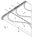
- the Fig. 1 shows a partial view of a center band from a view obliquely from the front.
- Fig. 1 is a center band 2 shown from a view obliquely from above in a section.
- the center belt 2 is driven in the conveying direction F against the direction of travel of the harvester into the standing stock of the crop into endlessly circulating.
- the center belt 2 has lateral edges 4.
- the cut crop is conveyed to the center belt 2 in a draper-header of lateral belt conveyors which drop the crop over the side edges 4 on the top of the center belt 2.
- the elevations 6 consist of moldings 10, which have a cylindrical basic shape.
- the moldings 10 are lined up at regular intervals to each other.
- the rows 8 are staggered with respect to each other, so that the shaped bodies 10 of a row each cover a gap in the transverse direction, which have shaped bodies 10 of an adjacent row between them.
- the gaps or the free spaces may have a width which is slightly larger than the diameter of a shaped body 10.
- the gaps may also be smaller and even be narrowed to a slot between adjacent blocks of material of a survey, which is only in the circulation area of the center band around a guide roller 12 opens scissor-like, as in Fig. 1 also in the circulation area for the moldings 10 can be seen.
- Deviating the gaps may also reach less deep by the bottom portions of the gaps in the area of the survey 6 on the outwardly facing surface of the center band 2 protruding.
- the middle band bars 14 On the outwardly facing surface of the middle band bars 14 are placed, which extend substantially transversely to the conveying direction of the center band and have over their extent across the center band a waveform.
- the amplitude of the waveform of the ridges placed on the outwardly facing surface of the center band is higher than half the circumference of a pulley of the center band.
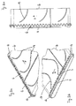
- Fig. 2a, 2b and 2c Views are shown on an alternative embodiment with a arranged in loops lateral grain-locking survey 6.
- the in the Fig. 2a, 2b and 2c shown grain-locking elevation 6 is placed in loops and has over its length a lateral offset transversely to the rotational direction of the center belt 2.
- the tensioned in the direction of rotation F sections of the lateral grain-locking survey 6 can draw material from the material of the looped sections that is not or only slightly exposed to tensile loads. This can be seen in the areas in which the center belt 2 revolves around the pulleys.
Landscapes
- Life Sciences & Earth Sciences (AREA)
- Environmental Sciences (AREA)
- Belt Conveyors (AREA)
Applications Claiming Priority (2)
| Application Number | Priority Date | Filing Date | Title |
|---|---|---|---|
| DE102015116951 | 2015-10-06 | ||
| DE102015117787.0A DE102015117787A1 (de) | 2015-10-06 | 2015-10-19 | Schneidwerk mit Mittenband und zusätzlicher Körnerverlustsicherung |
Publications (1)
| Publication Number | Publication Date |
|---|---|
| EP3153003A1 true EP3153003A1 (fr) | 2017-04-12 |
Family
ID=57083028
Family Applications (1)
| Application Number | Title | Priority Date | Filing Date |
|---|---|---|---|
| EP16002103.6A Withdrawn EP3153003A1 (fr) | 2015-10-06 | 2016-09-29 | Barre de coupe comprenant une bande centrale et un dispositif auxiliaire destiné à limiter la perte de grains |
Country Status (1)
| Country | Link |
|---|---|
| EP (1) | EP3153003A1 (fr) |
Cited By (2)
| Publication number | Priority date | Publication date | Assignee | Title |
|---|---|---|---|---|
| US20240008410A1 (en) * | 2022-07-05 | 2024-01-11 | CLAAS Hungária Kft. | Draper |
| EP4309489A1 (fr) * | 2022-07-21 | 2024-01-24 | CLAAS Hungária Kft. | Coupeuse de bande |
Citations (5)
| Publication number | Priority date | Publication date | Assignee | Title |
|---|---|---|---|---|
| GB2146217A (en) * | 1983-09-09 | 1985-04-17 | Kubota Ltd | Combine harvester |
| US6351931B1 (en) * | 2000-06-09 | 2002-03-05 | Macdon Industries Ltd. | Crop header with draper canvas |
| US20040148919A1 (en) * | 2003-01-11 | 2004-08-05 | Dunn James Thomas | Crop feed draper for a header |
| EP2420125A1 (fr) * | 2010-08-20 | 2012-02-22 | Grimme Landmaschinenfabrik GmbH & Co. KG | Dispositif de transport pour machines de récolte de fruits hachés |
| EP2896283A2 (fr) * | 2014-01-15 | 2015-07-22 | Deere & Company | Tablier de coupe à fléchissement avec agencement de courroie de nettoyage |
-
2016
- 2016-09-29 EP EP16002103.6A patent/EP3153003A1/fr not_active Withdrawn
Patent Citations (5)
| Publication number | Priority date | Publication date | Assignee | Title |
|---|---|---|---|---|
| GB2146217A (en) * | 1983-09-09 | 1985-04-17 | Kubota Ltd | Combine harvester |
| US6351931B1 (en) * | 2000-06-09 | 2002-03-05 | Macdon Industries Ltd. | Crop header with draper canvas |
| US20040148919A1 (en) * | 2003-01-11 | 2004-08-05 | Dunn James Thomas | Crop feed draper for a header |
| EP2420125A1 (fr) * | 2010-08-20 | 2012-02-22 | Grimme Landmaschinenfabrik GmbH & Co. KG | Dispositif de transport pour machines de récolte de fruits hachés |
| EP2896283A2 (fr) * | 2014-01-15 | 2015-07-22 | Deere & Company | Tablier de coupe à fléchissement avec agencement de courroie de nettoyage |
Cited By (3)
| Publication number | Priority date | Publication date | Assignee | Title |
|---|---|---|---|---|
| US20240008410A1 (en) * | 2022-07-05 | 2024-01-11 | CLAAS Hungária Kft. | Draper |
| EP4305951A1 (fr) * | 2022-07-05 | 2024-01-17 | CLAAS Hungária Kft. | Barre de coupe à tapis |
| EP4309489A1 (fr) * | 2022-07-21 | 2024-01-24 | CLAAS Hungária Kft. | Coupeuse de bande |
Similar Documents
| Publication | Publication Date | Title |
|---|---|---|
| DE102015117787A1 (de) | Schneidwerk mit Mittenband und zusätzlicher Körnerverlustsicherung | |
| EP1977984A1 (fr) | Dispositif d'acheminement pour produits en vrac | |
| DE69401580T2 (de) | Stabband | |
| EP2420125A1 (fr) | Dispositif de transport pour machines de récolte de fruits hachés | |
| DE102019213022A1 (de) | Fördersystem | |
| DE102018108877A1 (de) | Siebbandeinheit | |
| DE1582642A1 (de) | Maehdrescher | |
| DE69014465T2 (de) | Eine Hebetransportvorrichtung und ein landwirtschaftliches Trennungsgerät, das eine Hebetransportvorrichtung umfasst. | |
| CH628776A5 (en) | Belt for screening chain conveyors of potato-harvesting machines | |
| DE3419516C2 (fr) | ||
| DE2248445A1 (de) | Plattenbandfoerderer fuer maehdrescher oder dergleichen | |
| EP0920797A1 (fr) | Transporteur incliné pour machines de récolte agricoles | |
| DE102013004859A1 (de) | Mäh- und Einzugseinrichtung zum Schneiden und Abfördern von stängeligem Erntegut | |
| EP0059950B1 (fr) | Récolteuse de pommes de terre | |
| DE2312111C2 (de) | Kartoffelerntemaschine | |
| EP0562541B1 (fr) | Dispositif pour séparer des croissances secondaires et/ou des racines des bulbes | |
| DE3109209C2 (de) | Kartoffelerntemaschine | |
| DE2345494A1 (de) | Sammelblech-anordnung bei einem kolbenpflueck-vorsatzgeraet | |
| DE3636668C2 (fr) | ||
| DE2213570A1 (de) | Schneidmesserbefestigung bei einem Bandmähwerk | |
| DE2347425C3 (de) | Gerät zum Aufsammeln faseriger oder langfibriger Bestandteile aus einer flüssigkeitsdurchströmten Rinne | |
| EP3160875B1 (fr) | Dispositif servant à rendre étanches des zones latérales d'un convoyeur à bande et installation de convoyeurs à bande | |
| DE2828641C2 (fr) | ||
| DE2840016B1 (de) | Sortiermaschine,insbesondere zur Quadratsortierung von landwirtschaftlichen Produkten | |
| CH191377A (de) | Fördervorrichtung für pulverförmiges, körniges oder stückiges Massengut. |
Legal Events
| Date | Code | Title | Description |
|---|---|---|---|
| PUAI | Public reference made under article 153(3) epc to a published international application that has entered the european phase |
Free format text: ORIGINAL CODE: 0009012 |
|
| AK | Designated contracting states |
Kind code of ref document: A1 Designated state(s): AL AT BE BG CH CY CZ DE DK EE ES FI FR GB GR HR HU IE IS IT LI LT LU LV MC MK MT NL NO PL PT RO RS SE SI SK SM TR |
|
| AX | Request for extension of the european patent |
Extension state: BA ME |
|
| 17P | Request for examination filed |
Effective date: 20170509 |
|
| RBV | Designated contracting states (corrected) |
Designated state(s): AL AT BE BG CH CY CZ DE DK EE ES FI FR GB GR HR HU IE IS IT LI LT LU LV MC MK MT NL NO PL PT RO RS SE SI SK SM TR |
|
| 17Q | First examination report despatched |
Effective date: 20171106 |
|
| STAA | Information on the status of an ep patent application or granted ep patent |
Free format text: STATUS: THE APPLICATION HAS BEEN WITHDRAWN |
|
| 18W | Application withdrawn |
Effective date: 20171208 |