EP3153148B1 - Vorrichtung zur sexuellen stimulation - Google Patents
Vorrichtung zur sexuellen stimulation Download PDFInfo
- Publication number
- EP3153148B1 EP3153148B1 EP15189137.1A EP15189137A EP3153148B1 EP 3153148 B1 EP3153148 B1 EP 3153148B1 EP 15189137 A EP15189137 A EP 15189137A EP 3153148 B1 EP3153148 B1 EP 3153148B1
- Authority
- EP
- European Patent Office
- Prior art keywords
- stimulation
- main body
- stimulation body
- longitudinal axis
- magnets
- Prior art date
- Legal status (The legal status is an assumption and is not a legal conclusion. Google has not performed a legal analysis and makes no representation as to the accuracy of the status listed.)
- Active
Links
Images


Classifications
-
- A—HUMAN NECESSITIES
- A61—MEDICAL OR VETERINARY SCIENCE; HYGIENE
- A61H—PHYSICAL THERAPY APPARATUS, e.g. DEVICES FOR LOCATING OR STIMULATING REFLEX POINTS IN THE BODY; ARTIFICIAL RESPIRATION; MASSAGE; BATHING DEVICES FOR SPECIAL THERAPEUTIC OR HYGIENIC PURPOSES OR SPECIFIC PARTS OF THE BODY
- A61H19/00—Massage for the genitals; Devices for improving sexual intercourse
- A61H19/40—Devices insertable in the genitals
- A61H19/44—Having substantially cylindrical shape, e.g. dildos
-
- A—HUMAN NECESSITIES
- A61—MEDICAL OR VETERINARY SCIENCE; HYGIENE
- A61H—PHYSICAL THERAPY APPARATUS, e.g. DEVICES FOR LOCATING OR STIMULATING REFLEX POINTS IN THE BODY; ARTIFICIAL RESPIRATION; MASSAGE; BATHING DEVICES FOR SPECIAL THERAPEUTIC OR HYGIENIC PURPOSES OR SPECIFIC PARTS OF THE BODY
- A61H21/00—Massage devices for cavities of the body, e.g. nose, ears and anus ; Vibration or percussion related aspects A61H23/00
-
- A—HUMAN NECESSITIES
- A61—MEDICAL OR VETERINARY SCIENCE; HYGIENE
- A61H—PHYSICAL THERAPY APPARATUS, e.g. DEVICES FOR LOCATING OR STIMULATING REFLEX POINTS IN THE BODY; ARTIFICIAL RESPIRATION; MASSAGE; BATHING DEVICES FOR SPECIAL THERAPEUTIC OR HYGIENIC PURPOSES OR SPECIFIC PARTS OF THE BODY
- A61H23/00—Percussion or vibration massage, e.g. using supersonic vibration; Suction-vibration massage; Massage with moving diaphragms
-
- A—HUMAN NECESSITIES
- A61—MEDICAL OR VETERINARY SCIENCE; HYGIENE
- A61H—PHYSICAL THERAPY APPARATUS, e.g. DEVICES FOR LOCATING OR STIMULATING REFLEX POINTS IN THE BODY; ARTIFICIAL RESPIRATION; MASSAGE; BATHING DEVICES FOR SPECIAL THERAPEUTIC OR HYGIENIC PURPOSES OR SPECIFIC PARTS OF THE BODY
- A61H2201/00—Characteristics of apparatus not provided for in the preceding codes
- A61H2201/01—Constructive details
- A61H2201/0119—Support for the device
- A61H2201/0153—Support for the device hand-held
-
- A—HUMAN NECESSITIES
- A61—MEDICAL OR VETERINARY SCIENCE; HYGIENE
- A61H—PHYSICAL THERAPY APPARATUS, e.g. DEVICES FOR LOCATING OR STIMULATING REFLEX POINTS IN THE BODY; ARTIFICIAL RESPIRATION; MASSAGE; BATHING DEVICES FOR SPECIAL THERAPEUTIC OR HYGIENIC PURPOSES OR SPECIFIC PARTS OF THE BODY
- A61H2201/00—Characteristics of apparatus not provided for in the preceding codes
- A61H2201/01—Constructive details
- A61H2201/0192—Specific means for adjusting dimensions
-
- A—HUMAN NECESSITIES
- A61—MEDICAL OR VETERINARY SCIENCE; HYGIENE
- A61H—PHYSICAL THERAPY APPARATUS, e.g. DEVICES FOR LOCATING OR STIMULATING REFLEX POINTS IN THE BODY; ARTIFICIAL RESPIRATION; MASSAGE; BATHING DEVICES FOR SPECIAL THERAPEUTIC OR HYGIENIC PURPOSES OR SPECIFIC PARTS OF THE BODY
- A61H2201/00—Characteristics of apparatus not provided for in the preceding codes
- A61H2201/14—Special force transmission means, i.e. between the driving means and the interface with the user
- A61H2201/1481—Special movement conversion means
- A61H2201/149—Special movement conversion means rotation-linear or vice versa
-
- A—HUMAN NECESSITIES
- A61—MEDICAL OR VETERINARY SCIENCE; HYGIENE
- A61H—PHYSICAL THERAPY APPARATUS, e.g. DEVICES FOR LOCATING OR STIMULATING REFLEX POINTS IN THE BODY; ARTIFICIAL RESPIRATION; MASSAGE; BATHING DEVICES FOR SPECIAL THERAPEUTIC OR HYGIENIC PURPOSES OR SPECIFIC PARTS OF THE BODY
- A61H2201/00—Characteristics of apparatus not provided for in the preceding codes
- A61H2201/16—Physical interface with patient
- A61H2201/1602—Physical interface with patient kind of interface, e.g. head rest, knee support or lumbar support
- A61H2201/1645—Physical interface with patient kind of interface, e.g. head rest, knee support or lumbar support contoured to fit the user
-
- A—HUMAN NECESSITIES
- A61—MEDICAL OR VETERINARY SCIENCE; HYGIENE
- A61H—PHYSICAL THERAPY APPARATUS, e.g. DEVICES FOR LOCATING OR STIMULATING REFLEX POINTS IN THE BODY; ARTIFICIAL RESPIRATION; MASSAGE; BATHING DEVICES FOR SPECIAL THERAPEUTIC OR HYGIENIC PURPOSES OR SPECIFIC PARTS OF THE BODY
- A61H2201/00—Characteristics of apparatus not provided for in the preceding codes
- A61H2201/16—Physical interface with patient
- A61H2201/1683—Surface of interface
- A61H2201/169—Physical characteristics of the surface, e.g. material, relief, texture or indicia
- A61H2201/1695—Enhanced pressure effect, e.g. substantially sharp projections, needles or pyramids
-
- A—HUMAN NECESSITIES
- A61—MEDICAL OR VETERINARY SCIENCE; HYGIENE
- A61H—PHYSICAL THERAPY APPARATUS, e.g. DEVICES FOR LOCATING OR STIMULATING REFLEX POINTS IN THE BODY; ARTIFICIAL RESPIRATION; MASSAGE; BATHING DEVICES FOR SPECIAL THERAPEUTIC OR HYGIENIC PURPOSES OR SPECIFIC PARTS OF THE BODY
- A61H2201/00—Characteristics of apparatus not provided for in the preceding codes
- A61H2201/50—Control means thereof
- A61H2201/5002—Means for controlling a set of similar massage devices acting in sequence at different locations on a patient
-
- A—HUMAN NECESSITIES
- A61—MEDICAL OR VETERINARY SCIENCE; HYGIENE
- A61H—PHYSICAL THERAPY APPARATUS, e.g. DEVICES FOR LOCATING OR STIMULATING REFLEX POINTS IN THE BODY; ARTIFICIAL RESPIRATION; MASSAGE; BATHING DEVICES FOR SPECIAL THERAPEUTIC OR HYGIENIC PURPOSES OR SPECIFIC PARTS OF THE BODY
- A61H2201/00—Characteristics of apparatus not provided for in the preceding codes
- A61H2201/50—Control means thereof
- A61H2201/5007—Control means thereof computer controlled
- A61H2201/501—Control means thereof computer controlled connected to external computer devices or networks
-
- A—HUMAN NECESSITIES
- A61—MEDICAL OR VETERINARY SCIENCE; HYGIENE
- A61H—PHYSICAL THERAPY APPARATUS, e.g. DEVICES FOR LOCATING OR STIMULATING REFLEX POINTS IN THE BODY; ARTIFICIAL RESPIRATION; MASSAGE; BATHING DEVICES FOR SPECIAL THERAPEUTIC OR HYGIENIC PURPOSES OR SPECIFIC PARTS OF THE BODY
- A61H2201/00—Characteristics of apparatus not provided for in the preceding codes
- A61H2201/50—Control means thereof
- A61H2201/5097—Control means thereof wireless
-
- A—HUMAN NECESSITIES
- A61—MEDICAL OR VETERINARY SCIENCE; HYGIENE
- A61H—PHYSICAL THERAPY APPARATUS, e.g. DEVICES FOR LOCATING OR STIMULATING REFLEX POINTS IN THE BODY; ARTIFICIAL RESPIRATION; MASSAGE; BATHING DEVICES FOR SPECIAL THERAPEUTIC OR HYGIENIC PURPOSES OR SPECIFIC PARTS OF THE BODY
- A61H23/00—Percussion or vibration massage, e.g. using supersonic vibration; Suction-vibration massage; Massage with moving diaphragms
- A61H23/02—Percussion or vibration massage, e.g. using supersonic vibration; Suction-vibration massage; Massage with moving diaphragms with electric or magnetic drive
- A61H23/0254—Percussion or vibration massage, e.g. using supersonic vibration; Suction-vibration massage; Massage with moving diaphragms with electric or magnetic drive with rotary motor
- A61H23/0263—Percussion or vibration massage, e.g. using supersonic vibration; Suction-vibration massage; Massage with moving diaphragms with electric or magnetic drive with rotary motor using rotating unbalanced masses
Definitions
- the invention relates to a device for sexual stimulation of the human body, comprising a phallus-like shaped stimulation body, which is partially variable in thickness and for sectionally changing the thickness has a stimulation element, wherein the stimulation element has at least one magnetic holding means.
- Such a device goes out of the WO 2005/041845 A1 which describes a stimulator having a phallic shape.
- a cavity is formed in the stimulator in which a permanent magnet can be moved back and forth by means of a drive.
- the permanent magnet abuts other permanent magnets that are movably mounted on the stimulator so that they are moved as the permanent magnet is moved past them, thereby creating a stimulating effect.
- a stimulation effect can be achieved by a vibration of the stimulation body.
- the present invention has for its object to provide a device of the type mentioned, which allows a different stimulation effect than the known devices.
- the object is achieved in that within the stimulation body at least one magnetic carrier for the stimulation element is movably arranged, which is intended to entrain the magnetic holding means of the stimulation element in the longitudinal direction of the stimulation body when it is moved within the stimulation body in the longitudinal direction.
- the driver is expediently movable parallel and / or transversely to the longitudinal axis of the stimulation body and pulls the stimulation element with it when it is moved in the stimulation body.
- a sexual stimulus can be generated with the device, which mimics a stimulation by a male member particularly well. Additional manual movement of the stimulation body is not necessary.
- the stimulation element is exchangeable, is movable on a base body of the stimulation body, preferably in the direction of the longitudinal axis of the stimulation body and / or in the circumferential direction of the stimulation body, and forms a bulge on the base body.
- a movement direction and / or a movement speed with which the stimulation element is movable on the base body in the direction of the longitudinal axis and / or in the circumferential direction are preferably independently of one another, controllable, and / or, preferably stepless, adjustable.
- the device may comprise different replaceable stimulation elements for different stimulation effects.
- the stimulation element is expediently provided such that it rests against the outside of the base body.
- the stimulation body is expediently encased by a sheath, which is preferably formed from a flexible plastic, preferably latex and / or silicone.
- the sheath is preferably removable from the device to allow replacement of the stimulation element with another stimulation element.
- the stimulation element expediently has a length in the longitudinal direction of the stimulation body which corresponds to one thirtieth to one tenth of the total length of the stimulation body. Other lengths are conceivable, but the stimulation element should be at most half as long as the entire stimulation body.
- the stimulation element is annular, preferably as a ring completely encompassing the main body, which may be provided with a uniform or changing outer diameter seen over its circumference.
- an outer shape of the ring can be wavy or have nubs to achieve an additional stimulation effect.
- the stimulation element as seen in the circumferential direction, comprises spaced-apart individual elements forming the bulge, which are preferably formed by spherical segments.
- At least one projection is expediently provided on a side of the stimulation element facing the base body, which projection engages in a guide groove which is formed on the outer side of the main body, wherein the guide groove is preferably formed transversely to the longitudinal axis, particularly preferably helically around the longitudinal axis of the main body. to allow a guided movement of the stimulation element along a path of movement formed by the guide groove. If the driver takes along the stimulation element by virtue of its movement along the longitudinal axis within the stimulation body, the stimulation element is also moved transversely to the longitudinal axis because the projection is guided along the guide groove. Thanks to the magnetic holding force between the driver and the stimulation element, it is not necessary to move the driver transverse to the longitudinal axis in order to achieve a corresponding movement of the stimulation element.
- the stimulation element comprises at and / or arranged in the shell permanent magnets and within the stimulation body is at least one magnetic repulsion element, which is polarized opposite to the permanent magnet, movably arranged. If the repulsion element is moved in the vicinity of the permanent magnets, they are repelled, thereby bulging the shell. If a plurality of permanent magnets are arranged on or in the shell, it can be achieved by moving the repulsion element in the direction of the longitudinal axis of the stimulation body that a bulge created by repulsion of the permanent magnets shifts with the movement of the repulsion element.
- a device for moving the stimulation element which comprises a drive unit for a carriage which can be moved within the stimulation body, on which the anvil or the repulsion element is arranged.
- the stimulation body has a guide device, preferably at least one guide rail, along which the carriage is movable back and forth, wherein the guide device is preferably arranged parallel, particularly preferably coaxially, to the longitudinal axis of the stimulation body.
- the guide device could be formed as a threaded rod along which the carriage can move.
- the stimulation body comprises a length-change element, which is movable in the axial direction in relation to a base body of the stimulation body for lengthening or shortening of the stimulation body.
- the length-changing element has a hollow cylinder which is mounted on the base body and displaceable on this.
- a threaded spindle is provided for movement of the length-changing element.
- a thread is formed on an inner side of the length-changing element, in which engages a thrust member which is rotated by a drive about the longitudinal axis of the base body and thereby displaces the length-changing element against the base body.
- the stimulation body is provided for varying its length with permanent magnets which can be arranged in a starting position in which they attract each other, and in an extension position in which they repel each other.
- the length-changing element can be moved by movement of the permanent magnets between the starting position and the extension position on the base body.
- At least one of the permanent magnets is arranged on at least one telescopically extendable holding means and one end of the holding means is connected to the base body and the other end to the length-changing element.
- the movable extension element could be provided with a vibration device by means of which it can be put into vibration. It should be understood that said sheath is adapted to accommodate the change in the length of the stimulation body. It can be provided for flexible or partially foldable.
- the device is provided such that the change in length and the change in thickness of the stimulation body, if necessary separately, can be controlled and / or adjusted.
- the device is remotely controllable. It is expediently provided with a receiving device, preferably a radio receiver, eg for WLAN or Bluetooth, which cooperates with a control device for the device.
- the device may have its own remote control device, but it would also be conceivable to provide the device in such a way that it can be controlled by means of a mobile telephone or another computer, in particular also via a network.
- the device may also include a computer program for the mobile phone or the computer intended for its control.
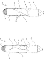
- An in Fig. 1 shown device 1 comprises a phallus-shaped stimulation body 2 and a handle 4 with openings for engagement with one finger. On the handle 4 switching buttons 5 are arranged, with which the device 1 can be switched on and off and controlled.
- the stimulation body 2 has a bulge 6, which by Fig. 2 shown under a surrounding the stimulation body 2 envelope 7 nubs 12 is generated.
- the sheath 7 comprises in an upper part of the stimulation body 2 a folded-over section 8 which can be unfolded when the stimulation body 2 is extended.
- vent openings 9 are provided, through the air in the shortening of the extension of the stimulation body 2 or can flow out.
- the main body 3 forms a portion of the outer surface of the stimulation body 2, along which the nubs 12, which may be formed, for example, by spherical segments or the like, are movable.
- the stimulation body 2 can be extended or shortened by movement of the hollow cylinder 10.
- drive rod 14 which is rotatable by means of a drive 13 about the longitudinal axis of the stimulation body 2 and at the ends of rollers 15 are mounted, which engage in a formed in the hollow cylinder 10 internal thread 16.
- Fig. 4 shows the stimulation body 2 in an extended state in which the portion 8 of the silicone sheath 7 is unfolded.
- a weight 17 may be attached at a distance from the axis of rotation, which causes an imbalance in their rotation.
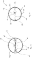
- An in Fig. 2 shown electric drive 18 is provided for rotation of a threaded rod 19 which is arranged coaxially to the longitudinal axis of the stimulation body 2 and is rotatably connected at its upper end to the stimulation body 2.
- a carriage 20 can move, which is connected by means of a nut with the threaded rod 19 and attached to the magnets 21.
- the magnets 21 form magnetic counter-holders for magnets, not shown here, which are arranged on the knobs 12 and are attracted by the magnets 21.
- the magnets 21 Upon movement of the carriage 20 along the threaded rod 19, the magnets 21 take the nubs 12, so that the nubs 12 are moved in the longitudinal direction of the stimulation body 2 along the outside of the stimulation body 2.
- FIGS. 5 to 16 Reference is made to the same or equivalent parts with the same reference number as in Fig. 1 and 2 and the relevant reference number is accompanied by a letter.
- FIG. 5 The device 1a shown differs from that according to FIGS. 1 to 4 in that four grooves 22 are formed on an outside of a stimulation body 2a, which grooves extend in the longitudinal direction of the stimulation element 2a and have a curved shape.
- a nub 12 a which is provided on its side facing the stimulation body 2 a side with a projection, not shown here, which engages in the groove 22.
- magnets 21a moves take the magnets 21a due to magnetic attraction of the nubs 12a with the nubs 12a are pulled along the groove 22 and thus not only in the longitudinal direction of the stimulation body 2a, but also across it to be moved.
- a ring 23 is arranged on a stimulation body 2b, on the outside in the circumferential direction seen at a distance from each other groups of three nubs 12b are formed.
- a groove 22b arranged transversely to the longitudinal axis of the stimulation body 2b is formed, into which the ring 23 engages with a projection (not shown here) formed on its inner side.
- Fig. 7 shows a further device 1c according to the invention, which differs from the devices according to the FIGS. 1 to 6 differs in that a bulge 6c formed on an outer surface of a stimulation body 2c by an air cushion 30, which forms between the stimulation body 2c and a sheath 7c as explained below.
- a bulge 6c formed on an outer surface of a stimulation body 2c by an air cushion 30, which forms between the stimulation body 2c and a sheath 7c as explained below.
- a plurality of flat permanent magnets 24 are spaced apart and evenly distributed. Will be like on the basis of FIGS. 1 to 4 Explained inside the stimulation body 2c moves a magnet 21c, which is polarized opposite to the permanent magnet 24, the permanent magnets 24 are repelled and book the sleeve 7c.
- the bulge 6c accordingly moves with the magnet 21c.
- Fig. 8 shows a cross section through a stimulation body 2d with a drive means 25 of another device 1d according to the invention, which arranged in the longitudinal direction of the stimulation body 2d, by means of a in Fig. 2 shown drive 18 rotatable threaded rod 19d, on the movable a double nut 26 is arranged.
- drive 18 rotatable threaded rod 19d, on the movable a double nut 26 is arranged.
- Fixedly connected to the double nut 26 are linkage elements 27, on the inside of the stimulation body 2d ends facing magnets 28 are mounted, which engage with a projection 29 in a provided on the inside of the stimulation body 2d thread.
- the projection 29 could instead of the thread in a on the inside of the stimulation body 2 d introduced, preferably transversely to the longitudinal direction stimulation body 2 d extending groove (not shown) engage, so that the distance at which the nubs are moved 12 d, the course of the Groove depends. It is understood that the groove as above based on the FIGS. 5 and 6 illustrated, helically formed or could have a curved shape.
- Fig. 9 shows a cross section through a stimulation body 2e another device 1e according to the invention, which differs from the in Fig. 8 differs in that a local bulge 6e of a sheath 7e is formed by a formed between stimulation body 2e and a sheath 7e air cushion 30e.
- the air cushion 30e forms, as above based on the Fig. 7 illustrated by magnetic repulsive forces between permanent magnets 24e, which are arranged in the sheath 7e and provided inside the stimulation body 2e magnets 28e.
- FIGS. 10 and 11 shows in a further embodiment, a way to move magnets 21f inside a stimulation body 2f another device according to the invention 1f to move nubs 12f or arranged in a shell magnets to form an air cushion.
- the magnets 21f are fixed to a carriage 20f which is like Fig. 11 in more detail, has four wheels 31 which can travel along a rod 32 as the carriage 20f moves.
- the carriage 20f is further connected to a toothed belt 33, which is guided over two gears 34,35.
- the gear 34 is rotated by means of a drive not shown here, the toothed belt 33 is moved together with the carriage 20f.
- the magnet 21f takes a likewise provided with a magnet 36 nub 12f as explained above.
- the in the FIGS. 10 and 11 described drive device is particularly suitable for stimulation body, which could have a curved shape deviating from the stimulation bodies shown in the figures.
- FIGS. 12 to 15 show another mechanism for changing the length of a stimulation body 2g.
- a device for displacing a hollow cylinder 10g In the interior of a base body 3g of the stimulation body 2 g, there is a device for displacing a hollow cylinder 10g.
- the device has an extendable central telescopic rod 37 arranged coaxially to the longitudinal axis of the stimulation body 2g, which is rotatably mounted about its longitudinal axis and can be rotated by means of a drive 13g having a gear 38.
- On the telescopic rod 37 four carriages 39 are arranged at a distance from each other, which is a in Fig. 13 have shown rod member 40, at the ends of magnets 41 are attached.
- adjacent magnets 41 attract each other and be through in Fig. 15 shown spacers 42 held at a distance from each other.
- two extendable rails 43 are provided, on which five carriages 44 are arranged, to which magnets 45 are attached.
- Immediately adjacent magnets 45 attract and are held by spacers 42 at a distance from each other.
- the two rails 43 are over a in Fig. 13 shown web 47 firmly connected.
- the length of the stimulation body 2g can be adjusted.
- the unaltered state ( Fig. 12 ) is the rod member 40 with the arranged at its ends magnet 41 in the in Fig. 13 arranged starting position arranged.
- the telescopic rod 37 is rotated by 90 ° about its longitudinal axis, so that as in Fig. 14 shown the magnets 41 each between the magnets 45 of two adjacent slide 44 push. Since the magnets 41 and 45 are oppositely poled to mutually facing portions, the magnets 41,45 repel each other.
- the hollow cylinder 10g is moved out of the main body 3g and the stimulation body 2g is extended.
- Fig. 15 shows the stimulation element 2g in the extended state with a corresponding arrangement of the magnets 41,45.
- the carriage 44 are moved toward each other again after the rotation of the telescopic rod 37 and the outer guide rails 43 back into the in Fig. 12 pushed back position shown.
- FIG. 16 An in Fig. 16 shown rotatable drive rod 14h another device according to the invention distinguished from the one after Fig. 3 in that a weight 17h is movably arranged in the longitudinal direction of the drive rod 14h.
- a spring 53 is at one end with the weight 17h and at the other End connected to a spring holder 52 of the drive rod 14h.
- the movements of the respective stimulation bodies 2, 2a, 2b, 2c, 2d, 2e, 2f, 2g, 2h and the respective hollow cylinders 10, 10a, 10b, 10c, 10d, 10e, 10f, 10g are controlled independently of each other.
- the control can be done by pressing the control buttons 5,5a.
- the devices could also be provided with a radio receiver so that they could be controlled with a remote control.
- Such a remote control could be formed by a remote control device provided specifically for the device.
- the devices for controlling by means of a computer or a smartphone, possibly via WLAN or Bluetooth, and / or via a computer network. It is also possible that the respective movement speeds can be independently controlled and / or controlled by a user by operating the control buttons 5,5a. It is understood that the stimulation body could deviate from the above-mentioned devices also have a curved shape.
Landscapes
- Health & Medical Sciences (AREA)
- Life Sciences & Earth Sciences (AREA)
- Epidemiology (AREA)
- Pain & Pain Management (AREA)
- Physical Education & Sports Medicine (AREA)
- Rehabilitation Therapy (AREA)
- Animal Behavior & Ethology (AREA)
- General Health & Medical Sciences (AREA)
- Public Health (AREA)
- Veterinary Medicine (AREA)
- Reproductive Health (AREA)
- Otolaryngology (AREA)
- Magnetic Treatment Devices (AREA)
- Percussion Or Vibration Massage (AREA)
Description
- Die Erfindung betrifft eine Vorrichtung zur sexuellen Stimulation des menschlichen Körpers, die einen phallusartig geformten Stimulationskörper umfasst, der abschnittsweise in seiner Dicke veränderbar ist und zur abschnittsweisen Veränderung der Dicke ein Stimulationselement aufweist, wobei das Stimulationselement mindestens ein magnetisches Haltemittel aufweist.
- Eine solche Vorrichtung geht aus der
WO 2005/041845 A1 hervor, die einen Stimulator beschreibt, der eine phallische Form aufweist. Im Stimulator ist ein Hohlraum gebildet, in dem sich ein Permanentmagnet mittels eines Antriebs hin und her bewegen lässt. Der Permanentmagnet stößt andere Permanentmagnete, die beweglich an dem Stimulator befestigt sind ab, so dass sie bewegt werden, wenn der Permanentmagnet an ihnen vorbei bewegt wird und erzeugen dadurch eine stimulierende Wirkung. - Bei weiteren, durch Benutzung bekannten Vorrichtungen der eingangs genannten Art kann eine Stimulationswirkung durch eine Vibration des Stimulationskörpers erreicht werden.
- Der vorliegenden Erfindung liegt die Aufgabe zugrunde, eine Vorrichtung der eingangs genannten Art zu schaffen, die eine andere Stimulationswirkung als die bekannten Vorrichtungen ermöglicht.
- Erfindungsgemäß wird die Aufgabe dadurch gelöst, dass innerhalb des Stimulationskörpers mindestens ein magnetischer Mitnehmer für das Stimulationselement bewegbar angeordnet ist, der dazu vorgesehen ist, das magnetische Haltemittel des Stimulationselements in Längsrichtung des Stimulationskörpers mitzuziehen, wenn er innerhalb des Stimulationskörpers in der Längsrichtung bewegt wird.
- Vorteilhaft muss keine direkte mechanische Verbindung zwischen dem Haltemittel und dem Gegenhalter vorgesehen werden.
- Der Mitnehmer ist zweckmäßigerweise parallel und/oder quer zur Längsachse des Stimulationskörpers bewegbar und zieht das Stimulationselement mit, wenn er im Stimulationskörper bewegt wird.
- Vorteilhaft kann mit der Vorrichtung ein sexueller Reiz erzeugt werden, der eine Stimulation durch ein männliches Glied besonders gut nachahmt. Eine zusätzliche manuelle Bewegung des Stimulationskörpers ist nicht unbedingt notwendig.
- In einer Ausgestaltung der Erfindung ist das Stimulationselement austauschbar, ist auf einem Grundkörper des Stimulationskörpers, vorzugsweise in Richtung der Längsachse des Stimulationskörpers und/oder in Umfangsrichtung des Stimulationskörpers, bewegbar und bildet auf dem Grundkörper eine Auswölbung bildet.
- Zweckmäßigerweise sind eine Bewegungsrichtung und/oder eine Bewegungsgeschwindigkeit, mit der das Stimulationselement auf dem Grundkörper in Richtung der Längsachse und/oder in der Umfangsrichtung bewegbar ist, vorzugsweise unabhängig voneinander, steuerbar, und/oder, vorzugsweise stufenlos, einstellbar. Die Vorrichtung kann unterschiedliche, auswechselbare Stimulationselemente für verschiedene Stimulationswirkungen umfassen. Das Stimulationselement ist zweckmäßigerweise derart vorgesehen, dass es gegen die Außenseite des Grundkörpers anliegt.
- Der Stimulationskörper ist zweckmäßigerweise von einer Hülle ummantelt, die vorzugsweise aus einem flexiblen Kunststoff, vorzugsweise Latex und/oder Silikon, gebildet ist. Die Hülle ist vorzugsweise von der Vorrichtung abnehmbar, um einen Austausch des Stimulationselements gegen ein anderes Stimulationselement zu ermöglichen.
- Zweckmäßigerweise weist das Stimulationselements in Längsrichtung des Stimulationskörpers eine Länge auf, die einem Dreißigstel bis zu einem Zehntel der Gesamtlänge des Stimulationskörpers entspricht. Es sind auch andere Längen vorstellbar, das Stimulationselement sollte aber maximal halb so lang sein wie der gesamte Stimulationskörper.
- In einer Ausgestaltung der Erfindung ist das Stimulationselement ringförmig ausgebildet, vorzugsweise als ein den Grundkörper vollständig umgreifender Ring, der mit einem über seinen Umfang gesehen einheitlichen oder sich ändernden Außendurchmesser versehen sein kann. Beispielsweise kann eine äußere Form des Rings wellenförmig gestaltet sein oder Noppen aufweisen, um eine zusätzliche Stimulationswirkung zu erzielen.
- In einer weiteren Ausführungsform der Erfindung umfasst das Stimulationselement in Umfangsrichtung gesehen im Abstand voneinander angeordnete, die Auswölbung bildende Einzelelemente, die vorzugsweise durch Kugelsegmente gebildet sind.
- Zweckmäßigerweise ist auf einer dem Grundkörper zugewandten Seite des Stimulationselements mindestens ein Vorsprung vorgesehen, der in eine Führungsnut, die auf der Außenseite des Grundkörpers gebildet ist, eingreift, wobei die Führungsnut vorzugsweise quer zur Längsachse, besonders bevorzugt wendelförmig um die Längsachse des Grundkörpers gebildet ist, um eine geführte Bewegung des Stimulationselements entlang einer durch die Führungsnut gebildeten Bewegungsbahn zu ermöglichen. Nimmt der Mitnehmer durch seine Bewegung entlang der Längsachse innerhalb des Stimulationskörpers das Stimulationselement mit, wird dadurch, dass der Vorsprung entlang der Führungsnut geführt wird, das Stimulationselement auch quer zur Längsachse bewegt. Dank der magnetischen Haltekraft zwischen dem Mitnehmer und dem Stimulationselement ist es nicht notwendig, auch den Mitnehmer quer zur Längsachse zu bewegen, um eine entsprechende Bewegung des Stimulationselements zu erreichen.
- In einer weiteren Ausgestaltung der Erfindung umfasst das Stimulationselement an oder/und in der Hülle angeordnete Permanentmagnete und innerhalb des Stimulationskörpers ist mindestens ein magnetisches Abstoßungselement, das entgegengesetzt zu den Permanentmagneten gepolt ist, bewegbar angeordnet. Wird das Abstoßungselement in die Nähe der Permanentmagnete bewegt, werden diese abgestoßen und dadurch die Hülle ausgewölbt. Sind an bzw. in der Hülle mehrere Permanentmagnete angeordnet, kann durch Bewegen des Abstoßungselements in Richtung der Längsachse des Stimulationskörpers erreicht werden, dass sich eine durch Abstoßung der Permanentmagnete erzeugte Auswölbung mit der Bewegung des Abstoßungselements verschiebt.
- In einer Ausgestaltung der Erfindung ist eine Einrichtung zur Bewegung des Stimulationselements vorgesehen, die eine Antriebseinheit für einen innerhalb des Stimulationskörpers bewegbaren Schlitten umfasst, an dem der Gegenhalter oder das Abstoßungselement angeordnet ist.
- In einer weiteren Ausführungsform weist der Stimulationskörper eine Führungseinrichtung, vorzugsweise mindestens eine Führungsschiene, auf, entlang derer der Schlitten hin und her bewegbar ist, wobei die Führungseinrichtung vorzugsweise parallel, besonders bevorzugt koaxial, zur Längsachse des Stimulationskörpers angeordnet ist. Alternativ könnte die Führungseinrichtung als Gewindestange ausgebildet sein, entlang der sich der Schlitten bewegen kann.
- In einer weiteren Ausgestaltung der Erfindung umfasst der Stimulationskörper ein Längenveränderungselement, das zur Verlängerung oder Verkürzung des Stimulationskörpers in axialer Richtung im Verhältnis zu einem Grundkörper des Stimulationskörpers bewegbar ist. Vorzugsweise weist das Längenveränderungselement einen Hohlzylinder auf, der an dem Grundkörper gelagert und an diesem verschiebbar ist.
- In einer Ausgestaltung der Erfindung ist zur Bewegung des Längenveränderungselements eine Gewindespindel vorgesehen. Vorzugsweise ist auf einer Innenseite des Längenveränderungselements ein Gewinde gebildet, in das ein Schubglied eingreift, das mittels eines Antriebs um die Längsachse des Grundkörpers gedreht wird und dadurch das Längenveränderungselement gegen den Grundkörper verschiebt.
- In einer bevorzugten Ausführungsform der Erfindung ist der Stimulationskörper zur Veränderung seiner Länge mit Permanentmagneten versehen, die sich in einer Ausgangsposition, in der sie sich gegenseitig anziehen, und in einer Verlängerungsposition, in der sie sich gegenseitig abstoßen, anordnen lassen. Durch Anordnung der Permanentmagnete in der jeweiligen Position lässt sich das Längenveränderungselement durch Bewegung der Permanentmagnete zwischen der Ausgangsposition und der Verlängerungsposition auf dem Grundkörper bewegen.
- Zweckmäßigerweise ist zumindest einer der Permanentmagnete an zumindest einem teleskopartig verlängerbaren Haltemittel angeordnet und ein Ende des Haltemittels ist mit dem Grundkörper und das andere Ende mit dem Längenveränderungselement verbunden.
Zur zusätzlichen Stimulation könnte das bewegbare Verlängerungselement mit einer Vibrationseinrichtung versehen sein, mittels derer es sich in Vibration versetzen lässt. Es versteht sich, dass die genannte Hülle dazu eingerichtet ist, sich an die Veränderung der Länge des Stimulationskörpers anzupassen. Sie kann dazu flexibel oder teilweise faltbar vorgesehen sein. - In einer besonderen Ausgestaltung der Erfindung ist die Vorrichtung derart vorgesehen, dass die Längenveränderung und die Dickenveränderung des Stimulationskörpers, ggf. separat, steuer- und/oder einstellbar ist.
In einer weiteren Ausgestaltung der Erfindung ist die Vorrichtung fernsteuerbar. Sie ist dazu zweckmäßigerweise mit einer Empfangseinrichtung, vorzugsweise einem Funkempfänger, z.B. für WLAN oder Bluetooth, versehen, der mit einer Steuerungseinrichtung für die Vorrichtung, zusammenwirkt. Die Vorrichtung kann eine eigene Fernsteuerungseinrichtung aufweisen, vorstellbar wäre aber auch, die Vorrichtung derart vorzusehen, dass sie mittels eines Mobiltelefons oder eines anderen Computers, insbesondere auch über ein Netzwerk, steuerbar ist. Die Vorrichtung kann auch ein für ihre Steuerung vorgesehenes Computerprogramm für das Mobiltelefon oder den Computer umfassen. - Die Erfindung wird nachfolgend anhand von Ausführungsbeispielen und der beiliegenden, sich auf diese Ausführungsbeispiele beziehenden Zeichnungen näher erläutert. Es zeigen:
- Fig. 1
- eine Seitenansicht auf eine erfindungsgemäße Vorrichtung,
- Fig. 2
- einen teilweisen Längsschnitt durch die Vorrichtung nach
Fig. 1 , - Fig. 3
- einen Querschnitt durch den Stimulationskörper nach
Fig. 1 , - Fig. 4
- einen teilweisen Längsschnitt durch die Vorrichtung nach
Fig. 1 in einer anderen Stellung, - Fig. 5
- eine weitere erfindungsgemäße Vorrichtung,
- Fig. 6
- eine weitere erfindungsgemäße Vorrichtung,
- Fig. 7
- eine weitere erfindungsgemäße Vorrichtung,
- Fig. 8
- einen Querschnitt durch einen Stimulationskörper einer weiteren erfindungsgemäßen Vorrichtung,
- Fig. 9
- einen Querschnitt durch einen Stimulationskörper einer weiteren erfindungsgemäßen Vorrichtung,
- Fig. 10
- einen Teil einer weiteren erfindungsgemäßen Vorrichtung,
- Fig. 11
- ein Detail der Vorrichtung nach
Fig. 10 , - Fig. 12
- eine weitere erfindungsgemäße Vorrichtung in einem Längsschnitt,
- Fig. 13 und 14
- die Vorrichtung nach
Fig. 12 in verschiedenen Stellungen im Querschnitt, - Fig. 15
- die Vorrichtung nach
Fig. 12 in einer anderen Stellung im Längsschnitt, und - Fig. 16
- eine weitere erfindungsgemäße Vorrichtung im Querschnitt.
- Eine in
Fig. 1 gezeigte Vorrichtung 1 umfasst einen phallusartig geformten Stimulationskörper 2 und ein Griffstück 4 mit Öffnungen zum Eingriff mit je einem Finger. An dem Griffstück 4 sind Schaltknöpfe 5 angeordnet, mit denen die Vorrichtung 1 ein- und ausgeschaltet sowie gesteuert werden kann.
Der Stimulationskörper 2 weist eine Ausbuchtung 6 auf, die durch inFig. 2 gezeigte unter einer den Stimulationskörper 2 umgebenden Hülle 7 angeordnete Noppen 12 erzeugt wird. Die Hülle 7 umfasst in einem oberen Teil des Stimulationskörpers 2 einen zusammengefalteten Abschnitt 8, der bei Verlängerung des Stimulationskörpers 2 auseinanderfaltbar ist. An einem dem Griffstück 4 zugewandten Ende der Hülle 7 sind Entlüftungsöffnungen 9 vorgesehen, durch die bei Verkürzung der Verlängerung des Stimulationskörpers 2 Luft aus- oder einströmen kann. - Wie
Fig. 2 zeigt, weist der Stimulationskörper 2 einen aus einem Grundkörper 3 des Stimulationskörpers 2 ausschiebbaren Hohlzylinder 10 auf. Der Grundkörper 3 bildet einen Abschnitt der Außenfläche des Stimulationskörpers 2, entlang dem die Noppen 12, die z.B. durch Kugelsegmente o. dgl. gebildet sein können, bewegbar sind. Der Stimulationskörper 2 ist durch Bewegung des Hohlzylinders 10 verlänger- oder verkürzbar. In dem Stimulationskörper 2 ist eine genauer inFig. 3 gezeigte Antriebsstange 14 angeordnet, die mittels eines Antriebs 13 um die Längsachse des Stimulationskörpers 2 drehbar ist und an deren Enden Laufrollen 15 angebracht sind, die in ein in dem Hohlzylinder 10 gebildetes Innengewinde 16 eingreifen. Bei Drehung der Antriebsstange 14 wird der Hohlzylinder 10 je nach Drehrichtung aus dem Grundkörper 3 heraus- oder in ihn hineinbewegt.Fig. 4 zeigt den Stimulationskörper 2 in einem verlängerten Zustand, in dem der Abschnitt 8 der Silikonhülle 7 auseinandergefaltet ist.
An der Antriebsstange 14 kann in Abstand von der Drehachse ein Gewicht 17 befestigt sein, welches bei deren Drehung eine Unwucht bewirkt. Dadurch wird bei der Längenveränderung des Stimulationskörpers 2 erreicht, dass die Vorrichtung 1 vibriert. - Ein in
Fig. 2 gezeigter elektrischer Antrieb 18 ist zur Drehung einer Gewindestange 19 vorgesehen, die koaxial zur Längsachse des Stimulationskörpers 2 angeordnet und an ihrem oberen Ende mit dem Stimulationskörper 2 drehbar verbunden ist. Entlang der Gewindestange 19 kann sich ein Schlitten 20 bewegen, der mittels einer Mutter mit der Gewindestange 19 verbunden ist und an dem Magnete 21 angebracht sind. Die Magnete 21 bilden magnetische Gegenhalter für hier nicht gezeigte Magnete, die an den Noppen 12 angeordnet sind und von den Magneten 21 angezogen werden.
Bei einer Bewegung des Schlittens 20 entlang der Gewindestange 19 nehmen die Magnete 21 die Noppen 12 mit, sodass die Noppen 12 in Längsrichtung des Stimulationskörpers 2 entlang der Außenseite des Stimulationskörpers 2 bewegt werden. - Es wird nun auf die
Figuren 5 bis 16 Bezug genommen, wo gleiche oder gleichwirkende Teile mit derselben Bezugszahl wie inFig. 1 und 2 bezeichnet sind und der betreffenden Bezugszahl jeweils ein Buchstabe beigefügt ist. - Eine weitere, in
Fig. 5 gezeigte Vorrichtung 1a unterscheidet sich von derjenigen nach denFiguren 1 bis 4 dadurch, dass auf einer Außenseite eines Stimulationskörpers 2a vier Nuten 22 gebildet sind, die in Längsrichtung des Stimulationselements 2a verlaufen und eine geschwungene Form aufweisen. In jeder der Nuten 22 sitzt eine Noppe 12a, die auf ihrer dem Stimulationskörper 2a zugewandten Seite mit einem hier nicht gezeigten Vorsprung versehen ist, der in die Nut 22 eingreift. Werden mittels des inFiguren 1 bis 4 beschriebenen Antriebs im Inneren des Stimulationskörpers 2a hier nicht gezeigte Magnete 21a bewegt, nehmen die Magnete 21a aufgrund magnetischer Anziehungskräfte der Noppen 12a mit, wobei die Noppen 12a entlang der Nut 22 mitgezogen werden und somit nicht nur in Längsrichtung des Stimulationskörpers 2a, sondern auch quer dazu bewegt werden. - Bei einer weiteren erfindungsgemäßen Vorrichtung 1b, die in
Fig. 6 gezeigt ist, ist auf einem Stimulationskörpers 2b ein Ring 23 angeordnet, auf dessen Außenseite in Umfangsrichtung gesehen im Abstand voneinander Gruppen von jeweils drei Noppen 12b gebildet sind. Auf einer Außenseite des Stimulationskörpers 2b ist eine quer zur Längsachse des Stimulationskörpers 2b angeordnete Nut 22b gebildet, in die der Ring 23 mit einem auf seiner Innenseite gebildeten Vorsprung (hier nicht gezeigt) eingreift. Werden mittels des in denFiguren 2 bis 4 beschriebenen Antriebs im Inneren des Stimulationskörpers 2b angeordnete, hier nicht gezeigte Magnete 21 b verschoben, wird der Ring 23 entlang der Nut 22b mitbewegt, sodass die Noppen 12b eine helixförmige Bewegung durchführen. -
Fig. 7 zeigt eine weitere erfindungsgemäße Vorrichtung 1c, die sich von den Vorrichtungen nach denFiguren 1 bis 6 dadurch unterscheidet, dass eine Ausbuchtung 6c auf einer Außenfläche eines Stimulationskörpers 2c durch ein Luftpolster 30 gebildet ist, das sich zwischen dem Stimulationskörpers 2c und einer Hülle 7c wie nachfolgend erläutert ausbildet. In der Hülle 7c sind im Abstand voneinander und gleichmäßig verteilt mehrere flache Permanentmagnete 24 eingebracht. Wird wie anhand derFiguren 1 bis 4 erläutert im Inneren des Stimulationskörpers 2c ein Magnet 21c bewegt, der entgegengesetzt zu den Permanentmagneten 24 gepolt ist, werden die Permanentmagnete 24 abgestoßen und buchten die Hülle 7c aus. Die Ausbuchtung 6c bewegt sich dementsprechend mit dem Magnet 21c mit. -
Fig. 8 zeigt einen Querschnitt durch einen Stimulationskörper 2d mit einer Antriebseinrichtung 25 einer weiteren erfindungsgemäßen Vorrichtung 1d, die eine in Längsrichtung des Stimulationskörpers 2d angeordnete, mittels eines inFig. 2 gezeigten Antriebs 18 drehbare Gewindestange 19d aufweist, an der beweglich eine Doppelmutter 26 angeordnet ist. Mit der Doppelmutter 26 fest verbunden sind Gestängeelemente 27, an deren der Innenseite des Stimulationskörpers 2d zugewandten Enden Magnete 28 angebracht sind, die mit einem Vorsprung 29 in ein auf der Innenseite des Stimulationskörpers 2d vorgesehenes Gewinde eingreifen. Bei der Drehung der Gewindestange 19d bewegt sich die Doppelmutter 26 entlang der Gewindestange 19d und dreht sich dabei um eine zur Gewindestange 19d koaxiale Drehachse. Dabei werden mit Magneten versehene Noppen 12d, die gegen die Außenseite des Stimulationskörpers 2d unter einer Silikonhülle 7d an einer Position anliegen, an der sich auf der Innenseite die Magnete 28 befinden, von den Magneten 28 angezogen und wendelförmig um die Längsachse des Stimulationskörpers 2d auf dessen Außenseite mitbewegt.
Der Vorsprung 29 könnte anstatt in das Gewinde auch in eine auf der Innenseite des Stimulationskörpers 2d eingebrachte, vorzugsweise quer zur Längsrichtung Stimulationskörpers 2d verlaufende, Nut (hier nicht gezeigt) eingreifen, sodass die Strecke, auf der die Noppen 12d bewegt werden, vom Verlauf der Nut abhängt. Es versteht sich, dass die Nut wie oben anhand derFig. 5 und 6 erläutert, helixförmig gebildet sein oder eine geschwungene Form aufweisen könnte. - Es versteht sich, dass statt der vier Gestängeelemente 27 auch eine kleinere oder größere Anzahl an Gestängeelementen vorgesehen werden könnte.
-
Fig. 9 zeigt einen Querschnitt durch einen Stimulationskörper 2e einer weiteren erfindungsgemäßen Vorrichtung 1e, die sich von der inFig. 8 gezeigten Vorrichtung dadurch unterscheidet, dass eine lokale Ausbuchtung 6e einer Hülle 7e durch ein zwischen Stimulationskörper 2e und einer Hülle 7e ausgebildetes Luftpolster 30e gebildet wird. Das Luftpolster 30e bildet sich, wie oben anhand derFig. 7 erläutert, durch magnetische Abstoßungskräfte zwischen Permanentmagneten 24e, die in der Hülle 7e angeordnet sind und im Inneren des Stimulationskörpers 2e vorgesehene Magnete 28e. - In den
Figuren 10 und 11 zeigt in einem weiteren Ausführungsbeispiel eine Möglichkeit Magnete 21f im Inneren eines Stimulationskörpers 2f einer weiteren erfindungsgemäßen Vorrichtung 1f zu bewegen, um Noppen 12f oder in einer Hülle angeordnete Magnete zur Ausbildung eines Luftpolsters zu bewegen. Die Magnete 21f sind an einem Schlitten 20f befestigt, der wieFig. 11 genauer zeigt, vier Räder 31 aufweist, die entlang einer Stange 32 bei Bewegung des Schlittens 20f entlang laufen können. Der Schlitten 20f ist ferner mit einem Zahnriemen 33 verbunden, der über zwei Zahnräder 34,35 geführt ist. Wird das Zahnrad 34 mittels eines hier nicht gezeigten Antriebs in Drehung gesetzt, wird der Zahnriemen 33 zusammen mit dem Schlitten 20f bewegt. Dabei nimmt der Magnet 21f eine ebenfalls mit einem Magneten 36 versehene Noppe 12f wie oben erläutert mit.
Die in denFiguren 10 und 11 beschriebene Antriebseinrichtung eignet sich insbesondere auch für Stimulationskörper, die abweichend von den in den Figuren gezeigten Stimulationskörpern eine gebogene Form aufweisen könnten. - Die
Figuren 12 bis 15 zeigen einen weiteren Mechanismus zur Veränderung der Länge eines Stimulationskörpers 2g. Im Innern eines Grundkörpers 3g des Stimulationskörpers 2 g befindet sich eine Einrichtung zum Verschieben eines Hohlzylinders 10g. Die Einrichtung weist eine ausziehbare, koaxial zur Längsachse des Stimulationskörpers 2g angeordnete mittlere Teleskopstange 37 auf, die um ihre Längsachse drehbar gelagert ist und mittels eines ein Getriebe 38 aufweisenden Antriebs 13g gedreht werden kann. An der Teleskopstange 37 sind in Abstand voneinander vier Schlitten 39 angeordnet, die ein inFig. 13 gezeigtes Stabelement 40 aufweisen, an dessen Enden Magnete 41 angebracht sind. In Längsrichtung des Stimulationskörpers 2g benachbarte Magnete 41 ziehen sich gegenseitig an und werden durch inFig. 15 gezeigte Abstandhalter 42 in Abstand voneinander gehalten.
Parallel zur Längsachse des Stimulationskörpers 2g sind zwei ausziehbare Schienen 43 vorgesehen, an denen fünf Schlitten 44 angeordnet sind, an denen Magnete 45 befestigt sind. Unmittelbar benachbarte Magnete 45 ziehen sich an und werden durch Abstandhalter 42 in Abstand voneinander gehalten. Die beiden Schienen 43 sind über einen inFig. 13 gezeigten Steg 47 fest miteinander verbunden. - Im Folgenden wird erläutert, wie die Länge des Stimulationskörpers 2g verstellt werden kann.
Im unverlängerten Zustand (Fig. 12 ) ist das Stabelement 40 mit den an seinen Enden angeordneten Magneten 41 in der inFig. 13 gezeigten Ausgangsposition angeordnet.
Zur Verlängerung des Stimulationskörpers 2g wird die Teleskopstange 37 um 90° um ihre Längsachse gedreht, so dass sich wie inFig. 14 gezeigt die Magnete 41 jeweils zwischen die Magnete 45 zweier benachbarter Schlitten 44 schieben. Da die Magnete 41 und 45 an jeweils einander zugewandten Abschnitten entgegengesetzt gepolt sind, stoßen sich die Magnete 41,45 voneinander ab. Dadurch wird der Hohlzylinder 10g aus dem Grundkörper 3g herausbewegt und der Stimulationskörper 2g verlängert.Fig. 15 zeigt das Stimulationselement 2g im ausgefahrenen Zustand mit entsprechender Anordnung der Magnete 41,45. - Um den Stimulationskörper 2g wieder zu verkürzen, wird die Teleskopstange 37 aus der in
Fig. 14 gezeigten Endposition in die inFig. 13 gezeigte Ausgangsposition zurückgedreht. Durch zwischen benachbarten Magneten 41,45 wirkende Anziehungskräfte werden die Schlitten 44 nach der Drehung der Teleskopstange 37 wieder aufeinander zubewegt und die äußeren Führungsschienen 43 wieder in die inFig. 12 gezeigte Stellung zurückgeschoben. - Es versteht sich, dass durch ein wechselndes Drehen der Teleskopstange 37 eine abwechselnde, ggf. oszillierende Verlängerung und Verkürzung des Stimulationskörpers 2g möglich ist.
- Eine in
Fig. 16 gezeigte drehbare Antriebsstange 14h einer weiteren erfindungsgemäßen Vorrichtung unterschiedet von derjenigen nachFig. 3 dadurch, dass in Längsrichtung der Antriebsstange 14h bewegbar ein Gewicht 17h angeordnet ist. Eine Feder 53 ist an ihrem einen Ende mit dem Gewicht 17h und an ihrem anderen Ende mit einer Federhalterung 52 der Antriebsstange 14h verbunden. Je größer die Geschwindigkeit ist, mit der sich die Antriebsstange 14h dreht, desto größer ist eine auf das Gewicht 17h wirkende Fliehkraft, die eine Bewegung des Gewichts 17h entgegen einer Federkraft der Feder 53 bewirkt. Je weiter das Gewicht 17h von der Längsachse eines Stimulationskörpers 2h, um die die Antriebsstange 14h gedreht wird, wegbewegt wird, desto größer wird eine auf die Vorrichtung wirkendende Unwucht, die eine Vibration des Stimulationskörpers zur Folge hat. - Für die verschiedenen oben beschriebenen Vorrichtungen 1,1a, 1b, 1c, 1d, 1e, 1f, 1g können die Bewegungen der jeweiligen Stimulationskörper 2,2a,2b,2c,2d,2e,2f,2g,2h und der jeweiligen Hohlzylinder 10, 10a, 10b, 10c, 10d, 10e, 10f, 10g unabhängig voneinander gesteuert werden.
Die Steuerung kann durch Betätigung der Schaltknöpfe 5,5a erfolgen. Alternativ könnten die Vorrichtungen auch mit einem Funkempfänger versehen sein, so dass sie sich mit einer Fernsteuerung steuern lassen. Eine solche Fernsteuerung könnte durch eine eigens für die Vorrichtung vorgesehene Fernsteuereinrichtung gebildet sein. Vorstellbar wäre allerdings auch, die Vorrichtungen zur Steuerung mittels eines Computers oder eines Smartphones, ggf. per WLAN oder Bluetooth, und/oder über ein Computernetzwerk vorzusehen. Es ist außerdem möglich, dass die jeweiligen Bewegungsgeschwindigkeiten von einem Benutzer durch Betätigung der Schaltknöpfe 5,5a unabhängig voneinander geregelt und/oder gesteuert werden können.
Es versteht sich, dass die Stimulationskörper abweichend von den oben erläuterten Vorrichtungen auch eine gebogene Form aufweisen könnten. - Ferner wäre vorstellbar, eine Vorrichtung vorzusehen, die zwei oder mehrere der Stimulationskörper aufweist.
Claims (15)
- Vorrichtung zur sexuellen Stimulation des menschlichen Körpers, die einen phallusartig geformten Stimulationskörper (2) umfasst, der abschnittsweise in seiner Dicke (6) veränderbar ist und zur abschnittsweisen Veränderung der Dicke (6) ein Stimulationselement (12) aufweist, wobei das Stimulationselement (12;23) mindestens ein magnetisches Haltemittel aufweist,
dadurch gekennzeichnet,
dass innerhalb des Stimulationskörpers (2) mindestens ein magnetischer Mitnehmer (21) für das Stimulationselement (12;23) bewegbar angeordnet ist, der dazu vorgesehen ist, das Stimulationselement (12;23) in Längsrichtung des Stimulationskörpers (2) mitzuziehen, wenn er innerhalb des Stimulationskörpers (2) in der Längsrichtung bewegt wird. - Vorrichtung nach Anspruch 1,
dadurch gekennzeichnet,
dass das Stimulationselement (12) austauschbar ist. - Vorrichtung nach Anspruch 2,
dadurch gekennzeichnet,
dass das Stimulationselement (12;23) in Richtung der Längsachse des Stimulationskörpers (2) und/oder in Umfangsrichtung des Stimulationskörpers (2) bewegbar ist. - Vorrichtung nach Anspruch 2 oder 3,
dadurch gekennzeichnet,
dass das Stimulationselement (12;23) auf einem Grundkörper (3) des Stimulationskörpers (2) angeordnet ist und auf dem Grundkörper (3) eine Auswölbung (6) bildet. - Vorrichtung nach einem der Ansprüche 2 bis 4,
dadurch gekennzeichnet,
dass das magnetische Haltemittel ein Permanentmagnet ist. - Vorrichtung einem der Ansprüche 2 bis 5,
dadurch gekennzeichnet,
dass das Stimulationselement (12;23) ringförmig ausgebildet ist und vorzugsweise einen Grundkörper (3) des Stimulationskörpers (2) vollständig umschließt. - Vorrichtung nach einem der Ansprüche 2 bis 6,
dadurch gekennzeichnet,
dass das Stimulationselement (12;23) in Umfangsrichtung gesehen im Abstand voneinander angeordnete, eine Auswölbung bildende Einzelsegmente aufweist, die vorzugsweise zur Bildung der Auswölbung durch Kugelsegmente gebildet sind. - Vorrichtung nach einem der Ansprüche 2 bis 7,
dadurch gekennzeichnet,
dass auf einer einem Grundkörper (3) des Stimulationskörpers (2) zugewandten Seite des Stimulationselements (12;23) mindestens ein Vorsprung vorgesehen ist, der in eine Führungsnut (22), die auf der Außenseite des Grundkörpers (2) gebildet ist, eingreift, wobei die Führungsnut (22) vorzugsweise quer zur Längsachse des Grundkörpers (2), besonders bevorzugt wendelförmig, um die Längsachse des Grundkörpers (2) gebildet ist. - Vorrichtung nach einem der Ansprüche 2 bis 8,
dadurch gekennzeichnet,
dass das Stimulationselement (12;23) Magnete (24) umfasst, die an oder in einer den Grundkörper (2) umgebenden Hülle (7) angeordnet sind, und innerhalb des Grundkörpers (2) mindestens ein magnetisches Abstoßungselement (21) bewegbar angeordnet ist. - Vorrichtung nach einem der Ansprüche 2 bis 9,
gekennzeichnet durch zumindest einen innerhalb des Stimulationskörpers bewegbaren Schlitten (20) zum Bewegen des Stimulationselements (12). - Vorrichtung nach Anspruch 10,
dadurch gekennzeichnet,
dass an dem Schlitten (20) zumindest ein magnetischer Gegenhalter (21) oder mindestens ein magnetisches Abstoßungselement (21) angeordnet ist. - Vorrichtung nach einem der Ansprüche 1 bis 11,
dadurch gekennzeichnet,
dass der Stimulationskörper (2) eine Führung, vorzugsweise mindestens eine Führungsschiene (36) oder eine Gewindestange (19), aufweist, entlang derer der Schlitten (20) bewegbar ist, wobei die Führungsschiene (32) vorzugsweise parallel, besonders bevorzugt koaxial zur Längsachse des Stimulationskörpers (2) angeordnet ist. - Vorrichtung nach einem der Ansprüche 1 bis 12,
dadurch gekennzeichnet,
dass der Stimulationskörper (2g) ein Längenveränderungselement (10g) umfasst, das zur Verlängerung oder Verkürzung des Stimulationskörpers in axialer Richtung im Verhältnis zu einem Grundkörper (3g) des Stimulationskörpers (2g) bewegbar ist und vorzugsweise einen Hohlzylinder aufweist, der an dem Grundkörper (3g) gelagert und verschiebbar ist. - Vorrichtung nach einem der Ansprüche 1 bis 13,
dadurch gekennzeichnet,
dass der Stimulationskörper (2g) zur Veränderung seiner Länge mit Permanentmagneten versehen ist, sich die Permanentmagnete in einer Ausgangsposition, in der sie sich gegenseitig anziehen, und in einer Verlängerungsposition, in der sie sich gegenseitig abstoßen, anordnen lassen und sich das Längenveränderungselement (10g) durch Bewegung der Permanentmagnete zwischen der Ausgangsposition und der Verlängerungsposition auf dem Grundkörper (3g) bewegen lässt. - Vorrichtung nach den Ansprüchen 13 oder 14,
dadurch gekennzeichnet,
dass zumindest einer der Permanentmagnete an zumindest einem teleskopartig verlängerbaren Haltemittel angeordnet ist und ein Ende des Haltemittels mit dem Grundkörper (3g) und das andere Ende mit dem Längenveränderungselement (10g) verbunden ist.
Priority Applications (6)
| Application Number | Priority Date | Filing Date | Title |
|---|---|---|---|
| ES15189137T ES2768993T3 (es) | 2015-10-09 | 2015-10-09 | Dispositivo para la estimulación sexual |
| DK15189137.1T DK3153148T3 (da) | 2015-10-09 | 2015-10-09 | Apparat til seksuel stimulation |
| EP19201093.2A EP3622938A1 (de) | 2015-10-09 | 2015-10-09 | Vorrichtung zur sexuellen stimulation |
| EP15189137.1A EP3153148B1 (de) | 2015-10-09 | 2015-10-09 | Vorrichtung zur sexuellen stimulation |
| US15/290,281 US10137056B2 (en) | 2015-10-09 | 2016-10-11 | Device for sexual stimulation |
| US16/165,570 US20190053974A1 (en) | 2015-10-09 | 2018-10-19 | Device for sexual stimulation |
Applications Claiming Priority (1)
| Application Number | Priority Date | Filing Date | Title |
|---|---|---|---|
| EP15189137.1A EP3153148B1 (de) | 2015-10-09 | 2015-10-09 | Vorrichtung zur sexuellen stimulation |
Related Child Applications (2)
| Application Number | Title | Priority Date | Filing Date |
|---|---|---|---|
| EP19201093.2A Division EP3622938A1 (de) | 2015-10-09 | 2015-10-09 | Vorrichtung zur sexuellen stimulation |
| EP19201093.2A Division-Into EP3622938A1 (de) | 2015-10-09 | 2015-10-09 | Vorrichtung zur sexuellen stimulation |
Publications (2)
| Publication Number | Publication Date |
|---|---|
| EP3153148A1 EP3153148A1 (de) | 2017-04-12 |
| EP3153148B1 true EP3153148B1 (de) | 2019-11-13 |
Family
ID=54292686
Family Applications (2)
| Application Number | Title | Priority Date | Filing Date |
|---|---|---|---|
| EP15189137.1A Active EP3153148B1 (de) | 2015-10-09 | 2015-10-09 | Vorrichtung zur sexuellen stimulation |
| EP19201093.2A Withdrawn EP3622938A1 (de) | 2015-10-09 | 2015-10-09 | Vorrichtung zur sexuellen stimulation |
Family Applications After (1)
| Application Number | Title | Priority Date | Filing Date |
|---|---|---|---|
| EP19201093.2A Withdrawn EP3622938A1 (de) | 2015-10-09 | 2015-10-09 | Vorrichtung zur sexuellen stimulation |
Country Status (4)
| Country | Link |
|---|---|
| US (2) | US10137056B2 (de) |
| EP (2) | EP3153148B1 (de) |
| DK (1) | DK3153148T3 (de) |
| ES (1) | ES2768993T3 (de) |
Cited By (1)
| Publication number | Priority date | Publication date | Assignee | Title |
|---|---|---|---|---|
| US12251351B2 (en) | 2018-04-04 | 2025-03-18 | Novoluto Gmbh | Device for stimulating the clitoris using a variable pressure field and method for generating a variable pressure field |
Families Citing this family (21)
| Publication number | Priority date | Publication date | Assignee | Title |
|---|---|---|---|---|
| USD774638S1 (en) | 2015-04-23 | 2016-12-20 | LELO Inc. | Textured prophylactic |
| DE202016008412U1 (de) | 2016-10-05 | 2017-11-09 | Novoluto Gmbh | Stiftförmige Stimulationsvorrichtung |
| US10959907B2 (en) | 2018-09-15 | 2021-03-30 | Uccellini LLC | Stimulation device having a pressure field stimulator and a roller massager |
| US11185463B2 (en) | 2017-10-26 | 2021-11-30 | Uccellini LLC | Pressure field stimulation device having an expandable cup top |
| US11007113B2 (en) | 2018-09-15 | 2021-05-18 | Uccellini LLC | Pressure field stimulator having a cup integrated with a sheath |
| DE102018107939A1 (de) * | 2018-04-04 | 2019-10-10 | Novoluto Gmbh | Direkte Stimulationsvorrichtung mit verbessertem Antrieb |
| WO2020056214A1 (en) * | 2018-09-15 | 2020-03-19 | Uccellini LLC | Pressure field stimulation device |
| US11229574B2 (en) | 2018-09-15 | 2022-01-25 | Uccellini LLC | Massager device with expansion function |
| US11517495B2 (en) | 2018-09-15 | 2022-12-06 | Uccellini Inc. | Pressure field stimulation device having adaptable arm |
| US11504296B2 (en) | 2018-09-15 | 2022-11-22 | Uccellini, Inc. | Personal massager |
| US20200085680A1 (en) * | 2018-09-15 | 2020-03-19 | Uccellini LLC | Personal massager having an arm adaptable in shape |
| US10940076B2 (en) | 2018-09-15 | 2021-03-09 | Uccellini LLC | Personal massager |
| EP3903747A1 (de) | 2019-01-24 | 2021-11-03 | Novoluto GmbH | Stimulationsvorrichtung für einen männlichen penis |
| USD912266S1 (en) * | 2019-09-05 | 2021-03-02 | Sheng-Pi Chen | Sex toy vibrator |
| US10993873B1 (en) | 2020-01-05 | 2021-05-04 | Uccellini LLC | Pressure field stimulation device |
| US20230022993A1 (en) * | 2021-07-22 | 2023-01-26 | Shenzhen Svakom Technology Co., Ltd | Massage device |
| US12201574B2 (en) * | 2023-03-08 | 2025-01-21 | Dongguan Qunan Technology Co., Ltd. | Massage device |
| CN221547696U (zh) * | 2023-12-29 | 2024-08-16 | 曹萌旭 | 一种基于减速马达驱动的往复结构 |
| US12551398B2 (en) * | 2024-02-02 | 2026-02-17 | Dongguan Mimao Electronic Technology Co., Ltd. | Sexual stimulation device |
| US12263132B2 (en) * | 2024-09-24 | 2025-04-01 | Beston (Shenzhen) Technology Co., Ltd. | Peristaltic device and massager |
| CN119770328B (zh) * | 2024-09-30 | 2025-12-12 | 比利芙科技(东莞)有限公司 | 一种按摩器 |
Family Cites Families (20)
| Publication number | Priority date | Publication date | Assignee | Title |
|---|---|---|---|---|
| US6390061B1 (en) * | 1999-04-07 | 2002-05-21 | Pemstar, Inc. | Magnetic linear actuator for controlling engine speed |
| AT407481B (de) * | 1999-09-09 | 2001-03-26 | Philipp Vymazal | Massagevorrichtung |
| US6632185B2 (en) * | 2001-11-13 | 2003-10-14 | Chin-Chen Chen | Extendable rotable massager |
| WO2004036369A2 (en) * | 2002-10-17 | 2004-04-29 | Product Generation, Llc | Remote control variable stroke device and system |
| WO2005041845A1 (en) * | 2003-10-30 | 2005-05-12 | John Roderick Maxwell Chisholm | Magnetic stimulation of the human body |
| DE102004033932A1 (de) | 2004-03-04 | 2005-09-29 | Knyrim, Jörg | Massagegerät |
| US7135004B2 (en) * | 2004-09-01 | 2006-11-14 | Yu Hsu | Rotary massaging stick |
| US7456593B1 (en) * | 2006-04-10 | 2008-11-25 | Anorad Corporation | Direct drive transport system |
| CN201316392Y (zh) * | 2008-01-09 | 2009-09-30 | 加尔文·斯宾塞·李 | 机械化假阴茎 |
| US9107797B2 (en) * | 2008-08-11 | 2015-08-18 | Tricatalyst, Llc | Sexual stimulation devices and methods |
| US8647255B2 (en) * | 2008-08-11 | 2014-02-11 | Tricatalyst, Llc | Sexual stimulation devices and methods |
| DE102008055869B4 (de) * | 2008-10-31 | 2020-10-29 | Cuma Kilic | Sexspielzeug |
| FR2942713B1 (fr) * | 2009-03-04 | 2011-03-25 | Jean Charles Viancin | Godemiche a mouvement alternatif |
| DE102009038448A1 (de) * | 2009-08-21 | 2011-03-03 | Torben Karl Goebel | Massagestab |
| GB2479735A (en) * | 2010-04-19 | 2011-10-26 | Tony Maggs | Automatic control of a sexual stimulator |
| DE102010018393A1 (de) * | 2010-04-26 | 2011-10-27 | Gabriel Welle | Massagegerät |
| US20130060081A1 (en) * | 2011-09-01 | 2013-03-07 | Catherine Ann Carter | Segmented massage system |
| US20130178769A1 (en) * | 2011-12-09 | 2013-07-11 | Shelley Jane Schmidt | Sexual stimulation device with interchangeable sheaths |
| CA2857926A1 (en) * | 2013-09-19 | 2015-03-19 | Julie Marie Conner | Gss missile |
| US10085914B2 (en) * | 2014-07-17 | 2018-10-02 | Obotics Inc. | Methods and devices relating to vibratory impact adult devices |
-
2015
- 2015-10-09 EP EP15189137.1A patent/EP3153148B1/de active Active
- 2015-10-09 ES ES15189137T patent/ES2768993T3/es active Active
- 2015-10-09 EP EP19201093.2A patent/EP3622938A1/de not_active Withdrawn
- 2015-10-09 DK DK15189137.1T patent/DK3153148T3/da active
-
2016
- 2016-10-11 US US15/290,281 patent/US10137056B2/en not_active Expired - Fee Related
-
2018
- 2018-10-19 US US16/165,570 patent/US20190053974A1/en not_active Abandoned
Non-Patent Citations (1)
| Title |
|---|
| None * |
Cited By (1)
| Publication number | Priority date | Publication date | Assignee | Title |
|---|---|---|---|---|
| US12251351B2 (en) | 2018-04-04 | 2025-03-18 | Novoluto Gmbh | Device for stimulating the clitoris using a variable pressure field and method for generating a variable pressure field |
Also Published As
| Publication number | Publication date |
|---|---|
| EP3153148A1 (de) | 2017-04-12 |
| EP3622938A1 (de) | 2020-03-18 |
| DK3153148T3 (da) | 2020-02-10 |
| US20190053974A1 (en) | 2019-02-21 |
| US20170100303A1 (en) | 2017-04-13 |
| US10137056B2 (en) | 2018-11-27 |
| ES2768993T3 (es) | 2020-06-24 |
Similar Documents
| Publication | Publication Date | Title |
|---|---|---|
| EP3153148B1 (de) | Vorrichtung zur sexuellen stimulation | |
| DE69113691T2 (de) | Mit orientierten Walzelementen versehener Massageapparat. | |
| DE102014202471B3 (de) | Abdeckvorrichtung für Öffnungen, insbesondere für Maschinenöffnungen | |
| DE102011077569A1 (de) | Trommel | |
| DE2328651B2 (de) | Umkehrmutter für Kreuzgewindespindeln | |
| EP3506794A1 (de) | Vorrichtung zum auftragen einer abtragbaren masse | |
| DE1525340A1 (de) | Federbandreibungskupplung | |
| DE102010005243A1 (de) | Schaft mit biegbaren Schiebestangen | |
| DE102007018029B3 (de) | Stativkopf | |
| DE2824857A1 (de) | Stufenlos verstellbares getriebe | |
| DE2628159B2 (de) | Vorrichtung zur umwandlung einer drehbewegung in linearbewegungen unterschiedlicher groesse | |
| DE1550814B1 (de) | Schaltvorrichtung fuer ein Zahnradschaltgetriebe eines zahnaerztlichen Hand- und Winkelstueckes oder einer Gelenkgleitverbindung | |
| DE102004047873A1 (de) | Epilationskopf und Epilationsgerät | |
| DE102010024136B4 (de) | Uterusmanipulator mit verstellbarer Portiokappe | |
| DE102011013729A1 (de) | Taschendildo | |
| DE102014009403A1 (de) | Fahrzeugsitz mit einer Rückenlehne mit einer integrierten Massageeinrichtung | |
| DE102011005191A1 (de) | Nockenwelle | |
| DE102011119795B4 (de) | Sexspielzeug | |
| DE2707970C3 (de) | Vorrichtung zum Richten von Draht | |
| DE202009011407U1 (de) | Massagestab | |
| EP1721560B1 (de) | Diskontinuierlicher Linearantrieb | |
| DE889371C (de) | Vorrichtung zum Pflanzen von Kartoffeln od. dgl. | |
| DE102009038448A1 (de) | Massagestab | |
| DE10311393B4 (de) | Falzzylinder mit an seiner Mantelfläche verstellbaren Elementen | |
| EP3595782B1 (de) | Outdoor-fitnessgerät |
Legal Events
| Date | Code | Title | Description |
|---|---|---|---|
| PUAI | Public reference made under article 153(3) epc to a published international application that has entered the european phase |
Free format text: ORIGINAL CODE: 0009012 |
|
| STAA | Information on the status of an ep patent application or granted ep patent |
Free format text: STATUS: THE APPLICATION HAS BEEN PUBLISHED |
|
| AK | Designated contracting states |
Kind code of ref document: A1 Designated state(s): AL AT BE BG CH CY CZ DE DK EE ES FI FR GB GR HR HU IE IS IT LI LT LU LV MC MK MT NL NO PL PT RO RS SE SI SK SM TR |
|
| AX | Request for extension of the european patent |
Extension state: BA ME |
|
| STAA | Information on the status of an ep patent application or granted ep patent |
Free format text: STATUS: REQUEST FOR EXAMINATION WAS MADE |
|
| 17P | Request for examination filed |
Effective date: 20171006 |
|
| RBV | Designated contracting states (corrected) |
Designated state(s): AL AT BE BG CH CY CZ DE DK EE ES FI FR GB GR HR HU IE IS IT LI LT LU LV MC MK MT NL NO PL PT RO RS SE SI SK SM TR |
|
| GRAP | Despatch of communication of intention to grant a patent |
Free format text: ORIGINAL CODE: EPIDOSNIGR1 |
|
| STAA | Information on the status of an ep patent application or granted ep patent |
Free format text: STATUS: GRANT OF PATENT IS INTENDED |
|
| RIC1 | Information provided on ipc code assigned before grant |
Ipc: A61H 19/00 20060101AFI20190430BHEP Ipc: A61H 23/02 20060101ALN20190430BHEP |
|
| INTG | Intention to grant announced |
Effective date: 20190529 |
|
| GRAS | Grant fee paid |
Free format text: ORIGINAL CODE: EPIDOSNIGR3 |
|
| GRAA | (expected) grant |
Free format text: ORIGINAL CODE: 0009210 |
|
| STAA | Information on the status of an ep patent application or granted ep patent |
Free format text: STATUS: THE PATENT HAS BEEN GRANTED |
|
| AK | Designated contracting states |
Kind code of ref document: B1 Designated state(s): AL AT BE BG CH CY CZ DE DK EE ES FI FR GB GR HR HU IE IS IT LI LT LU LV MC MK MT NL NO PL PT RO RS SE SI SK SM TR |
|
| REG | Reference to a national code |
Ref country code: CH Ref legal event code: EP Ref country code: AT Ref legal event code: REF Ref document number: 1200920 Country of ref document: AT Kind code of ref document: T Effective date: 20191115 |
|
| REG | Reference to a national code |
Ref country code: DE Ref legal event code: R096 Ref document number: 502015010910 Country of ref document: DE |
|
| REG | Reference to a national code |
Ref country code: IE Ref legal event code: FG4D Free format text: LANGUAGE OF EP DOCUMENT: GERMAN |
|
| REG | Reference to a national code |
Ref country code: CH Ref legal event code: NV Representative=s name: ALDO ROEMPLER PATENTANWALT, CH |
|
| REG | Reference to a national code |
Ref country code: DK Ref legal event code: T3 Effective date: 20200204 |
|
| REG | Reference to a national code |
Ref country code: SE Ref legal event code: TRGR |
|
| REG | Reference to a national code |
Ref country code: LT Ref legal event code: MG4D |
|
| PG25 | Lapsed in a contracting state [announced via postgrant information from national office to epo] |
Ref country code: BG Free format text: LAPSE BECAUSE OF FAILURE TO SUBMIT A TRANSLATION OF THE DESCRIPTION OR TO PAY THE FEE WITHIN THE PRESCRIBED TIME-LIMIT Effective date: 20200213 Ref country code: FI Free format text: LAPSE BECAUSE OF FAILURE TO SUBMIT A TRANSLATION OF THE DESCRIPTION OR TO PAY THE FEE WITHIN THE PRESCRIBED TIME-LIMIT Effective date: 20191113 Ref country code: GR Free format text: LAPSE BECAUSE OF FAILURE TO SUBMIT A TRANSLATION OF THE DESCRIPTION OR TO PAY THE FEE WITHIN THE PRESCRIBED TIME-LIMIT Effective date: 20200214 Ref country code: NO Free format text: LAPSE BECAUSE OF FAILURE TO SUBMIT A TRANSLATION OF THE DESCRIPTION OR TO PAY THE FEE WITHIN THE PRESCRIBED TIME-LIMIT Effective date: 20200213 Ref country code: PL Free format text: LAPSE BECAUSE OF FAILURE TO SUBMIT A TRANSLATION OF THE DESCRIPTION OR TO PAY THE FEE WITHIN THE PRESCRIBED TIME-LIMIT Effective date: 20191113 Ref country code: LT Free format text: LAPSE BECAUSE OF FAILURE TO SUBMIT A TRANSLATION OF THE DESCRIPTION OR TO PAY THE FEE WITHIN THE PRESCRIBED TIME-LIMIT Effective date: 20191113 Ref country code: PT Free format text: LAPSE BECAUSE OF FAILURE TO SUBMIT A TRANSLATION OF THE DESCRIPTION OR TO PAY THE FEE WITHIN THE PRESCRIBED TIME-LIMIT Effective date: 20200313 Ref country code: LV Free format text: LAPSE BECAUSE OF FAILURE TO SUBMIT A TRANSLATION OF THE DESCRIPTION OR TO PAY THE FEE WITHIN THE PRESCRIBED TIME-LIMIT Effective date: 20191113 |
|
| REG | Reference to a national code |
Ref country code: NL Ref legal event code: FP |
|
| PG25 | Lapsed in a contracting state [announced via postgrant information from national office to epo] |
Ref country code: IS Free format text: LAPSE BECAUSE OF FAILURE TO SUBMIT A TRANSLATION OF THE DESCRIPTION OR TO PAY THE FEE WITHIN THE PRESCRIBED TIME-LIMIT Effective date: 20200313 Ref country code: RS Free format text: LAPSE BECAUSE OF FAILURE TO SUBMIT A TRANSLATION OF THE DESCRIPTION OR TO PAY THE FEE WITHIN THE PRESCRIBED TIME-LIMIT Effective date: 20191113 Ref country code: HR Free format text: LAPSE BECAUSE OF FAILURE TO SUBMIT A TRANSLATION OF THE DESCRIPTION OR TO PAY THE FEE WITHIN THE PRESCRIBED TIME-LIMIT Effective date: 20191113 |
|
| REG | Reference to a national code |
Ref country code: ES Ref legal event code: FG2A Ref document number: 2768993 Country of ref document: ES Kind code of ref document: T3 Effective date: 20200624 |
|
| PG25 | Lapsed in a contracting state [announced via postgrant information from national office to epo] |
Ref country code: AL Free format text: LAPSE BECAUSE OF FAILURE TO SUBMIT A TRANSLATION OF THE DESCRIPTION OR TO PAY THE FEE WITHIN THE PRESCRIBED TIME-LIMIT Effective date: 20191113 |
|
| PG25 | Lapsed in a contracting state [announced via postgrant information from national office to epo] |
Ref country code: EE Free format text: LAPSE BECAUSE OF FAILURE TO SUBMIT A TRANSLATION OF THE DESCRIPTION OR TO PAY THE FEE WITHIN THE PRESCRIBED TIME-LIMIT Effective date: 20191113 Ref country code: RO Free format text: LAPSE BECAUSE OF FAILURE TO SUBMIT A TRANSLATION OF THE DESCRIPTION OR TO PAY THE FEE WITHIN THE PRESCRIBED TIME-LIMIT Effective date: 20191113 Ref country code: CZ Free format text: LAPSE BECAUSE OF FAILURE TO SUBMIT A TRANSLATION OF THE DESCRIPTION OR TO PAY THE FEE WITHIN THE PRESCRIBED TIME-LIMIT Effective date: 20191113 |
|
| REG | Reference to a national code |
Ref country code: DE Ref legal event code: R097 Ref document number: 502015010910 Country of ref document: DE |
|
| PG25 | Lapsed in a contracting state [announced via postgrant information from national office to epo] |
Ref country code: SK Free format text: LAPSE BECAUSE OF FAILURE TO SUBMIT A TRANSLATION OF THE DESCRIPTION OR TO PAY THE FEE WITHIN THE PRESCRIBED TIME-LIMIT Effective date: 20191113 Ref country code: SM Free format text: LAPSE BECAUSE OF FAILURE TO SUBMIT A TRANSLATION OF THE DESCRIPTION OR TO PAY THE FEE WITHIN THE PRESCRIBED TIME-LIMIT Effective date: 20191113 |
|
| PLBE | No opposition filed within time limit |
Free format text: ORIGINAL CODE: 0009261 |
|
| STAA | Information on the status of an ep patent application or granted ep patent |
Free format text: STATUS: NO OPPOSITION FILED WITHIN TIME LIMIT |
|
| 26N | No opposition filed |
Effective date: 20200814 |
|
| PG25 | Lapsed in a contracting state [announced via postgrant information from national office to epo] |
Ref country code: SI Free format text: LAPSE BECAUSE OF FAILURE TO SUBMIT A TRANSLATION OF THE DESCRIPTION OR TO PAY THE FEE WITHIN THE PRESCRIBED TIME-LIMIT Effective date: 20191113 |
|
| REG | Reference to a national code |
Ref country code: DK Ref legal event code: EBP Effective date: 20201031 |
|
| REG | Reference to a national code |
Ref country code: CH Ref legal event code: PL |
|
| REG | Reference to a national code |
Ref country code: SE Ref legal event code: EUG |
|
| REG | Reference to a national code |
Ref country code: NL Ref legal event code: MM Effective date: 20201101 |
|
| PG25 | Lapsed in a contracting state [announced via postgrant information from national office to epo] |
Ref country code: MC Free format text: LAPSE BECAUSE OF FAILURE TO SUBMIT A TRANSLATION OF THE DESCRIPTION OR TO PAY THE FEE WITHIN THE PRESCRIBED TIME-LIMIT Effective date: 20191113 Ref country code: LU Free format text: LAPSE BECAUSE OF NON-PAYMENT OF DUE FEES Effective date: 20201009 |
|
| REG | Reference to a national code |
Ref country code: BE Ref legal event code: MM Effective date: 20201031 |
|
| PG25 | Lapsed in a contracting state [announced via postgrant information from national office to epo] |
Ref country code: NL Free format text: LAPSE BECAUSE OF NON-PAYMENT OF DUE FEES Effective date: 20201101 |
|
| PG25 | Lapsed in a contracting state [announced via postgrant information from national office to epo] |
Ref country code: SE Free format text: LAPSE BECAUSE OF NON-PAYMENT OF DUE FEES Effective date: 20201010 Ref country code: LI Free format text: LAPSE BECAUSE OF NON-PAYMENT OF DUE FEES Effective date: 20201031 Ref country code: CH Free format text: LAPSE BECAUSE OF NON-PAYMENT OF DUE FEES Effective date: 20201031 Ref country code: BE Free format text: LAPSE BECAUSE OF NON-PAYMENT OF DUE FEES Effective date: 20201031 |
|
| PG25 | Lapsed in a contracting state [announced via postgrant information from national office to epo] |
Ref country code: IE Free format text: LAPSE BECAUSE OF NON-PAYMENT OF DUE FEES Effective date: 20201009 |
|
| PG25 | Lapsed in a contracting state [announced via postgrant information from national office to epo] |
Ref country code: DK Free format text: LAPSE BECAUSE OF NON-PAYMENT OF DUE FEES Effective date: 20201031 |
|
| REG | Reference to a national code |
Ref country code: AT Ref legal event code: MM01 Ref document number: 1200920 Country of ref document: AT Kind code of ref document: T Effective date: 20201009 |
|
| PG25 | Lapsed in a contracting state [announced via postgrant information from national office to epo] |
Ref country code: AT Free format text: LAPSE BECAUSE OF NON-PAYMENT OF DUE FEES Effective date: 20201009 |
|
| PG25 | Lapsed in a contracting state [announced via postgrant information from national office to epo] |
Ref country code: MT Free format text: LAPSE BECAUSE OF FAILURE TO SUBMIT A TRANSLATION OF THE DESCRIPTION OR TO PAY THE FEE WITHIN THE PRESCRIBED TIME-LIMIT Effective date: 20191113 Ref country code: CY Free format text: LAPSE BECAUSE OF FAILURE TO SUBMIT A TRANSLATION OF THE DESCRIPTION OR TO PAY THE FEE WITHIN THE PRESCRIBED TIME-LIMIT Effective date: 20191113 |
|
| PG25 | Lapsed in a contracting state [announced via postgrant information from national office to epo] |
Ref country code: MK Free format text: LAPSE BECAUSE OF FAILURE TO SUBMIT A TRANSLATION OF THE DESCRIPTION OR TO PAY THE FEE WITHIN THE PRESCRIBED TIME-LIMIT Effective date: 20191113 |
|
| PGFP | Annual fee paid to national office [announced via postgrant information from national office to epo] |
Ref country code: GB Payment date: 20231025 Year of fee payment: 9 |
|
| PGFP | Annual fee paid to national office [announced via postgrant information from national office to epo] |
Ref country code: ES Payment date: 20231117 Year of fee payment: 9 |
|
| PGFP | Annual fee paid to national office [announced via postgrant information from national office to epo] |
Ref country code: IT Payment date: 20231031 Year of fee payment: 9 Ref country code: FR Payment date: 20231013 Year of fee payment: 9 Ref country code: DE Payment date: 20231027 Year of fee payment: 9 |
|
| PG25 | Lapsed in a contracting state [announced via postgrant information from national office to epo] |
Ref country code: TR Free format text: LAPSE BECAUSE OF NON-PAYMENT OF DUE FEES Effective date: 20201009 |
|
| REG | Reference to a national code |
Ref country code: DE Ref legal event code: R119 Ref document number: 502015010910 Country of ref document: DE |
|
| GBPC | Gb: european patent ceased through non-payment of renewal fee |
Effective date: 20241009 |
|
| PG25 | Lapsed in a contracting state [announced via postgrant information from national office to epo] |
Ref country code: DE Free format text: LAPSE BECAUSE OF NON-PAYMENT OF DUE FEES Effective date: 20250501 |
|
| PG25 | Lapsed in a contracting state [announced via postgrant information from national office to epo] |
Ref country code: GB Free format text: LAPSE BECAUSE OF NON-PAYMENT OF DUE FEES Effective date: 20241009 |
|
| PG25 | Lapsed in a contracting state [announced via postgrant information from national office to epo] |
Ref country code: FR Free format text: LAPSE BECAUSE OF NON-PAYMENT OF DUE FEES Effective date: 20241031 |
|
| PG25 | Lapsed in a contracting state [announced via postgrant information from national office to epo] |
Ref country code: IT Free format text: LAPSE BECAUSE OF NON-PAYMENT OF DUE FEES Effective date: 20241009 |
|
| REG | Reference to a national code |
Ref country code: ES Ref legal event code: FD2A Effective date: 20251128 |
|
| PG25 | Lapsed in a contracting state [announced via postgrant information from national office to epo] |
Ref country code: ES Free format text: LAPSE BECAUSE OF NON-PAYMENT OF DUE FEES Effective date: 20241010 |