EP3153236A1 - Schaltbarer duschkopf - Google Patents
Schaltbarer duschkopf Download PDFInfo
- Publication number
- EP3153236A1 EP3153236A1 EP16001380.1A EP16001380A EP3153236A1 EP 3153236 A1 EP3153236 A1 EP 3153236A1 EP 16001380 A EP16001380 A EP 16001380A EP 3153236 A1 EP3153236 A1 EP 3153236A1
- Authority
- EP
- European Patent Office
- Prior art keywords
- disposed
- waterway
- shower head
- transmission rack
- transmission
- Prior art date
- Legal status (The legal status is an assumption and is not a legal conclusion. Google has not performed a legal analysis and makes no representation as to the accuracy of the status listed.)
- Granted
Links
- 230000005540 biological transmission Effects 0.000 claims abstract description 107
- XLYOFNOQVPJJNP-UHFFFAOYSA-N water Substances O XLYOFNOQVPJJNP-UHFFFAOYSA-N 0.000 claims abstract description 44
- 230000007246 mechanism Effects 0.000 claims abstract description 18
- 229910000831 Steel Inorganic materials 0.000 claims description 14
- 239000010959 steel Substances 0.000 claims description 14
- 230000007704 transition Effects 0.000 claims description 3
- 238000010586 diagram Methods 0.000 description 17
- 238000007789 sealing Methods 0.000 description 3
- 230000001360 synchronised effect Effects 0.000 description 3
- 230000009471 action Effects 0.000 description 2
- 238000000034 method Methods 0.000 description 1
- 230000004048 modification Effects 0.000 description 1
- 238000012986 modification Methods 0.000 description 1
- 230000036316 preload Effects 0.000 description 1
Images





Classifications
-
- B—PERFORMING OPERATIONS; TRANSPORTING
- B05—SPRAYING OR ATOMISING IN GENERAL; APPLYING FLUENT MATERIALS TO SURFACES, IN GENERAL
- B05B—SPRAYING APPARATUS; ATOMISING APPARATUS; NOZZLES
- B05B12/00—Arrangements for controlling delivery; Arrangements for controlling the spray area
- B05B12/002—Manually-actuated controlling means, e.g. push buttons, levers or triggers
- B05B12/0022—Manually-actuated controlling means, e.g. push buttons, levers or triggers associated with means for restricting their movement
- B05B12/0024—Manually-actuated controlling means, e.g. push buttons, levers or triggers associated with means for restricting their movement to a single position
-
- B—PERFORMING OPERATIONS; TRANSPORTING
- B05—SPRAYING OR ATOMISING IN GENERAL; APPLYING FLUENT MATERIALS TO SURFACES, IN GENERAL
- B05B—SPRAYING APPARATUS; ATOMISING APPARATUS; NOZZLES
- B05B1/00—Nozzles, spray heads or other outlets, with or without auxiliary devices such as valves, heating means
- B05B1/14—Nozzles, spray heads or other outlets, with or without auxiliary devices such as valves, heating means with multiple outlet openings; with strainers in or outside the outlet opening
- B05B1/16—Nozzles, spray heads or other outlets, with or without auxiliary devices such as valves, heating means with multiple outlet openings; with strainers in or outside the outlet opening having selectively- effective outlets
- B05B1/1627—Nozzles, spray heads or other outlets, with or without auxiliary devices such as valves, heating means with multiple outlet openings; with strainers in or outside the outlet opening having selectively- effective outlets with a selecting mechanism comprising a gate valve, a sliding valve or a cock
- B05B1/1636—Nozzles, spray heads or other outlets, with or without auxiliary devices such as valves, heating means with multiple outlet openings; with strainers in or outside the outlet opening having selectively- effective outlets with a selecting mechanism comprising a gate valve, a sliding valve or a cock by relative rotative movement of the valve elements
-
- B—PERFORMING OPERATIONS; TRANSPORTING
- B05—SPRAYING OR ATOMISING IN GENERAL; APPLYING FLUENT MATERIALS TO SURFACES, IN GENERAL
- B05B—SPRAYING APPARATUS; ATOMISING APPARATUS; NOZZLES
- B05B1/00—Nozzles, spray heads or other outlets, with or without auxiliary devices such as valves, heating means
- B05B1/14—Nozzles, spray heads or other outlets, with or without auxiliary devices such as valves, heating means with multiple outlet openings; with strainers in or outside the outlet opening
- B05B1/16—Nozzles, spray heads or other outlets, with or without auxiliary devices such as valves, heating means with multiple outlet openings; with strainers in or outside the outlet opening having selectively- effective outlets
- B05B1/1681—Nozzles, spray heads or other outlets, with or without auxiliary devices such as valves, heating means with multiple outlet openings; with strainers in or outside the outlet opening having selectively- effective outlets with a selecting mechanism comprising a gate valve, sliding valve or cock and a lift valve
-
- B—PERFORMING OPERATIONS; TRANSPORTING
- B05—SPRAYING OR ATOMISING IN GENERAL; APPLYING FLUENT MATERIALS TO SURFACES, IN GENERAL
- B05B—SPRAYING APPARATUS; ATOMISING APPARATUS; NOZZLES
- B05B1/00—Nozzles, spray heads or other outlets, with or without auxiliary devices such as valves, heating means
- B05B1/14—Nozzles, spray heads or other outlets, with or without auxiliary devices such as valves, heating means with multiple outlet openings; with strainers in or outside the outlet opening
- B05B1/18—Roses; Shower heads
-
- B—PERFORMING OPERATIONS; TRANSPORTING
- B05—SPRAYING OR ATOMISING IN GENERAL; APPLYING FLUENT MATERIALS TO SURFACES, IN GENERAL
- B05B—SPRAYING APPARATUS; ATOMISING APPARATUS; NOZZLES
- B05B12/00—Arrangements for controlling delivery; Arrangements for controlling the spray area
- B05B12/002—Manually-actuated controlling means, e.g. push buttons, levers or triggers
-
- B—PERFORMING OPERATIONS; TRANSPORTING
- B05—SPRAYING OR ATOMISING IN GENERAL; APPLYING FLUENT MATERIALS TO SURFACES, IN GENERAL
- B05B—SPRAYING APPARATUS; ATOMISING APPARATUS; NOZZLES
- B05B15/00—Details of spraying plant or spraying apparatus not otherwise provided for; Accessories
- B05B15/60—Arrangements for mounting, supporting or holding spraying apparatus
- B05B15/62—Arrangements for supporting spraying apparatus, e.g. suction cups
Definitions
- the present invention relates to sanitary wares, especially to a shower head with a plurality of switchable outlet functions.
- Switch dial button to switch the outlet functions to achieve varies outlet functions such as massage water, rotating water, etc, but the switch device is unstable, and it has short service time.
- the switch dial button is usually disposed at the joint portion of the handle and the main body, when used, the dial button is dialed to switch the outlet functions.
- this kind of switch method has disadvantage, if the switch position is close, a person can use a single hand to dial, but if it is far away, a person must use both hands to use, it is not convenient enough to operate.
- the present invention is provided with a switchable shower head to solve the existing problem.
- a switchable shower head comprises a waterway device and a waterway switch device, the waterway device comprises at least two outlet functions, wherein the waterway switch device comprises:
- the driving mechanism comprises a press button and a driving means assembled between the press button and the transmission rack.
- the transmission rack is limited by a sliding limit mechanism to slide forth and block in one direction.
- the angle between the moving direction of the transmission rack and the sliding direction of the transmission element is 30-150 degrees. Preferred 90 degrees.
- the central portion of the transmission rack is disposed with a sliding cavity and a fixing shaft, the transmission element is sleeved on the fixing shaft, a third reset spring is disposed between the transmission element and the side wall of the sliding cavity, the transmission element compresses the third reset spring when sliding to abut against the ratchet wheel.
- the left and right end of the transmission rack is disposed with a transmission rack first reset spring and a second reset spring.
- the waterway device further comprises a reset rack, the reset rack is fixed to the waterway device to correspond to the transmission rack, a spring flapper is further configured, the left and right end of the transmission rack is respectively disposed with a first reset spring and a second reset spring, one end of the first reset spring and the second reset spring is disposed to the transmission rack, the other end is disposed to the spring flapper.
- the waterway device comprises a cover plate component, one side of the cover plate component is disposed with a plurality of inlet holes, the other side is disposed with a plurality of outlet holes, different inlet hole or different combination of the inlet holes corresponds to different set of outlet holes to form different outlet function; when the water diversion plate rotates, the outlet holes of the water diversion plate correspond to the inlet hole or the combination of the inlet holes of the cover plate component.
- a fixing seat is disposed at the upper portion of the cover plate component, the fixing seat comprises a main body, an extending section and a rear section, the bottom portion of the extending section is disposed with a pendulum fixing column, the extending section is disposed with an elongated through hole in the left-right direction, the left end of the elongated through hole is disposed with an elongated guide groove to the left; a button fixing column is disposed at the transition area of the extending section and the rear section.
- the transmission element comprises a pendulum and a sliding block, one end of the pendulum is pivoted to the pendulum fixing column at the bottom portion of the fixing seat, the other end is a free end passing through the elongated through hole, one side of the free end abuts against the side of the sliding block; one end of the press button is fixed to the button fixing column at the bottom portion of the fixing seat, the other end abuts against the other side of the free end of the pendulum.
- the present invention has advantages as follows:
- the first embodiment of the present invention is a press button switch shower head, which comprises a waterway device and a waterway switch device.
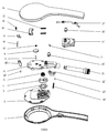
- the waterway device comprises a lower body 1 and an upper body 14.
- the upper and the lower body are respectively disposed with an upper handle and a lower handle, a shaft 21 having inlet function is disposed between the upper handle and the lower handle.
- a cover plate component 2 is embedded in the main body of the lower body 14, the rear side of the cover plate component 2 is disposed with an inlet ring 2-1, the inlet ring 2-1 is disposed with a plurality of inlet holes 2-2 annularly arranged, each inlet hole 2-2 is disposed with a special-shaped ring 3 for sealing, the sealing rings 3 are fixedly connected to form an annular structure; the front side of the cover plate component 2 is disposed with a plurality of outlet holes 2-3, which are divided to different outlet function sets, different inlet hole 2-2 (of different combination of the inlet holes) corresponds to different set of outlet holes 2-3 so as to form different outlet function. There are 2-4 outlet functions as needed, or more than 4.
- a water diversion plate 4 is disposed in the inlet ring 2-1 above the inlet holes 2-2, a pair of water diversion holes 4-1 are disposed at the water diversion plate symmetrically. When the water diversion plate rotates, the water diversion holes 4-1 are corresponding to different inlet holes 2-2 or the combination to switch the outlet functions.
- the center of the water diversion plate 4 is disposed with a non-circle plate shaft hole 4-2, in this embodiment, the section of which is semi-circle, to rotate the water diversion plate 4.
- Other shapes are available in other embodiments, such as triangle, rectangle and other non-circle shape.
- a fixing seat 6 is disposed above the water diversion plate, a taper spring 5 is disposed between the fixing seat 6 and the water diversion plate 4, the taper spring 5 is used to press the water diversion plate and to provide preload compensation to the sealing ring when in low water pressure.
- the fixing seat 6 comprises a main body 6-1, an extending section 6-2 and a rear section 6-3 from left to right, the right end of the rear section 6-3 is disposed with an inlet, which is connected to the outlet of the shaft 21.
- the bottom of the main body 6-1 is disposed with an outlet chamber 6-13.
- Four corners of the main body 6-1 are respectively disposed with a screw hole 6-4, the center of the main body 6-1 is disposed with a central through hole 6-5, on the upper surface of the main body 6-1, a stop pawl fixing seat 6-6 is disposed between the central through hole 6-5 and the screw hole 6-4 at the left upper corner.
- Two left-right sliding strips 6-7 are disposed parallel between the right upper and the right lower screw holes 6-4.
- the bottom portion of the extending section 6-2 is disposed with a pendulum fixing column 6-12, which is disposed with a pendulum fixing shaft hole.
- a left-right elongated through hole 6-8 is disposed in the extending section 6-2, the left end of the elongated through hole 6-8 is disposed with an elongated guide groove 6-9.
- the transition area of the extending section 6-2 and the rear section 6-3 is disposed with a press button fixing column 6-10, which is disposed with a press button fixing shaft hole 6-11.
- the waterway switch device comprises a ratchet wheel 9, the water diversion plate, a transmission mechanism and a driving mechanism, the water diversion plate has been described above.
- the ratchet wheel 9 is assembled to the center of the upper surface of the fixing seat 6, a synchronous shaft 8 is disposed between the ratchet wheel 9 and the water diversion plate 4, so that the ratchet wheel 9 and the water diversion plate 4 rotate synchronously.
- Two ends of the synchronous shaft 8 are non-circle shape that they are respectively inserted to the non-circle shaft hole of the ratchet wheel 9 and the water diversion plate 4.
- the transmission mechanism comprises a transmission element 13 and a transmission rack 16, the later one is generally cuboid, the central portion of the transmission rack 16 is concaved inwardly with a sliding chamber 16-1, the left and right side of the sliding chamber 16-1 are respectively disposed with a transmission element fixing hole 16-2, the transmission element 13 is assembled to the sliding chamber 16-1 by the transmission element fixing shaft 18.
- the left and right end of the transmission rack 16 are respectively protruding to one side with a spring fixing column 16-3, which is disposed inside with a spring chamber 16-4 and a first and a second reset spring 12.
- the transmission element 13 comprises a pivot portion 13-1 and a transmission portion 13-3, the pivot portion 13-1 is disposed with a shaft hole 13-2.
- the transmission element 13 is fixed into the sliding chamber 16-1 of the transmission rack 16 by the transmission element fixing shaft 18, the transmission element 13 can slide left and right along the transmission element fixing shaft 18 in the sliding chamber 16-1.
- a third reset spring 15 is sleeved on the transmission element fixing shaft 18 between the transmission element 13 and the inner side wall of the transmission rack.
- the driving mechanism comprises a press button 22, a pendulum 19 and a sliding block 17, the sliding block 17 is assembled to the guide groove 6-9 to slide along the guide groove 6-9 and limited.
- One end of the pendulum is pivoted to the pendulum fixing column 6-12 at the bottom of the fixing seat, the other end is a free end passing through the elongated through hole 6-8, one side surface of the free end abuts against the side surface of the sliding block 17;
- one end of the press button 22 is fixed to the press button fixing column 6-10 at the bottom of the fixing seat, the other end abuts against the other side surface of the free end of the pendulum.
- the waterway switch device further comprises a reset rack 11, which is generally rectangle, four corners are respectively disposed with screw hole 11-1 corresponding to the screw hole 6-4 of the fixing seat 6, the bottom portion is disposed with a receiving chamber 11-2, the lower side of the receiving chamber 11-2 is disposed with an opening 11-5, the left and right side of the central portion are disposed with a spring flapper 11-3, the lower portion of the spring flapper 11-3 is disposed with a limit portion 11-4, the transmission rack 16 enters the opening 11-5 and slides up and down along the limit portion 11-4.
- a reset rack 11 which is generally rectangle, four corners are respectively disposed with screw hole 11-1 corresponding to the screw hole 6-4 of the fixing seat 6, the bottom portion is disposed with a receiving chamber 11-2, the lower side of the receiving chamber 11-2 is disposed with an opening 11-5, the left and right side of the central portion are disposed with a spring flapper 11-3, the lower portion of the spring flapper 11-3 is disposed with a limit portion 11-4, the transmission rack 16 enters the
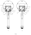
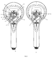
- the present invention is used as described hereafter, referring to FIG.2 and FIG.3 :
- the sliding block 17 pushes the transmission rack 16 to move up, so that the end of the transmission element 13 in the transmission rack 16 is contacted with the ratchet of the ratchet wheel to push the ratchet wheel to rotate in the counter-clockwise direction, during this proceed, the transmission element 13 slides to the right in the transmission rack 16, the third reset spring 15 is compressed; during the transmission rack 1 moving up, as the spring flapper 11-3 limits, the first and second reset springs 12 are compressed as well;
- the ratchet wheel 9 rotates to drive the water diversion plate 4 to rotate synchronously, the water diversion hole 4-1 of the water diversion plate 4 changes its position to align with other inlet hole 2-2 or the combination to achieve the switch of the outlet function.
- the stop pawl 7 abuts against the ratchet wheel to prevent the ratchet wheel from rotating reversely.
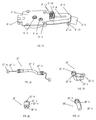
- the driving mechanism of this embodiment comprises a press button 22', two wire clasps 25', a steel wire unit 27' and the driving rod 28'.
- the wire clasp 25' comprises a fixing cover 25'-1 in the central, two sides of the fixing cover 25'-1 are disposed respectively with an extending portion 25'-2, each of which is disposed with a screw hole 25'-3, the lower surface of the fixing cover 25'-1 is disposed with a groove 25'-4 with section shape semi-circle.
- One of the wire clasps is fixed to the fixing seat 6', the other one is fixed to the reset rack 11.
- the pull rod 28' comprises a fixing end 28'-1 and a connecting end 28'-2, the fixing end 28'-1 is fixed to the pull rod fixing portion 6'-14 of the fixing seat 6' by the pull rod fixing shaft 29'.
- the connecting end 28'-2 is disposed with a still wire opening 28'-3.
- the press button 22' comprises a button cap 22'-1, one end of the bottom of which is disposed with a pivot portion 22'-2, the other end (free end) is disposed with a connecting portion 22'-3, the connecting portion 22'-3 is disposed with a wire groove 22'-4.
- the steel wire unit comprises a steel wire 27'-1
- the central section of the steel wire 27'-1 is disposed with a sleeve 27'-2
- two ends of the sleeve are respectively disposed with a fixing portion 27'-3
- one of the fixing portion 27'-3 is locked between the groove of the wire clasp of the fixing seat 6' and the steel wire fixing groove
- the other fixing portion 27'-3 is locked in the steel wire fixing groove 11'-6 of the reset rack 11.
- Two ends of the steel wire 27'-1 are respectively disposed with a limit column 27'-4, one is locked to the rear side of the wire groove 22'-4 of the press button 22', the other one is locked to the connecting end 28'-2 of the pull rod.
- the waterway switch device further comprises a reset rack 11', which is generally square shaped, four corners respectively disposed with a screw fixing hole 11'-1 corresponding to the screw fixing hole 6-4 of the fixing seat 6, the bottom portion is disposed with an accommodating chamber 11'-2, the lower portion of the accommodating chamber is disposed with an opening 11'-5, the left and right sides of the center portion are respectively disposed with a spring flapper 11'-3, the lower portion of the spring flapper 11'-3 is disposed with a limit portion 11'-4, the transmission rack 16 enters from the opening 11'-5 and slides up and down along the limit portion 11'-4.
- the top surface of the reset rack 11' is disposed with two wire clasp fixing columns11'-7 a steel wire fixing groove 11'-6 is disposed between the two wire clasp fixing columns.
- the pull rod 28' drives the transmission rack 16 contacted with the pull rod 28' to move downwardly.
- the transmission portion 11-3 at the end of the transmission element 13 in the transmission rack 16 is contacted with the ratchet of the ratchet wheel 9, the transmission portion 13-3 drives the ratchet wheel to rotate in the counter-clockwise direction, during this proceed, the transmission element 13 slides to the left in the transmission rack 16, the reset spring 15 is compressed; during the transmission rack 1 moving down, as the spring flapper 11-3 limits, two reset springs 12 are compressed as well;
- the ratchet wheel 9 rotates to drive the water diversion plate 4 to rotate synchronously, the water diversion hole 4 of the water diversion plate 4 changes its position to align with other inlet hole 2 or the combination to achieve the switch of the outlet function.
- the stop pawl 7 abuts against the ratchet wheel to prevent the ratchet wheel from rotating reversely.
- a switchable shower head which comprises a waterway device and a waterway switch device
- the waterway device comprises at least two outlet functions
- the waterway switch device comprises: a water diversion plate disposed in the waterway, when rotating the water diversion plate, the outlet is switched to different outlet functions; a ratchet wheel, which is coaxially connected to the water diversion plate; a transmission rack, which is disposed to the waterway device and is capable of moving away or closing to the ratchet wheel, the transmission rack is reset by two or more than two elastic elements; a transmission element, which is slidably assembled to the transmission rack and is capable of abutting against the ratchet of the ratchet wheel to move the ratchet wheel to rotate, an angle is formed between the sliding direction of the transmission element and the sliding direction of the transmission rack; and a driving mechanism, the driving mechanism comprises a press button and a driving means assembled between the press button and the transmission rack.
- the present invention is not limited, for example, the limit rack 11 can be integrated to the upper body 14 or the fixing rack, the receiving chamber of the transmission rack 16 can be a sliding groove, although the present invention has been described with reference to the preferred embodiments thereof for carrying out the patent for invention, it is apparent to those skilled in the art that a variety of modifications and changes may be made without departing from the scope of the patent for invention which is intended to be defined by the appended claims.
Landscapes
- Mechanically-Actuated Valves (AREA)
- Nozzles (AREA)
Applications Claiming Priority (1)
| Application Number | Priority Date | Filing Date | Title |
|---|---|---|---|
| CN201510647828.0A CN105478251B (zh) | 2015-10-09 | 2015-10-09 | 按压切换花洒 |
Publications (2)
| Publication Number | Publication Date |
|---|---|
| EP3153236A1 true EP3153236A1 (de) | 2017-04-12 |
| EP3153236B1 EP3153236B1 (de) | 2019-03-06 |
Family
ID=55665731
Family Applications (1)
| Application Number | Title | Priority Date | Filing Date |
|---|---|---|---|
| EP16001380.1A Not-in-force EP3153236B1 (de) | 2015-10-09 | 2016-06-20 | Schaltbarer duschkopf |
Country Status (3)
| Country | Link |
|---|---|
| US (1) | US10427174B2 (de) |
| EP (1) | EP3153236B1 (de) |
| CN (1) | CN105478251B (de) |
Cited By (3)
| Publication number | Priority date | Publication date | Assignee | Title |
|---|---|---|---|---|
| CN112843860A (zh) * | 2020-12-23 | 2021-05-28 | 沧州华润化工有限公司 | 一种环保节能的镀锌板光整液混合喷淋系统 |
| CN113273913A (zh) * | 2021-04-06 | 2021-08-20 | 张熙彤 | 一种节水淋浴喷头 |
| CN115443965A (zh) * | 2022-10-25 | 2022-12-09 | 庞成才 | 一种林业病虫害防治用悬挂式诱虫灭杀装置 |
Families Citing this family (34)
| Publication number | Priority date | Publication date | Assignee | Title |
|---|---|---|---|---|
| CN106622705B (zh) * | 2015-11-02 | 2019-02-15 | 厦门松霖科技股份有限公司 | 一种拨钮循环切换止水花洒 |
| CN106000689B (zh) * | 2016-07-28 | 2018-12-25 | 厦门建霖健康家居股份有限公司 | 双按钮花洒及其工作方法 |
| CN107433232A (zh) * | 2016-08-29 | 2017-12-05 | 厦门倍杰特科技股份公司 | 一种按钮切换机构及采用该切换机构的花洒 |
| CN107269884B (zh) * | 2017-06-27 | 2023-05-30 | 开平市汉顺洁具实业有限公司 | 一种具有复位功能的出水结构及出水结构的拉出头 |
| CN107159476B (zh) * | 2017-07-10 | 2023-03-31 | 恺霖卫浴科技(厦门)有限公司 | 一种通过按键切换出水状态的手持花洒 |
| DE102017216491A1 (de) | 2017-09-18 | 2019-03-21 | Hansgrohe Se | Fluidumstellvorrichtung und Sanitärbrause |
| US10413916B1 (en) | 2018-02-23 | 2019-09-17 | Robert W. Bruce | Shower head |
| CN108273679B (zh) * | 2018-03-19 | 2024-08-06 | 厦门松霖科技股份有限公司 | 薄型花洒及水路切换装置 |
| CN108380432A (zh) * | 2018-05-29 | 2018-08-10 | 泉州尚美生态园林工程有限公司 | 一种新型园林施工设备 |
| CN108476940A (zh) * | 2018-05-29 | 2018-09-04 | 泉州尚美生态园林工程有限公司 | 一种新型园林施工装置 |
| CN108476939A (zh) * | 2018-05-29 | 2018-09-04 | 福建省盛荣生态花卉研究院有限责任公司 | 一种园林施工装置 |
| CN108533824A (zh) * | 2018-05-29 | 2018-09-14 | 广州立杏科技有限公司 | 一种高效净化水龙头 |
| CN108476938A (zh) * | 2018-05-29 | 2018-09-04 | 泉州尚美生态园林工程有限公司 | 一种园林施工设备 |
| CN108889489B (zh) * | 2018-06-22 | 2023-07-18 | 厦门英仕卫浴有限公司 | 一种应用于节能淋浴龙头的人性化装置 |
| CN108772214A (zh) | 2018-07-31 | 2018-11-09 | 沛乐迪(厦门)卫浴有限公司 | 一种按钮切换花洒结构 |
| US10722906B2 (en) * | 2018-09-19 | 2020-07-28 | Purity (Xiamen) Sanitary Ware Co., Ltd. | Push-button switching shower head structure |
| CN109746133B (zh) * | 2018-12-12 | 2024-06-18 | 厦门松霖科技股份有限公司 | 一种出水装置及用于出水装置的驱动机构 |
| US10946394B2 (en) * | 2018-12-20 | 2021-03-16 | Purity (Xiamen) Sanitary Ware Co., Ltd. | Shower head water-saving switching structure and shower head |
| CN109701764A (zh) * | 2018-12-27 | 2019-05-03 | 厦门倍杰特科技股份公司 | 一种可左右摇动切换水花的花洒 |
| GB2584080B (en) * | 2019-05-13 | 2021-05-19 | Kohler Mira Ltd | Control mechanism |
| US11813622B2 (en) | 2019-05-29 | 2023-11-14 | Water Pik, Inc. | Showerhead with inline engine porting |
| CN112246457B (zh) * | 2020-09-24 | 2021-11-05 | 厦门欧圣斯卫浴有限公司 | 一种带有推钮的花洒 |
| CN213468264U (zh) * | 2020-09-24 | 2021-06-18 | 福建欣宇卫浴科技股份有限公司 | 侧面切换手柄自动回位花洒 |
| CN113117912B (zh) * | 2021-05-19 | 2022-08-05 | 厦门欧圣斯卫浴有限公司 | 一种多功能按钮切换的花洒 |
| CN113304900B (zh) * | 2021-06-18 | 2022-06-07 | 厦门欧圣斯卫浴有限公司 | 一种切换花洒 |
| CN113814078B (zh) * | 2021-07-24 | 2025-07-08 | 厦门倍杰特科技有限公司 | 一种水路切换结构及花洒 |
| US12539521B2 (en) | 2022-02-25 | 2026-02-03 | Delta Faucet Company | Linear diverter for hand shower |
| CN114700191B (zh) * | 2022-04-06 | 2024-07-19 | 厦门市得尔美卫浴有限公司 | 一种水力平衡的按键止水花洒 |
| CN217774471U (zh) * | 2022-06-22 | 2022-11-11 | 厦门广盛弘科技有限公司 | 一种花洒的侧按切换出水结构 |
| CN115104988B (zh) * | 2022-06-30 | 2026-01-13 | 宁波方太厨具有限公司 | 一种喷淋臂及具有该喷淋臂的洗碗机 |
| CN116528493B (zh) * | 2023-07-04 | 2023-11-24 | 捷成微系统(惠州)股份有限公司 | 一种pcb线路板的加工设备及加工方法 |
| CN221245646U (zh) * | 2023-10-12 | 2024-07-02 | 福建欣宇卫浴科技股份有限公司 | 一种花洒结构及淋浴装置 |
| CN117483127A (zh) | 2023-11-30 | 2024-02-02 | 福建欣宇卫浴科技股份有限公司 | 一种花洒 |
| CN120714425B (zh) * | 2025-09-01 | 2025-11-11 | 义县汇华化工有限公司 | 一种废气处理喷淋洗涤塔及使用方法 |
Citations (4)
| Publication number | Priority date | Publication date | Assignee | Title |
|---|---|---|---|---|
| US6622945B1 (en) * | 2003-02-27 | 2003-09-23 | James Wu | Shower head structure |
| EP1577016A1 (de) * | 2004-03-17 | 2005-09-21 | Fabrizio Nobili | Brausekopf mit kontinuierlicher Waaserstrahlsteuerung und Umschaltvorrichtung dafür |
| CN203750720U (zh) * | 2014-04-11 | 2014-08-06 | 九牧厨卫股份有限公司 | 花洒切换出水机构 |
| CN204544502U (zh) * | 2015-02-04 | 2015-08-12 | 厦门松霖科技有限公司 | 多功能花洒 |
Family Cites Families (14)
| Publication number | Priority date | Publication date | Assignee | Title |
|---|---|---|---|---|
| US3568716A (en) * | 1969-03-04 | 1971-03-09 | R & H Molding Inc | Turbine driven pulsating device |
| US4068801A (en) * | 1976-04-19 | 1978-01-17 | Alson's Corporation | Pulsating jet spray head |
| US3998390A (en) * | 1976-05-04 | 1976-12-21 | Associated Mills, Inc. | Selectable multiple-nozzle showerhead |
| US4043511A (en) * | 1976-07-14 | 1977-08-23 | Sanyei Corporation | Shower head |
| US5215258A (en) * | 1991-08-06 | 1993-06-01 | Pollenex Corporation | Active shower head |
| US5433384A (en) * | 1994-06-24 | 1995-07-18 | Jing Mei Industrial Limited | Push button controlled multifunction shower head |
| WO2011085667A1 (zh) * | 2010-01-15 | 2011-07-21 | 厦门松霖科技有限公司 | 单点触碰花洒 |
| US8366025B2 (en) * | 2011-04-15 | 2013-02-05 | Globe Union Industrial Corp. | Shower head |
| CN202398444U (zh) * | 2011-10-10 | 2012-08-29 | 厦门凯美欧卫浴科技有限公司 | 一种自动切换功能的花洒 |
| CN203459184U (zh) * | 2013-09-27 | 2014-03-05 | 余姚市心雨洁具有限公司 | 一种推钮式切换水花洒 |
| CN203750723U (zh) * | 2014-01-15 | 2014-08-06 | 东莞市适意洁具有限公司 | 一种单向双功能手提式花洒 |
| CN203842734U (zh) * | 2014-04-17 | 2014-09-24 | 九牧厨卫股份有限公司 | 一种按钮切换水路的花洒 |
| CN104923420B (zh) * | 2015-06-26 | 2017-10-27 | 厦门英仕卫浴有限公司 | 一种出水切换装置 |
| CN205128222U (zh) * | 2015-10-09 | 2016-04-06 | 厦门倍杰特科技有限公司 | 一种按压切换花洒 |
-
2015
- 2015-10-09 CN CN201510647828.0A patent/CN105478251B/zh not_active Expired - Fee Related
-
2016
- 2016-06-20 EP EP16001380.1A patent/EP3153236B1/de not_active Not-in-force
- 2016-09-16 US US15/268,009 patent/US10427174B2/en not_active Expired - Fee Related
Patent Citations (4)
| Publication number | Priority date | Publication date | Assignee | Title |
|---|---|---|---|---|
| US6622945B1 (en) * | 2003-02-27 | 2003-09-23 | James Wu | Shower head structure |
| EP1577016A1 (de) * | 2004-03-17 | 2005-09-21 | Fabrizio Nobili | Brausekopf mit kontinuierlicher Waaserstrahlsteuerung und Umschaltvorrichtung dafür |
| CN203750720U (zh) * | 2014-04-11 | 2014-08-06 | 九牧厨卫股份有限公司 | 花洒切换出水机构 |
| CN204544502U (zh) * | 2015-02-04 | 2015-08-12 | 厦门松霖科技有限公司 | 多功能花洒 |
Cited By (3)
| Publication number | Priority date | Publication date | Assignee | Title |
|---|---|---|---|---|
| CN112843860A (zh) * | 2020-12-23 | 2021-05-28 | 沧州华润化工有限公司 | 一种环保节能的镀锌板光整液混合喷淋系统 |
| CN113273913A (zh) * | 2021-04-06 | 2021-08-20 | 张熙彤 | 一种节水淋浴喷头 |
| CN115443965A (zh) * | 2022-10-25 | 2022-12-09 | 庞成才 | 一种林业病虫害防治用悬挂式诱虫灭杀装置 |
Also Published As
| Publication number | Publication date |
|---|---|
| CN105478251B (zh) | 2018-05-25 |
| US10427174B2 (en) | 2019-10-01 |
| CN105478251A (zh) | 2016-04-13 |
| US20170100728A1 (en) | 2017-04-13 |
| EP3153236B1 (de) | 2019-03-06 |
Similar Documents
| Publication | Publication Date | Title |
|---|---|---|
| EP3153236B1 (de) | Schaltbarer duschkopf | |
| US9829116B2 (en) | Switch valve and shower head applied with the switch valve | |
| US9656279B2 (en) | Top spraying shower head with reset function | |
| EP3053655A1 (de) | Multifunktionaler duschkopf | |
| US6789751B1 (en) | Collapsible handle for a shower head | |
| US9939071B2 (en) | Waterway switch and on-off mechanism | |
| US9587383B2 (en) | Pilot valve switch mechanism and a combined shower applied with the pilot valve switch mechanism | |
| US9895702B2 (en) | Single pushbutton device for switching to output water with multiple spray patterns | |
| US10946394B2 (en) | Shower head water-saving switching structure and shower head | |
| US9573143B2 (en) | Side spraying shower head | |
| US9615697B2 (en) | Combined pilot valve mechanism and a shower system applied with the combined pilot valve mechanism | |
| EP3108964A1 (de) | Doppelfunktion tastschalterbrausekopf | |
| US10618064B2 (en) | Multi-functional shower | |
| US7331567B2 (en) | Coupling device for two connecting poles | |
| CN108772214A (zh) | 一种按钮切换花洒结构 | |
| US20160263597A1 (en) | Combined shower with gravity switch mechanism | |
| WO2018120279A1 (zh) | 一种按钮切换出水功能的手持花洒 | |
| US10066374B2 (en) | Single button, cyclic shower head switch | |
| CN105478252B (zh) | 按压切换结构花洒 | |
| USD884837S1 (en) | Faucet handle | |
| US6827186B1 (en) | Pull rod control mechanism of luggage | |
| CN205128222U (zh) | 一种按压切换花洒 | |
| CN209789383U (zh) | 一种为盲人设计用的杯子 | |
| CN210300826U (zh) | 一种感应开关 | |
| AU2003216931A1 (en) | Dual-head micro vacuum pump |
Legal Events
| Date | Code | Title | Description |
|---|---|---|---|
| PUAI | Public reference made under article 153(3) epc to a published international application that has entered the european phase |
Free format text: ORIGINAL CODE: 0009012 |
|
| STAA | Information on the status of an ep patent application or granted ep patent |
Free format text: STATUS: THE APPLICATION HAS BEEN PUBLISHED |
|
| AK | Designated contracting states |
Kind code of ref document: A1 Designated state(s): AL AT BE BG CH CY CZ DE DK EE ES FI FR GB GR HR HU IE IS IT LI LT LU LV MC MK MT NL NO PL PT RO RS SE SI SK SM TR |
|
| AX | Request for extension of the european patent |
Extension state: BA ME |
|
| STAA | Information on the status of an ep patent application or granted ep patent |
Free format text: STATUS: REQUEST FOR EXAMINATION WAS MADE |
|
| RIN1 | Information on inventor provided before grant (corrected) |
Inventor name: LIN, CHAOJIAN Inventor name: HE, JIANBO Inventor name: GUO, MENGSHI Inventor name: GONG, BINHUA |
|
| RAP1 | Party data changed (applicant data changed or rights of an application transferred) |
Owner name: BESTTER (XIAMEN) TECHNOLOGY INC. |
|
| 17P | Request for examination filed |
Effective date: 20171012 |
|
| RBV | Designated contracting states (corrected) |
Designated state(s): AL AT BE BG CH CY CZ DE DK EE ES FI FR GB GR HR HU IE IS IT LI LT LU LV MC MK MT NL NO PL PT RO RS SE SI SK SM TR |
|
| GRAP | Despatch of communication of intention to grant a patent |
Free format text: ORIGINAL CODE: EPIDOSNIGR1 |
|
| STAA | Information on the status of an ep patent application or granted ep patent |
Free format text: STATUS: GRANT OF PATENT IS INTENDED |
|
| INTG | Intention to grant announced |
Effective date: 20180913 |
|
| GRAS | Grant fee paid |
Free format text: ORIGINAL CODE: EPIDOSNIGR3 |
|
| GRAA | (expected) grant |
Free format text: ORIGINAL CODE: 0009210 |
|
| STAA | Information on the status of an ep patent application or granted ep patent |
Free format text: STATUS: THE PATENT HAS BEEN GRANTED |
|
| AK | Designated contracting states |
Kind code of ref document: B1 Designated state(s): AL AT BE BG CH CY CZ DE DK EE ES FI FR GB GR HR HU IE IS IT LI LT LU LV MC MK MT NL NO PL PT RO RS SE SI SK SM TR |
|
| REG | Reference to a national code |
Ref country code: GB Ref legal event code: FG4D |
|
| REG | Reference to a national code |
Ref country code: CH Ref legal event code: EP Ref country code: AT Ref legal event code: REF Ref document number: 1103831 Country of ref document: AT Kind code of ref document: T Effective date: 20190315 |
|
| REG | Reference to a national code |
Ref country code: DE Ref legal event code: R096 Ref document number: 602016010530 Country of ref document: DE |
|
| REG | Reference to a national code |
Ref country code: IE Ref legal event code: FG4D |
|
| REG | Reference to a national code |
Ref country code: NL Ref legal event code: MP Effective date: 20190306 |
|
| REG | Reference to a national code |
Ref country code: LT Ref legal event code: MG4D |
|
| PG25 | Lapsed in a contracting state [announced via postgrant information from national office to epo] |
Ref country code: FI Free format text: LAPSE BECAUSE OF FAILURE TO SUBMIT A TRANSLATION OF THE DESCRIPTION OR TO PAY THE FEE WITHIN THE PRESCRIBED TIME-LIMIT Effective date: 20190306 Ref country code: LT Free format text: LAPSE BECAUSE OF FAILURE TO SUBMIT A TRANSLATION OF THE DESCRIPTION OR TO PAY THE FEE WITHIN THE PRESCRIBED TIME-LIMIT Effective date: 20190306 Ref country code: SE Free format text: LAPSE BECAUSE OF FAILURE TO SUBMIT A TRANSLATION OF THE DESCRIPTION OR TO PAY THE FEE WITHIN THE PRESCRIBED TIME-LIMIT Effective date: 20190306 Ref country code: NO Free format text: LAPSE BECAUSE OF FAILURE TO SUBMIT A TRANSLATION OF THE DESCRIPTION OR TO PAY THE FEE WITHIN THE PRESCRIBED TIME-LIMIT Effective date: 20190606 |
|
| PG25 | Lapsed in a contracting state [announced via postgrant information from national office to epo] |
Ref country code: HR Free format text: LAPSE BECAUSE OF FAILURE TO SUBMIT A TRANSLATION OF THE DESCRIPTION OR TO PAY THE FEE WITHIN THE PRESCRIBED TIME-LIMIT Effective date: 20190306 Ref country code: LV Free format text: LAPSE BECAUSE OF FAILURE TO SUBMIT A TRANSLATION OF THE DESCRIPTION OR TO PAY THE FEE WITHIN THE PRESCRIBED TIME-LIMIT Effective date: 20190306 Ref country code: GR Free format text: LAPSE BECAUSE OF FAILURE TO SUBMIT A TRANSLATION OF THE DESCRIPTION OR TO PAY THE FEE WITHIN THE PRESCRIBED TIME-LIMIT Effective date: 20190607 Ref country code: BG Free format text: LAPSE BECAUSE OF FAILURE TO SUBMIT A TRANSLATION OF THE DESCRIPTION OR TO PAY THE FEE WITHIN THE PRESCRIBED TIME-LIMIT Effective date: 20190606 Ref country code: RS Free format text: LAPSE BECAUSE OF FAILURE TO SUBMIT A TRANSLATION OF THE DESCRIPTION OR TO PAY THE FEE WITHIN THE PRESCRIBED TIME-LIMIT Effective date: 20190306 Ref country code: NL Free format text: LAPSE BECAUSE OF FAILURE TO SUBMIT A TRANSLATION OF THE DESCRIPTION OR TO PAY THE FEE WITHIN THE PRESCRIBED TIME-LIMIT Effective date: 20190306 |
|
| REG | Reference to a national code |
Ref country code: AT Ref legal event code: MK05 Ref document number: 1103831 Country of ref document: AT Kind code of ref document: T Effective date: 20190306 |
|
| PG25 | Lapsed in a contracting state [announced via postgrant information from national office to epo] |
Ref country code: PT Free format text: LAPSE BECAUSE OF FAILURE TO SUBMIT A TRANSLATION OF THE DESCRIPTION OR TO PAY THE FEE WITHIN THE PRESCRIBED TIME-LIMIT Effective date: 20190706 Ref country code: AL Free format text: LAPSE BECAUSE OF FAILURE TO SUBMIT A TRANSLATION OF THE DESCRIPTION OR TO PAY THE FEE WITHIN THE PRESCRIBED TIME-LIMIT Effective date: 20190306 Ref country code: CZ Free format text: LAPSE BECAUSE OF FAILURE TO SUBMIT A TRANSLATION OF THE DESCRIPTION OR TO PAY THE FEE WITHIN THE PRESCRIBED TIME-LIMIT Effective date: 20190306 Ref country code: ES Free format text: LAPSE BECAUSE OF FAILURE TO SUBMIT A TRANSLATION OF THE DESCRIPTION OR TO PAY THE FEE WITHIN THE PRESCRIBED TIME-LIMIT Effective date: 20190306 Ref country code: SK Free format text: LAPSE BECAUSE OF FAILURE TO SUBMIT A TRANSLATION OF THE DESCRIPTION OR TO PAY THE FEE WITHIN THE PRESCRIBED TIME-LIMIT Effective date: 20190306 Ref country code: RO Free format text: LAPSE BECAUSE OF FAILURE TO SUBMIT A TRANSLATION OF THE DESCRIPTION OR TO PAY THE FEE WITHIN THE PRESCRIBED TIME-LIMIT Effective date: 20190306 Ref country code: IT Free format text: LAPSE BECAUSE OF FAILURE TO SUBMIT A TRANSLATION OF THE DESCRIPTION OR TO PAY THE FEE WITHIN THE PRESCRIBED TIME-LIMIT Effective date: 20190306 Ref country code: EE Free format text: LAPSE BECAUSE OF FAILURE TO SUBMIT A TRANSLATION OF THE DESCRIPTION OR TO PAY THE FEE WITHIN THE PRESCRIBED TIME-LIMIT Effective date: 20190306 |
|
| PG25 | Lapsed in a contracting state [announced via postgrant information from national office to epo] |
Ref country code: PL Free format text: LAPSE BECAUSE OF FAILURE TO SUBMIT A TRANSLATION OF THE DESCRIPTION OR TO PAY THE FEE WITHIN THE PRESCRIBED TIME-LIMIT Effective date: 20190306 Ref country code: SM Free format text: LAPSE BECAUSE OF FAILURE TO SUBMIT A TRANSLATION OF THE DESCRIPTION OR TO PAY THE FEE WITHIN THE PRESCRIBED TIME-LIMIT Effective date: 20190306 |
|
| REG | Reference to a national code |
Ref country code: DE Ref legal event code: R097 Ref document number: 602016010530 Country of ref document: DE |
|
| PG25 | Lapsed in a contracting state [announced via postgrant information from national office to epo] |
Ref country code: IS Free format text: LAPSE BECAUSE OF FAILURE TO SUBMIT A TRANSLATION OF THE DESCRIPTION OR TO PAY THE FEE WITHIN THE PRESCRIBED TIME-LIMIT Effective date: 20190706 Ref country code: AT Free format text: LAPSE BECAUSE OF FAILURE TO SUBMIT A TRANSLATION OF THE DESCRIPTION OR TO PAY THE FEE WITHIN THE PRESCRIBED TIME-LIMIT Effective date: 20190306 |
|
| PLBE | No opposition filed within time limit |
Free format text: ORIGINAL CODE: 0009261 |
|
| STAA | Information on the status of an ep patent application or granted ep patent |
Free format text: STATUS: NO OPPOSITION FILED WITHIN TIME LIMIT |
|
| PG25 | Lapsed in a contracting state [announced via postgrant information from national office to epo] |
Ref country code: DK Free format text: LAPSE BECAUSE OF FAILURE TO SUBMIT A TRANSLATION OF THE DESCRIPTION OR TO PAY THE FEE WITHIN THE PRESCRIBED TIME-LIMIT Effective date: 20190306 Ref country code: MC Free format text: LAPSE BECAUSE OF FAILURE TO SUBMIT A TRANSLATION OF THE DESCRIPTION OR TO PAY THE FEE WITHIN THE PRESCRIBED TIME-LIMIT Effective date: 20190306 |
|
| REG | Reference to a national code |
Ref country code: CH Ref legal event code: PL |
|
| 26N | No opposition filed |
Effective date: 20191209 |
|
| PG25 | Lapsed in a contracting state [announced via postgrant information from national office to epo] |
Ref country code: SI Free format text: LAPSE BECAUSE OF FAILURE TO SUBMIT A TRANSLATION OF THE DESCRIPTION OR TO PAY THE FEE WITHIN THE PRESCRIBED TIME-LIMIT Effective date: 20190306 |
|
| REG | Reference to a national code |
Ref country code: BE Ref legal event code: MM Effective date: 20190630 |
|
| PG25 | Lapsed in a contracting state [announced via postgrant information from national office to epo] |
Ref country code: TR Free format text: LAPSE BECAUSE OF FAILURE TO SUBMIT A TRANSLATION OF THE DESCRIPTION OR TO PAY THE FEE WITHIN THE PRESCRIBED TIME-LIMIT Effective date: 20190306 |
|
| PG25 | Lapsed in a contracting state [announced via postgrant information from national office to epo] |
Ref country code: IE Free format text: LAPSE BECAUSE OF NON-PAYMENT OF DUE FEES Effective date: 20190620 |
|
| PG25 | Lapsed in a contracting state [announced via postgrant information from national office to epo] |
Ref country code: CH Free format text: LAPSE BECAUSE OF NON-PAYMENT OF DUE FEES Effective date: 20190630 Ref country code: BE Free format text: LAPSE BECAUSE OF NON-PAYMENT OF DUE FEES Effective date: 20190630 Ref country code: LI Free format text: LAPSE BECAUSE OF NON-PAYMENT OF DUE FEES Effective date: 20190630 Ref country code: LU Free format text: LAPSE BECAUSE OF NON-PAYMENT OF DUE FEES Effective date: 20190620 |
|
| PG25 | Lapsed in a contracting state [announced via postgrant information from national office to epo] |
Ref country code: FR Free format text: LAPSE BECAUSE OF NON-PAYMENT OF DUE FEES Effective date: 20190630 |
|
| PG25 | Lapsed in a contracting state [announced via postgrant information from national office to epo] |
Ref country code: CY Free format text: LAPSE BECAUSE OF FAILURE TO SUBMIT A TRANSLATION OF THE DESCRIPTION OR TO PAY THE FEE WITHIN THE PRESCRIBED TIME-LIMIT Effective date: 20190306 |
|
| PG25 | Lapsed in a contracting state [announced via postgrant information from national office to epo] |
Ref country code: HU Free format text: LAPSE BECAUSE OF FAILURE TO SUBMIT A TRANSLATION OF THE DESCRIPTION OR TO PAY THE FEE WITHIN THE PRESCRIBED TIME-LIMIT; INVALID AB INITIO Effective date: 20160620 Ref country code: MT Free format text: LAPSE BECAUSE OF FAILURE TO SUBMIT A TRANSLATION OF THE DESCRIPTION OR TO PAY THE FEE WITHIN THE PRESCRIBED TIME-LIMIT Effective date: 20190306 |
|
| PG25 | Lapsed in a contracting state [announced via postgrant information from national office to epo] |
Ref country code: MK Free format text: LAPSE BECAUSE OF FAILURE TO SUBMIT A TRANSLATION OF THE DESCRIPTION OR TO PAY THE FEE WITHIN THE PRESCRIBED TIME-LIMIT Effective date: 20190306 |
|
| PGFP | Annual fee paid to national office [announced via postgrant information from national office to epo] |
Ref country code: GB Payment date: 20220623 Year of fee payment: 7 Ref country code: DE Payment date: 20220630 Year of fee payment: 7 |
|
| REG | Reference to a national code |
Ref country code: DE Ref legal event code: R119 Ref document number: 602016010530 Country of ref document: DE |
|
| GBPC | Gb: european patent ceased through non-payment of renewal fee |
Effective date: 20230620 |
|
| PG25 | Lapsed in a contracting state [announced via postgrant information from national office to epo] |
Ref country code: DE Free format text: LAPSE BECAUSE OF NON-PAYMENT OF DUE FEES Effective date: 20240103 Ref country code: GB Free format text: LAPSE BECAUSE OF NON-PAYMENT OF DUE FEES Effective date: 20230620 |