EP3153320B1 - Appareil d'alimentation de liquide - Google Patents
Appareil d'alimentation de liquide Download PDFInfo
- Publication number
- EP3153320B1 EP3153320B1 EP16191131.8A EP16191131A EP3153320B1 EP 3153320 B1 EP3153320 B1 EP 3153320B1 EP 16191131 A EP16191131 A EP 16191131A EP 3153320 B1 EP3153320 B1 EP 3153320B1
- Authority
- EP
- European Patent Office
- Prior art keywords
- posture
- cartridge
- cover
- locking
- ink
- Prior art date
- Legal status (The legal status is an assumption and is not a legal conclusion. Google has not performed a legal analysis and makes no representation as to the accuracy of the status listed.)
- Active
Links
Images








Classifications
-
- B—PERFORMING OPERATIONS; TRANSPORTING
- B41—PRINTING; LINING MACHINES; TYPEWRITERS; STAMPS
- B41J—TYPEWRITERS; SELECTIVE PRINTING MECHANISMS, i.e. MECHANISMS PRINTING OTHERWISE THAN FROM A FORME; CORRECTION OF TYPOGRAPHICAL ERRORS
- B41J2/00—Typewriters or selective printing mechanisms characterised by the printing or marking process for which they are designed
- B41J2/005—Typewriters or selective printing mechanisms characterised by the printing or marking process for which they are designed characterised by bringing liquid or particles selectively into contact with a printing material
- B41J2/01—Ink jet
- B41J2/17—Ink jet characterised by ink handling
- B41J2/175—Ink supply systems ; Circuit parts therefor
- B41J2/17503—Ink cartridges
- B41J2/17506—Refilling of the cartridge
- B41J2/17509—Whilst mounted in the printer
-
- B—PERFORMING OPERATIONS; TRANSPORTING
- B41—PRINTING; LINING MACHINES; TYPEWRITERS; STAMPS
- B41J—TYPEWRITERS; SELECTIVE PRINTING MECHANISMS, i.e. MECHANISMS PRINTING OTHERWISE THAN FROM A FORME; CORRECTION OF TYPOGRAPHICAL ERRORS
- B41J2/00—Typewriters or selective printing mechanisms characterised by the printing or marking process for which they are designed
- B41J2/005—Typewriters or selective printing mechanisms characterised by the printing or marking process for which they are designed characterised by bringing liquid or particles selectively into contact with a printing material
- B41J2/01—Ink jet
- B41J2/17—Ink jet characterised by ink handling
- B41J2/175—Ink supply systems ; Circuit parts therefor
- B41J2/17503—Ink cartridges
-
- B—PERFORMING OPERATIONS; TRANSPORTING
- B41—PRINTING; LINING MACHINES; TYPEWRITERS; STAMPS
- B41J—TYPEWRITERS; SELECTIVE PRINTING MECHANISMS, i.e. MECHANISMS PRINTING OTHERWISE THAN FROM A FORME; CORRECTION OF TYPOGRAPHICAL ERRORS
- B41J2/00—Typewriters or selective printing mechanisms characterised by the printing or marking process for which they are designed
- B41J2/005—Typewriters or selective printing mechanisms characterised by the printing or marking process for which they are designed characterised by bringing liquid or particles selectively into contact with a printing material
- B41J2/01—Ink jet
- B41J2/17—Ink jet characterised by ink handling
- B41J2/175—Ink supply systems ; Circuit parts therefor
- B41J2/17503—Ink cartridges
- B41J2/17513—Inner structure
-
- B—PERFORMING OPERATIONS; TRANSPORTING
- B41—PRINTING; LINING MACHINES; TYPEWRITERS; STAMPS
- B41J—TYPEWRITERS; SELECTIVE PRINTING MECHANISMS, i.e. MECHANISMS PRINTING OTHERWISE THAN FROM A FORME; CORRECTION OF TYPOGRAPHICAL ERRORS
- B41J2/00—Typewriters or selective printing mechanisms characterised by the printing or marking process for which they are designed
- B41J2/005—Typewriters or selective printing mechanisms characterised by the printing or marking process for which they are designed characterised by bringing liquid or particles selectively into contact with a printing material
- B41J2/01—Ink jet
- B41J2/17—Ink jet characterised by ink handling
- B41J2/175—Ink supply systems ; Circuit parts therefor
- B41J2/17503—Ink cartridges
- B41J2/1752—Mounting within the printer
-
- B—PERFORMING OPERATIONS; TRANSPORTING
- B41—PRINTING; LINING MACHINES; TYPEWRITERS; STAMPS
- B41J—TYPEWRITERS; SELECTIVE PRINTING MECHANISMS, i.e. MECHANISMS PRINTING OTHERWISE THAN FROM A FORME; CORRECTION OF TYPOGRAPHICAL ERRORS
- B41J2/00—Typewriters or selective printing mechanisms characterised by the printing or marking process for which they are designed
- B41J2/005—Typewriters or selective printing mechanisms characterised by the printing or marking process for which they are designed characterised by bringing liquid or particles selectively into contact with a printing material
- B41J2/01—Ink jet
- B41J2/17—Ink jet characterised by ink handling
- B41J2/175—Ink supply systems ; Circuit parts therefor
- B41J2/17503—Ink cartridges
- B41J2/1752—Mounting within the printer
- B41J2/17523—Ink connection
-
- B—PERFORMING OPERATIONS; TRANSPORTING
- B41—PRINTING; LINING MACHINES; TYPEWRITERS; STAMPS
- B41J—TYPEWRITERS; SELECTIVE PRINTING MECHANISMS, i.e. MECHANISMS PRINTING OTHERWISE THAN FROM A FORME; CORRECTION OF TYPOGRAPHICAL ERRORS
- B41J2/00—Typewriters or selective printing mechanisms characterised by the printing or marking process for which they are designed
- B41J2/005—Typewriters or selective printing mechanisms characterised by the printing or marking process for which they are designed characterised by bringing liquid or particles selectively into contact with a printing material
- B41J2/01—Ink jet
- B41J2/17—Ink jet characterised by ink handling
- B41J2/175—Ink supply systems ; Circuit parts therefor
- B41J2/17503—Ink cartridges
- B41J2/17553—Outer structure
-
- B—PERFORMING OPERATIONS; TRANSPORTING
- B41—PRINTING; LINING MACHINES; TYPEWRITERS; STAMPS
- B41J—TYPEWRITERS; SELECTIVE PRINTING MECHANISMS, i.e. MECHANISMS PRINTING OTHERWISE THAN FROM A FORME; CORRECTION OF TYPOGRAPHICAL ERRORS
- B41J2/00—Typewriters or selective printing mechanisms characterised by the printing or marking process for which they are designed
- B41J2/005—Typewriters or selective printing mechanisms characterised by the printing or marking process for which they are designed characterised by bringing liquid or particles selectively into contact with a printing material
- B41J2/01—Ink jet
- B41J2/17—Ink jet characterised by ink handling
- B41J2/175—Ink supply systems ; Circuit parts therefor
- B41J2/17566—Ink level or ink residue control
-
- B—PERFORMING OPERATIONS; TRANSPORTING
- B41—PRINTING; LINING MACHINES; TYPEWRITERS; STAMPS
- B41J—TYPEWRITERS; SELECTIVE PRINTING MECHANISMS, i.e. MECHANISMS PRINTING OTHERWISE THAN FROM A FORME; CORRECTION OF TYPOGRAPHICAL ERRORS
- B41J2/00—Typewriters or selective printing mechanisms characterised by the printing or marking process for which they are designed
- B41J2/005—Typewriters or selective printing mechanisms characterised by the printing or marking process for which they are designed characterised by bringing liquid or particles selectively into contact with a printing material
- B41J2/01—Ink jet
- B41J2/17—Ink jet characterised by ink handling
- B41J2/175—Ink supply systems ; Circuit parts therefor
- B41J2/17566—Ink level or ink residue control
- B41J2002/17576—Ink level or ink residue control using a floater for ink level indication
Definitions
- the present invention relates to a liquid supply apparatus having a cartridge attaching portion to which a liquid cartridge is attachable, and a cover that opens and closes an opening of the cartridge attaching portion.
- An ink jet recording device in which an ink retained in an ink vessel is ejected from a nozzle to form an image on an image recording medium.
- An ink cartridge is detachably attached to the ink jet recording device so that the old cartridge can be replaced by a new cartridge each time the ink in the old ink cartridge is consumed up.
- Japanese Patent Application Publication No. 2002-508720 discloses an ink vessel 12 is detachable from and attachable to a printer 86.
- reference numerals mentioned herein are those described in the JP '720 publication.
- the ink vessel 12 is provided with an engagement mechanism 62.
- the ink vessel 12 can be subjected to accurate positioning in the printer 86 against biasing forces of springs 98, 108 as a result of engagement of the engagement mechanism 62 with an engaging mechanism 76 of the printer 86.
- Japanese Patent Application Publication No. 2005-74979 discloses an ink jet printer.
- reference numerals mentioned herein are those described in the JP '979 publication.
- a cover 57 In a state where an ink cartridge 22 is inserted to a predetermined position in a cartridge accommodating portion 59, a cover 57 can be closed without mechanical interference between a cartridge-side interference portion 44 and a cover-side interference portion 75.
- the cover 57 cannot be closed due to mechanical interference between the cartridge-side interference portion 44 and the cover-side interference portion 75.
- the ink vessel 12 cannot be moved outside of the printer 86 by the biasing forces of the springs 98, 108, unless the ink vessel 12 is pivotally moved in the printer 86 from a posture at which the engagement mechanism 62 and the engaging mechanism 76 are engaged with each other to a posture at which these engaging mechanisms 62 and 76 are not engaged with each other. Therefore, in a state where the ink vessel 12 has been subjected to positioning in the printer 86, the ink vessel 12 is desirably pivotally moved easily to the posture at which these engaging mechanisms 62 and 76 are not engaged with each other without mechanical interference with the printer 86.
- the ink vessel 12 may be accidentally released from the printer 86 due to application of impact or vibration in spite of the fact that the user does not intend to take out the ink vessel 12 out of the printer 86.
- US 2011/096127 A1 discloses a liquid supply apparatus according to the preamble of claim 1.
- Other apparatuses are known from US 2004/196333 A1 ; EP 2 070 706 A1 ; and EP 3 112 168 A1 .
- an object of the present invention to provide a liquid supply apparatus capable of enabling a user to recognize unlocked state of the liquid cartridge relative to a cartridge attaching portion through opening and closing operation of the cover, and also capable of preventing the liquid cartridge from being released or unlocked relative to the cartridge attaching portion from the locked state of the liquid cartridge in a state where the cover is closed.
- This object is achieved by the liquid supply apparatus having the features of claim 1.
- the present invention is further developed as defined in the dependent claims.
- the liquid supply apparatus comprises a liquid cartridge which is attachable into an attaching portion of the liquid supply apparatus by an insertion of the liquid cartridge in a first direction against a biasing force directed in a second direction opposite to the first direction.
- the liquid cartridge includes a liquid retaining chamber, a front surface, a rear surface, a side surface, a liquid supply portion, a locking surface, a recess, and a first portion.
- the front surface faces in the first direction in a state of the insertion.
- the rear surface is disposed opposite to the front surface.
- the liquid retaining chamber is interposed between the rear surface and the front surface.
- the side surface extends between the front surface and the rear surface.
- the liquid supply portion is provided at the front surface.
- the locking surface is provided at the side surface.
- the recess opens in the second direction.
- the first portion is accessible from an outside of the liquid cartridge in the first direction.
- the liquid supply apparatus includes the attaching portion having an opening through which the liquid cartridge is inserted into the attaching portion.
- the attaching portion includes a liquid supply tube, a locking portion, and a cover.
- the liquid supply tube is configured to be inserted into the liquid supply portion.
- the locking portion is configured to be abutted on the locking surface.
- the cover is pivotally movable between an open posture opening the opening and a closed posture closing the opening.
- the cover has a second portion and a protrusion protruding from the second portion.
- the liquid cartridge In a state where the liquid supply tube is inserted into the liquid supply portion, the liquid cartridge is pivotally movable in the attaching portion between a first posture and a second posture.
- the locking surface of the liquid cartridge in the first posture is in confrontation with and capable of abutting on the locking portion in the first direction and the second direction.
- the locking surface of the liquid cartridge in the second posture is not in confrontation with the locking portion in the first direction and the second direction.
- the liquid cartridge in the first posture is brought into a locked state where the liquid cartridge is locked relative to the attaching portion by abutment of the locking surface with the locking portion in the second direction against the biasing force.
- the protrusion of the cover in the closed posture is accommodated in the recess of the liquid cartridge in the locked state to prevent the liquid cartridge in the locked state from moving toward the second posture.
- the protrusion of the cover abuts on the first portion to move the liquid cartridge in the first direction until the locking surface is positioned further in the first direction relative to the locking portion while the cover holds the liquid cartridge by abutment of the protrusion and the first portion to prevent the liquid cartridge from changing its posture to the first posture.
- L1 is a distance between a rear end of the first portion and the second portion in the first direction in a state where the protrusion is in abutment with the first portion and the locking surface is positioned at a stroke end position.
- the locking surface moves past the locking portion in the first direction to reach the stroke end position of the locking surface during the pivotal movement of the cover from the open posture toward the closed posture.
- L2 is a distance between the locking surface and a front end of the locking portion in the first direction in the state where the protrusion is in abutment with the first portion and the locking surface is positioned at the stroke end position.
- L4 is a distance between the rear end of the first portion and the second portion in the first direction in a state where the protrusion of the cover in the closed posture is accommodated in the recess of the liquid cartridge in the locked state.
- the protrusion has an tip end on which an engagement portion is provided.
- the tip end is configured to abut on the first portion.
- the engagement portion is configured to engage the first portion.
- the first portion in abutment with the tip end is in engagement with the engagement portion.
- the engagement portion in engagement with the first portion prevents the liquid cartridge from changing its posture toward the first posture.
- the engagement portion has a guide surface configured to guide the first portion.
- the guide surface of the engagement portion in abutment with the first portion guides the first portion such that the liquid cartridge changes its posture toward the second posture.
- the side surface of the liquid cartridge is provided with a manipulation surface and a sub-side surface.
- the manipulation surface is disposed at a position closer to the rear surface than the locking surface to the rear surface.
- the sub-side surface overlaps with the manipulation surface when viewed in a direction perpendicular to the side surface.
- the recess is defined between the manipulation surface and the sub-side surface.
- the liquid cartridge is provided with a rib extending from the sub-side surface to a back surface of the manipulation surface in the recess wherein the back surface and the manipulation surface are provided at the first portion, the back surface being opposite to the manipulation surface in the direction perpendicular to the side surface.
- a plurality of cartridges are attachable to the attaching portion.
- the plurality of liquid cartridges attached to the attaching portion are arrayed in a direction perpendicular to the first direction.
- the protrusion is accommodated between the neighboring ribs of the neighboring liquid cartridges that are in the locked state.
- the cover includes an abutment portion.
- the abutment portion is configured to abut on the rear surface of the liquid cartridge to move the liquid cartridge in the second posture in the first direction until the liquid cartridge reaches a position where the first portion is capable of abutting on the protrusion.
- the cover in the closed posture is locked and prevented from pivotally moving toward the open posture.
- the protrusion is in abutment with the first portion and the locking surface is positioned at the stroke end position, the locking of the cover is prevented.
- the first direction is a horizontal direction.
- the side surface is an upper surface, which faces upward, of the liquid cartridge inserted in the attaching portion.
- the locking surface of the liquid cartridge in the second posture is positioned below the locking portion and the first portion of the liquid cartridge in the second posture is positioned above the recess.
- the attaching portion further includes a pivot axis about which the cover is pivotally movable. The pivot axis extends in the horizontal direction and is positioned below the protrusion of the cover in the closed posture.
- a direction in which an ink cartridge 30 is inserted into a cartridge attaching unit 110 will be defined as an insertion direction (an example of a first direction) 51, and a direction opposite to the insertion direction 51, that is, a direction in which the ink cartridge 30 is removed from the cartridge attaching unit 110, will be defined as a removal direction (an example of a second direction) 52.
- the insertion direction 51 and removal direction 52 are horizontal.
- the insertion direction 51 and removal direction 52 may not be horizontal.
- the direction of force of gravity will be defined as a downward direction 53, a direction opposite to the direction of force of gravity will be defined as an upward direction 54.
- Directions orthogonal to the insertion direction 51 and downward direction 53 will be defined as a rightward direction 55 and a leftward direction 56.
- a direction extending to the right will be defined in the rightward direction 55 and a direction extending to the left will be the leftward direction 56.
- the insertion direction 51 may be referred to as a forward direction 57 and the removal direction 52 may be referred to as a backward direction 58.
- the printer 10 records an image by selectively expelling ink droplets to a recording sheet according to an inkjet recording method.
- the printer 10 includes a recording head 21, an ink supply apparatus 100, and an ink tube 20 that interconnects the recording head 21 and the ink supply apparatus 100.
- the ink supply apparatus 100 includes the cartridge attaching unit 110 (an example of an attaching portion).
- the cartridge attaching unit 110 In the cartridge attaching unit 110, the ink cartridge 30 (an example of a liquid cartridge) can be attached.
- the cartridge attaching unit 110 has an opening 112 in its one face. The ink cartridge 30 is inserted into the cartridge attaching unit 110 through the opening 112 in the insertion direction 51 and is removed from the cartridge attaching unit 110 in the removal direction 52.
- Ink (an example of a liquid) that can be used in the printer 10 is retained in the ink cartridge 30.
- the ink cartridge 30 is connected to the recording head 21 through the ink tube 20.
- a sub-tank 28 is provided in the recording head 21.
- the sub-tank 28 temporarily retains ink supplied through the ink tube 20.
- the recording head 21 selectively expels, from nozzles 29, ink supplied from the sub-tank 28 in accordance with the inkjet recording method.
- a driving voltage is selectively applied from a head control circuit board (not shown) provided in the recording head 21 to each piezoelectric device 29A provided in correspondence to one nozzle 29.
- the printer 10 includes a feed tray 15, a supply roller 23, a convey roller pair 25, a platen 26, a discharge roller pair 27, and a discharge tray 16.
- a recording sheet is supplied by the supply roller 23 from the feed tray 15 to a conveying path 24, after which the recording sheet is conveyed by the convey roller pair 25 onto the platen 26.
- the recording head 21 selectively expels ink to the recording sheet passing on the platen 26. Thus, an image is recorded on the recording sheet.
- the recording sheet is discharged by the discharge roller pair 27 to the discharge tray 16 disposed at the downstream end of the conveying path 24.
- the ink supply apparatus 100 (as an example of liquid supply apparatus) is provided in the printer 10.
- the ink supply apparatus 100 is adapted to supply ink to the recording head 21 provided in the printer 10.
- the ink supply apparatus 100 has the cartridge attaching unit 110 to which the ink cartridge 30 can be attached.
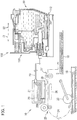
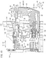
- Fig. 1 illustrates a state in which the ink cartridge 30 has been attached to the cartridge attaching unit 110, that is, Fig. 1 illustrates a state in which the ink cartridge 30 is in the attachment posture (first posture).
- the cartridge attaching unit 110 includes a case 101, ink needles 102, sensors 103, electrical contacts 106, locking portions 145, and a cover 108.
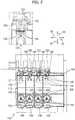
- the cartridge attaching unit 110 is adapted to accommodate four ink cartridges 30, which correspond to cyan, magenta, yellow, and black.
- the four ink cartridges 30 are arrayed in a direction perpendicular to the insertion direction 51 in a state where the four ink cartridges 30 are accommodated in the cartridge attaching unit 110.
- One ink needle 102, one sensor 103, and four electrical contacts 106 are provided corresponding to each of the four ink cartridges 30.
- the case 101 which constitutes a wall of the cartridge attaching unit 110, has a box-like shape that has a top surface that defines a top part of an internal space of the case 101, a bottom surface that defines a bottom part of the internal space, an end surface connecting the top part and the bottom part together, and the opening 112.
- the opening 112 is positioned to confront the end surface in the insertion direction 51 and removal direction 52, and the opening 112 can be exposed to a user interface surface of the printer 10.
- the interface surface is the surface which the user confronts when using the printer 10.
- the ink cartridge 30 is inserted into and removed from the case 101 through the opening 112.
- Guide grooves 109 are formed at the top surface and bottom surface.
- the ink cartridge 30 can be inserted in the insertion direction 51 and removal direction 52 in Fig. 10 by guiding the upper edge and lower edge of the ink cartridge 30 along the guide grooves 109.
- Three plates 104 are provided in the case 101 for partitioning the internal space into four spaces each elongated vertically. One ink cartridge 30 is accommodated in each of these spaces partitioned by the plates 104.
- the ink needle 102 (an example of a liquid supply tube) is provided at a lower portion of the end surface of the case 101.
- the ink needle 102 is tubular in shape and made from resin.
- the ink needle 102 is disposed at a position corresponding to an ink supply portion 34 (an example of a liquid supply portion) of the ink cartridge 30 in the state of attachment of the ink cartridge 30 to the cartridge attaching unit 110.
- the ink needle 102 protrudes from the end surface of the case 101 in the removal direction 52.
- the cylindrical guide 105 is provided around the ink needle 102.
- the guide 105 protrudes from the end surface of the case 101 in the removal direction 52.
- the protrusion end of the guide 105 is open.
- the ink needle 102 is disposed at the center of the guide 105. In other words, the ink needle 102 is disposed concentrically with the guide 105.
- the guide 105 is shaped so as to conform with the shape of the ink supply portion 34 of the ink cartridge 30 so that the ink supply portion 34 can be advanced into the guide 105.
- the ink supply portion 34 of the ink cartridge 30 enters the guide 105 (see Fig. 12 ).
- the ink needle 102 is inserted into an ink supply opening 71 ( Fig. 6 ) formed in the ink supply portion 34.
- a valve body 77 ( Fig. 6 ) in the ink supply portion 34 is moved.
- the ink needle 102 and ink supply portion 34 are connected with each other.
- ink retained in a retaining chamber 36 ( Fig. 6 ) formed in the ink cartridge 30 flows into the ink tube 20 connected to the ink needle 102 through an internal space of a cylindrical wall 73 formed in the ink supply portion 34 and the internal space of the ink needle 102.
- the end face of the ink needle 102 can be flat or pointed.
- the locking portion 145 extends in the leftward direction 56 and the rightward direction 55 of the case 101 in the vicinity of the top surface of the case 101 and in the vicinity of the opening 112.
- the locking portion 145 is a rod-like member extending in the leftward direction 56 and the rightward direction 55.
- the locking portion 145 is, for example, a metal cylinder. Both ends of the locking portion 145 in the leftward direction 56 and the rightward direction 55 are secured to walls that define both ends of the case 101 in the leftward direction 56 and the rightward direction 55. Therefore, the locking portion 145 is immovable relative to the case 101. For example, the locking portion 145 is not pivotally movable relative to the case 101.
- the locking portion 145 extends in the leftward direction 56 and the rightward direction 55 across the four spaces in which four ink cartridges 30 can be accommodated. In each space in which the ink cartridge 30 is accommodated, a space is present around the locking portion 145. Therefore, the locking portion 145 is accessible to the ink cartridge 30 in the upward direction 54 or removal direction 52.
- the locking portion 145 is adapted to hold the ink cartridge 30 attached to the cartridge attaching unit 110 at the attached position.
- the ink cartridge 30 is brought into engagement with the locking portion 145 by inserting the ink cartridge 30 into the cartridge attaching unit 110 and pivotally moving the ink cartridge 30 to the attachment posture.
- the locking portion 145 is adapted to hold the ink cartridge 30 in the cartridge attaching unit 110 against urging force of a coil spring 78 of the ink cartridge 30 in the removal direction 52.
- each electrical contact 106 is provided in correspondence to four electrodes 65 (see Fig. 3 ) of the ink cartridge 30, which will be described later.
- Each electrical contact 106 is formed of an electrically conductive and resilient member such that the electrical contact 106 is deformable in the upward direction 54.
- Four sets of four electrical contacts 106 are provided in correspondence to four ink cartridges 30 that can be accommodated in the case 101. Incidentally, there is no limitation on the number of electrical contacts 106 and the number of electrodes 65, and any number of electrical contacts 106 and any number of electrodes 65 can be used.
- Each electrical contact 106 is electrically connected to an arithmetic unit through an electric circuit.
- the arithmetic unit includes, for example, a central processing unit (CPU), a read-only memory (ROM), and a random-access memory (RAM).
- the arithmetic unit may be configured as a control unit for the printer 10.
- a voltage Vc is applied to the electrode 65, the electrode 65 is grounded, or electric power is supplied to the electrode 65.
- IC integrated circuit
- a rod 125 is provided on the end surface of the case 101 and at a position above the ink needle 102.
- the rod 125 protrudes from the end surface of the case 101 in the removal direction 52.
- the rod 125 has a semi-circular shaped or an inverted U shaped cross-section orthogonal to the removal direction 52.
- a rib protrudes upwardly from the topmost position of the rod 125 and extends in the removal direction 52.
- the rod 125 is inserted into a recess 96 formed below an IC board 64 in the ink cartridge 30 in a state where the ink cartridge 30 is attached to the cartridge attaching unit 110, that is, in a state where the ink cartridge 30 is positioned at the attached position.
- the sensor 103 is provided on the top surface of the case 101.
- the sensor 103 has a light emitting portion and a light receiving portion.
- the light emitting portion is disposed rightward of the light receiving portion in the rightward direction 55 or leftward thereof in the leftward direction 56 with a space therebetween.
- a detection portion 62 provided in the ink cartridge 30 is located between the light emitting portion and the light receiving portion.
- the light emitting portion and the light receiving portion are disposed opposite to each other so as to interpose the detection portion 62 therebetween in a state where the attachment of ink cartridge 30 to the cartridge attaching unit 110 is completed.
- the sensor 103 outputs a different detection signal depending on whether light emitted from the light emitting portion has been received by the light receiving portion. For example, when the light receiving portion cannot receive light emitted from the light emitting portion (that is, the light receiving intensity at the light receiving portion is lower than a predetermined intensity), the sensor 103 outputs a low-level signal, the signal level of which is lower than a threshold level. On the other hand, when the light receiving portion receives light emitted from the light emitting portion (that is, the light receiving intensity at the light receiving portion is not less than the predetermined intensity), the sensor 103 outputs a high-level signal, the signal level of which is not less than the threshold level.
- the cover 108 is provided so as to open and close an opening 22 formed in a wall of a casing 14 constituting an outer shape of the printer 10, the wall being in confrontation with a user when using the printer 10.
- the case 101 is positioned in an internal space of the casing 14 such that the opening 112 is in conformance with the opening 22, that is, such that the opening 112 is disposed within the opening 22 when viewed in the forward direction 57.
- the ink cartridge 30 can be inserted into and detached from the case 101 through the openings 22 and 112.
- the cover 108 is pivotally movable about a pivot axis 115.
- the pivot axis 115 extends in parallel with a mounting surface on which the printer 10 is mounted, that is, the pivot axis 115 extends in a horizontal direction. In the present embodiment, the pivot axis 115 extends in the rightward direction 55 and the leftward direction 56.
- the cover 108 has an outer shape in conformance with a size of the opening 22. More specifically, the outer shape of the cover 108 is generally rectangular capable of covering the opening 22.
- the cover 108 has a closed posture closing the opening 22 of the casing 14. As illustrated in Fig. 8 , the ink cartridge 30 cannot be removed from and inserted into the cartridge attaching unit 110 when the cover 108 is at its closed posture.
- the cover 108 allows the opening 112 of the case 101 to be exposed to an outside when the cover 108 is at its open posture where the cover 108 opens the opening 22 of the casing 14.
- the ink cartridge 30 can be removed from and inserted into the cartridge attaching unit 110 when the cover 108 is at its open posture.
- the cover 108 has an outer surface 116 and an inner surface 117 (as an example of a second portion).
- the outer surface 116 forms a part of a rear wall of the casing 14 when the cover 108 is at its closed posture.
- the inner surface 117 is in confrontation with the case 101 when the cover 108 is at its closed posture.
- a locking pawl 118 protrudes from the inner surface 117.
- the locking pawl 118 is adapted to engage a locked portion 119 provided at the casing 14 and disposed at a position adjacent to an upper end of the opening 22 in order to maintain closed posture of the cover 108.
- the locked portion 119 is tapered toward its upper end, and is pin shaped.
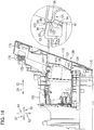
- the locked portion 119 is movable in the downward direction 53 and the upward direction 54 at a position adjacent to the upper end of the opening 22 of the casing 14, and is urged in the upward direction 54 by a coil spring 128 (see Fig. 14 ).
- Protrusions 121 protrude from the inner surface 117 at position closer to the pivot axis 115 than the locking pawl 118 to the pivot axis 115. Totally five protrusions 121 are arrayed and spaced away from each other in an extending direction of the pivot axis 115.
- each of the three intermediate protrusions 121 is positioned between the neighboring ink cartridges 30, and one protrusion 121 and remaining one protrusion 121 are positioned at rightmost end portion (i.e., rightward of the rightmost ink cartridge 30) and leftmost end portion (i.e., leftward of the leftmost ink cartridge 30) in the leftward direction 56 and the rightward direction 55, respectively.
- the intermediate three protrusions 121 have the structure identical to each other except for their positioning.
- the rightmost protrusion 121 and the leftmost protrusion 121 have the structure identical to the intermediate three protrusions 121 except that a dimension in the leftward direction 56 and the rightward direction 55 of the rightmost and leftmost protrusions is different from each other ( Fig. 9 ).
- One of the intermediate three protrusions 121 will be described.
- the protrusion 121 protrudes from the inner surface 117 of the cover 108, and is plate shaped elongated in the extending direction of the pivot axis 115.
- a distance between the protrusion 121 and the pivot axis 115 is so determined that the protrusion 121 when the cover 108 is at its closed posture can be positioned in a recessed portion 95 ( Figs. 3A and 4A ) positioned between a manipulation portion 90 and a sub-upper surface 91 of the ink cartridge 30 attached to the cartridge attaching unit 110.
- the recessed portion 95 is an example of a recess.
- the protrusion 121 has a tip end surface 122 and an engagement portion 123.
- the engagement portion 123 is adapted to engage a manipulation surface 92 of the manipulation portion 90 when the tip end surface 122 of the protrusion 121 is in abutment with the manipulation portion 90 of the ink cartridge 30.
- the engagement portion 123 is positioned at one end of the tip end surface 122, the one end being positioned farther from the pivot axis 115 than another end of the tip end surface 122 from the pivot axis 115.
- the engagement portion 123 protrudes further in a direction away from the inner surface 117 relative to the tip end surface 122. Further, the engagement portion 123 is provided over a length of the tip end surface 122 in the leftward direction 56 and the rightward direction 55.
- the engagement portion 123 is tapered toward its tip as viewed in the leftward direction 56 or the rightward direction 55.
- the engagement portion 123 includes a distal end face 120 and a guide surface 124.
- the distal end face 120 is positioned farther from the pivot axis 115 than the guide surface 124 to the pivot axis 115, that is, the distal end face 120 is positioned above the guide surface 124 at the closed posture of the cover 108.
- the distal end face 120 expands in the downward direction 53 and the upward direction 54 when the cover 108 is at its closed posture. In the other words, the distal end face 120 has a dimension in the downward direction 53 and the upward direction 54 when the cover 108 is at its closed posture.
- the guide surface 124 is positioned closer to the pivot axis 115 than the distal end face 120 to the pivot axis 115, that is, the guide surface 124 is positioned below the distal end face 120 when the cover 108 is at its closed position.
- the guide surface 124 and the tip end surface 122 define an obtuse angle therebetween.
- the tip end surface 122 expands in the downward direction 53 and the upward direction 54 when the cover 108 is at its closed posture.
- the tip end surface 122 has a dimension in the downward direction 53 and the upward direction 54 when the cover 108 is at its closed posture. Accordingly, when the cover 108 is at its closed posture, the guide surface 124 faces in the insertion direction 51 and the downward direction 53 ( Fig. 16 ).
- the guide surface 124 guides the manipulation portion 90 in order for the ink cartridge 30 to change its posture toward a second posture.
- Each of the three intermediate protrusions 121 is accommodated between neighboring ribs 94 provided at the neighboring recessed portions 95 of the neighboring ink cartridges 30 when the ink cartridges 30 are locked to the cartridge attaching unit 110.
- the rightmost protrusion 121 is positioned rightward of the rib 94 in the recessed portion 95 of the rightmost ink cartridge 30 in the rightward direction 55
- the leftmost protrusion 121 is positioned leftward of the rib 94 in the recessed portion 95 of the leftmost ink cartridge 30 in the leftward direction 56.
- the neighboring protrusions 121 define a gap length therebetween in the rightward direction 55 and the leftward direction 56 slightly greater than a dimension (thickness) of the rib 94 of the ink cartridge 30 in the rightward direction 55 and the leftward direction 56.
- An abutment portion 126 is provided at the inner surface 117 of the cover 108 at a position closer to the pivot axis 115 than the protrusions 121 to the pivot axis 115.
- the abutment portion 126 bulges in a direction away from the inner surface 117.
- the abutment portion 126 has a width in the rightward direction 55 and the leftward direction 56 approximately equal to a width of a combined five protrusions 121 in the rightward direction 55 and the leftward direction 56, that is, a distance from a right end of the rightmost protrusion 121 to a left end of the leftmost protrusion 121 in the rightward direction 55 and the leftward direction 56.
- the abutment portion 126 has a right end substantially in coincidence with the right end of the rightmost protrusion 121 and has a left end substantially in coincidence with the left end of the leftmost protrusion 121 in the rightward direction 55 and the leftward direction 56.
- the abutment portion 126 is in confrontation with a lower portion 41L of a rear surface 41 of the ink cartridge 30 that is in locked state, when the cover 108 is at its closed posture.
- the protruding length of the abutment portion 126 from the inner surface 117 is smaller than the protruding length of the protrusions 121 from the inner surface 117.
- the abutment portion 126 has a tip end surface 127 extending in parallel to the inner surface 117. Further, the tip end surface 127 is approximately parallel to the lower portion 41L of the rear surface 41 of the ink cartridge 30 that is in the locked state when the cover 108 is at its closed posture.
- the protrusions 121 accommodated in the recessed portions 95 of the ink cartridges 30 prevents the ink cartridges 30 from pivotally moving from the first posture (locked state) to the second posture (unlocked state) in the cartridge attaching unit 110 when the cover 108 is at the closed posture.
- the abutment portion 126 is brought into abutment with the lower portion 41L of the rear surface 41 of the ink cartridge 30 that is in the unlocked state, to thus move the ink cartridge 30 that is at the second posture in the insertion direction 51 to a position where the manipulation portion 90 and the protrusions 121 can abut against each other.
- the protrusions 121 are brought into engagement with the manipulation portion 90 of the ink cartridge 30 that is at the second posture.
- the protrusions 121 move the ink cartridge 30 in the insertion direction 51 while the protrusions 121 are in engagement with the manipulation portion 90 and holds the ink cartridge 30 so as to prevent the ink cartridge 30 from pivotally moving to the first posture.
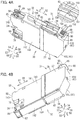
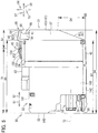
- the ink cartridge 30 illustrated in Figs. 3 through 6 is a vessel in which ink is retained.
- a space formed in the ink cartridge 30 is the retaining chamber 36 (an example of a liquid retaining chamber).
- the retaining chamber 36 is defined by an internal frame 35 accommodated in a rear cover 31 and a front cover 32, those forming an outer shape of the ink cartridge 30.
- the retaining chamber 36 can be defined by the rear cover 31 and the front cover 32.
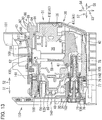
- the locked state (first posture) of the ink cartridge 30 is illustrated in Figs. 3 through 6 and 13 .
- the ink cartridge 30 has a front surface 140, the rear surface 41, upper surfaces 39 and 141 (as an example of a side surface), and lower surfaces 42 and 142, as described later in detail. In the orientation of the ink cartridge 30 illustrated in Figs.
- a direction extending from the rear surface 41 toward the front surface 140 is coincident with the insertion direction 51 and the forward direction 57
- a direction extending from the front surface 140 toward the rear surface 41 is coincident with the removal direction 52
- a direction extending from the upper surfaces 39 and 141 toward the lower surfaces 42 and 142 is coincident with the downward direction 53
- a direction extending from the lower surfaces 42 and 142 toward the upper surfaces 39 and 141 is coincident with the upward direction 54.
- the front surface 140 faces in the insertion direction 51 and in the forward direction 57
- the rear surface 41 faces in the removal direction 52
- the lower surfaces 42 and 142 face in the downward direction 53
- the upper surfaces 39 and 141 face in the upward direction 54
- the ink supply portion 34 faces in a direction crossing the direction of force of gravity.
- the ink cartridge 30 includes the rear cover 31 having a substantially rectangular parallelepiped shape, the front cover 32 forming the front surface 140, and the internal frame 35 defining the retaining chamber 36.
- the rear cover 31 and front cover 32 are assembled together to form the outside shape of the ink cartridge 30.
- the internal frame 35 is placed inside the combined rear cover 31 and front cover 32.
- the ink cartridge 30 is flat as a whole; the dimension in the rightward direction 55 and the leftward direction 56 is small, and the dimension in the downward direction 53 and the upward direction 54 and the dimension in the forward direction 57 and the backward direction 58 are larger than the dimension in the rightward direction 55 and the leftward direction 56.
- the front surface 140 of the front cover 32 faces in the insertion direction 51 (the forward direction 57) and the rear surface 41 of the rear cover 31 faces in the removal direction 52 (the backward direction 58). That is, the rear surface 41 is disposed opposite to the front surface 140 of the front cover 32 so as to interpose the retaining chamber 36 between the rear surface 41 and the front surface 140. Note that, in the state of the insertion, the ink supply portion 34 of the ink cartridge 30 faces in a direction crossing the direction of force of gravity.
- the rear cover 31 is formed like a box shape with side surfaces 37 and 38 which are spaced apart from each other in the rightward direction 55 and the leftward direction 56, the upper surface 39 facing in the upward direction 54, and the lower surface 42 facing in the downward direction 53.
- the upper surface 39 and the lower surface 42 extend from the rear surface 41 in the insertion direction 51.
- the rear cover 31 has an open end opening forward in the forward direction 57.
- the internal frame 35 is inserted into an interior of the rear cover 31 through the open end. That is, the rear cover 31 covers the rear portion of the internal frame 35.
- the lower surface 42 is disposed opposite to the upper surface 39 so as to interpose the retaining chamber 36 between the lower surface 42 and the upper surface 39.
- the rear surface 41 has an upper portion 41U and the lower portion 41L.
- the upper portion 41U is positioned above the lower portion 41L in the upward direction 54.
- the lower portion 41L is positioned below the upper portion 41U in the downward direction 53.
- the lower portion 41L is positioned forward of the upper portion 41U in the forward direction 57.
- Both the upper portion 41U and the lower portion 41L are flat surfaces, and crossing each other but not orthogonal to each other.
- the lower portion 41L is inclined with respect to the downward direction 53 and the upward direction 54 such that the lower portion 41L approaches the front surface 140 as the lower portion 41L approaches the lower surface 42.
- a sheet indicating characters such as "PUSH”, a symbol such as an arrow, or a figure indicating a push with a finger, or the like is pasted to the upper portion 41U as illustrated in Fig. 7B .
- a protrusion 43 is formed on the upper surface 39 of the rear cover 31.
- the protrusion 43 extends in the forward direction 57 and the backward direction 58 at a center of the upper surface 39 in the rightward direction 55 and the leftward direction 56.
- the protrusion 43 has a locking surface 151 facing in the backward direction 58.
- the locking surface 151 extends in the downward direction 53 and the upward direction 54. In other words, the locking surface 151 has a dimension in the downward direction 53 and the upward direction 54.
- the locking surface 151 has a rightmost edge in the rightward direction 55 and a leftmost edge in the leftward direction 56.
- a reinforcing surface 152 extends from the rightmost edge of the locking surface 151, and intersects with the locking surface 151.
- a reinforcing surface 153 extends from the leftmost edge of the locking surface 151, and intersects with the locking surface 151.
- the reinforcing surfaces 152 and 153 extend diagonally forward in the forward direction 57 from the locking surface 151 so as to form an acute angle with respect to an imaginary flat surface containing the locking surface 151 and extending in the downward direction 53, the upward direction 54, the rightward direction 55, and the leftward direction 56.
- the strength of the protrusion 43 is increased, reducing the risk of damage or breakage to the locking surface 151. Since the reinforcing surfaces 152 and 153 do not extend beyond the locking surface 151 in the backward direction 58, the reinforcing surfaces 152 and 153 do not come into contact with the locking portion 145. Therefore, even if the locking surface 151 is slidingly moved with respect to the locking portion 145, sliding resistance is not increased. In other words, even if the locking surface 151 is slidingly moved with respect to the locking portion 145, the presence of the reinforcing surfaces 152 and 153 do not increase sliding resistance.
- a horizontal surface 154 extends from the locking surface 151 in the forward direction 57.
- the horizontal surface 154 expands in the rightward direction 55, the leftward direction 56, the forward direction 57, and the backward direction 58.
- an inclined surface 155 extends from the horizontal surface 154 in the forward direction 57.
- the inclined surface 155 faces in the upward direction 54 and the forward direction 57. Therefore, the inclined surface 155 is visible when the ink cartridge 30 is viewed in the downward direction 53, and also visible when the ink cartridge 30 is viewed in the backward direction 58.
- the locking portion 145 is smoothly guided by the inclined surface 155 and horizontal surface 154 beyond the locking surface 151 in the backward direction 58 while maintaining a contact of the locking portion 145 with the inclined surface 155 and horizontal surface 154.
- the inclined surface 155 has a rightmost edge in the rightward direction 55 and a leftmost edge in the leftward direction 56.
- a reinforcing surface 156 extends from the rightmost edge of the inclined surface 155, and intersects with the inclined surface 155.
- a reinforcing surface 157 extends from the leftmost edge of the inclined surface 155, and intersects with the inclined surface 155.
- the reinforcing surfaces 156 and 157 extend diagonally downward in the downward direction 53 from the inclined surface 155 so as to form an acute angle with respect to an imaginary flat surface containing the inclined surface 155 and extending in the rightward direction 55 and the leftward direction 56.
- the strength of the protrusion 43 is increased, reducing the risk of damage or breakage to the inclined surface 155. Since the reinforcing surfaces 156 and 157 do not extend beyond the inclined surface 155 in the upward direction 54, the reinforcing surfaces 156 and 157 do not come into contact with the locking portion 145. Therefore, even if the inclined surface 155 is slidingly moved with respect to the locking portion 145, sliding resistance is not increased. In other words, even if the inclined surface 155 is slidingly moved with respect to the locking portion 145, the presence of the reinforcing surfaces 156 and 157 do not increase sliding resistance.
- the manipulation portion 90 is provided on the upper surface 39 of the rear cover 31 and at a position backward of the locking surface 151 in the backward direction 58.
- the sub-upper surface 91 (as an example of a sub-side surface) is provided below the remaining upper surface 39 in the downward direction 53.
- the manipulation portion 90 (as an example of a first portion) is disposed above and spaced away from the sub-upper surface 91 through the recessed portion 95.
- the recessed portion95 is open in the removal direction 52, i.e., in the backward direction 58.
- the manipulation portion 90 is shaped like a flat plate such that the manipulation portion 90 protrudes beyond the protrusion 43 in the upward direction 54 from the vicinity of a boundary between the sub-upper surface 91 and the remaining upper surface 39 and is then bent diagonally in the backward direction 58 and in the downward direction 53.
- the rib 94 is provided between the manipulation portion 90 and the sub-upper surface 91. More specifically, the rib 94 extends from the sub-upper surface 91 to a back surface 99 ( Fig. 5 ) of the manipulation portion 90 and protrudes in the backward direction 58. As illustrated in Fig.
- the dimension of the rib 94 in the rightward direction 55 and the leftward direction 56 is smaller than the dimensions of the manipulation portion 90 in the rightward direction 55 and the leftward direction 56 and is also smaller than the sub-upper surface 91 in the rightward direction 55 and the leftward direction 56.
- the manipulation portion 90 has the manipulation surface 92 facing in the upward direction 54 and in the backward direction 58.
- the manipulation surface 92 is opposite to the back surface 99 in the upward direction 54 and the downward direction 53.
- the manipulation surface 92 and sub-upper surface 91 are overlapped with each other in the forward direction 57 and the backward direction 58.
- the manipulation surface 92 has a plurality of rib-like protrusions 93 extending in the rightward direction 55 and the leftward direction 56, and spaced apart from each other in the forward direction 57 and the backward direction 58. The user can easily recognize the manipulation surface 92 because of the rib-like protrusions 93.
- finger slippage on the manipulation surface 92 can be restrained.
- the manipulation surface 92 is visible when the ink cartridge 30 is viewed in the downward direction 53, and also visible when the ink cartridge 30 is viewed in the forward direction 57.
- the manipulation surface 92 is visible when the ink cartridge 30 is viewed in a direction from the upper surface 39 to the lower surface 42, and also visible when the ink cartridge 30 is viewed in a direction from the rear surface 41 to the front surface 140.
- the manipulation surface 92 is adapted for user's manipulation to take out the ink cartridge 30 attached to the cartridge attaching unit 110.
- the manipulation portion 90 is rigidly secured to the rear cover 31 by being integrally molded with the rear cover 31, such that relative movement between the manipulation portion 90 and the rear cover 31 does not occur, for example, pivotal movement of the manipulation portion 90 relative to the rear cover 31 does not occur. Therefore, a force given by the user to the manipulation surface 92 can be directly transmitted to the rear cover 31 without changing the direction.
- the manipulation portion 90 is configured to also avoid relative movement, such as pivotal movement, with respect to the internal frame 35 and retaining chamber 36.
- a guide surface 89 extends from the manipulation surface 92 and is positioned backward of the manipulation surface 92 in the backward direction 58.
- the guide surface 89 faces in the backward direction 58 and the upward direction 54.
- the guide surface 89 is a surface accessible to the engagement portion 123 of the protrusion 121 of the cover 108 in the insertion direction 51.
- the front cover 32 is box shaped having side surfaces 143 and 144, the upper surface 141, and the lower surface 142.
- the side surfaces 143 and 144 are spaced away from each other in the rightward direction 55 and the leftward direction 56 and extend from the front surface 140 in the backward direction 58.
- the upper surface 141 and lower surface 142 are spaced away from each other in the downward direction 53 and the upward direction 54 and extend from the front surface 140 in the backward direction 58.
- the front cover 32 has an open end opening backward in the backward direction 58.
- the internal frame 35 is inserted into the front cover 32 through the open end. That is, the front cover 32 covers a front portion of the internal frame 35 which is not covered by the rear cover 31.
- the upper surface 141 of the front cover 32 forms the upper surface of the ink cartridge 30 together with the upper surface 39 of the rear cover 31, and the lower surface 142 of the front cover 32 forms the lower surface of the ink cartridge 30 together with the lower surface 42 of the rear cover 31.
- the lower surface 142 of the front cover 32 extends in the forward direction 57 and the backward direction 58, and the lower surface 42 of the rear cover 31 is inclined so as to face in the downward direction 53 and in the backward direction 58.
- the side surfaces 143 and 144 of the front cover 32 form the side surfaces of the ink cartridge 30 together with the side surfaces 37 and 38 of the rear cover 31.
- the front surface 140 of the front cover 32, the front surface 140 forming the front surface of the ink cartridge 30, and the rear surface 41 of the rear cover 31, the rear surface 41 forming the rear surface of the ink cartridge 30, are spaced apart from each other in the forward direction 57 and the backward direction 58.
- each of the front surface, rear surface, upper surface, lower surface, and side surfaces of the ink cartridge 30 is not limited to a single flat plane. That is, the front surface is a surface that is visible when the ink cartridge 30 placed in the first posture is viewed in the backward direction 58, and the front surface is positioned frontward of a center of the ink cartridge 30 in the forward direction 57 and the backward direction 58.
- the rear surface is a surface that is visible when the ink cartridge 30 placed in the first posture is viewed in the forward direction 57, and the rear surface is positioned rearward of the center of the ink cartridge 30 in the forward direction 57 and the backward direction 58.
- the upper surface is a surface that is visible when the ink cartridge 30 placed in the first posture is viewed in the downward direction 53, and the upper surface is positioned upward of a center of the ink cartridge 30 in the downward direction 53 and the upward direction 54.
- the lower surface is a surface that is visible when the ink cartridge 30 placed in the first posture is viewed in the upward direction 54, and the lower surface is positioned downward of the center of the ink cartridge 30 in the downward direction 53 and the upward direction 54. The same is true with respect to the side surfaces.
- the recess 96 recessed in the backward direction 58 is formed at an upper portion of the front surface 140 of the front cover 32.
- the recess 96 is adapted to allow the rod 125 to be inserted thereinto in the state where the ink cartridge 30 is attached to the cartridge attaching unit 110. Therefore, a cross-sectional shape of the recess 96 taken along a plane perpendicular to the forward direction 57 and the backward direction 58 corresponds to a cross-sectional shape of the rod 125.
- a hole 97 passing through the front cover 32 in the backward direction 58 is formed at a lower portion of the front surface 140 of the front cover 32.
- the hole 97 allows the ink supply portion 34 of the internal frame 35 to be exposed to an outside. Therefore, the position, dimensions, and shape of the hole 97 correspond to those of the ink supply portion 34 of the internal frame 35.
- a first protruding portion 85 and a second protruding portion 86 are provided on the front surface 140 of the front cover 32.
- the first protruding portion 85 protrudes from the upper portion of the front cover 32 in the forward direction 57.
- the recess 96 is formed at a tip end portion of the first protruding portion 85.
- a tip end of the first protruding portion 85 forms a part of the front surface 140.
- the second protruding portion 86 protrudes from the lower portion of the front surface 140 in the forward direction 57 and is positioned at a position below the ink supply portion 34.
- a hole 98 passing through the front cover 32 in the downward direction 53 is formed at the upper surface 141 of the front cover 32.
- the hole 98 allows the detection portion 62 of the internal frame 35 to be exposed to the outside. Therefore, the position, dimension, and shape of the hole 98 correspond to those of the detection portion 62 of the internal frame 35.
- the IC board 64 is disposed on the upper surface 141 of the front cover 32 and above the first protruding portion 85, that is, the IC board 64 is positioned above the ink supply portion 34.
- the IC board 64 is electrically connected to the four electrical contacts 106 (see Fig. 2 ) arrayed in the rightward direction 55 and the leftward direction 56 not only in a state where the ink cartridge 30 has been attached to the cartridge attaching unit 110 but also in a state where the ink cartridge 30 is on its way to the cartridge attaching unit 110 (during attachment of the ink cartridge 30 to the cartridge attaching unit 110).
- the IC is a semiconductor integrated circuit storing information about the ink cartridge 30 such as a lot number, and a date and time of manufacturing, and data indicative of ink colors in such a way that the data can be read.
- Each of the electrodes 65 is electrically connected to the IC.
- Each electrode 65 extends in the forward direction 57 and the backward direction 58.
- the four electrodes 65 are spaced apart from each other in the rightward direction 55 and the leftward direction 56.
- Each electrode 65 is exposed to an upper surface of the IC board 64 so as to be electrically accessible.
- the internal frame 35 is tubular shape having a pair of end surfaces being open in the rightward direction 55 and the leftward direction 56.
- the pair of open end surfaces of the internal frame 35 are sealed with films (not illustrated), forming the retaining chamber 36 in which ink is retainable.
- a front surface 40 defining the retaining chamber 36 faces a back surface of the front surface 140 of the front cover 32 when the internal frame 35 is inserted into the front cover 32.
- the ink supply portion 34 is disposed at the front surface 40.
- the ink supply portion 34 protrudes from the front surface 40 of the internal frame 35 in the forward direction 57.
- the ink supply portion 34 has a cylindrical outside shape and protrudes toward the outside through the hole 97 formed in the front surface 140 of the front cover 32.
- the ink supply portion 34 has the hollow cylindrical wall 73 and a sealing member 76 and a cap 79 those being attached to the cylindrical wall 73.
- the ink supply portion 34 faces in a direction crossing the direction of force of gravity.
- the ink supply portion 34 faces in a direction crossing the direction of force of gravity.
- the cylindrical wall 73 extends from the interior of the retaining chamber 36 to the outside.
- the leading end of the cylindrical wall 73 in the removal direction 52 is open to the retaining chamber 36.
- the leading end of the cylindrical wall 73 in the insertion direction 51 is open to the outside of the ink cartridge 30.
- the cylindrical wall 73 allows the retaining chamber 36 to communicate with the outside of the ink cartridge 30 through the hollow space. That is, the ink supply portion 34 is adapted to supply ink retained in the retaining chamber 36 to the outside of the ink cartridge 30 through the hollow space of the cylindrical wall 73.
- the sealing member 76 and cap 79 are attached to the leading end of the cylindrical wall 73 in the insertion direction 51.
- the valve body 77 and the coil spring 78 are accommodated in the hollow space of the cylindrical wall 73.
- the valve body 77 and coil spring 78 are adapted to selectively switch the state of the ink supply portion 34. More specifically, the valve body 77 and coil spring 78 are adapted to selectively switch from a first state to a second state and vice versa.
- the first state ink flow from the retaining chamber 36 to the outside of the ink cartridge 30 through the hollow space of the cylindrical wall 73 ( Fig. 13 ).
- the second state flowing of the ink from the hollow space of the cylindrical wall 73 to the outside of the ink cartridge 30 is prevented ( Fig. 6 ).
- the ink supply opening 71 is closed and opened by the valve body 77.
- the coil spring 78 is adapted to bias the valve body 77 in the forward direction 57. Therefore, the valve body 77 closes the ink supply opening 71 of the sealing member 76 in a state where no external force is applied.
- the sealing member 76 is disposed at the tip end portion of the cylindrical wall 73.
- the sealing member 76 has a radially center portion at which a through-hole is formed.
- the sealing member 76 is a discoid member formed with the through-hole.
- the sealing member 76 is made from an elastic material such as a rubber material or an elastomer.
- the through-hole extends in the forward direction 57 and the backward direction 58 at the radial center portion of the sealing member 76 to form a cylindrical inner surface, and the ink supply opening 71 is defined by the cylindrical inner surface.
- the ink supply opening 71 has an inner diameter slightly smaller than an outer diameter of the ink needle 102.
- the cap 79 is fitted to an outer surface of the cylindrical wall 73, so that the sealing member 76 is in liquid-tight contact with a tip end of the cylindrical wall 73.
- the ink needle 102 enters the ink supply opening 71 by the insertion of the ink cartridge 30 into the cartridge attaching unit 110 in a state where the valve body 77 closes the ink supply opening 71.
- the outer peripheral surface of the ink needle 102 comes into contact with the cylindrical inner surface defining the ink supply opening 71 in a liquid-tight manner, while the ink needle 102 elastically deforms the sealing member 76.
- the end of the ink needle 102 is brought into abutment with the valve body 77, as a result of passing of the end of the ink needle 102 through the sealing member 76 and entering the hollow space of the cylindrical wall 73.
- the ink needle 102 By further insertion of the ink cartridge 30 into the cartridge attaching unit 110, the ink needle 102 causes the valve body 77 to move in the backward direction 58 against the biasing force of the coil spring 78. This enables ink retained in the retaining chamber 36 to flow to the tip end portion of the ink needle 102 through the hollow space of the cylindrical wall 73.
- the tip end portion of the ink needle 102 is formed with a through-hole.
- the ink flows from the hollow space of the cylindrical wall 73 to an internal space of the ink needle 102 through the through-hole. Accordingly, the ink retained in the retaining chamber 36 can flow to the outside through the hollow space of the cylindrical wall 73 and the ink needle 102.
- the valve body 77 which closes the ink supply opening 71 is not necessarily provided in the ink supply portion 34.
- the ink supply opening 71 can be closed by a film or the like.
- the ink needle 102 breaks the film, so that the tip end portion of the ink needle 102 enters the hollow space of the cylindrical wall 73 through the ink supply opening 71.
- the ink supply opening 71 may be normally closed by the elastic deformation of the sealing member 76. In the latter case, the ink supply opening 71 becomes open by the pressure from the ink needle 102, the pressure being generated upon insertion of the ink needle 102.
- the internal frame 35 is provided with the detection portion 62 protruding in the upward direction 54 from the upper surface thereof.
- the detection portion 62 is convex shaped whose internal space is in communication with the retaining chamber 36.
- the detection portion 62 has light transmissivity enabling light to pass in the rightward direction 55 and the leftward direction 56.
- the detection portion 62 is exposed to the outside through the hole 98 of the front cover 32.
- a detection member 59 is positioned in the retaining chamber 36 of the internal frame 35.
- the detection member 59 is supported by a pivot shaft 61 extending in the rightward direction 55 and the leftward direction 56 and is pivotally movable about the pivot shaft 61.
- the detection member 59 has a float 63 whose specific gravity is lower than that of the ink retained in the retaining chamber 36. Therefore, the float 63 generates buoyancy while the float 63 is in the ink in the retaining chamber 36.
- the detection member 59 is pivotally moved in the counterclockwise direction in Fig. 6 because of the buoyancy of the float 63.
- a portion of the detection member 59 is entered the interior of the detection portion 62, and is in contact with a wall defining a forward end of the detection portion 62 in the forward direction 57. Consequently, the pivot posture of the detection member 59 can be maintained.
- the detection member 59 shuts off the light emitted from the sensor 103, and performs other processing on the light, the light being configured to advance through the detection portion 62 in the rightward direction 55 or the leftward direction 56.
- the detection member 59 when the light emitted from the light emitting portion of the sensor 103 reaches one of the right surface and left surface of the detection portion 62, the detection member 59 reduces intensity of light passing through the remaining one of the right surface and left surface of the detection portion 62 and reaching the light receiving portion of the sensor 103 blow a predetermined intensity, for example, zero.
- the detection member 59 may completely shut off the light so as to completely prevent light from advancing in the rightward direction 55 or the leftward direction 56.
- the detection member 59 may partially absorb the light, or may change advancing direction of the light, or may cause total reflection of the light.
- the float 63 is lowered in accordance with the lowering of the liquid level. Accordingly, the detection member 59 is pivotally moved in the clockwise direction in Fig. 6 . By this pivotal movement in the clockwise direction, the portion of the detection member 59 having been entered into the interior of the detection portion 62 is moved to a position offsetting from a light path from the light emitting portion to the light receiving portion. Thus, intensity of light received at the light receiving portion of the sensor 103 is equal to or higher than the predetermined intensity.
- a distance D1 between the locking surface 151 and the front surface 140 is greater than a distance D2 between the locking surface 151 and the rear surface 41 (more specifically, the distance D2 between the locking surface 151 and the upper portion 41U of the rear surface 41).
- the distance D1 is smaller than a distance D3 between the manipulation surface 92 and the front surface 140 (more specifically, distance D3 between the manipulation surface 92 and the frontmost surface of the front surface 140).
- a distance D4 between a lower end of the upper portion 41U of the rear surface 41 and the lower surface 42 is greater than a distance D5 between a lower end of the lower portion 41L of the rear surface 41 and the lower surface 42 (in the depicted embodiment, the distance D5 is zero).
- a distance D6 between a frontmost edge of the upper portion 41U of the rear surface 41 and the front surface 140 is greater than a distance D7 between a frontmost edge of the lower portion 41L of the rear surface 41 and the front surface 140 (more specifically, the distance D7 between the frontmost edge of the lower portion 41L of the rear surface 41 and the frontmost surface of the front surface 140).
- the lower portion 41L of the rear surface 41 has a portion positioned between a central axis 72 of the ink supply opening 71 of the sealing member 76 and the lower surface 42 when viewed in the forward direction 57 or the backward direction 58.
- the central axis 72 passes through the center of the ink supply opening 71 and extends in a direction in which the ink supply opening 71 penetrates the sealing member 76.
- the valve body 77 closes the ink supply opening 71 of the sealing member 76. This blocks a flow of ink from the retaining chamber 36 to the outside of the ink cartridge 30. Further, as illustrated in Fig. 9 , for insertion of the ink cartridge 30 into the cartridge attaching unit 110, the cover 108 is opened by the user to be at its open posture.
- the ink cartridge 30 is inserted into the case 101 through the opening 112 of the cartridge attaching unit 110.
- the upper portion 41U of the rear surface 41 of the rear cover 31 is positioned rearward of the lower portion 41L in the removal direction 52. That is, the upper portion 41U is positioned closer to the user, than the lower portion 411 to the user.
- the user inserts the ink cartridge 30 into the cartridge attaching unit 110 in the insertion direction 51 while pressing the upper portion 41U.
- the user is prompted to push the upper portion 41U because the sheet pasted to the upper portion 41U indicates "PUSH" or another characters, a symbol such as an arrow, or a figure indicating a push with a finger, or the like, as described above.
- the second protruding portion 86 is disposed at the lower portion of the front cover 32.
- a rib part 87 protrudes from the lower surface 142 of the front cover 32 in the downward direction 53.
- the rib part 87 is brought into abutment with the upper surface of the lower guide groove 109.
- the front portion of the front cover 32 is lifted upward so that the lower surface 142 is inclined with respect to the insertion direction 51. That is, the rib part 87 of the front cover 32 and a rear portion of the lower surface 142 are in abutment with the upper surface of the lower guide groove 109.
- the cap 79 in the ink supply portion 34 starts to enter the cylindrical guide 105. Further, the recess 96 of the front cover 32 faces the rod 125, and the rod 125 starts to enter the recess 96.
- the cap 79 in the ink supply portion 34 is entered into the cylindrical guide 105, and the ink needle 102 is entered into the ink supply opening 71 to move the valve body 77 away from the sealing member 76 against the biasing force of the coil spring 78.
- the biasing force of the coil spring 78 is applied to the ink cartridge 30 in the removal direction 52.
- the rod 125 is entered into the recess 96 of the front cover 32 to support the front cover 32 from below.
- the IC board 64 reaches the lower side of the electrical contacts 106, so that each of the electrodes 65 is electrically connected to corresponding one of the electric contacts while the electrical contacts 106 are resiliently deformed upward. In this case, the IC board 64 is urged in the downward direction 53 because of the resilient deformation of the electrical contacts 106.
- the IC board 64 can be accurately positioned relative to the electrical contacts 106 because the rod 125 supports the front cover 32 from below. Incidentally, the rod 125 does not necessarily support the front cover 32 from below.
- the protrusion 43 of the rear cover 31 reaches the locking portion 145 and the inclined surface 155 slides on the locking portion 145.
- rotational moment is exerted on the ink cartridge 30 in the counterclockwise direction in Fig. 12 .
- the ink cartridge 30 is urged to be pivotally moved about the ink supply portion 34 in a clockwise direction in Fig. 12 against the rotational moment.
- the ink cartridge 30 is pivotally moved about a pivot axis, the pivot axis extending in the horizontal direction (in the present embodiment, the pivot axis extends in the rightward direction 55 and leftward direction 56) and passing through the center of the ink supply opening 71 of the sealing member 76 through which the ink needle 102 has been inserted. That is, the pivot axis about which the ink cartridge 30 is pivotally moved extends in a direction the same as the direction in which the pivot axis 115 of the cover 108 extends.
- the posture of the ink cartridge 30 illustrated in Fig. 12 is referred to as the "second posture (the unlocked state)."
- the "second posture” implies a posture of the entire ink cartridge 30.
- the locking surface 151 of the protrusion 43 is positioned below the locking portion 145 while the ink cartridge 30 is in the second posture.
- the above-described pivot center i.e., the pivot axis of the ink cartridge 30
- the above-described pivot center is overlapped with the IC board 64 in the insertion direction 51 while the ink cartridge 30 is in the second posture.
- the above-described pivot center is overlapped with the IC board 64 when viewed in the downward direction 53 or the upward direction 54. Therefore, the biasing force applied to the IC board 64 by the electrical contacts 106 does not produce rotational moment which pivotally moves the ink cartridge 30, or the biasing force produces extremely small rotational moment.
- the lower surface 42 of the rear cover 31 is in contact with or is positioned in the vicinity of the upper surface of the lower guide groove 109, while the ink cartridge 30 is in the second posture. Therefore, in the depicted embodiment, when the ink cartridge 30 is in the second posture, the lower surface 42 of the rear cover 31 is parallel to a horizontal plane. Further, the lower portion 41L of the rear surface 41 of the rear cover 31 is positioned further in the insertion direction 51 relative to the upper portion 41U while the ink cartridge 30 is in the second posture. In other words, the lower portion 41L is positioned frontward of the upper portion 41U in the forward direction 57 while the ink cartridge 30 is in the second posture.
- the ink cartridge 30 is pivotally moved about the pivot axis passing through the center of the ink supply opening 71 of the sealing member 76 through which the ink needle 102 has been inserted.
- the posture of the ink cartridge 30 illustrated in Fig. 13 is referred to as "the first posture (locked state)."
- the "first posture” implies a posture of the entire ink cartridge 30.
- the ink cartridge 30 is capable of changing its posture from the second posture to the first posture about the ink supply portion 34.
- the ink cartridge 30 is pivotally movable from the second posture to the first posture about the ink supply portion 34.
- the locking surface 151 faces the locking portion 145 in the removal direction 52 while the ink cartridge 30 is in the first posture.
- the rear cover 31 is brought into abutment with the locking portion 145 to generate an impact.
- the user recognizes completion of pressing the ink cartridge 30 in the insertion direction 51.
- the ink cartridge 30 moves in the removal direction 52 because of the biasing force of the coil spring 78 as soon as the user stops pressing the ink cartridge 30 in the insertion direction 51.
- the locking surface 151 facing the locking portion 145 in the removal direction 52 is brought into abutment with the locking portion 145 as a result of slight movement of the ink cartridge 30 in the removal direction 52. Consequently, the first posture of the ink cartridge 30 can be maintained, restricting movement of the ink cartridge 30 in the removal direction 52. That is, the ink cartridge 30 is subjected to positioning within the cartridge attaching unit 110, and the ink cartridge 30 is at the locked state where attachment to the cartridge attaching unit 110 is completed. Note that, in the locked state, the ink supply portion 34 faces in a direction crossing the direction of force of gravity.
- the user pivotally moves the cover 108 from its open posture illustrated in Fig. 14 to the closed posture illustrated in Fig. 15 , after the ink cartridge 30 is subjected to positioning in the cartridge attaching unit 110 and is in the locked state.
- the locking pawl 118 is engaged with the locked portion 119 when the cover 108 is at its closed posture.
- closed posture of the cover 108 can be maintained.
- each of the intermediate three protrusions 121 among the totally five protrusions 121 of the cover 108 is accommodated between ribs 94 in the recessed portions 95 defined by the neighboring ink cartridges 30 that are in the locked state.
- the rightmost protrusion 121 is positioned rightward of the rib 94 at the recessed portion 95 of the rightmost ink cartridge 30, and the leftmost protrusion 121 is positioned leftward of the rib 94 at the recessed portion 95 of the leftmost ink cartridge 30.
- each upper surface of each protrusion 121 accommodated in each recessed portion 95 is in contact with or is positioned adjacent to the back surface 99 of the manipulation portion 90.
- Such positional relationship between each protrusion 121 and each back surface 99 prevents each ink cartridge 30 from pivotally moving from the first posture to the second posture.
- the protrusion 121 is positioned adjacent to the back surface 99, i.e., in case where a gap is provided between the protrusion 121 and the back surface 99 at the closed posture of the cover 108, immediately after the ink cartridge 30 starts pivotal movement from the first posture to the second posture, the protrusion 121 is brought into abutment with the back surface 99 to prevent the ink cartridge 30 from moving from the first posture to the second posture.
- the locking surface 151 is positioned below the locking portion 145 in the downward direction 53, and the manipulation portion 90 is positioned above the recessed portion 95.
- the pivot axis 115 of the cover 108 extends in horizontal direction, and is positioned below the protrusions 121 when the cover 108 is at the closed posture.
- the abutment portion 126 is brought into abutment with the lower portion 41L of the rear surface 41 of the ink cartridge 30 that is in the unlocked state by the pivotal movement of the cover 108 from its open posture toward its closed posture.
- the ink cartridge 30 is pushed in the insertion direction 51 by the abutment portion 126 as illustrated in Fig. 16 , so that the unlocked ink cartridge 30 is moved in the insertion direction 51 to a position where the manipulation portions 90 can abut on the protrusions 121.
- the protrusions 121 are engaged with the manipulation portion 90 of the unlocked ink cartridge 30.
- the guide surface 124 of the protrusion 121 is brought into abutment with the guide surface 89 of the manipulation portion 90, and a force containing a component in the insertion direction 51 is imparted on the guide surfaces 124 and 89, so that the unlocked ink cartridge 30 is further urged such that the manipulation portion 90 is moved in the downward direction 53. That is, the unlocked ink cartridge 30 is moved in a direction away from the locked state.
- the engagement portion 123 of the protrusion 121 is engaged with the manipulation portion 90, or the tip end surface 122 of the protrusion 121 is in abutment with the manipulation portion 90, so that the ink cartridge 30 is further moved in the insertion direction 51 in accordance with pivotal movement of the cover 108 while the ink cartridge 30 is held so as not to pivotally move toward the first posture.
- Fig 17 illustrates a first length (distance) L1 and a second length (distance) L2.
- the first and second lengths L1, L2 are measured when the locking surface 151 is positioned at a stroke end position in the insertion direction 51 as a result of movement of the locking surface 151 past the locking portion 145 in the insertion direction 51 while the protrusion 121 is in abutment with the manipulation portion 90.
- the first length L1 is measured in the insertion direction 51 from a rear end of the manipulation portion 90 to the inner surface 117 of the cover 108. More specifically, in the present embodiment, the first length L1 is measured from the rear end of the manipulation portion 90 to a boundary between the inner surface 117 and the protrusion 121.
- the second length (distance) L2 is measured in the insertion direction 51 from the locking surface 151 to a front end of the locking portion 145.
- a third length (distance) L3 is obtained by subtracting the second length L2 from the first length L1 (L1 - L2).
- Fig. 15 illustrates a fourth length (distance) L4.
- the fourth length is measured when the protrusion 121 is inserted into the recessed portion 95 of the ink cartridge 30 in its locked state and the cover 108 is at the closed posture.
- the fourth length L4 is measured in the insertion direction 51 from the rear end of the manipulation portion 90 to the inner surface 117 of the cover 108. More specifically, in the present embodiment, the fourth length L4 is measured from the rear end of the manipulation portion 90 to a boundary between the inner surface 117 and the protrusion 121.
- L3 is greater than L4 (L3 > L4).
- the "stroke end position” is a frontmost position within the movable range where the locking surface 151 is capable of moving in the forward direction 57 and the backward direction 58 in the case 101. That is, the "stoke end position" of the locking surface 151 does not imply a stroke end position in the removal direction 52, but the stroke end position in the insertion direction 51, such that the locking surface 151 cannot be further moved forward anymore to exceed the stroke end position in the case 101.
- the locking pawl 118 of the cover 108 is not engaged with the locked portion 119 of the casing 14, even if the cover 108 is pivotally moved toward the closed posture so that the locking surface 151 reaches the stroke end position after moving past the locking portion 145 in the insertion direction 51 while the protrusion 121 is in abutment with the manipulation portion 90.
- the user can recognize that the ink cartridge 30 is not in the first posture.
- the user who recognizes that the ink cartridge 30 is not in the first posture then moves the cover 108 toward its open posture, and again inserts the ink cartridge 30 into the cartridge attaching unit 110 in an attempt to obtain the first posture of the ink cartridge 30. That is, the above described arrangement prompts the user to obtain the first posture of the ink cartridge 30, i.e., to obtain locked state.
- the user pivotally moves the cover 108 from the closed posture toward the open posture.
- the user's access to the ink cartridge 30 through the opening 112 can be performed.
- the user pushes the manipulation surface 92 downward.
- the manipulation surface 92 is visible when the ink cartridge 30 is viewed in the downward direction 53, and further, the manipulation surface 92 is also visible when the ink cartridge 30 is viewed in the forward direction 57 (insertion direction 51) in the state where the ink cartridge 30 is in the first posture.
- a force directed in the downward direction 53 and in the insertion direction 51 will be applied to the ink cartridge 30 upon user's manipulation to the manipulation surface 92, because the manipulation surface 92 faces in the upward direction 54 and the removal direction 52 in the state where the ink cartridge 30 is in the first posture.
- the locking surface 151 is moved away from the locking portion 145 by the force directed in the insertion direction 51, and the ink cartridge 30 is pivotally moved from the first posture toward the second posture (i.e., from the locked state to the unlocked state) about the ink supply portion 34 (more specifically, the pivot axis of the ink cartridge 30) by the force directed in the downward direction 53. Accordingly, a force to be applied to the manipulation surface 92 by the user for pivotally moving the ink cartridge 30 from the first posture to the second posture can be reduced in comparison with a situation where the locking surface 151 maintains sliding contact with the locking portion 145 during the pivotal movement of the ink cartridge 30 from the first posture to the second posture. In this way, the ink cartridge 30 is capable of changing its posture from the first posture to the second posture about the ink supply portion 34. In other words, the ink cartridge 30 is pivotally movable from the first posture to the second posture about the ink supply portion 34.
- the locking surface 151 becomes lower than the locking portion 145 as a result of pivotal movement of the ink cartridge 30 from the first posture to the second posture. Then, the ink cartridge 30 is moved relative to the cartridge attaching unit 110 in the removal direction 52 because of the biasing force of the coil spring 78. Thus, the ink needle 102 is moved away from the valve body 77 and biasing force of the coil spring 78 to be applied to the ink cartridge 30 becomes void. Consequently, inertial force applied to the ink cartridge 30 disappears to terminate movement of the ink cartridge 30 in the removal direction 52. In this instance, the rear cover 31 of the ink cartridge 30 is positioned outward of the case 101 of the cartridge attaching unit 110 through the opening 112. Therefore, the user can nip the rear cover 31 to take out the ink cartridge 30 from the cartridge attaching unit 110.
- the ink supply apparatus 100 is capable of enabling the user to recognize the unlocked state of the ink cartridge 30 relative to the cartridge attaching unit 110 through opening and closing operation of the cover 108, and also is capable of preventing the ink cartridge 30 from being released or unlocked relative to the cartridge attaching unit 110 from the locked state of the ink cartridge 30 in a state where the cover 108 is closed.
- the protrusion 121 is accommodated in the recessed portion 95 of the ink cartridge 30 to prevent the ink cartridge 30 from changing its posture to the second posture in a state where the ink cartridge 30 is in the first posture in the cartridge attaching unit 110 and the cover 108 is in the close posture.
- the protrusion 121 In a state where the ink cartridge is in the second posture in the cartridge attaching unit 110, the protrusion 121 is brought into abutment with the manipulation portion 90 during the process of pivotal movement of the cover 108 from the open posture toward the closed posture. In accordance with the pivotal movement of the cover 108, the protrusion 121 pushes the manipulation portion 90 in the insertion direction 51, so that the ink cartridge 30 is moved in the insertion direction 51.
- the cover 108 since the third length L3 is greater than the fourth length L4, the cover 108 does not change its posture to the closed posture even if the ink cartridge 30 is pushed in the insertion direction 51 until the locking surface 151 reaches its stroke end position. Thus, the user can recognize that the ink cartridge 30 is not in the first posture.
- the protrusion 121 has the tip end portion provided with the engagement portion 123 engageable with the manipulation portion 90 of the ink cartridge 30, the ink cartridge 30 moving in the insertion direction 51 by the pivot motion of the cover 108 is securely held so as not to move to the first posture.
- the engagement portion 123 is provided with the guide surface 124.
- the guide surface 124 guides the manipulation portion 90 of the ink cartridge 30 so as to change the posture of the ink cartridge 30 to the second posture when abutting on the manipulation portion 90.
- the ink cartridge 30 is securely prevented from changing its posture to the first posture when the protrusion 121 is brought into abutment with the manipulation portion 90.
- the manipulation portion 90 of the ink cartridge 30 has the sub-upper surface 91 overlapping with the manipulation surface 92 when viewed in the downward direction 53 and the recessed portion 95 is formed between the manipulation surface 92 and the sub-upper surface 91.
- the user can easily recognize the manipulation surface 92 because of the presence of the recessed portion 95.
- reinforcement to the manipulation surface 92 can be secured, because the rib 94 extends from the sub-upper surface 91 to the back surface 99 of the manipulation portion 90 in the recessed portion 95.
- the four ink cartridges 30 can be attached to the cartridge attaching unit 110 such that the four ink cartridges 30 are arrayed in the direction perpendicular to the insertion direction 51, and each of the intermediate three protrusions121 among the five protrusions 121 is accommodated between each of the neighboring ribs 94 of the neighboring recessed portions 95 of the neighboring ink cartridges 30 locked in the cartridge attaching unit 110. Therefore, the number of the protrusions 121 to be provided at the cover 108 can be smaller than the number of the ink cartridges 30 attachable to the cartridge attaching unit 110. Consequently, degree of freedom in designing the protrusions 121 to be provided at the cover 108 can be improved.
- five protrusions 121 including the intermediate three protrusions are provided. However, the leftmost and rightmost protrusions can be dispensed with, thereby improving the degree of freedom.
- the cover 108 is provided with the abutment portion 126 configured to abut on the lower portion 41L of the rear surface 41 of the ink cartridge 30 to move the ink cartridge 30 having the second posture in the insertion direction 51 to the position where the protrusions 121 can abut on the manipulation portion 90 during the process of pivot movement of the cover 108 from the open posture toward the closed posture.
- the cover 108 can be locked to the casing 14 at the closed posture to prevent pivotal movement of the cover 108 toward the open posture. Further, the cover 108 cannot be locked to the casing 14 in spite of the pivotal movement of the cover 108 toward the closed posture until the locking surface 151 is moved past the locking portion 145 in the above-described first direction (i.e., the insertion direction 51) to reach the stroke end position of the locking surface 151 by abutment of the protrusion 121 and the manipulation portion 90. Thus, the cover 108 cannot be locked to the casing 14 even if the ink cartridge 30 is pushed in the insertion direction 51 until the locking surface 151 reaches the stroke end position. Consequently, the user can recognize that the ink cartridge 30 is not in the first posture.
- the manipulation surface 92 and the locking surface 151 are provided at the upper surface 39 of the rear cover 31.
- the manipulation surface 92 and the locking surface 151 can be provided at the side surface 37 or 38 or the lower surface 42 of the rear cover 31.
- the manipulation surface 92 and the locking surface 151 can be provided at any one of the upper surface 141, lower surface 142 and side surfaces 143 and 144 of the front cover 32.
- a plurality of ink cartridges 30 can be attached to the cartridge attaching unit 110.
- the number of the ink cartridge attached to the cartridge attaching unit 110 is not limited.
- a single ink cartridge may be attached to the cartridge attaching unit 110.
- the coil spring 78 adapted to urge the ink cartridge 30 in the removal direction 52 is provided in the ink cartridge 30.
- an urging member instead of the coil spring 78 can be provided in the ink cartridge 30 at a position different from the position of the coil spring 78.
- an urging member can be provided at the cartridge attaching unit 110.
- a slider and a spring for urging the slider in the removal direction 52 are provided at the guide groove 109 of the cartridge attaching unit 110.
- one of the first protruding portion 85 and the second protruding portion 86 of the ink cartridge 30 inserted into the cartridge attaching unit 110 is contacted with and pressed by the slider in the insertion direction 51 to urge the ink cartridge 30 in the removal direction 52.
- a preprocessing liquid may be retained in the liquid cartridge instead of the ink.
- the preprocessing liquid is adapted to be expelled to a recoding sheet before an ink is expelled.
- water for cleaning the recording head 21 may be retained in the liquid cartridge.
Landscapes
- Ink Jet (AREA)
Claims (9)
- Appareil d'alimentation en liquide (100) comprenant une cartouche de liquide (30) qui peut être fixée dans une portion de fixation (110) de l'appareil d'alimentation en liquide (100) par une insertion de la cartouche de liquide (30) dans une première direction (51, 57) contre une force de sollicitation dirigée dans une deuxième direction (52, 58) opposée à la première direction (51, 57), la cartouche de liquide (30) comportant :une chambre de retenue de liquide (36) ;une surface avant (140) qui est orientée dans la première direction (51) dans un état de l'insertion ;une surface arrière (41) disposée opposée à la surface avant (140), la chambre de retenue de liquide (36) étant interposée entre la surface arrière (41) et la surface avant (140) ;une surface de côté (39, 141) s'étendant entre la surface avant (140) et la surface arrière (41) ;une portion d'alimentation en liquide (34) prévue au niveau de la surface avant (140) ;une surface de verrouillage (151) prévue au niveau de la surface de côté (39, 141) ;un évidement (95) s'ouvrant dans la deuxième direction (52, 58) ; etune première portion (90) accessible depuis un extérieur de la cartouche de liquide (30) dans la première direction (51, 57),l'appareil d'alimentation en liquide (100) comprenant la portion de fixation (110) ayant une ouverture (112) à travers laquelle la cartouche de liquide (30) est insérée dans la portion de fixation (110), la portion de fixation comprenant :un tube d'alimentation en liquide (102) configuré pour être inséré dans la portion d'alimentation en liquide (34) ;une portion de verrouillage (145) configurée pour être mise en butée sur la surface de verrouillage (151) ; etun couvercle (108) mobile de manière pivotante entre une posture ouverte ouvrant l'ouverture (112) et une posture fermée fermant l'ouverture (112), le couvercle (108) ayant une deuxième portion (117) et une saillie (121) en saillie depuis la deuxième portion (117),caractérisé en ce quela cartouche de liquide (30) est mobile de manière pivotante dans la portion de fixation (110) entre une première posture et une deuxième posture dans un état où le tube d'alimentation en liquide (102) est inséré dans la portion d'alimentation en liquide (34), la surface de verrouillage (151) de la cartouche de liquide (30) dans la première posture étant en confrontation avec et capable de venir en butée sur la portion de verrouillage (145) dans la première direction (51, 57) et la deuxième direction (52, 58), la surface de verrouillage (151) de la cartouche de liquide (30) dans la deuxième posture n'étant pas en confrontation avec la portion de verrouillage (145) dans la première direction (51, 57) et la deuxième direction (52, 58), la cartouche de liquide (30) dans la première posture étant amenée dans un état verrouillé où la cartouche de liquide (30) est verrouillée par rapport à la portion de fixation (110) par butée de la surface de verrouillage (151) avec la portion de verrouillage (145) dans la deuxième direction (52, 58) contre la force de sollicitation,la saillie (121) du couvercle (108) dans la posture fermée est reçue dans l'évidement (95) de la cartouche de liquide (30) dans l'état verrouillé pour empêcher la cartouche de liquide (30) dans l'état verrouillé de se déplacer vers la deuxième posture,dans un état où la cartouche de liquide (30) est dans la deuxième posture dans la portion de fixation (110) et dans un processus du déplacement pivotant du couvercle (108) de la posture ouverte vers la posture fermée, la saillie (121) du couvercle (108) vient en butée sur la première portion (90) pour déplacer la cartouche de liquide (30) dans la première direction (51, 57) jusqu'à ce que la surface de verrouillage (151) soit positionnée plus loin dans la première direction (51, 57) par rapport à la portion de verrouillage (145) tandis que le couvercle (108) maintient la cartouche de liquide (30) par butée de la saillie (121) et de la première portion (90) pour empêcher la cartouche de liquide (30) de changer sa posture à la première posture, etla relation suivante en longueurs est prévue de sorte queL3 > L4, et L3 = L1 - L2 dans laquelleL1 : une distance entre une extrémité arrière de la première portion (90) et la deuxième portion (117) dans la première direction (51, 57) dans un état où la saillie (121) est en butée avec la première portion (90) et la surface de verrouillage (151) est positionnée à une position de fin de course, la surface de verrouillage (151) se déplaçant au-delà de la portion de verrouillage (145) dans la première direction (51, 57) pour atteindre la position de fin de course de la surface de verrouillage (151) pendant le déplacement pivotant du couvercle (108) de la posture ouverte vers la posture fermée ;L2 : une distance entre la surface de verrouillage (151) et une extrémité avant de la portion de verrouillage (145) dans la première direction dans l'état où la saillie (121) est en butée avec la première portion (90) et la surface de verrouillage (151) est positionnée à la position de fin de course ; etL4 : une distance entre l'extrémité arrière de la première portion (90) et la deuxième portion (117) dans la première direction (51) dans un état où la saillie (121) du couvercle (108) dans la posture fermée est reçue dans l'évidement (95) de la cartouche de liquide (30) dans l'état verrouillé.
- Appareil d'alimentation en liquide (100) selon la revendication 1, dans lequel la saillie (121) a une extrémité en pointe (122) sur laquelle une portion de mise en prise (123) est prévue, l'extrémité en pointe (122) étant configurée pour venir en butée sur la première portion (90), la portion de mise en prise (123) étant configurée pour mettre en prise la première portion (90), la première portion (90) en butée avec l'extrémité en pointe (122) étant en prise avec la portion de mise en prise (123), la portion de mise en prise (123) en prise avec la première portion (90) empêchant la cartouche de liquide (30) de changer sa posture vers la première posture.
- Appareil d'alimentation en liquide (100) selon la revendication 2, dans lequel la portion de mise en prise (123) a une surface de guidage (124) configurée pour guider la première portion (90), la surface de guidage (124) de la portion de mise en prise (123) en butée avec la première portion (90) guidant la première portion (90) de sorte que la cartouche de liquide (30) change sa posture vers la deuxième posture.
- Appareil d'alimentation en liquide (100) selon l'une quelconque des revendications 1 à 3, dans lequel la surface de côté (39, 141) de la cartouche de liquide (30) est munie d'une surface de manipulation (92) et d'une surface de côté secondaire (91), la surface de manipulation (92) disposée à une position plus proche de la surface arrière (41) que la surface de verrouillage (151) de la surface arrière (41), la surface de côté secondaire (91) chevauchant la surface de manipulation (92) lorsqu'elle est vue dans une direction perpendiculaire à la surface de côté (39, 141), l'évidement (95) étant défini entre la surface de manipulation (92) et la surface de côté secondaire (91).
- Appareil d'alimentation en liquide (100) selon la revendication 4, la cartouche de liquide (30) est munie d'une nervure (94) s'étendant de la surface de côté secondaire (91) à une surface de dos (99) de la surface de manipulation (92) dans l'évidement (95), dans lequel la surface de dos (99) et la surface de manipulation (92) sont prévues au niveau de la première portion (90), la surface de dos (99) étant opposée à la surface de manipulation (92) dans la direction perpendiculaire à la surface de côté (39, 141).
- Appareil d'alimentation en liquide (100) selon la revendication 5, dans lequel une pluralité de cartouches (30) peuvent être fixées à la portion de fixation (110), la pluralité de cartouches de liquide (30) fixées à la portion de fixation (110) étant agencées dans une direction perpendiculaire à la première direction (51, 57), la saillie (121) étant reçue entre les nervures (94) voisines des cartouches de liquide voisines qui sont dans l'état verrouillé.
- Appareil d'alimentation en liquide (100) selon l'une quelconque des revendications 1 à 6, dans lequel le couvercle (108) comporte une portion de butée (126) configurée pour, pendant le déplacement pivotant du couvercle (108) de la posture ouverte vers la posture fermée, venir en butée sur la surface arrière (41) de la cartouche de liquide (30) pour déplacer la cartouche de liquide (30) dans la deuxième posture dans la première direction (51, 57) jusqu'à ce que la cartouche de liquide (30) atteigne une position où la première portion (90) est capable de venir en butée sur la saillie (121).
- Appareil d'alimentation en liquide (100) selon l'une quelconque des revendications 1 à 7, dans lequel le couvercle (108) dans la posture fermée est verrouillé et empêché de se déplacer de manière pivotante vers la posture ouverte, et
dans lequel, dans un état où la saillie (121) est en butée avec la première portion (90) et la surface de verrouillage (151) est positionnée à la position de fin de course, le verrouillage du couvercle (108) est empêché. - Appareil d'alimentation en liquide (100) selon l'une quelconque des revendications 1 à 8, dans lequel la première direction (51, 57) est une direction horizontale,
dans lequel la surface de côté (39, 141) est une surface supérieure, qui est orientée vers le haut, de la cartouche de liquide (30) insérée dans la portion de fixation (110),
dans lequel la surface de verrouillage (151) de la cartouche de liquide (30) dans la deuxième posture est positionnée sous la portion de verrouillage (145) et la première portion (90) de la cartouche de liquide (30) dans la deuxième posture est positionnée au-dessus de l'évidement (95), et
dans lequel la portion de fixation comprend en outre un axe de pivot (115) autour duquel le couvercle (108) est mobile de manière pivotante, l'axe de pivot (115) s'étendant dans la direction horizontale et est positionné sous la saillie (121) du couvercle (108) dans la posture fermée.
Applications Claiming Priority (1)
| Application Number | Priority Date | Filing Date | Title |
|---|---|---|---|
| JP2015198179A JP6597146B2 (ja) | 2015-10-06 | 2015-10-06 | 液体供給装置 |
Publications (2)
| Publication Number | Publication Date |
|---|---|
| EP3153320A1 EP3153320A1 (fr) | 2017-04-12 |
| EP3153320B1 true EP3153320B1 (fr) | 2020-11-18 |
Family
ID=57018086
Family Applications (1)
| Application Number | Title | Priority Date | Filing Date |
|---|---|---|---|
| EP16191131.8A Active EP3153320B1 (fr) | 2015-10-06 | 2016-09-28 | Appareil d'alimentation de liquide |
Country Status (3)
| Country | Link |
|---|---|
| EP (1) | EP3153320B1 (fr) |
| JP (1) | JP6597146B2 (fr) |
| CN (1) | CN106985534B (fr) |
Families Citing this family (11)
| Publication number | Priority date | Publication date | Assignee | Title |
|---|---|---|---|---|
| JP6950228B2 (ja) | 2017-03-27 | 2021-10-13 | ブラザー工業株式会社 | 液体カートリッジ及びシステム |
| JP7031132B2 (ja) | 2017-03-27 | 2022-03-08 | ブラザー工業株式会社 | 液体カートリッジ及びシステム |
| JP2018161874A (ja) | 2017-03-27 | 2018-10-18 | ブラザー工業株式会社 | 液体カートリッジ |
| US10493765B2 (en) | 2017-03-27 | 2019-12-03 | Brother Kogyo Kabushiki Kaisha | Liquid cartridge capable of reducing leakage of liquid from liquid storage chamber |
| JP6942988B2 (ja) | 2017-03-27 | 2021-09-29 | ブラザー工業株式会社 | 液体カートリッジ及びシステム |
| JP7000729B2 (ja) * | 2017-07-31 | 2022-01-19 | ブラザー工業株式会社 | 液体消費装置 |
| WO2019026121A1 (fr) * | 2017-07-31 | 2019-02-07 | Brother Kogyo Kabushiki Kaisha | Cartouche de liquide et système associé |
| JP2019064046A (ja) | 2017-09-29 | 2019-04-25 | ブラザー工業株式会社 | 液体カートリッジ及びシステム |
| EP3546223B1 (fr) * | 2018-03-29 | 2021-04-21 | Brother Kogyo Kabushiki Kaisha | Cartouche de liquide comprenant une partie de blocage de lumière et système l'utilisant |
| CN114103466B (zh) * | 2020-08-31 | 2025-06-10 | 兄弟工业株式会社 | 液体盒 |
| CN114932753A (zh) * | 2021-08-20 | 2022-08-23 | 珠海市拓佳科技有限公司 | 解锁组件和墨盒 |
Family Cites Families (14)
| Publication number | Priority date | Publication date | Assignee | Title |
|---|---|---|---|---|
| US5949459A (en) | 1997-06-04 | 1999-09-07 | Hewlett-Packard Company | Method and apparatus for securing an ink container |
| US6666542B2 (en) * | 2001-03-30 | 2003-12-23 | Brother Kogyo Kabushiki Kaisha | Ink cartridge for printer or the like and ink cartridge positioning and locking mechanism |
| JP2002292891A (ja) * | 2001-03-30 | 2002-10-09 | Brother Ind Ltd | インクカートリッジ |
| JP4428003B2 (ja) | 2003-09-04 | 2010-03-10 | セイコーエプソン株式会社 | 記録装置 |
| JP4058434B2 (ja) * | 2003-12-26 | 2008-03-12 | キヤノン株式会社 | インク収納容器、該容器の製造方法およびプリンタシステム |
| US7543912B2 (en) * | 2006-03-01 | 2009-06-09 | Lexmark International, Inc. | Unitary wick retainer and biasing device retainer for micro-fluid ejection head replaceable cartridge |
| JP4816378B2 (ja) * | 2006-09-29 | 2011-11-16 | ブラザー工業株式会社 | インクカートリッジ及びインクジェット記録システム |
| JP5397153B2 (ja) * | 2009-10-23 | 2014-01-22 | ブラザー工業株式会社 | 液体供給装置 |
| JP5736902B2 (ja) * | 2011-03-30 | 2015-06-17 | ブラザー工業株式会社 | 液体供給システム及び液体カートリッジ |
| CN202412915U (zh) * | 2011-09-30 | 2012-09-05 | 山东新北洋信息技术股份有限公司 | 墨盒架及使用该墨盒架的喷墨打印机 |
| JP5962144B2 (ja) * | 2012-03-30 | 2016-08-03 | ブラザー工業株式会社 | 印刷流体収容装置及び印刷流体供給装置 |
| JP6311338B2 (ja) * | 2014-02-13 | 2018-04-18 | セイコーエプソン株式会社 | 記録装置 |
| CN204451545U (zh) * | 2014-12-10 | 2015-07-08 | 兄弟工业株式会社 | 墨容纳单元和喷墨打印机 |
| EP3613596B1 (fr) * | 2015-07-01 | 2021-09-08 | Brother Kogyo Kabushiki Kaisha | Dispositif de distribution de liquide |
-
2015
- 2015-10-06 JP JP2015198179A patent/JP6597146B2/ja active Active
-
2016
- 2016-09-28 EP EP16191131.8A patent/EP3153320B1/fr active Active
- 2016-09-29 CN CN201610864738.1A patent/CN106985534B/zh active Active
Non-Patent Citations (1)
| Title |
|---|
| None * |
Also Published As
| Publication number | Publication date |
|---|---|
| CN106985534A (zh) | 2017-07-28 |
| JP6597146B2 (ja) | 2019-10-30 |
| JP2017071091A (ja) | 2017-04-13 |
| EP3153320A1 (fr) | 2017-04-12 |
| CN106985534B (zh) | 2019-10-22 |
Similar Documents
| Publication | Publication Date | Title |
|---|---|---|
| EP3153320B1 (fr) | Appareil d'alimentation de liquide | |
| US12296597B2 (en) | Liquid cartridge | |
| US10232631B2 (en) | Liquid cartridge | |
| JP6424704B2 (ja) | 液体カートリッジ | |
| EP3300901B1 (fr) | Cartouche de liquide et dispositif de consommation de liquides | |
| JP6756217B2 (ja) | 液体カートリッジ及び液体消費装置 | |
| CN107878033B (zh) | 液体盒和液体消耗装置 | |
| AU2015401241B2 (en) | Liquid cartridge | |
| JP6878812B2 (ja) | 液体カートリッジ及び液体消費装置 | |
| JP6380193B2 (ja) | 液体供給装置 | |
| EP3560720B1 (fr) | Cartouche de liquide | |
| CA2990349C (fr) | Cartouche de liquide | |
| EP3978255B1 (fr) | Cartouche de liquide |
Legal Events
| Date | Code | Title | Description |
|---|---|---|---|
| PUAI | Public reference made under article 153(3) epc to a published international application that has entered the european phase |
Free format text: ORIGINAL CODE: 0009012 |
|
| STAA | Information on the status of an ep patent application or granted ep patent |
Free format text: STATUS: THE APPLICATION HAS BEEN PUBLISHED |
|
| AK | Designated contracting states |
Kind code of ref document: A1 Designated state(s): AL AT BE BG CH CY CZ DE DK EE ES FI FR GB GR HR HU IE IS IT LI LT LU LV MC MK MT NL NO PL PT RO RS SE SI SK SM TR |
|
| AX | Request for extension of the european patent |
Extension state: BA ME |
|
| STAA | Information on the status of an ep patent application or granted ep patent |
Free format text: STATUS: REQUEST FOR EXAMINATION WAS MADE |
|
| 17P | Request for examination filed |
Effective date: 20171006 |
|
| RBV | Designated contracting states (corrected) |
Designated state(s): AL AT BE BG CH CY CZ DE DK EE ES FI FR GB GR HR HU IE IS IT LI LT LU LV MC MK MT NL NO PL PT RO RS SE SI SK SM TR |
|
| STAA | Information on the status of an ep patent application or granted ep patent |
Free format text: STATUS: EXAMINATION IS IN PROGRESS |
|
| 17Q | First examination report despatched |
Effective date: 20190313 |
|
| GRAP | Despatch of communication of intention to grant a patent |
Free format text: ORIGINAL CODE: EPIDOSNIGR1 |
|
| STAA | Information on the status of an ep patent application or granted ep patent |
Free format text: STATUS: GRANT OF PATENT IS INTENDED |
|
| INTG | Intention to grant announced |
Effective date: 20200608 |
|
| GRAS | Grant fee paid |
Free format text: ORIGINAL CODE: EPIDOSNIGR3 |
|
| GRAA | (expected) grant |
Free format text: ORIGINAL CODE: 0009210 |
|
| STAA | Information on the status of an ep patent application or granted ep patent |
Free format text: STATUS: THE PATENT HAS BEEN GRANTED |
|
| AK | Designated contracting states |
Kind code of ref document: B1 Designated state(s): AL AT BE BG CH CY CZ DE DK EE ES FI FR GB GR HR HU IE IS IT LI LT LU LV MC MK MT NL NO PL PT RO RS SE SI SK SM TR |
|
| REG | Reference to a national code |
Ref country code: GB Ref legal event code: FG4D |
|
| REG | Reference to a national code |
Ref country code: CH Ref legal event code: EP |
|
| REG | Reference to a national code |
Ref country code: DE Ref legal event code: R096 Ref document number: 602016047985 Country of ref document: DE |
|
| REG | Reference to a national code |
Ref country code: IE Ref legal event code: FG4D |
|
| REG | Reference to a national code |
Ref country code: AT Ref legal event code: REF Ref document number: 1335317 Country of ref document: AT Kind code of ref document: T Effective date: 20201215 |
|
| REG | Reference to a national code |
Ref country code: AT Ref legal event code: MK05 Ref document number: 1335317 Country of ref document: AT Kind code of ref document: T Effective date: 20201118 |
|
| REG | Reference to a national code |
Ref country code: NL Ref legal event code: MP Effective date: 20201118 |
|
| PG25 | Lapsed in a contracting state [announced via postgrant information from national office to epo] |
Ref country code: GR Free format text: LAPSE BECAUSE OF FAILURE TO SUBMIT A TRANSLATION OF THE DESCRIPTION OR TO PAY THE FEE WITHIN THE PRESCRIBED TIME-LIMIT Effective date: 20210219 Ref country code: FI Free format text: LAPSE BECAUSE OF FAILURE TO SUBMIT A TRANSLATION OF THE DESCRIPTION OR TO PAY THE FEE WITHIN THE PRESCRIBED TIME-LIMIT Effective date: 20201118 Ref country code: NO Free format text: LAPSE BECAUSE OF FAILURE TO SUBMIT A TRANSLATION OF THE DESCRIPTION OR TO PAY THE FEE WITHIN THE PRESCRIBED TIME-LIMIT Effective date: 20210218 Ref country code: RS Free format text: LAPSE BECAUSE OF FAILURE TO SUBMIT A TRANSLATION OF THE DESCRIPTION OR TO PAY THE FEE WITHIN THE PRESCRIBED TIME-LIMIT Effective date: 20201118 Ref country code: PT Free format text: LAPSE BECAUSE OF FAILURE TO SUBMIT A TRANSLATION OF THE DESCRIPTION OR TO PAY THE FEE WITHIN THE PRESCRIBED TIME-LIMIT Effective date: 20210318 |
|
| PG25 | Lapsed in a contracting state [announced via postgrant information from national office to epo] |
Ref country code: SE Free format text: LAPSE BECAUSE OF FAILURE TO SUBMIT A TRANSLATION OF THE DESCRIPTION OR TO PAY THE FEE WITHIN THE PRESCRIBED TIME-LIMIT Effective date: 20201118 Ref country code: BG Free format text: LAPSE BECAUSE OF FAILURE TO SUBMIT A TRANSLATION OF THE DESCRIPTION OR TO PAY THE FEE WITHIN THE PRESCRIBED TIME-LIMIT Effective date: 20210218 Ref country code: LV Free format text: LAPSE BECAUSE OF FAILURE TO SUBMIT A TRANSLATION OF THE DESCRIPTION OR TO PAY THE FEE WITHIN THE PRESCRIBED TIME-LIMIT Effective date: 20201118 Ref country code: IS Free format text: LAPSE BECAUSE OF FAILURE TO SUBMIT A TRANSLATION OF THE DESCRIPTION OR TO PAY THE FEE WITHIN THE PRESCRIBED TIME-LIMIT Effective date: 20210318 Ref country code: PL Free format text: LAPSE BECAUSE OF FAILURE TO SUBMIT A TRANSLATION OF THE DESCRIPTION OR TO PAY THE FEE WITHIN THE PRESCRIBED TIME-LIMIT Effective date: 20201118 Ref country code: AT Free format text: LAPSE BECAUSE OF FAILURE TO SUBMIT A TRANSLATION OF THE DESCRIPTION OR TO PAY THE FEE WITHIN THE PRESCRIBED TIME-LIMIT Effective date: 20201118 |
|
| REG | Reference to a national code |
Ref country code: LT Ref legal event code: MG9D |
|
| PG25 | Lapsed in a contracting state [announced via postgrant information from national office to epo] |
Ref country code: HR Free format text: LAPSE BECAUSE OF FAILURE TO SUBMIT A TRANSLATION OF THE DESCRIPTION OR TO PAY THE FEE WITHIN THE PRESCRIBED TIME-LIMIT Effective date: 20201118 |
|
| PG25 | Lapsed in a contracting state [announced via postgrant information from national office to epo] |
Ref country code: RO Free format text: LAPSE BECAUSE OF FAILURE TO SUBMIT A TRANSLATION OF THE DESCRIPTION OR TO PAY THE FEE WITHIN THE PRESCRIBED TIME-LIMIT Effective date: 20201118 Ref country code: SK Free format text: LAPSE BECAUSE OF FAILURE TO SUBMIT A TRANSLATION OF THE DESCRIPTION OR TO PAY THE FEE WITHIN THE PRESCRIBED TIME-LIMIT Effective date: 20201118 Ref country code: SM Free format text: LAPSE BECAUSE OF FAILURE TO SUBMIT A TRANSLATION OF THE DESCRIPTION OR TO PAY THE FEE WITHIN THE PRESCRIBED TIME-LIMIT Effective date: 20201118 Ref country code: LT Free format text: LAPSE BECAUSE OF FAILURE TO SUBMIT A TRANSLATION OF THE DESCRIPTION OR TO PAY THE FEE WITHIN THE PRESCRIBED TIME-LIMIT Effective date: 20201118 Ref country code: CZ Free format text: LAPSE BECAUSE OF FAILURE TO SUBMIT A TRANSLATION OF THE DESCRIPTION OR TO PAY THE FEE WITHIN THE PRESCRIBED TIME-LIMIT Effective date: 20201118 Ref country code: EE Free format text: LAPSE BECAUSE OF FAILURE TO SUBMIT A TRANSLATION OF THE DESCRIPTION OR TO PAY THE FEE WITHIN THE PRESCRIBED TIME-LIMIT Effective date: 20201118 |
|
| REG | Reference to a national code |
Ref country code: DE Ref legal event code: R097 Ref document number: 602016047985 Country of ref document: DE |
|
| PG25 | Lapsed in a contracting state [announced via postgrant information from national office to epo] |
Ref country code: DK Free format text: LAPSE BECAUSE OF FAILURE TO SUBMIT A TRANSLATION OF THE DESCRIPTION OR TO PAY THE FEE WITHIN THE PRESCRIBED TIME-LIMIT Effective date: 20201118 |
|
| PLBE | No opposition filed within time limit |
Free format text: ORIGINAL CODE: 0009261 |
|
| STAA | Information on the status of an ep patent application or granted ep patent |
Free format text: STATUS: NO OPPOSITION FILED WITHIN TIME LIMIT |
|
| 26N | No opposition filed |
Effective date: 20210819 |
|
| PG25 | Lapsed in a contracting state [announced via postgrant information from national office to epo] |
Ref country code: NL Free format text: LAPSE BECAUSE OF FAILURE TO SUBMIT A TRANSLATION OF THE DESCRIPTION OR TO PAY THE FEE WITHIN THE PRESCRIBED TIME-LIMIT Effective date: 20201118 Ref country code: AL Free format text: LAPSE BECAUSE OF FAILURE TO SUBMIT A TRANSLATION OF THE DESCRIPTION OR TO PAY THE FEE WITHIN THE PRESCRIBED TIME-LIMIT Effective date: 20201118 Ref country code: IT Free format text: LAPSE BECAUSE OF FAILURE TO SUBMIT A TRANSLATION OF THE DESCRIPTION OR TO PAY THE FEE WITHIN THE PRESCRIBED TIME-LIMIT Effective date: 20201118 |
|
| PG25 | Lapsed in a contracting state [announced via postgrant information from national office to epo] |
Ref country code: ES Free format text: LAPSE BECAUSE OF FAILURE TO SUBMIT A TRANSLATION OF THE DESCRIPTION OR TO PAY THE FEE WITHIN THE PRESCRIBED TIME-LIMIT Effective date: 20201118 Ref country code: SI Free format text: LAPSE BECAUSE OF FAILURE TO SUBMIT A TRANSLATION OF THE DESCRIPTION OR TO PAY THE FEE WITHIN THE PRESCRIBED TIME-LIMIT Effective date: 20201118 |
|
| REG | Reference to a national code |
Ref country code: CH Ref legal event code: PL |
|
| REG | Reference to a national code |
Ref country code: BE Ref legal event code: MM Effective date: 20210930 |
|
| GBPC | Gb: european patent ceased through non-payment of renewal fee |
Effective date: 20210928 |
|
| PG25 | Lapsed in a contracting state [announced via postgrant information from national office to epo] |
Ref country code: IS Free format text: LAPSE BECAUSE OF FAILURE TO SUBMIT A TRANSLATION OF THE DESCRIPTION OR TO PAY THE FEE WITHIN THE PRESCRIBED TIME-LIMIT Effective date: 20210318 Ref country code: MC Free format text: LAPSE BECAUSE OF FAILURE TO SUBMIT A TRANSLATION OF THE DESCRIPTION OR TO PAY THE FEE WITHIN THE PRESCRIBED TIME-LIMIT Effective date: 20201118 |
|
| PG25 | Lapsed in a contracting state [announced via postgrant information from national office to epo] |
Ref country code: LU Free format text: LAPSE BECAUSE OF NON-PAYMENT OF DUE FEES Effective date: 20210928 Ref country code: IE Free format text: LAPSE BECAUSE OF NON-PAYMENT OF DUE FEES Effective date: 20210928 Ref country code: GB Free format text: LAPSE BECAUSE OF NON-PAYMENT OF DUE FEES Effective date: 20210928 Ref country code: FR Free format text: LAPSE BECAUSE OF NON-PAYMENT OF DUE FEES Effective date: 20210930 Ref country code: BE Free format text: LAPSE BECAUSE OF NON-PAYMENT OF DUE FEES Effective date: 20210930 |
|
| PG25 | Lapsed in a contracting state [announced via postgrant information from national office to epo] |
Ref country code: LI Free format text: LAPSE BECAUSE OF NON-PAYMENT OF DUE FEES Effective date: 20210930 Ref country code: CH Free format text: LAPSE BECAUSE OF NON-PAYMENT OF DUE FEES Effective date: 20210930 |
|
| PG25 | Lapsed in a contracting state [announced via postgrant information from national office to epo] |
Ref country code: HU Free format text: LAPSE BECAUSE OF FAILURE TO SUBMIT A TRANSLATION OF THE DESCRIPTION OR TO PAY THE FEE WITHIN THE PRESCRIBED TIME-LIMIT; INVALID AB INITIO Effective date: 20160928 |
|
| PG25 | Lapsed in a contracting state [announced via postgrant information from national office to epo] |
Ref country code: CY Free format text: LAPSE BECAUSE OF FAILURE TO SUBMIT A TRANSLATION OF THE DESCRIPTION OR TO PAY THE FEE WITHIN THE PRESCRIBED TIME-LIMIT Effective date: 20201118 |
|
| PG25 | Lapsed in a contracting state [announced via postgrant information from national office to epo] |
Ref country code: MK Free format text: LAPSE BECAUSE OF FAILURE TO SUBMIT A TRANSLATION OF THE DESCRIPTION OR TO PAY THE FEE WITHIN THE PRESCRIBED TIME-LIMIT Effective date: 20201118 |
|
| PG25 | Lapsed in a contracting state [announced via postgrant information from national office to epo] |
Ref country code: MT Free format text: LAPSE BECAUSE OF FAILURE TO SUBMIT A TRANSLATION OF THE DESCRIPTION OR TO PAY THE FEE WITHIN THE PRESCRIBED TIME-LIMIT Effective date: 20201118 |
|
| PGFP | Annual fee paid to national office [announced via postgrant information from national office to epo] |
Ref country code: DE Payment date: 20250808 Year of fee payment: 10 |
|
| PG25 | Lapsed in a contracting state [announced via postgrant information from national office to epo] |
Ref country code: TR Free format text: LAPSE BECAUSE OF FAILURE TO SUBMIT A TRANSLATION OF THE DESCRIPTION OR TO PAY THE FEE WITHIN THE PRESCRIBED TIME-LIMIT Effective date: 20201118 |