EP3153446B1 - Dispositif de sécurité d'ascenseur - Google Patents
Dispositif de sécurité d'ascenseur Download PDFInfo
- Publication number
- EP3153446B1 EP3153446B1 EP15189115.7A EP15189115A EP3153446B1 EP 3153446 B1 EP3153446 B1 EP 3153446B1 EP 15189115 A EP15189115 A EP 15189115A EP 3153446 B1 EP3153446 B1 EP 3153446B1
- Authority
- EP
- European Patent Office
- Prior art keywords
- elevator
- car
- safety device
- elevator safety
- stopping device
- Prior art date
- Legal status (The legal status is an assumption and is not a legal conclusion. Google has not performed a legal analysis and makes no representation as to the accuracy of the status listed.)
- Active
Links
Images



Classifications
-
- B—PERFORMING OPERATIONS; TRANSPORTING
- B66—HOISTING; LIFTING; HAULING
- B66B—ELEVATORS; ESCALATORS OR MOVING WALKWAYS
- B66B5/00—Applications of checking, fault-correcting, or safety devices in elevators
- B66B5/0043—Devices enhancing safety during maintenance
- B66B5/005—Safety of maintenance personnel
- B66B5/0056—Safety of maintenance personnel by preventing crushing
- B66B5/0068—Safety of maintenance personnel by preventing crushing by activating the safety brakes when the elevator car exceeds a certain upper or lower position in the elevator shaft
Definitions
- the present invention relates to an elevator safety device for implementing a safety space in an elevator shaft having a movable car in the same.
- Common elevator safety devices are capable to implement a temporary zone of protection at elevators installed in a shaft.
- these elevators comprise a car that is moved along a substantially vertical car travel path.
- minimum protective spaces are provided in the end zones of said path. The protective spaces ensure that the maintenance personnel are not put at risk in the case of an unexpected movement of the car.
- the object of the invention is to provide an improved elevator safety device for implementing a safety space in an elevator shaft, especially in case a person enters the elevator shaft pit or when a person has been detected on the elevator car roof.
- Basic idea of the invention is an elevator safety device for implementing a safety space in an elevator shaft having a movable car in the elevator shaft, the elevator safety device comprising a car safety brake device adapted to stop or keep stopping of a car in the elevator shaft, a speed limiter adapted to actuate the car safety brake device by using a speed limiter revolution belt being spanned by pulleys around which it recirculates.
- At least one abutment element is fastened to the speed limiter belt, wherein an actuating unit is provided comprising at least one stopping device which is switchable between an opened position, to allow a movement of the speed limiter belt and to allow the at least one abutment element to pass the stopping device, and a closed position, to block a movement of the speed limiter belt by cooperation of the stopping device with said abutment element.
- the speed limiter revolution belt has a substantially rectangular cross section to be specifiable as a belt.
- the invention provides the advantage that the speed limiter which is adapted to actuate the car safety brake device is more stable and it works more precisely by using a belt as a speed limiter revolution element.
- the substantially rectangular cross section of the belt provides more smoothness and reduces noise caused by the limiter revolution element recirculating around pulleys.
- a safety space for maintenance work is created and defined by the cooperation of the abutment element with the stopping device, meaning that the car is kept in standstill or stopping position as soon as and as long as the abutment element hits the stopping device.
- the size of the safety space is therefore dependant of the respective distance between the stopping device and the abutment element and due to a altering the position of one of these elements the safety space dimension can be varied.
- the at least one abutment element is attached to and exclusively the external back side of the belt.
- This embodiment provides the advantage that the at least one abutment element is capable to rotate around the pulley of the speed limiter.
- an abutment element which is attached to the external back side of the belt can be used independent of which side of the pulley it is located.
- the abutment element can be used on both external sides of a pulley, meaning that the abutment element can move the whole travel path of and along with the speed limiter belt.
- the actuating unit can be switched from the opened position to the closed position, to block a movement of the speed limiter belt by cooperation of the stopping device with said abutment element at any site of the running path of the speed limiter belt.
- the elevator safety device can be used in a more flexible and versatile manner.
- the stopping device can be switched from the opened position to the stopped position, ensuring the safety space, automatically by the elevator control system, manually by the person entering the safety space or in connection with engaging safety device like a balustrade.
- the stopping device can be adapted to be combined with an inspection door located at the roof of a car, making the stopping device switchable automatically in its active condition when opening the inspection door and pivoting the same into its final position so that a stuff-member is ready to enter the space above the car.
- the stopping device can be alternatively switched automatically by the elevator control system - or in connection with engaging the safety device by means of activating, i.e. unfolding a balustrade. It is further a convenient embodiment to switch the stopping device to a closed position upon detection of a person entering the elevator shaft above or below the elevator car.
- the stopping device is switchable mechanically or it is switchable using solenoids.
- the elevator safety device can be added to an existing elevator that is already working in an elevator shaft without adapting the elevator shaft to the elevator device. Consequently the elevator safety device can be attached to existing elevator cars.
- the elevator safety device comprises a car having balustrades arranged at the roof of the car.
- the balustrades are collapsible between a folding position and an operating position, wherein the stopping device is switchable from the opened position to the closed position by collapsing the balustrades into the operating position.
- the elevator safety device comprises a second stopping device attached at a lower end of the car.
- the stopping device is switched into the closed position to block the movement of the speed limiter belt by cooperation of the stopping device with said abutment element.
- the safety level is further increased.
- the speed limiter is an overspeed governor, especially a bidirectional overspeed governor, leading the speed limiter belt across a circumference of a pulley.
- the abutment element is capable to rotate around the pulley of the speed limiter and the abutment element is further adapted to block a movement of the speed limiter belt by cooperation of the stopping device with said abutment element from both directions.
- FIG. 1 shows a schematic view of an elevator safety device known in the prior art.
- the elevator comprises a car 26 that is movable in a vertical direction in an elevator shaft 14.
- the elevator further comprises a safety brake device 16 that is adapted to be actuated by a speed limiter 18 in form of an overspeed governor.
- the speed limiter comprises a speed limiter cable recirculating around two pulleys.
- the speed limiter further comprises an abutment as shown for example in US 7, 278, 517.
- a stopping device 24 is installed which is switchable between an opened position, to allow a movement of the speed limiter cable and to allow the abutment in form of a sphere to pass the stopping device 24, and a closed position, to block a movement of the speed limiter cable by cooperation of the stopping device 24 with said abutment sphere, when the car 26 is in a higher position in the elevator shaft 14.
- a safety space above the car 26 can be implemented when for example service personnel is standing on the roof 28 of the car 26.
- a second stopping device is attached to block a movement of speed limiter cable by cooperation of the second stopping device with said sphere, when the car 26 is in a lower position of the elevator shaft 14.
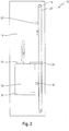
- FIG. 2 shows a schematic view of an elevator safety device 10 according to the present invention.
- a car 26 is movable in an elevator shaft 14 in a vertical direction.
- the elevator safety device 10 comprises a car safety brake device 16 that is adapted to stop the car 26 in the elevator shaft 14.
- the elevator safety device 10 comprises a speed limiter 18 that is adapted to actuate the car safety brake device 16 by using a speed limiter revolution belt being spanned by pulleys around which it recirculates.
- the speed limiter revolution element is formed as a belt 20 having a substantially rectangular cross section. Further at least one abutment element 22 fastened to the speed limiter belt 20 which is formed here in a triangular shape and is attached to and exclusively at the external back side of the belt 20.
- a stopping device 24 and below the car 26 are attached.
- the stopping device 24 at the roof is combined with a car-door as the maintenance entrance for the stuff to enter the shaft. Opening said maintenance door means to automatically actuate the stopping device for defining a shortened moving path for the car relative to the top end of the shaft.
- the stopping device can be automatically activated upon detection of a person stepping on the car roof.
- the stopping device 24 and the second stopping device 32 are respectively switchable between an opened position, to allow a movement of the speed limiter belt 20 and to allow the at least one abutment element 22 to pass the stopping device 24 or the second stopping device 32, and a closed position, to block a movement of speed limiter belt 20 by cooperation of the stopping device 24 or the second stopping device 32 with said abutment element 22.
- Figure 2 shows the second stopping device 32 in an opened, i.e. non-activated position.
- FIG. 3 shows the elevator safety device 10 of Fig. 2 in a position in which the safety device is triggered.
- the stopping device 24 is in a closed position, i.e. activated position so that a movement of speed limiter belt 20 by cooperation of the stopping device 24 with the abutment element 22 is blocked as soon as the abutment element hits the stopping device.
- the safety brake device 16 is actuated by the speed limiter 18 and a safety space 12 is implemented above the car 26 so that a service personnel can work on the roof 28 of the car 26 without any risk. It has to be noted that for the service personnel it is thereby possible to visually check if the stopping device 24 is switched into the closed position to block the movement of the speed limiter belt 20 by cooperation of the stopping device 24 with the abutment element 22.
- FIG. 4 shows a further schematic view of an elevator safety device 10 according the present invention, wherein the second stopping device 32 is in a closed position and wherein a movement of speed limiter belt 20 by cooperation of the second stopping device 32 with the abutment element 22 is blocked.
- the safety brake device 16 is actuated by the speed limiter 18, a safety space 12 is implemented below the car 26 and service personnel can work below the car 26 without any risk.
- Fig. 3 it has to be noted that for the service personnel standing below the car 26 it is thereby possible to visually check if the second stopping device 32 is switched into the closed position to block the movement of the speed limiter belt 20 by cooperation of the second stopping device 32 with the abutment element 22.
- the safety level is significantly increased.
- FIGs 5a and 5b show a schematic comparison of a car 26 comprising balustrades 30 in a folding position and in a operating position.
- the balustrades 30 are arranged at the roof 28 of the car 26 and are the balustrades 30 are collapsible between a folding position and an operating position.
- the balustrades 30 are collapsed in the folding position.
- Figure 5b shows the balustrades 30 in the operating position.
- the stopping device 24 (not shown) is switchable from the opened position to the closed position by collapsing the balustrades 30 into the operating position.
Landscapes
- Maintenance And Inspection Apparatuses For Elevators (AREA)
Claims (13)
- Dispositif de sécurité d'ascenseur (10) destiné à mettre en oeuvre un espace de sécurité (12) dans une cage d'ascenseur (14) ayant une cabine mobile dans la cage d'ascenseur, le dispositif de sécurité d'ascenseur (10) comprenant :un moyen de frein de sécurité de cabine (16) adapté pour arrêter une cabine dans la cage d'ascenseur (14),un limiteur de vitesse (18) adapté pour actionner le moyen de frein de sécurité de cabine (16) en utilisant un élément de transformation de limiteur de vitesse qui est porté par des poulies autour desquelles il est remis en circulation,au moins un élément de butée (22) fixé à l'élément de transformation de limiteur de vitesse, etune unité d'actionnement comprenant au moins un moyen d'arrêt (24) qui peut commuter entre une position ouverte, pour permettre un déplacement de l'élément de transformation de limiteur de vitesse et pour permettre à l'au moins un élément de butée (22) de franchir le moyen d'arrêt (24), et une position fermée, pour bloquer un déplacement de l'élément de transformation de limiteur de vitesse par la coopération du moyen d'arrêt (24) avec ledit élément de butée (22),caractérisé en ce que l'élément de transformation de limiteur de vitesse est une courroie (20) ayant une coupe transversale sensiblement rectangulaire.
- Dispositif de sécurité d'ascenseur (10) selon la revendication 1, caractérisé en ce que l'au moins un élément de butée (22) est attaché exclusivement au côté arrière externe de la courroie (20).
- Dispositif de sécurité d'ascenseur (10) selon la revendication 1 ou 2, caractérisé en ce que le moyen d'arrêt (24) peut être attaché à une cabine (26).
- Dispositif de sécurité d'ascenseur (10) selon la revendication 3, caractérisé en ce que le moyen d'arrêt (24) est adapté pour être combiné à une porte d'inspection située au niveau d'un toit d'une cabine, permettant au moyen d'arrêt (24) de commuter automatiquement lors de l'ouverture de la porte d'inspection afin d'entrer dans l'espace au-dessus de la cabine (26).
- Dispositif de sécurité d'ascenseur (10) selon la revendication 1, caractérisé en ce que la commutation du moyen d'arrêt (24) dans une position fermée est activée lors de la détection d'une personne entrant dans la cage d'ascenseur (14) au-dessus ou en dessous de la cabine d'ascenseur.
- Dispositif de sécurité d'ascenseur (10) selon une quelconque des revendications précédentes, caractérisé en ce que le moyen d'arrêt (24) peut être commuté mécaniquement.
- Dispositif de sécurité d'ascenseur (10) selon une quelconque des revendications précédentes, caractérisé en ce que le moyen d'arrêt (24) peut être commuté à l'aide de solénoïdes.
- Dispositif de sécurité d'ascenseur (10) selon une quelconque des revendications précédentes, caractérisé en ce que le dispositif de sécurité d'ascenseur (10) comprend une cabine (26) qui a des balustrades (30) agencées au niveau d'un toit (28) de la cabine (26).
- Dispositif de sécurité d'ascenseur (10) selon la revendication 8, caractérisé en ce que les balustrades (30) peuvent être pliées entre une position de pliage et une position de fonctionnement, le moyen d'arrêt (24) pouvant être commuté de la position ouverte dans la position fermée en pliant les balustrades (30) dans la position de fonctionnement.
- Dispositif de sécurité d'ascenseur (10) selon une quelconque des revendications précédentes, caractérisé en ce que le dispositif de sécurité d'ascenseur (10) comprend un second moyen d'arrêt (32) attaché à une extrémité inférieure de la cabine (26).
- Dispositif de sécurité d'ascenseur (10) selon une quelconque des revendications précédentes, caractérisé en ce que le limiteur de vitesse (18) est un régulateur de survitesse amenant la courroie du limiteur de vitesse (20) à travers une circonférence d'une poulie.
- Dispositif de sécurité d'ascenseur (10) selon une quelconque des revendications précédentes, caractérisé en ce que l'élément de butée (22) est formé dans une forme triangulaire ou rectangulaire.
- Ascenseur ayant une cabine d'ascenseur mobile à l'intérieur d'une cage d'ascenseur et un dispositif de sécurité d'ascenseur (10) selon une des revendications 1 à 12.
Priority Applications (1)
| Application Number | Priority Date | Filing Date | Title |
|---|---|---|---|
| EP15189115.7A EP3153446B1 (fr) | 2015-10-09 | 2015-10-09 | Dispositif de sécurité d'ascenseur |
Applications Claiming Priority (1)
| Application Number | Priority Date | Filing Date | Title |
|---|---|---|---|
| EP15189115.7A EP3153446B1 (fr) | 2015-10-09 | 2015-10-09 | Dispositif de sécurité d'ascenseur |
Publications (2)
| Publication Number | Publication Date |
|---|---|
| EP3153446A1 EP3153446A1 (fr) | 2017-04-12 |
| EP3153446B1 true EP3153446B1 (fr) | 2018-10-03 |
Family
ID=54291181
Family Applications (1)
| Application Number | Title | Priority Date | Filing Date |
|---|---|---|---|
| EP15189115.7A Active EP3153446B1 (fr) | 2015-10-09 | 2015-10-09 | Dispositif de sécurité d'ascenseur |
Country Status (1)
| Country | Link |
|---|---|
| EP (1) | EP3153446B1 (fr) |
Families Citing this family (2)
| Publication number | Priority date | Publication date | Assignee | Title |
|---|---|---|---|---|
| CN111108053B (zh) * | 2017-09-27 | 2021-07-27 | 因温特奥股份公司 | 安全的电梯井道和轿厢顶部访问 |
| WO2019135018A1 (fr) * | 2018-01-02 | 2019-07-11 | Kone Corporation | Ascenseur doté d'un agencement de dispositif de sécurité |
Family Cites Families (3)
| Publication number | Priority date | Publication date | Assignee | Title |
|---|---|---|---|---|
| JP4673574B2 (ja) | 2003-05-07 | 2011-04-20 | インベンテイオ・アクテイエンゲゼルシヤフト | 一時的保護スペースを供給するための装置を用いたエレベータ設備、該装置の実装方法、および一時的保護スペースを供給するための方法 |
| ES2253981B1 (es) * | 2004-05-10 | 2007-06-16 | Orona, S. Coop. | Cable y cinta para limitador de velocidad de ascensores y poleas asociadas. |
| EP1799602A1 (fr) * | 2004-09-29 | 2007-06-27 | Otis Elevator Company | Dispositif d'arret de surete d'une cabine d'ascenseur |
-
2015
- 2015-10-09 EP EP15189115.7A patent/EP3153446B1/fr active Active
Non-Patent Citations (1)
| Title |
|---|
| None * |
Also Published As
| Publication number | Publication date |
|---|---|
| EP3153446A1 (fr) | 2017-04-12 |
Similar Documents
| Publication | Publication Date | Title |
|---|---|---|
| US8967050B2 (en) | Train platform safety device | |
| CN108217360B (zh) | 电梯安全系统和操作电梯系统的方法 | |
| US10837215B2 (en) | Zone object detection system for elevator system | |
| CN107848745B (zh) | 升降机系统的安全装置 | |
| KR102566855B1 (ko) | 엘리베이터 오버런 시스템 | |
| US10124987B2 (en) | Elevator device | |
| EP3153446B1 (fr) | Dispositif de sécurité d'ascenseur | |
| AU2017232232A1 (en) | Method for avoiding unwanted safety gear tripping in an elevator system, controller adapted to perform such a method, governor brake and elevator system each having such a controller | |
| US20210371241A1 (en) | Elevator safety monitoring system, elevator system, elevator drive unit, and method for operating an elevator | |
| EP1701905B1 (fr) | Ensemble ascenseur | |
| US7137484B2 (en) | Safety system for restraining movement of elevator car when car doors are open | |
| KR20170113868A (ko) | 에스컬레이터 역주행 방지장치 | |
| EP4095081A1 (fr) | Systèmes d'ascenseur | |
| KR20140083505A (ko) | 승강기 안전장치 | |
| EP2495208A1 (fr) | Système de levage | |
| KR20170070617A (ko) | 에스컬레이터 역주행 방지장치 | |
| EP4217300A1 (fr) | Dispositif de commande pour un système d'ascenseur | |
| WO2016174487A1 (fr) | Système de surveillance pour système d'ascenseur pour assurer un espacement de cage d'ascenseur prédéterminé | |
| EP2741990B1 (fr) | Détection et surveillance d'accès à la cuvette inférieure | |
| KR102265012B1 (ko) | 가변속도 엘리베이터의 강제 감속 제어장치 및 방법 | |
| KR100420027B1 (ko) | 엘리베이터 조속기용 링크구조 | |
| ES2652370B1 (es) | Aparato elevador y método de funcionamiento de dicho aparato elevador | |
| Mohite et al. | A review paper on major & minor causes of accidents in elevators in metro city | |
| JP2011063420A (ja) | エレベータ制御装置 | |
| JP4905002B2 (ja) | エレベータの乗場敷居装置 |
Legal Events
| Date | Code | Title | Description |
|---|---|---|---|
| PUAI | Public reference made under article 153(3) epc to a published international application that has entered the european phase |
Free format text: ORIGINAL CODE: 0009012 |
|
| AK | Designated contracting states |
Kind code of ref document: A1 Designated state(s): AL AT BE BG CH CY CZ DE DK EE ES FI FR GB GR HR HU IE IS IT LI LT LU LV MC MK MT NL NO PL PT RO RS SE SI SK SM TR |
|
| AX | Request for extension of the european patent |
Extension state: BA ME |
|
| 17P | Request for examination filed |
Effective date: 20171011 |
|
| RBV | Designated contracting states (corrected) |
Designated state(s): AL AT BE BG CH CY CZ DE DK EE ES FI FR GB GR HR HU IE IS IT LI LT LU LV MC MK MT NL NO PL PT RO RS SE SI SK SM TR |
|
| GRAP | Despatch of communication of intention to grant a patent |
Free format text: ORIGINAL CODE: EPIDOSNIGR1 |
|
| GRAJ | Information related to disapproval of communication of intention to grant by the applicant or resumption of examination proceedings by the epo deleted |
Free format text: ORIGINAL CODE: EPIDOSDIGR1 |
|
| INTG | Intention to grant announced |
Effective date: 20180405 |
|
| RAP1 | Party data changed (applicant data changed or rights of an application transferred) |
Owner name: KONE CORPORATION |
|
| INTC | Intention to grant announced (deleted) | ||
| GRAP | Despatch of communication of intention to grant a patent |
Free format text: ORIGINAL CODE: EPIDOSNIGR1 |
|
| INTG | Intention to grant announced |
Effective date: 20180614 |
|
| GRAS | Grant fee paid |
Free format text: ORIGINAL CODE: EPIDOSNIGR3 |
|
| GRAA | (expected) grant |
Free format text: ORIGINAL CODE: 0009210 |
|
| AK | Designated contracting states |
Kind code of ref document: B1 Designated state(s): AL AT BE BG CH CY CZ DE DK EE ES FI FR GB GR HR HU IE IS IT LI LT LU LV MC MK MT NL NO PL PT RO RS SE SI SK SM TR |
|
| REG | Reference to a national code |
Ref country code: GB Ref legal event code: FG4D |
|
| REG | Reference to a national code |
Ref country code: CH Ref legal event code: EP Ref country code: AT Ref legal event code: REF Ref document number: 1048360 Country of ref document: AT Kind code of ref document: T Effective date: 20181015 |
|
| REG | Reference to a national code |
Ref country code: FR Ref legal event code: PLFP Year of fee payment: 4 |
|
| REG | Reference to a national code |
Ref country code: IE Ref legal event code: FG4D Ref country code: DE Ref legal event code: R096 Ref document number: 602015017398 Country of ref document: DE |
|
| REG | Reference to a national code |
Ref country code: NL Ref legal event code: MP Effective date: 20181003 |
|
| REG | Reference to a national code |
Ref country code: LT Ref legal event code: MG4D |
|
| REG | Reference to a national code |
Ref country code: AT Ref legal event code: MK05 Ref document number: 1048360 Country of ref document: AT Kind code of ref document: T Effective date: 20181003 |
|
| PG25 | Lapsed in a contracting state [announced via postgrant information from national office to epo] |
Ref country code: NL Free format text: LAPSE BECAUSE OF FAILURE TO SUBMIT A TRANSLATION OF THE DESCRIPTION OR TO PAY THE FEE WITHIN THE PRESCRIBED TIME-LIMIT Effective date: 20181003 |
|
| PG25 | Lapsed in a contracting state [announced via postgrant information from national office to epo] |
Ref country code: LV Free format text: LAPSE BECAUSE OF FAILURE TO SUBMIT A TRANSLATION OF THE DESCRIPTION OR TO PAY THE FEE WITHIN THE PRESCRIBED TIME-LIMIT Effective date: 20181003 Ref country code: AT Free format text: LAPSE BECAUSE OF FAILURE TO SUBMIT A TRANSLATION OF THE DESCRIPTION OR TO PAY THE FEE WITHIN THE PRESCRIBED TIME-LIMIT Effective date: 20181003 Ref country code: HR Free format text: LAPSE BECAUSE OF FAILURE TO SUBMIT A TRANSLATION OF THE DESCRIPTION OR TO PAY THE FEE WITHIN THE PRESCRIBED TIME-LIMIT Effective date: 20181003 Ref country code: NO Free format text: LAPSE BECAUSE OF FAILURE TO SUBMIT A TRANSLATION OF THE DESCRIPTION OR TO PAY THE FEE WITHIN THE PRESCRIBED TIME-LIMIT Effective date: 20190103 Ref country code: CZ Free format text: LAPSE BECAUSE OF FAILURE TO SUBMIT A TRANSLATION OF THE DESCRIPTION OR TO PAY THE FEE WITHIN THE PRESCRIBED TIME-LIMIT Effective date: 20181003 Ref country code: PL Free format text: LAPSE BECAUSE OF FAILURE TO SUBMIT A TRANSLATION OF THE DESCRIPTION OR TO PAY THE FEE WITHIN THE PRESCRIBED TIME-LIMIT Effective date: 20181003 Ref country code: BG Free format text: LAPSE BECAUSE OF FAILURE TO SUBMIT A TRANSLATION OF THE DESCRIPTION OR TO PAY THE FEE WITHIN THE PRESCRIBED TIME-LIMIT Effective date: 20190103 Ref country code: LT Free format text: LAPSE BECAUSE OF FAILURE TO SUBMIT A TRANSLATION OF THE DESCRIPTION OR TO PAY THE FEE WITHIN THE PRESCRIBED TIME-LIMIT Effective date: 20181003 Ref country code: ES Free format text: LAPSE BECAUSE OF FAILURE TO SUBMIT A TRANSLATION OF THE DESCRIPTION OR TO PAY THE FEE WITHIN THE PRESCRIBED TIME-LIMIT Effective date: 20181003 Ref country code: IS Free format text: LAPSE BECAUSE OF FAILURE TO SUBMIT A TRANSLATION OF THE DESCRIPTION OR TO PAY THE FEE WITHIN THE PRESCRIBED TIME-LIMIT Effective date: 20190203 Ref country code: FI Free format text: LAPSE BECAUSE OF FAILURE TO SUBMIT A TRANSLATION OF THE DESCRIPTION OR TO PAY THE FEE WITHIN THE PRESCRIBED TIME-LIMIT Effective date: 20181003 |
|
| PG25 | Lapsed in a contracting state [announced via postgrant information from national office to epo] |
Ref country code: RS Free format text: LAPSE BECAUSE OF FAILURE TO SUBMIT A TRANSLATION OF THE DESCRIPTION OR TO PAY THE FEE WITHIN THE PRESCRIBED TIME-LIMIT Effective date: 20181003 Ref country code: SE Free format text: LAPSE BECAUSE OF FAILURE TO SUBMIT A TRANSLATION OF THE DESCRIPTION OR TO PAY THE FEE WITHIN THE PRESCRIBED TIME-LIMIT Effective date: 20181003 Ref country code: GR Free format text: LAPSE BECAUSE OF FAILURE TO SUBMIT A TRANSLATION OF THE DESCRIPTION OR TO PAY THE FEE WITHIN THE PRESCRIBED TIME-LIMIT Effective date: 20190104 Ref country code: AL Free format text: LAPSE BECAUSE OF FAILURE TO SUBMIT A TRANSLATION OF THE DESCRIPTION OR TO PAY THE FEE WITHIN THE PRESCRIBED TIME-LIMIT Effective date: 20181003 Ref country code: PT Free format text: LAPSE BECAUSE OF FAILURE TO SUBMIT A TRANSLATION OF THE DESCRIPTION OR TO PAY THE FEE WITHIN THE PRESCRIBED TIME-LIMIT Effective date: 20190203 |
|
| REG | Reference to a national code |
Ref country code: BE Ref legal event code: MM Effective date: 20181031 |
|
| PG25 | Lapsed in a contracting state [announced via postgrant information from national office to epo] |
Ref country code: LU Free format text: LAPSE BECAUSE OF NON-PAYMENT OF DUE FEES Effective date: 20181009 |
|
| REG | Reference to a national code |
Ref country code: DE Ref legal event code: R097 Ref document number: 602015017398 Country of ref document: DE |
|
| REG | Reference to a national code |
Ref country code: IE Ref legal event code: MM4A |
|
| PG25 | Lapsed in a contracting state [announced via postgrant information from national office to epo] |
Ref country code: DK Free format text: LAPSE BECAUSE OF FAILURE TO SUBMIT A TRANSLATION OF THE DESCRIPTION OR TO PAY THE FEE WITHIN THE PRESCRIBED TIME-LIMIT Effective date: 20181003 Ref country code: IT Free format text: LAPSE BECAUSE OF FAILURE TO SUBMIT A TRANSLATION OF THE DESCRIPTION OR TO PAY THE FEE WITHIN THE PRESCRIBED TIME-LIMIT Effective date: 20181003 |
|
| PLBE | No opposition filed within time limit |
Free format text: ORIGINAL CODE: 0009261 |
|
| STAA | Information on the status of an ep patent application or granted ep patent |
Free format text: STATUS: NO OPPOSITION FILED WITHIN TIME LIMIT |
|
| PG25 | Lapsed in a contracting state [announced via postgrant information from national office to epo] |
Ref country code: RO Free format text: LAPSE BECAUSE OF FAILURE TO SUBMIT A TRANSLATION OF THE DESCRIPTION OR TO PAY THE FEE WITHIN THE PRESCRIBED TIME-LIMIT Effective date: 20181003 Ref country code: SK Free format text: LAPSE BECAUSE OF FAILURE TO SUBMIT A TRANSLATION OF THE DESCRIPTION OR TO PAY THE FEE WITHIN THE PRESCRIBED TIME-LIMIT Effective date: 20181003 Ref country code: BE Free format text: LAPSE BECAUSE OF NON-PAYMENT OF DUE FEES Effective date: 20181031 Ref country code: MC Free format text: LAPSE BECAUSE OF FAILURE TO SUBMIT A TRANSLATION OF THE DESCRIPTION OR TO PAY THE FEE WITHIN THE PRESCRIBED TIME-LIMIT Effective date: 20181003 Ref country code: SM Free format text: LAPSE BECAUSE OF FAILURE TO SUBMIT A TRANSLATION OF THE DESCRIPTION OR TO PAY THE FEE WITHIN THE PRESCRIBED TIME-LIMIT Effective date: 20181003 Ref country code: EE Free format text: LAPSE BECAUSE OF FAILURE TO SUBMIT A TRANSLATION OF THE DESCRIPTION OR TO PAY THE FEE WITHIN THE PRESCRIBED TIME-LIMIT Effective date: 20181003 |
|
| 26N | No opposition filed |
Effective date: 20190704 |
|
| PG25 | Lapsed in a contracting state [announced via postgrant information from national office to epo] |
Ref country code: SI Free format text: LAPSE BECAUSE OF FAILURE TO SUBMIT A TRANSLATION OF THE DESCRIPTION OR TO PAY THE FEE WITHIN THE PRESCRIBED TIME-LIMIT Effective date: 20181003 Ref country code: IE Free format text: LAPSE BECAUSE OF NON-PAYMENT OF DUE FEES Effective date: 20181009 |
|
| PG25 | Lapsed in a contracting state [announced via postgrant information from national office to epo] |
Ref country code: MT Free format text: LAPSE BECAUSE OF NON-PAYMENT OF DUE FEES Effective date: 20181009 |
|
| PG25 | Lapsed in a contracting state [announced via postgrant information from national office to epo] |
Ref country code: TR Free format text: LAPSE BECAUSE OF FAILURE TO SUBMIT A TRANSLATION OF THE DESCRIPTION OR TO PAY THE FEE WITHIN THE PRESCRIBED TIME-LIMIT Effective date: 20181003 |
|
| PG25 | Lapsed in a contracting state [announced via postgrant information from national office to epo] |
Ref country code: MK Free format text: LAPSE BECAUSE OF NON-PAYMENT OF DUE FEES Effective date: 20181003 Ref country code: HU Free format text: LAPSE BECAUSE OF FAILURE TO SUBMIT A TRANSLATION OF THE DESCRIPTION OR TO PAY THE FEE WITHIN THE PRESCRIBED TIME-LIMIT; INVALID AB INITIO Effective date: 20151009 Ref country code: CY Free format text: LAPSE BECAUSE OF FAILURE TO SUBMIT A TRANSLATION OF THE DESCRIPTION OR TO PAY THE FEE WITHIN THE PRESCRIBED TIME-LIMIT Effective date: 20181003 |
|
| P01 | Opt-out of the competence of the unified patent court (upc) registered |
Effective date: 20230525 |
|
| REG | Reference to a national code |
Ref country code: CH Ref legal event code: U11 Free format text: ST27 STATUS EVENT CODE: U-0-0-U10-U11 (AS PROVIDED BY THE NATIONAL OFFICE) Effective date: 20251101 |
|
| PGFP | Annual fee paid to national office [announced via postgrant information from national office to epo] |
Ref country code: DE Payment date: 20251021 Year of fee payment: 11 |
|
| PGFP | Annual fee paid to national office [announced via postgrant information from national office to epo] |
Ref country code: GB Payment date: 20251022 Year of fee payment: 11 |
|
| PGFP | Annual fee paid to national office [announced via postgrant information from national office to epo] |
Ref country code: FR Payment date: 20251030 Year of fee payment: 11 |
|
| PGFP | Annual fee paid to national office [announced via postgrant information from national office to epo] |
Ref country code: CH Payment date: 20251101 Year of fee payment: 11 |