EP3153465B1 - Reformateur destine a la fabrication d'un gaz de synthese - Google Patents
Reformateur destine a la fabrication d'un gaz de synthese Download PDFInfo
- Publication number
- EP3153465B1 EP3153465B1 EP15400044.2A EP15400044A EP3153465B1 EP 3153465 B1 EP3153465 B1 EP 3153465B1 EP 15400044 A EP15400044 A EP 15400044A EP 3153465 B1 EP3153465 B1 EP 3153465B1
- Authority
- EP
- European Patent Office
- Prior art keywords
- gas
- channels
- firebox
- ceiling
- reformer
- Prior art date
- Legal status (The legal status is an assumption and is not a legal conclusion. Google has not performed a legal analysis and makes no representation as to the accuracy of the status listed.)
- Active
Links
Images


Classifications
-
- C—CHEMISTRY; METALLURGY
- C01—INORGANIC CHEMISTRY
- C01B—NON-METALLIC ELEMENTS; COMPOUNDS THEREOF; METALLOIDS OR COMPOUNDS THEREOF NOT COVERED BY SUBCLASS C01C
- C01B3/00—Hydrogen; Gaseous mixtures containing hydrogen; Separation of hydrogen from mixtures containing it; Purification of hydrogen; Reversible storage of hydrogen
- C01B3/02—Production of hydrogen; Production of gaseous mixtures containing hydrogen
- C01B3/32—Production of hydrogen; Production of gaseous mixtures containing hydrogen by reaction of gaseous or liquid organic compounds with gasifying agents, e.g. water, carbon dioxide or air
- C01B3/34—Production of hydrogen; Production of gaseous mixtures containing hydrogen by reaction of gaseous or liquid organic compounds with gasifying agents, e.g. water, carbon dioxide or air by reaction of hydrocarbons with gasifying agents
- C01B3/38—Production of hydrogen; Production of gaseous mixtures containing hydrogen by reaction of gaseous or liquid organic compounds with gasifying agents, e.g. water, carbon dioxide or air by reaction of hydrocarbons with gasifying agents using catalysts
-
- B—PERFORMING OPERATIONS; TRANSPORTING
- B01—PHYSICAL OR CHEMICAL PROCESSES OR APPARATUS IN GENERAL
- B01J—CHEMICAL OR PHYSICAL PROCESSES, e.g. CATALYSIS OR COLLOID CHEMISTRY; THEIR RELEVANT APPARATUS
- B01J8/00—Chemical or physical processes in general, conducted in the presence of fluids and solid particles; Apparatus for such processes
- B01J8/02—Chemical or physical processes in general, conducted in the presence of fluids and solid particles; Apparatus for such processes with stationary particles, e.g. in fixed beds
- B01J8/06—Chemical or physical processes in general, conducted in the presence of fluids and solid particles; Apparatus for such processes with stationary particles, e.g. in fixed beds in tube reactors; the solid particles being arranged in tubes
- B01J8/062—Chemical or physical processes in general, conducted in the presence of fluids and solid particles; Apparatus for such processes with stationary particles, e.g. in fixed beds in tube reactors; the solid particles being arranged in tubes being installed in a furnace
-
- C—CHEMISTRY; METALLURGY
- C01—INORGANIC CHEMISTRY
- C01B—NON-METALLIC ELEMENTS; COMPOUNDS THEREOF; METALLOIDS OR COMPOUNDS THEREOF NOT COVERED BY SUBCLASS C01C
- C01B3/00—Hydrogen; Gaseous mixtures containing hydrogen; Separation of hydrogen from mixtures containing it; Purification of hydrogen; Reversible storage of hydrogen
- C01B3/02—Production of hydrogen; Production of gaseous mixtures containing hydrogen
- C01B3/32—Production of hydrogen; Production of gaseous mixtures containing hydrogen by reaction of gaseous or liquid organic compounds with gasifying agents, e.g. water, carbon dioxide or air
- C01B3/34—Production of hydrogen; Production of gaseous mixtures containing hydrogen by reaction of gaseous or liquid organic compounds with gasifying agents, e.g. water, carbon dioxide or air by reaction of hydrocarbons with gasifying agents
- C01B3/38—Production of hydrogen; Production of gaseous mixtures containing hydrogen by reaction of gaseous or liquid organic compounds with gasifying agents, e.g. water, carbon dioxide or air by reaction of hydrocarbons with gasifying agents using catalysts
- C01B3/384—Production of hydrogen; Production of gaseous mixtures containing hydrogen by reaction of gaseous or liquid organic compounds with gasifying agents, e.g. water, carbon dioxide or air by reaction of hydrocarbons with gasifying agents using catalysts with external heating of the catalyst
-
- C—CHEMISTRY; METALLURGY
- C01—INORGANIC CHEMISTRY
- C01B—NON-METALLIC ELEMENTS; COMPOUNDS THEREOF; METALLOIDS OR COMPOUNDS THEREOF NOT COVERED BY SUBCLASS C01C
- C01B2203/00—Integrated processes for the production of hydrogen or synthesis gas
- C01B2203/02—Processes for making hydrogen or synthesis gas
- C01B2203/0205—Processes for making hydrogen or synthesis gas containing a reforming step
- C01B2203/0227—Processes for making hydrogen or synthesis gas containing a reforming step containing a catalytic reforming step
- C01B2203/0233—Processes for making hydrogen or synthesis gas containing a reforming step containing a catalytic reforming step the reforming step being a steam reforming step
-
- C—CHEMISTRY; METALLURGY
- C01—INORGANIC CHEMISTRY
- C01B—NON-METALLIC ELEMENTS; COMPOUNDS THEREOF; METALLOIDS OR COMPOUNDS THEREOF NOT COVERED BY SUBCLASS C01C
- C01B2203/00—Integrated processes for the production of hydrogen or synthesis gas
- C01B2203/08—Methods of heating or cooling
- C01B2203/0805—Methods of heating the process for making hydrogen or synthesis gas
- C01B2203/0811—Methods of heating the process for making hydrogen or synthesis gas by combustion of fuel
- C01B2203/0816—Heating by flames
-
- C—CHEMISTRY; METALLURGY
- C01—INORGANIC CHEMISTRY
- C01B—NON-METALLIC ELEMENTS; COMPOUNDS THEREOF; METALLOIDS OR COMPOUNDS THEREOF NOT COVERED BY SUBCLASS C01C
- C01B2203/00—Integrated processes for the production of hydrogen or synthesis gas
- C01B2203/12—Feeding the process for making hydrogen or synthesis gas
- C01B2203/1205—Composition of the feed
- C01B2203/1211—Organic compounds or organic mixtures used in the process for making hydrogen or synthesis gas
- C01B2203/1235—Hydrocarbons
Definitions
- the invention further relates to a process for the catalytic conversion of hydrocarbon-containing gas with steam into a synthesis gas containing hydrogen and carbon oxides.
- WO 2013/087194 describes a portable reformer with a large number of horizontal smoke gas tunnels arranged parallel to each other below the firing chamber.
- the construction of this reformer aims to enable the reformer's portability.
- the American filing US 2007/0234974 A1 shows a reformer with flue gas ducts, the cross section of which increases from start to end in order to keep the gas velocity constant over the length of the duct and thus the suction conditions over the width of the reformer housing.
- 7 of this document shows a flue gas duct with a wedge-shaped longitudinal profile.
- FIGS. 6 and 9 show how the openings for the gas passage between the burner chamber of the reformer and the respective flue gas duct are formed by distances between the cover stones of the flue duct.
- the ratio between the dynamic and the static portion of the pressure also remains constant, according to the Bernoulli principle of energy conservation. If, on the other hand, the flow velocity increased from the beginning of the duct to the beginning of the duct, this increase in the dynamic pressure component would decrease the static pressure component and thus increase the static pressure difference between the interior of the reformer housing and the duct. This in turn would tend to lead to a stronger extraction of burner exhaust gas in this area of the channels, which would have to be countered by reducing the passage openings between the housing and the channel.
- Reforming conditions are understood to mean the operating conditions of the reformer system which are known per se to the person skilled in the art and which guarantee a technically and economically sensible degree of conversion of the starting materials to synthesis gas components.
- a set of operating conditions selected for this is also referred to as an operating point.
- the openings in the channel ceilings are continuous over the entire channel length and have a wedge profile that tapers in the direction of flow.
- the aforementioned preferred embodiment can advantageously be combined with flue gas ducts which have a wedge-shaped longitudinal profile, since in this way the change in the duct cross section and the change in the size of the openings in the duct ceilings between the reformer housing and duct take place continuously and without jumps, which makes the exhaust gas flow even of the burner exhaust gas from the reformer housing.
- a further preferred embodiment of the invention is characterized in that the ceilings of the ducts each consist of a plurality of plates running over the entire width of the duct, openings being formed in the duct ceilings by the plates being laid at intervals from one another and the intervals being of the plates become smaller and smaller in the flow direction of the exhaust gas. In this way, the width of the channel opening is maintained over the entire length of the channel. This simplifies the construction and construction of the ducts. The size of the passage openings can be changed in a simple manner by exchanging and / or moving the plates.
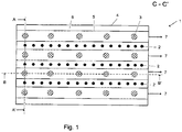
- Fig. 1 shows a steam reformer 1 with reformer tubes 2 arranged in three parallel rows. Parallel to the reformer tube rows, the burners 3 are arranged in four rows in the roof of the steam reformer housing 4.
- a channel 5 for discharging the burner exhaust gas is installed below the bottom 6 of the reformer housing 4 opposite the firing rows.
- the upper limit, ie the cover 11 of the channel 5 also forms part of the bottom 6 of the reformer housing 4.
- the arrows 7 show the direction of flow of the burner exhaust gas.
- the burner exhaust gas when it emerges at the end of the channel 5, is taken over by an exhaust gas collection system, not shown, which comprises a suction device.
- Fig. 2 shows the steam reformer 1 seen from the front.
- the arrows 8 represent the fuel gas supply to the burners 3.
- the flames of the burners 3a are directed vertically into the reformer housing 4.
- the arrows 9 represent the feed gas feed to the reformer tubes 2 and the arrows 10 the product gas discharge from the reformer tubes 2.
- the burner exhaust gas 7 passes through the reformer base 6 through passages in the channel cover 11, here symbolized by a broken line, into the exhaust gas channels 5.
- Fig. 3 shows the steam reformer 1 seen from the long side. This figure outlines how the height H, and thus the cross section, of the channel 5 increases according to the invention from the channel start 5a to the channel end 5b.
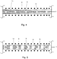
- Fig. 4 corresponds to a section Fig. 1 and shows a burner exhaust gas duct 6 lying between two rows of reformer tubes 2.
- the opening of the duct cover 11 is covered with a grating and the shape of the opening has a wedge profile that is continuous over the entire duct length and tapers in the direction of flow.
- Fig. 5 also corresponds to a section Fig. 1 and also shows a burner exhaust gas duct 6 lying between two rows of reformer tubes 2.
- the cover of the duct consists of a plurality of plates 12 which run over the entire width of the duct and which are laid at intervals from one another on the duct ceiling covered with grating, in such a way that the distances between the plates, and thus the openings in the duct ceiling, continuously decrease from the beginning of the duct to the end of the duct, i.e. in the direction of flow of the burner gases.
- the invention serves to improve the uniformity of the heating of a steam reformer. This increases the efficiency of the reformer operation.
- the invention is therefore industrially applicable.
Landscapes
- Chemical & Material Sciences (AREA)
- Chemical Kinetics & Catalysis (AREA)
- Organic Chemistry (AREA)
- Health & Medical Sciences (AREA)
- General Health & Medical Sciences (AREA)
- Engineering & Computer Science (AREA)
- Combustion & Propulsion (AREA)
- Inorganic Chemistry (AREA)
- Hydrogen, Water And Hydrids (AREA)
- Fuel Cell (AREA)
Claims (4)
- Reformeur à la vapeur (1) comprenant :- une enceinte de chauffe (4) avec un plancher (6), un plafond et des parois latérales délimitant l'enceinte de chauffe (4),- des tubes de catalyseur (2) agencés en plusieurs rangées, qui passent à travers le plancher (6) et/ou le plafond de l'enceinte de chauffe,- des brûleurs (3) agencés dans le plafond, le plancher ou une ou plusieurs parois latérales de l'enceinte de chauffe pour chauffer les tubes de catalyseur (2),- des canalisations d'amenée s'étendant sous le plancher (6) ou au-dessus du plafond de l'enceinte de chauffe (4) pour l'alimentation des tubes de catalyseur en gaz éduit (9) et du brûleur (3) en air et en gaz combustible,- des canalisations de collecte s'étendant sous le plancher (6) ou au-dessus du plafond de l'enceinte de chauffe (4), pour l'évacuation du gaz produit (10),- des canaux s'étendant sous le plancher (6) ou au-dessus du plafond de l'enceinte de chauffe (4), pour évacuer les gaz d'échappement de brûleur (7) hors de l'enceinte de chauffe (4), dans lequel les canaux présentent un profil longitudinal cunéiforme qui s'élargît dans la direction d'écoulement de son début (5a) à son extrémité (5b), et dans lequel les plafonds ou les planchers des canaux sont formés chacun par le plancher ou le plafond de l'enceinte de chauffe (4), dans lequel les canaux sont agencés longitudinalement et entre les rangées de tubes de catalyseur (2), et dans lequel les plafonds des canaux présentent des ouvertures pour le passage des gaz d'échappement (7),caractérisé en ce que
les canaux pour évacuer les gaz d'échappement de brûleur sont conçus pour que la vitesse d'écoulement des gaz d'échappement de brûleur soit constante sur toute la longueur des canaux, et prévus perpendiculaires aux tubes de catalyseur, et en ce que les ouvertures dans les plafonds de canal soient recouvertes de caillebotis. - Reformeur à la vapeur (1) selon la revendication 1, caractérisé en ce que les ouvertures (11) situées dans les plafonds de canal sont continues sur toute la longueur de canal, et présentent ainsi un profil cunéiforme qui est effilé dans la direction d'écoulement.
- Reformeur à la vapeur (1) selon l'une des revendications précédentes, caractérisé en ce que les plafonds des canaux sont constitués d'une pluralité de plaques (12) s'étendant sur toute la largeur des canaux, dans lequel des ouvertures sont formées dans les plafonds de canal, dans lesquelles les plaques (12) sont disposés à distance les unes des autres, et dans lequel les ouvertures dans les plafonds de canal diminuent de manière continue dans la direction d'écoulement.
- Procédé de conversion catalytique d'un gaz hydrocarboné avec de la vapeur en un gaz de synthèse contenant de l'hydrogène et des oxydes de carbone, comprenant les étapes de procédé consistant à :- fournir un gaz hydrocarboné et de la vapeur,- produire un gaz éduit en mélangeant le gaz et la vapeur,- convertir le gaz éduit en un gaz de synthèse comprenant de l'hydrogène et des oxydes de carbone par réaction dans un reformeur à la vapeur selon l'une des revendications 1 à 3 dans des conditions de reformage,- évacuer le gaz de synthèse pour un traitement ultérieur en dehors du procédé.
Priority Applications (6)
| Application Number | Priority Date | Filing Date | Title |
|---|---|---|---|
| EP15400044.2A EP3153465B1 (fr) | 2015-10-05 | 2015-10-05 | Reformateur destine a la fabrication d'un gaz de synthese |
| DE102015117573.8A DE102015117573A1 (de) | 2015-10-05 | 2015-10-15 | Reformer zur Erzeugung von Synthesegas |
| US15/765,884 US10773230B2 (en) | 2015-10-05 | 2016-09-28 | Reformer for producing synthesis gas having improved burner waste gas flow |
| PCT/EP2016/025104 WO2017059962A1 (fr) | 2015-10-05 | 2016-09-28 | Reformeur pour la production d'un gaz de synthèse |
| CN201610888418.XA CN106938838B (zh) | 2015-10-05 | 2016-09-30 | 用于生产合成气体的重整炉 |
| CN201621114395.9U CN206767645U (zh) | 2015-10-05 | 2016-09-30 | 用于生产合成气体的重整炉 |
Applications Claiming Priority (1)
| Application Number | Priority Date | Filing Date | Title |
|---|---|---|---|
| EP15400044.2A EP3153465B1 (fr) | 2015-10-05 | 2015-10-05 | Reformateur destine a la fabrication d'un gaz de synthese |
Publications (2)
| Publication Number | Publication Date |
|---|---|
| EP3153465A1 EP3153465A1 (fr) | 2017-04-12 |
| EP3153465B1 true EP3153465B1 (fr) | 2020-01-01 |
Family
ID=54541004
Family Applications (1)
| Application Number | Title | Priority Date | Filing Date |
|---|---|---|---|
| EP15400044.2A Active EP3153465B1 (fr) | 2015-10-05 | 2015-10-05 | Reformateur destine a la fabrication d'un gaz de synthese |
Country Status (5)
| Country | Link |
|---|---|
| US (1) | US10773230B2 (fr) |
| EP (1) | EP3153465B1 (fr) |
| CN (2) | CN106938838B (fr) |
| DE (1) | DE102015117573A1 (fr) |
| WO (1) | WO2017059962A1 (fr) |
Families Citing this family (2)
| Publication number | Priority date | Publication date | Assignee | Title |
|---|---|---|---|---|
| EP3153465B1 (fr) * | 2015-10-05 | 2020-01-01 | L'Air Liquide Société Anonyme pour l'Etude et l'Exploitation des Procédés Georges Claude | Reformateur destine a la fabrication d'un gaz de synthese |
| ES2941038T3 (es) | 2019-11-13 | 2023-05-16 | Air Liquide | Horno reformador para llevar a cabo un proceso endotérmico |
Family Cites Families (34)
| Publication number | Priority date | Publication date | Assignee | Title |
|---|---|---|---|---|
| US2028326A (en) * | 1931-01-23 | 1936-01-21 | Standard Oil Dev Co | Apparatus for the production of hydrogen |
| US3334971A (en) * | 1964-08-18 | 1967-08-08 | Chemical Construction Corp | Catalytically reforming hydrocarbon and steam mixtures |
| US3424695A (en) * | 1965-09-28 | 1969-01-28 | Peter Von Wiesenthal | Improving reformer-furnace performance by using gas-turbine exhaust |
| US3882826A (en) | 1974-05-22 | 1975-05-13 | Lummus Co | Flue gas distributor and radiator for uniform heat transfer |
| US4198385A (en) * | 1976-09-07 | 1980-04-15 | Waagner-Biro Aktiengesellschaft | Reduction of sodium sulfate to sodium sulfide |
| US4108119A (en) * | 1977-01-19 | 1978-08-22 | Mcwhorter Edward Milton | Bottom cycle manifold for four-stroke internal combustion engines |
| US6134879A (en) * | 1989-12-21 | 2000-10-24 | United Technologies Corporation | Suppression system for a gas turbine engine |
| US5417731A (en) * | 1993-09-14 | 1995-05-23 | Owens-Brockway Glass Container, Inc. | Method of heating a charge, including injecting secondary oxidant into the output port |
| AU687930B2 (en) * | 1993-12-23 | 1998-03-05 | John Stuart Fleming | Flammable fluid fuelled heater |
| DE19512219C1 (de) * | 1995-03-22 | 1996-04-04 | Mannesmann Ag | Anlage zur indirekten Übertragung von Wärme auf ein Prozeßmedium |
| US6303092B1 (en) * | 1995-04-10 | 2001-10-16 | Air Products And Chemicals, Inc. | Process for operating equilibrium controlled reactions |
| JP3495509B2 (ja) * | 1996-06-19 | 2004-02-09 | 三菱重工業株式会社 | 水蒸気改質炉の燃焼ガス排出ダクト |
| JP2001249065A (ja) * | 1999-12-28 | 2001-09-14 | Ono Sokki Co Ltd | 排出ガス希釈装置 |
| JP4815668B2 (ja) * | 2000-05-15 | 2011-11-16 | トヨタ自動車株式会社 | 水素生成装置 |
| EP1193219B1 (fr) * | 2000-09-20 | 2005-08-24 | Air Products And Chemicals, Inc. | Dispositif et procédé pour le reformage d' hydrocarbure |
| JP2003288934A (ja) * | 2002-01-23 | 2003-10-10 | Nissan Motor Co Ltd | 燃料電池用燃料改質装置 |
| US6844637B1 (en) * | 2003-08-13 | 2005-01-18 | Curtiss-Wright Electro-Mechanical Corporation | Rotor assembly end turn cooling system and method |
| US7833009B2 (en) * | 2004-09-10 | 2010-11-16 | Air Products And Chemicals, Inc. | Oxidant injection method |
| DE102005020943A1 (de) * | 2005-05-04 | 2006-11-09 | Linde Ag | Verfahren und Reaktor zur Durchführung endothermer katalytischer Reaktionen |
| US7504048B2 (en) * | 2005-06-14 | 2009-03-17 | Air Products And Chemicals, Inc. | Axial convective reformer |
| US7686611B2 (en) * | 2005-11-03 | 2010-03-30 | Air Products And Chemicals, Inc. | Flame straightening in a furnace |
| US20070234974A1 (en) * | 2006-04-10 | 2007-10-11 | The Cust-O-Fab Companies, Llc | Fired heater and flue gas tunnel therefor |
| CN100439697C (zh) * | 2007-01-19 | 2008-12-03 | 合肥工业大学 | 具有燃料重整机构的柴油机排放系统 |
| FR2914396A1 (fr) * | 2007-03-30 | 2008-10-03 | Inst Francais Du Petrole | Nouveau four de vaporeformage utilisant des bruleurs poreux |
| MX2011013913A (es) * | 2009-06-24 | 2012-02-23 | Thyssenkrupp Uhde Gmbh | Reformador primario para la formacion reducida de oxido nitrico. |
| US8545213B2 (en) * | 2010-03-09 | 2013-10-01 | Air Products And Chemicals, Inc. | Reformer and method of operating the reformer |
| AU2011316891B2 (en) * | 2010-10-22 | 2013-09-19 | Lanzatech Nz, Inc. | Methods and systems for the production of hydrocarbon products |
| CN103619753A (zh) * | 2011-06-27 | 2014-03-05 | 气体产品与化学公司 | 操作催化蒸汽-烃重整器的方法 |
| US20130074515A1 (en) * | 2011-09-23 | 2013-03-28 | General Electric Company | Gas turbine engine system and method of providing a fuel supplied to one or more combustors in a gas turbine engine system |
| DE102011120938A1 (de) * | 2011-12-14 | 2013-06-20 | Thyssenkrupp Uhde Gmbh | Transportabler Reformer |
| EP2708812B1 (fr) * | 2012-09-13 | 2017-08-02 | L'AIR LIQUIDE, Société Anonyme pour l'Etude et l'Exploitation des Procédés Georges Claude | Procédé et appareil pour réactions endothermiques |
| US9272905B2 (en) * | 2014-02-27 | 2016-03-01 | Honeywell International, Inc. | Method for optimizing down fired reforming furnaces |
| US9958211B2 (en) * | 2015-03-12 | 2018-05-01 | Bayotech, Inc. | Nested-flow heat exchangers and chemical reactors |
| EP3153465B1 (fr) * | 2015-10-05 | 2020-01-01 | L'Air Liquide Société Anonyme pour l'Etude et l'Exploitation des Procédés Georges Claude | Reformateur destine a la fabrication d'un gaz de synthese |
-
2015
- 2015-10-05 EP EP15400044.2A patent/EP3153465B1/fr active Active
- 2015-10-15 DE DE102015117573.8A patent/DE102015117573A1/de not_active Withdrawn
-
2016
- 2016-09-28 WO PCT/EP2016/025104 patent/WO2017059962A1/fr not_active Ceased
- 2016-09-28 US US15/765,884 patent/US10773230B2/en active Active
- 2016-09-30 CN CN201610888418.XA patent/CN106938838B/zh not_active Expired - Fee Related
- 2016-09-30 CN CN201621114395.9U patent/CN206767645U/zh not_active Withdrawn - After Issue
Non-Patent Citations (1)
| Title |
|---|
| None * |
Also Published As
| Publication number | Publication date |
|---|---|
| CN106938838B (zh) | 2021-12-14 |
| US10773230B2 (en) | 2020-09-15 |
| WO2017059962A1 (fr) | 2017-04-13 |
| US20180296998A1 (en) | 2018-10-18 |
| DE102015117573A1 (de) | 2017-04-06 |
| CN106938838A (zh) | 2017-07-11 |
| EP3153465A1 (fr) | 2017-04-12 |
| CN206767645U (zh) | 2017-12-19 |
Similar Documents
| Publication | Publication Date | Title |
|---|---|---|
| WO2006117136A1 (fr) | Procede et reacteur pour effectuer des reactions catalytiques endothermiques | |
| DE2439144B2 (de) | Vorrichtung zum Verteilen strömender Medien von einem Strömungsquerschnitt auf einen davon verschiedenen Strömungsquerschnitt | |
| EP2791052B1 (fr) | Reformeur transportable | |
| EP3153465B1 (fr) | Reformateur destine a la fabrication d'un gaz de synthese | |
| DE4221837C1 (en) | Shrouded catalytic reformer tube - with partially enclosed gas mixing zone, for prodn. of synthesis gas | |
| DE2147802A1 (fr) | ||
| DE2616085C2 (fr) | ||
| EP0427828B1 (fr) | Chambre de chauffage dans des fours a coke et procede de chauffage | |
| EP3068529A1 (fr) | Procédé et dispositif de reformage à la vapeur et de clivage à la vapeur d'hydrocarbures | |
| DE2203420A1 (de) | Verfahren und Einrichtung zum Erhitzen eines stroemenden Mediums | |
| DE10333854A1 (de) | Röhrenspaltofen | |
| DE1767980A1 (de) | Rohrofen | |
| DE102009030480B3 (de) | Primärreformer zur reduzierten Stickoxidentstehung | |
| EP3153464B1 (fr) | Réformeur à vapeur destiné à la fabrication d'un gaz de synthèse | |
| DE202015105493U1 (de) | Reformer zur Erzeugung von Synthesegas | |
| DE19955892C2 (de) | Vorrichtung zur Reformierung eines Kohlenwasserstoffs mit langkettigen Kohlenwasserstoffanteilen | |
| EP3821973A1 (fr) | Four de reformage permettant de mettre en uvre un processus endothermique | |
| DE102014004091A1 (de) | Dampfreformer | |
| DE220576C (fr) | ||
| DE102016014907A1 (de) | Wärmetauscher mit Brenner | |
| AT255632B (de) | Ofen | |
| DE102015121037A1 (de) | Vorrichtung zur Sauerstoffverteilung in einem Oxidationsreaktor, Oxidationsreaktor und Anlage mit einer solchen Vorrichtung und Betriebsverfahren | |
| DE102013205871A1 (de) | Strömungsleitelement und Hochtemperaturbrennstoffzellenvorrichtung | |
| DE1230964B (de) | Ofen fuer eine Wasserdampfreformiervorrichtung | |
| EP0369556A2 (fr) | Procédé et dispositif de chauffage indirect d'un courant de gaz dans un espace de réaction pour une réaction endothermique |
Legal Events
| Date | Code | Title | Description |
|---|---|---|---|
| PUAI | Public reference made under article 153(3) epc to a published international application that has entered the european phase |
Free format text: ORIGINAL CODE: 0009012 |
|
| STAA | Information on the status of an ep patent application or granted ep patent |
Free format text: STATUS: THE APPLICATION HAS BEEN PUBLISHED |
|
| AK | Designated contracting states |
Kind code of ref document: A1 Designated state(s): AL AT BE BG CH CY CZ DE DK EE ES FI FR GB GR HR HU IE IS IT LI LT LU LV MC MK MT NL NO PL PT RO RS SE SI SK SM TR |
|
| AX | Request for extension of the european patent |
Extension state: BA ME |
|
| STAA | Information on the status of an ep patent application or granted ep patent |
Free format text: STATUS: REQUEST FOR EXAMINATION WAS MADE |
|
| 17P | Request for examination filed |
Effective date: 20170608 |
|
| RBV | Designated contracting states (corrected) |
Designated state(s): AL AT BE BG CH CY CZ DE DK EE ES FI FR GB GR HR HU IE IS IT LI LT LU LV MC MK MT NL NO PL PT RO RS SE SI SK SM TR |
|
| STAA | Information on the status of an ep patent application or granted ep patent |
Free format text: STATUS: EXAMINATION IS IN PROGRESS |
|
| 17Q | First examination report despatched |
Effective date: 20190226 |
|
| RIC1 | Information provided on ipc code assigned before grant |
Ipc: B01J 8/06 20060101ALI20190528BHEP Ipc: C01B 3/38 20060101AFI20190528BHEP |
|
| GRAP | Despatch of communication of intention to grant a patent |
Free format text: ORIGINAL CODE: EPIDOSNIGR1 |
|
| STAA | Information on the status of an ep patent application or granted ep patent |
Free format text: STATUS: GRANT OF PATENT IS INTENDED |
|
| INTG | Intention to grant announced |
Effective date: 20190816 |
|
| GRAS | Grant fee paid |
Free format text: ORIGINAL CODE: EPIDOSNIGR3 |
|
| GRAA | (expected) grant |
Free format text: ORIGINAL CODE: 0009210 |
|
| STAA | Information on the status of an ep patent application or granted ep patent |
Free format text: STATUS: THE PATENT HAS BEEN GRANTED |
|
| AK | Designated contracting states |
Kind code of ref document: B1 Designated state(s): AL AT BE BG CH CY CZ DE DK EE ES FI FR GB GR HR HU IE IS IT LI LT LU LV MC MK MT NL NO PL PT RO RS SE SI SK SM TR |
|
| REG | Reference to a national code |
Ref country code: GB Ref legal event code: FG4D Free format text: NOT ENGLISH |
|
| REG | Reference to a national code |
Ref country code: CH Ref legal event code: EP Ref country code: AT Ref legal event code: REF Ref document number: 1219576 Country of ref document: AT Kind code of ref document: T Effective date: 20200115 |
|
| REG | Reference to a national code |
Ref country code: DE Ref legal event code: R096 Ref document number: 502015011381 Country of ref document: DE |
|
| REG | Reference to a national code |
Ref country code: IE Ref legal event code: FG4D Free format text: LANGUAGE OF EP DOCUMENT: GERMAN |
|
| REG | Reference to a national code |
Ref country code: NL Ref legal event code: FP |
|
| REG | Reference to a national code |
Ref country code: LT Ref legal event code: MG4D |
|
| PG25 | Lapsed in a contracting state [announced via postgrant information from national office to epo] |
Ref country code: CZ Free format text: LAPSE BECAUSE OF FAILURE TO SUBMIT A TRANSLATION OF THE DESCRIPTION OR TO PAY THE FEE WITHIN THE PRESCRIBED TIME-LIMIT Effective date: 20200101 Ref country code: LT Free format text: LAPSE BECAUSE OF FAILURE TO SUBMIT A TRANSLATION OF THE DESCRIPTION OR TO PAY THE FEE WITHIN THE PRESCRIBED TIME-LIMIT Effective date: 20200101 Ref country code: PT Free format text: LAPSE BECAUSE OF FAILURE TO SUBMIT A TRANSLATION OF THE DESCRIPTION OR TO PAY THE FEE WITHIN THE PRESCRIBED TIME-LIMIT Effective date: 20200527 Ref country code: RS Free format text: LAPSE BECAUSE OF FAILURE TO SUBMIT A TRANSLATION OF THE DESCRIPTION OR TO PAY THE FEE WITHIN THE PRESCRIBED TIME-LIMIT Effective date: 20200101 Ref country code: FI Free format text: LAPSE BECAUSE OF FAILURE TO SUBMIT A TRANSLATION OF THE DESCRIPTION OR TO PAY THE FEE WITHIN THE PRESCRIBED TIME-LIMIT Effective date: 20200101 Ref country code: NO Free format text: LAPSE BECAUSE OF FAILURE TO SUBMIT A TRANSLATION OF THE DESCRIPTION OR TO PAY THE FEE WITHIN THE PRESCRIBED TIME-LIMIT Effective date: 20200401 |
|
| PG25 | Lapsed in a contracting state [announced via postgrant information from national office to epo] |
Ref country code: IS Free format text: LAPSE BECAUSE OF FAILURE TO SUBMIT A TRANSLATION OF THE DESCRIPTION OR TO PAY THE FEE WITHIN THE PRESCRIBED TIME-LIMIT Effective date: 20200501 Ref country code: BG Free format text: LAPSE BECAUSE OF FAILURE TO SUBMIT A TRANSLATION OF THE DESCRIPTION OR TO PAY THE FEE WITHIN THE PRESCRIBED TIME-LIMIT Effective date: 20200401 Ref country code: GR Free format text: LAPSE BECAUSE OF FAILURE TO SUBMIT A TRANSLATION OF THE DESCRIPTION OR TO PAY THE FEE WITHIN THE PRESCRIBED TIME-LIMIT Effective date: 20200402 Ref country code: LV Free format text: LAPSE BECAUSE OF FAILURE TO SUBMIT A TRANSLATION OF THE DESCRIPTION OR TO PAY THE FEE WITHIN THE PRESCRIBED TIME-LIMIT Effective date: 20200101 Ref country code: SE Free format text: LAPSE BECAUSE OF FAILURE TO SUBMIT A TRANSLATION OF THE DESCRIPTION OR TO PAY THE FEE WITHIN THE PRESCRIBED TIME-LIMIT Effective date: 20200101 Ref country code: HR Free format text: LAPSE BECAUSE OF FAILURE TO SUBMIT A TRANSLATION OF THE DESCRIPTION OR TO PAY THE FEE WITHIN THE PRESCRIBED TIME-LIMIT Effective date: 20200101 |
|
| REG | Reference to a national code |
Ref country code: DE Ref legal event code: R097 Ref document number: 502015011381 Country of ref document: DE |
|
| PG25 | Lapsed in a contracting state [announced via postgrant information from national office to epo] |
Ref country code: DK Free format text: LAPSE BECAUSE OF FAILURE TO SUBMIT A TRANSLATION OF THE DESCRIPTION OR TO PAY THE FEE WITHIN THE PRESCRIBED TIME-LIMIT Effective date: 20200101 Ref country code: ES Free format text: LAPSE BECAUSE OF FAILURE TO SUBMIT A TRANSLATION OF THE DESCRIPTION OR TO PAY THE FEE WITHIN THE PRESCRIBED TIME-LIMIT Effective date: 20200101 Ref country code: EE Free format text: LAPSE BECAUSE OF FAILURE TO SUBMIT A TRANSLATION OF THE DESCRIPTION OR TO PAY THE FEE WITHIN THE PRESCRIBED TIME-LIMIT Effective date: 20200101 Ref country code: SM Free format text: LAPSE BECAUSE OF FAILURE TO SUBMIT A TRANSLATION OF THE DESCRIPTION OR TO PAY THE FEE WITHIN THE PRESCRIBED TIME-LIMIT Effective date: 20200101 Ref country code: RO Free format text: LAPSE BECAUSE OF FAILURE TO SUBMIT A TRANSLATION OF THE DESCRIPTION OR TO PAY THE FEE WITHIN THE PRESCRIBED TIME-LIMIT Effective date: 20200101 Ref country code: SK Free format text: LAPSE BECAUSE OF FAILURE TO SUBMIT A TRANSLATION OF THE DESCRIPTION OR TO PAY THE FEE WITHIN THE PRESCRIBED TIME-LIMIT Effective date: 20200101 |
|
| PLBE | No opposition filed within time limit |
Free format text: ORIGINAL CODE: 0009261 |
|
| STAA | Information on the status of an ep patent application or granted ep patent |
Free format text: STATUS: NO OPPOSITION FILED WITHIN TIME LIMIT |
|
| 26N | No opposition filed |
Effective date: 20201002 |
|
| PG25 | Lapsed in a contracting state [announced via postgrant information from national office to epo] |
Ref country code: PL Free format text: LAPSE BECAUSE OF FAILURE TO SUBMIT A TRANSLATION OF THE DESCRIPTION OR TO PAY THE FEE WITHIN THE PRESCRIBED TIME-LIMIT Effective date: 20200101 Ref country code: SI Free format text: LAPSE BECAUSE OF FAILURE TO SUBMIT A TRANSLATION OF THE DESCRIPTION OR TO PAY THE FEE WITHIN THE PRESCRIBED TIME-LIMIT Effective date: 20200101 |
|
| REG | Reference to a national code |
Ref country code: CH Ref legal event code: PL |
|
| PG25 | Lapsed in a contracting state [announced via postgrant information from national office to epo] |
Ref country code: LU Free format text: LAPSE BECAUSE OF NON-PAYMENT OF DUE FEES Effective date: 20201005 Ref country code: MC Free format text: LAPSE BECAUSE OF FAILURE TO SUBMIT A TRANSLATION OF THE DESCRIPTION OR TO PAY THE FEE WITHIN THE PRESCRIBED TIME-LIMIT Effective date: 20200101 |
|
| PG25 | Lapsed in a contracting state [announced via postgrant information from national office to epo] |
Ref country code: CH Free format text: LAPSE BECAUSE OF NON-PAYMENT OF DUE FEES Effective date: 20201031 Ref country code: LI Free format text: LAPSE BECAUSE OF NON-PAYMENT OF DUE FEES Effective date: 20201031 |
|
| PG25 | Lapsed in a contracting state [announced via postgrant information from national office to epo] |
Ref country code: IE Free format text: LAPSE BECAUSE OF NON-PAYMENT OF DUE FEES Effective date: 20201005 |
|
| REG | Reference to a national code |
Ref country code: AT Ref legal event code: MM01 Ref document number: 1219576 Country of ref document: AT Kind code of ref document: T Effective date: 20201005 |
|
| PG25 | Lapsed in a contracting state [announced via postgrant information from national office to epo] |
Ref country code: AT Free format text: LAPSE BECAUSE OF NON-PAYMENT OF DUE FEES Effective date: 20201005 |
|
| PG25 | Lapsed in a contracting state [announced via postgrant information from national office to epo] |
Ref country code: TR Free format text: LAPSE BECAUSE OF FAILURE TO SUBMIT A TRANSLATION OF THE DESCRIPTION OR TO PAY THE FEE WITHIN THE PRESCRIBED TIME-LIMIT Effective date: 20200101 Ref country code: MT Free format text: LAPSE BECAUSE OF FAILURE TO SUBMIT A TRANSLATION OF THE DESCRIPTION OR TO PAY THE FEE WITHIN THE PRESCRIBED TIME-LIMIT Effective date: 20200101 Ref country code: CY Free format text: LAPSE BECAUSE OF FAILURE TO SUBMIT A TRANSLATION OF THE DESCRIPTION OR TO PAY THE FEE WITHIN THE PRESCRIBED TIME-LIMIT Effective date: 20200101 |
|
| PG25 | Lapsed in a contracting state [announced via postgrant information from national office to epo] |
Ref country code: MK Free format text: LAPSE BECAUSE OF FAILURE TO SUBMIT A TRANSLATION OF THE DESCRIPTION OR TO PAY THE FEE WITHIN THE PRESCRIBED TIME-LIMIT Effective date: 20200101 Ref country code: AL Free format text: LAPSE BECAUSE OF FAILURE TO SUBMIT A TRANSLATION OF THE DESCRIPTION OR TO PAY THE FEE WITHIN THE PRESCRIBED TIME-LIMIT Effective date: 20200101 |
|
| P01 | Opt-out of the competence of the unified patent court (upc) registered |
Effective date: 20230518 |
|
| PGFP | Annual fee paid to national office [announced via postgrant information from national office to epo] |
Ref country code: IT Payment date: 20231020 Year of fee payment: 9 Ref country code: FR Payment date: 20231026 Year of fee payment: 9 |
|
| PG25 | Lapsed in a contracting state [announced via postgrant information from national office to epo] |
Ref country code: FR Free format text: LAPSE BECAUSE OF NON-PAYMENT OF DUE FEES Effective date: 20241031 |
|
| PG25 | Lapsed in a contracting state [announced via postgrant information from national office to epo] |
Ref country code: IT Free format text: LAPSE BECAUSE OF NON-PAYMENT OF DUE FEES Effective date: 20241005 |
|
| PGFP | Annual fee paid to national office [announced via postgrant information from national office to epo] |
Ref country code: NL Payment date: 20251021 Year of fee payment: 11 |
|
| PGFP | Annual fee paid to national office [announced via postgrant information from national office to epo] |
Ref country code: DE Payment date: 20251021 Year of fee payment: 11 |
|
| PGFP | Annual fee paid to national office [announced via postgrant information from national office to epo] |
Ref country code: GB Payment date: 20251022 Year of fee payment: 11 |
|
| PGFP | Annual fee paid to national office [announced via postgrant information from national office to epo] |
Ref country code: BE Payment date: 20251021 Year of fee payment: 11 |