EP3153629B1 - Entraînement pivotant hydraulique et dispositif de préhension comprenant un tel entraînement pivotant - Google Patents
Entraînement pivotant hydraulique et dispositif de préhension comprenant un tel entraînement pivotant Download PDFInfo
- Publication number
- EP3153629B1 EP3153629B1 EP16190135.0A EP16190135A EP3153629B1 EP 3153629 B1 EP3153629 B1 EP 3153629B1 EP 16190135 A EP16190135 A EP 16190135A EP 3153629 B1 EP3153629 B1 EP 3153629B1
- Authority
- EP
- European Patent Office
- Prior art keywords
- cross
- piston
- pistons
- piston running
- drive according
- Prior art date
- Legal status (The legal status is an assumption and is not a legal conclusion. Google has not performed a legal analysis and makes no representation as to the accuracy of the status listed.)
- Not-in-force
Links
- 238000007789 sealing Methods 0.000 claims description 12
- 238000010276 construction Methods 0.000 description 3
- 238000005192 partition Methods 0.000 description 3
- 230000009467 reduction Effects 0.000 description 3
- 238000006243 chemical reaction Methods 0.000 description 2
- 238000006073 displacement reaction Methods 0.000 description 2
- 230000000694 effects Effects 0.000 description 2
- 239000012530 fluid Substances 0.000 description 2
- 230000002706 hydrostatic effect Effects 0.000 description 2
- 230000007704 transition Effects 0.000 description 2
- 230000006978 adaptation Effects 0.000 description 1
- 230000008901 benefit Effects 0.000 description 1
- 210000000078 claw Anatomy 0.000 description 1
- 230000001419 dependent effect Effects 0.000 description 1
- 230000001627 detrimental effect Effects 0.000 description 1
- 230000002349 favourable effect Effects 0.000 description 1
- 230000003993 interaction Effects 0.000 description 1
- 239000000463 material Substances 0.000 description 1
- 230000002093 peripheral effect Effects 0.000 description 1
- 239000007787 solid Substances 0.000 description 1
- 230000007480 spreading Effects 0.000 description 1
Images


Classifications
-
- F—MECHANICAL ENGINEERING; LIGHTING; HEATING; WEAPONS; BLASTING
- F15—FLUID-PRESSURE ACTUATORS; HYDRAULICS OR PNEUMATICS IN GENERAL
- F15B—SYSTEMS ACTING BY MEANS OF FLUIDS IN GENERAL; FLUID-PRESSURE ACTUATORS, e.g. SERVOMOTORS; DETAILS OF FLUID-PRESSURE SYSTEMS, NOT OTHERWISE PROVIDED FOR
- F15B15/00—Fluid-actuated devices for displacing a member from one position to another; Gearing associated therewith
- F15B15/02—Mechanical layout characterised by the means for converting the movement of the fluid-actuated element into movement of the finally-operated member
- F15B15/06—Mechanical layout characterised by the means for converting the movement of the fluid-actuated element into movement of the finally-operated member for mechanically converting rectilinear movement into non- rectilinear movement
- F15B15/068—Mechanical layout characterised by the means for converting the movement of the fluid-actuated element into movement of the finally-operated member for mechanically converting rectilinear movement into non- rectilinear movement the motor being of the helical type
-
- B—PERFORMING OPERATIONS; TRANSPORTING
- B66—HOISTING; LIFTING; HAULING
- B66C—CRANES; LOAD-ENGAGING ELEMENTS OR DEVICES FOR CRANES, CAPSTANS, WINCHES, OR TACKLES
- B66C3/00—Load-engaging elements or devices attached to lifting or lowering gear of cranes or adapted for connection therewith and intended primarily for transmitting lifting forces to loose materials; Grabs
- B66C3/005—Grab supports, e.g. articulations; Oscillation dampers; Orientation
-
- B—PERFORMING OPERATIONS; TRANSPORTING
- B66—HOISTING; LIFTING; HAULING
- B66C—CRANES; LOAD-ENGAGING ELEMENTS OR DEVICES FOR CRANES, CAPSTANS, WINCHES, OR TACKLES
- B66C3/00—Load-engaging elements or devices attached to lifting or lowering gear of cranes or adapted for connection therewith and intended primarily for transmitting lifting forces to loose materials; Grabs
- B66C3/14—Grabs opened or closed by driving motors thereon
- B66C3/16—Grabs opened or closed by driving motors thereon by fluid motors
-
- E—FIXED CONSTRUCTIONS
- E02—HYDRAULIC ENGINEERING; FOUNDATIONS; SOIL SHIFTING
- E02F—DREDGING; SOIL-SHIFTING
- E02F3/00—Dredgers; Soil-shifting machines
- E02F3/04—Dredgers; Soil-shifting machines mechanically-driven
- E02F3/28—Dredgers; Soil-shifting machines mechanically-driven with digging tools mounted on a dipper- or bucket-arm, i.e. there is either one arm or a pair of arms, e.g. dippers, buckets
- E02F3/36—Component parts
- E02F3/40—Dippers; Buckets ; Grab devices, e.g. manufacturing processes for buckets, form, geometry or material of buckets
- E02F3/413—Dippers; Buckets ; Grab devices, e.g. manufacturing processes for buckets, form, geometry or material of buckets with grabbing device
-
- E—FIXED CONSTRUCTIONS
- E02—HYDRAULIC ENGINEERING; FOUNDATIONS; SOIL SHIFTING
- E02F—DREDGING; SOIL-SHIFTING
- E02F9/00—Component parts of dredgers or soil-shifting machines, not restricted to one of the kinds covered by groups E02F3/00 - E02F7/00
- E02F9/006—Pivot joint assemblies
-
- F—MECHANICAL ENGINEERING; LIGHTING; HEATING; WEAPONS; BLASTING
- F16—ENGINEERING ELEMENTS AND UNITS; GENERAL MEASURES FOR PRODUCING AND MAINTAINING EFFECTIVE FUNCTIONING OF MACHINES OR INSTALLATIONS; THERMAL INSULATION IN GENERAL
- F16H—GEARING
- F16H25/00—Gearings comprising primarily only cams, cam-followers and screw-and-nut mechanisms
- F16H25/18—Gearings comprising primarily only cams, cam-followers and screw-and-nut mechanisms for conveying or interconverting oscillating or reciprocating motions
- F16H25/20—Screw mechanisms
- F16H2025/2028—Screw mechanisms using screw profiles with high efficiency for converting reciprocating motion into oscillating movement
-
- F—MECHANICAL ENGINEERING; LIGHTING; HEATING; WEAPONS; BLASTING
- F16—ENGINEERING ELEMENTS AND UNITS; GENERAL MEASURES FOR PRODUCING AND MAINTAINING EFFECTIVE FUNCTIONING OF MACHINES OR INSTALLATIONS; THERMAL INSULATION IN GENERAL
- F16H—GEARING
- F16H25/00—Gearings comprising primarily only cams, cam-followers and screw-and-nut mechanisms
- F16H25/18—Gearings comprising primarily only cams, cam-followers and screw-and-nut mechanisms for conveying or interconverting oscillating or reciprocating motions
- F16H25/20—Screw mechanisms
- F16H2025/2059—Common movement by two screws or two nuts, e.g. two connected screws with opposite thread direction
-
- F—MECHANICAL ENGINEERING; LIGHTING; HEATING; WEAPONS; BLASTING
- F16—ENGINEERING ELEMENTS AND UNITS; GENERAL MEASURES FOR PRODUCING AND MAINTAINING EFFECTIVE FUNCTIONING OF MACHINES OR INSTALLATIONS; THERMAL INSULATION IN GENERAL
- F16H—GEARING
- F16H25/00—Gearings comprising primarily only cams, cam-followers and screw-and-nut mechanisms
- F16H25/18—Gearings comprising primarily only cams, cam-followers and screw-and-nut mechanisms for conveying or interconverting oscillating or reciprocating motions
- F16H25/20—Screw mechanisms
Definitions
- the present invention relates to a hydraulic rotary actuator for a gripper having two forceps-like movable gripping arms or shells, with two rotatably mounted in a drive housing, mutually parallel pivot shafts whose shaft ends are connectable to the gripping arms or shells, wherein the pivot shafts each two have opposing ffereningriffsabête with which two by means of hydraulic pressure counter-movable piston for driving the pivot shafts are in threaded engagement.
- a pivot drive for a clamshell grab is for example from the DE 201 07 206 U1 known, in which the pivot shafts are each part of a hydraulic motor which is enclosed by the shell carrier formed as a closed housing.
- the pivot shafts which open and close the gripping arms or gripping shells, pipe sections are seated, which are longitudinally displaceable, but non-rotatably guided and are in screw engagement with the respective pivot shaft, so that a longitudinal displacement of the pipe sections leads to a rotation of the pivot shafts.
- the longitudinal displacement of the pipe sections is effected by means of a common center piece, which the pipe sections connects and is designed as a piston which is received in the interior of the housing, which forms the cylinder for the piston and can be acted upon by corresponding pressure chambers with hydraulic pressure.
- the DE 20 2006 013 101 U1 proposes to solve the above bearing problems and taming the axial forces before the use of two oppositely traversing pistons, which are in each case with two pivot shafts in screwing, and thereby use opposing ffereningriffabitese the pivot shaft, so that moving apart of the piston and a reverse movement of the piston, the pivot shafts in the one or the other direction twisted.
- the axial bearing pressure can be minimized, since the driving forces and reaction forces of the pistons largely compensate each other.
- the present invention is therefore an object of the invention to provide an improved rotary actuator of the type mentioned, which avoids the disadvantages of the prior art and the latter further develops in an advantageous manner.
- a lighter construction of the drive housing should be achieved without having to compromise on the drive torque of the pivot shafts and the gripping force of gripping to accept.
- each piston is provided with different piston portions, which are adapted to the respective cylinder pressure chamber.
- the pistons each have two outer lateral surface side piston running surfaces, which are differently shaped in cross section and are arranged continuously in different sized and differently shaped cross sections, formed by the drive housing cylinder pressure chambers.
- a piston portion and the associated cylinder pressure chamber can be optimally adapted to the Aufschwenkamba and the other piston portion and the associated cylinder pressure chamber to the Zuschwenk- or accessing movement.
- each piston on both pivot shafts and the associated spatial limitations can be limited and controlled by the sections different contouring of the piston resulting pressure for the housing without this functionally relevant reductions in the drive torque of the pivot shafts and gripping force of the gripper in purchasing to have to take.
- the pistons can be arranged with their respective larger piston running surfaces facing each other, so that the cross-sectional area of the outer pressure chambers, which are to the lateral end walls, in particular housing covers, the drive housing are arranged, is smaller than the cross-sectional area of the at least one, located between the piston inner pressure chamber.
- the pressure forces on said end walls due to the smaller area lower.
- In the larger, lying between the piston pressure chamber such axial forces play no relevant role.
- a common pressure chamber between the pistons there is no partition that would be acted upon axially by the hydraulic pressure. Even if two separate pressure chambers are provided between the pistons and separated by a partition wall, the axial pressures on the said partition compensate each other, since these are then acted upon from opposite sides with corresponding pressures.
- the orientation of the screw engaging portions on the piston and pivot shafts may cooperate with the various pressure chambers such that the smaller pressure chamber, that is smaller in effective cross-sectional area, causes the gripper arms or bowls to pivot on the pivot shafts while, conversely, pivoting together Gripper arms of the larger cylinder pressure chamber cross-section is effected.
- the smaller pressure chamber that is smaller in effective cross-sectional area
- Gripper arms of the larger cylinder pressure chamber cross-section is effected.
- the different contouring of the different piston sections can be adapted to the different sizes of the cross-sectional areas, in particular such that in the cross-sectional area larger cylinder pressure chamber of the piston and cylinder pressure chamber cross-section is less flattened than in the area smaller pressure chambers.
- This is based on the consideration, that in the cross-sectional area larger pressure chambers, the circumference of the piston running surface and thus the circumference of the lateral surface of the cylinder pressure chamber is longer than in the quer4.000s vom adopted smaller pressure chambers, so that the housing wall in the cross section area larger cylinder pressure chamber has a larger area and is therefore subjected to greater radial pressure forces than in the cross section area smaller cylinder pressure chamber.
- said higher radial pressure forces on the housing in the region of the cross-sectional area larger cylinder pressure chamber from the housing wall can be better absorbed than would be the case with a more flattened cross-section, since flattened cross sections under high internal pressures tend to be pressed, that is the short major axis is lengthened while the long main axis is shortened.
- the material of the housing wall can best be exploited by the different cross-sectional contouring in interaction with the different cross-sectional areas and the Radial horrbeetzschung be optimally intercepted with a thin-walled, lightweight construction, although in itself the deviation from the flattened piston contour, the distance from the fact of the two apart Pivoting waves is given, seems unrealistic, because one would expect losses in terms of a small size and thus a higher weight.
- the radial pressure forces have a small spreading effect, when the housing cross-section is less flattened, a weight advantage can be achieved by a thinner wall thickness.
- the less flattened piston portion may have an at least approximately circular cross-sectional contouring.
- the associated cylinder pressure chamber which is preferably the cross-sectional area larger cylinder pressure chamber, then has correspondingly circular cylindrical shape.
- the more flattened piston portion may be oval or elliptical or similarly rounded, with the cylinder pressure chamber in which this oval or elliptical or otherwise rounded piston portion running, has a corresponding oval or elliptical or otherwise rounded cylinder cross-sectional contour.
- the circular cylindrical design of the larger cylinder pressure chamber can best intercept the correspondingly higher radial forces on the cylinder wall, which are worked here with small wall thicknesses and a corresponding weight savings can be achieved if one considers this in comparison to a corresponding flattened cylinder chamber.
- the wall thicknesses of the jacket surface side cylinder pressure chamber walls can be chosen differently, since then the reduction effect of the radial forces occurring due to the cross-sectional area reduction comes more or less to bear.
- the drive housing in a portion between the piston, which limits the cross-sectional area larger pressure chamber have a smaller wall thickness than in a housing portion which limits the outer side pressure chambers lateral surface.
- the same wall thicknesses can be provided in said lateral surface portions, with larger cross-sectional area differences of the pressure chambers is also considered to thin the wall thickness of the housing shell in the lateral, smaller pressure chambers form in the central housing portion which limits the larger pressure chamber mantle surface side.
- the pivot shafts can execute counter-rotating or co-rotating pivoting movements, wherein in particular a counter-rotation of the pivot shaft drive movements can be provided when used as a gripper drive.
- the two pivot shafts may each have two mutually oppositely oriented ffereningriffsabête, which are in threaded engagement with one of the two shaft drive pieces, so that rotation of the pivot shafts in one direction by a collapse the two shaft drive pieces and a rotation of the pivot shafts in the opposite direction is achieved by moving apart of the two shaft drive pieces.
- a turning in one direction or a rotation in the other direction means advantageously not that both shafts rotate in the same direction, but that the two pivot shafts rotate in opposite directions, in particular about a time apart pivoting of the hook shells and the other times to achieve a pivoting together of the claw shells.
- the pistons may preferably have sealing portions arranged towards their mutually facing sides and running on the pivot shafts.
- the pivot shafts may advantageously each have between their counter-rotating screw engagement sections a tooth-free section on which run the aforementioned sealing portions of the piston.
- the said gear-free sections may have a smooth, cylindrical surface and have at least as large a diameter as the screw engagement sections, so that the sealing sections of the pistons can slide precisely on said gear-free sections. As a result, not only stabilize the piston over tilting moments can be achieved, but also a seal of the piston can be achieved on the pivot shafts.
- each piston is advantageously also sealed to the outside, that is to say the inner circumferential surfaces of the cylinder pressure chambers.
- each of the differently contoured Kolbenlauzan each piston has a sealing portion with which the two piston running surfaces of each piston is sealed on the one hand to the lateral surface of the larger cylinder pressure chamber and on the other hand to the lateral surface of the smaller cylinder pressure chamber.
- the slope of the screw engaging portions can basically be chosen differently and on the one hand to be achieved pivot angle of the pivot shafts and the torques to be achieved are adapted to the pivot shafts.
- a favorable compromise for the proposed arrangement of two counter-rotating shaft drive pieces is in a further development of the invention is that the opposite screw engaging portions of the pivot shafts each have a pitch angle in the range of 30 ° to 60 °.
- said pitch angle is between 40 ° and 50 °, wherein it may be about 45 ° in an advantageous embodiment.
- fundamentally different pitch angles are possible, depending on which pivot angle the pivot shafts have to achieve and which torques must be achieved.
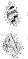
- pivot drive 3 comprises a drive housing 1, which is designed as a shell carrier and can be coupled in a conventional manner to the stem of an excavator or other hoist.
- the drive housing 1 may have on its upper side an annular pivot bearing 2 and a rotary drive associated therewith, not shown in detail, in order to rotate the gripper about an upright axis can.
- the housing 1 comprises two mutually parallel end walls 4 and 5, which are interconnected by an optionally multi-part housing shell 6, so that the end walls 4 and 5 together with the housing shells 6 define an interior space 7.
- the two pivot shafts 8 and 9 are arranged parallel to each other and spaced from each other. They are rotatable in the end walls 4 and 5, but mounted axially fixed in each case by means of a bearing 10 and protrude with their pin-shaped shaft ends 11 out of the housing.
- a bearing 10 mounted axially fixed in each case by means of a bearing 10 and protrude with their pin-shaped shaft ends 11 out of the housing.
- To the Pintle-shaped shaft ends 11 can be rotatably coupled in a conventional manner gripper shells, which are not shown in the drawing, so that the gripper shells by turning the pivot shafts 8 and 9 can be pivoted up and down.
- each piston 12 and 13 inside the drive housing 1 parallel to the pivot shafts 8 and 9 slidably seated.
- the housing 1 forms the cylinders for the shaft drive pieces 12 and 13, to whose two outer sides in each case a pressure chamber 15 and 16 and between which a common pressure chamber 17 or possibly two separate pressure chambers are formed.
- each pivot shaft 8 and 9 has two oppositely formed ringingriffsabête 19 and 20, the fferveriereungen have opposite slopes.
- the two screw engaging portions 19 and 20 advantageously have the same pitch angle in terms of magnitude, which may advantageously be in the range of 30 ° to 60 °, for example 45 °.
- each pivot shaft 8 and 9 has a non-serrated portion 21 which has a smooth cylindrical surface and advantageously may have a slightly larger diameter than the outer diameter of the screw engaging portions 19 and 20.
- the tooth-free portion 21 be offset from the screw engaging portions 19 and 20 by a relief groove 22.
- the spline-free portion 21 could be divided into two subsegments, each associated with one of the screw engaging portions 19 and 20, respectively.
- the two pistons 12 and 13 each have a sealing portion 23 which is also tubular and the respective pivot shaft 8 and 9 surrounds.
- the said seal portions 23 can run on the tooth-free portion 21 of the respective pivot shaft to a guide and a seal of the pistons 12 and 13 with respect to the pivot shafts 8 and 9 to achieve.
- the pistons 12 and 13 are adapted with its outer contour to the defined by the housing 1 inner contour, which forms the cylinders or pressure chambers 15, 16 and 17, and sealed by suitable sealing means.
- each piston 12 and 13 has two differently shaped piston treads 24 and 25 provided on axially different piston portions and corresponding outer circumferential surface portions of the piston 12 or 13 are formed.
- each of the pistons 12 and 13 has a more flattened piston tread 24 and a less flattened piston tread 25, the arrangement of the two piston treads 24 and 25 may advantageously be made such that - viewed in the longitudinal direction of the pivot shafts - the flattened piston tread 24 completely is disposed within the contour of the less flattened piston tread 25.
- the longer main axis of the flattened piston running surface 24 may be even shorter than the corresponding Main axis and / or the diameter of the less flattened piston tread 25, see.
- FIG. 2 shows, each of the pistons 12 and 13 has a more flattened piston tread 24 and a less flattened piston tread 25, the arrangement of the two piston treads 24 and 25 may advantageously be made such that - viewed in the longitudinal direction of the pivot shafts - the flattened piston tread 24 completely is disposed within the contour of the less flattened piston tread 25.
- the longer main axis of the flattened piston running surface 24 may be even shorter than the corresponding Main axis and
- the less flattened piston tread 25 be contoured at least approximately circular, while - regardless of a circular or not exactly circular contouring of said flattened less piston portion 25 - the flattened piston tread advantageously have oval or elliptical or similarly rounded peripheral contour can, cf. FIG. 2 ,
- the longer main axis of the cross section of the flattened piston running surface 25 extends parallel to a connecting straight line through the two pivot shafts 8 and 9, while the shorter main axis of the cross section of the flattened piston running surface 24 perpendicular to one of the two pivot shafts 8 and 9 connect Plane extends.
- the less flattened piston tread 25 is not contoured exactly circular on the circumference, but also slightly flattened, the longer and shorter major axes of the cross-sectional contour of the less flattened piston tread 25 may be aligned in a corresponding manner.
- each of the pistons 12 and 13 in the region between said piston tread 24 and 25 have a tapered contour, so that the respective piston 12 and 13 does not form a right-angled step between the two piston treads 24 and 25, see.
- FIG. 2 shows,
- FIG. 1 shows the mantle surface side walls of the drive housing 1 in the region of the lateral, outer pressure chambers 15 and 16 oval or elliptical or similarly rounded contoured, so that said pressure chambers 15 and 16 have an oval, elliptical or similarly rounded cylindrical shape.
- FIGS. 1 . 7 and 8 show, between the circular cylindrical, inner pressure chamber 17 and the lateral, outer pressure chambers 15 and 16 a beveled lateral surface transition on the housing shell 6 is provided, cf.
- a bevel may be provided at an angle of about 45 ° to a plane which is perpendicular to the pivot shaft longitudinal axes.
- other chamfer angles and / or rounded chamfer transitions may also be provided.
Landscapes
- Engineering & Computer Science (AREA)
- Mechanical Engineering (AREA)
- General Engineering & Computer Science (AREA)
- Mining & Mineral Resources (AREA)
- Civil Engineering (AREA)
- Structural Engineering (AREA)
- Physics & Mathematics (AREA)
- Fluid Mechanics (AREA)
- Actuator (AREA)
Claims (16)
- Entraînement pivotant hydraulique pour un grappin qui possède deux bras ou deux coques de préhension déplaçables à la manière d'une pince, comprenant deux arbres pivotants (8, 9) logés de manière rotative dans un carter d'entraînement (1), parallèles l'un à l'autre, dont les bouts d'arbre (11) peuvent être reliés aux bras de préhension, les arbres pivotants (8, 9) possédant respectivement deux sections de préhension par vissage (19, 20), inverses l'une par rapport à l'autre, avec lesquelles deux pistons (12, 13) déplaçables de manière inverse sont en prise de manière vissée pour entraîner les arbres pivotants (8, 9), caractérisé en ce que les pistons (12, 13) possèdent respectivement deux surfaces de roulement de piston (24, 25) côté surface d'enveloppe extérieure, lesquelles sont formées différemment en section transversale et sont disposées en se déplaçant dans des chambres de pression de cylindre (15, 16 ; 17) de formes différentes en section transversale, réalisées par le carter d'entraînement (1).
- Entraînement pivotant hydraulique selon la revendication précédente, les pistons (12, 13) étant disposés de manière à être tournés l'un vers l'autre avec leurs surfaces de roulement de piston (25) respectivement plus grandes.
- Entraînement pivotant hydraulique selon l'une quelconque des revendications précédentes, les pistons (12, 13) délimitant entre eux au moins une chambre de pression (17), dont la surface de la section transversale est plus grande que la surface de la section transversale des chambres de pression (15, 16) qui sont prévues sur les côtés, détournés l'un vers l'autre, des deux pistons (12, 13).
- Entraînement pivotant hydraulique selon l'une quelconque des revendications précédentes, une surface de roulement de piston (25), des deux dites surfaces de roulement de piston (24, 25) de chaque piston (12, 13), étant, en vue en section transversale, moins aplatie et l'autre surface de roulement de piston (24) étant plus aplatie.
- Entraînement pivotant hydraulique selon la revendication précédente, la surface de roulement de piston (25) moins aplatie possédant une section transversale au moins approximativement circulaire et/ou la surface de roulement de piston (24) plus aplatie possédant une section transversale ovale ou elliptique.
- Entraînement pivotant hydraulique selon l'une quelconque des deux revendications précédentes, le contour de la surface de roulement de piston (24) plus aplatie, en vue en direction longitudinale de l'axe de pivotement, étant entièrement situé à l'intérieur du contour de la surface de roulement de piston (25) moins aplatie, de préférence aussi bien un axe principal plus long et un axe principal plus court de la section transversale de la surface de roulement de piston (24) plus aplatie étant plus petits qu'un diamètre de la surface de roulement de piston (25) moins aplatie ou que les axes principaux plus courts et plus longs de la section transversale des dites surfaces de roulement de piston (25) moins aplaties.
- Entraînement pivotant hydraulique selon l'une quelconque des trois revendications précédentes, la surface de roulement de piston (24) plus aplatie étant orientée de manière à ce qu'un axe principal plus long de la section transversale de cette surface de roulement de piston (24) plus aplatie s'étende parallèlement à un plan de liaison qui relie les deux arbres pivotants (8, 9), et l'axe principal plus court de la section transversale de ladite surface de roulement de piston (24) plus aplatie étant vertical par rapport au dit plan de liaison.
- Entraînement pivotant hydraulique selon l'une quelconque des revendications précédentes, le carter d'entraînement (1) définissant au moins une chambre de pression de cylindre (17) entre les pistons (12, 13) et définissant sur les côtés des pistons (12, 13), détournés l'un de l'autre, deux chambres de pression de cylindre (15, 16) ayant une forme cylindrique divergeant de la forme cylindrique circulaire, notamment ayant une section ovale ou elliptique.
- Entraînement pivotant hydraulique selon l'une quelconque des revendications précédentes, le carter d'entraînement (1) possédant dans la partie de sa surface enveloppante, qui délimite la chambre de pression (17) entre les pistons (2, 13), une autre épaisseur de paroi que dans la partie d'une section, côté surface enveloppante, qui délimite les chambres de pression extérieures (15, 16) sur les côtés des pistons (12, 13), détournés l'un de l'autre.
- Entraînement pivotant hydraulique selon l'une quelconque des revendications précédentes, chaque piston (12, 13) présentant sur chacune de ses surfaces de roulement de piston (24, 25) une section d'étanchéité (27, 28) pour étancher la surface enveloppante, par rapport aux chambres de pression (15, 16 ; 17) plus grandes et plus petites.
- Entraînement pivotant hydraulique selon l'une quelconque des revendications précédentes, chaque piston (12, 13) présentant sur son côté tourné vers l'autre piston respectif (12, 13) une section d'étanchéité d'arbre (23) pour étancher par rapport aux arbres pivotants (8, 9).
- Entraînement pivotant hydraulique selon l'une quelconque des revendications précédentes, les arbres pivotants (8, 9) chacun possédant une section (21) exempte d'engrenage entre leurs sections de prise par vissage (19, 20) inverse.
- Entraînement pivotant hydraulique selon l'une quelconque des deux revendications précédentes, la section (21) exempte d'engrenage formant une section de guidage et/ou d'étanchéité, sur laquelle reposent les sections d'étanchéité (23) des pistons (12, 13) de manière longitudinalement déplaçable.
- Entraînement pivotant hydraulique selon l'une quelconque des revendications précédentes, la surface de roulement de piston (25), qui est plus grand au point de vue de la surface de la section transversale, des pistons (12, 13) possédant une surface de la section transversale située dans la plage de 125% à 300% de la surface de la section transversale de la plus petite surface de roulement de piston (24).
- Entraînement pivotant hydraulique selon l'une quelconque des deux revendications précédentes, les sections de prise par vissage (19, 20) présentant un angle de pas situé dans la plage comprise entre 30° et 60°, de préférence d'environ 40° à 50°.
- Grappin, notamment grappin à deux coques, comprenant un entraînement pivotant hydraulique réalisé selon l'une quelconque des revendications précédentes.
Priority Applications (1)
| Application Number | Priority Date | Filing Date | Title |
|---|---|---|---|
| PL16190135T PL3153629T3 (pl) | 2015-10-06 | 2016-09-22 | Hydrauliczny napęd obrotowy oraz chwytak z takim napędem obrotowym |
Applications Claiming Priority (1)
| Application Number | Priority Date | Filing Date | Title |
|---|---|---|---|
| DE202015006973.8U DE202015006973U1 (de) | 2015-10-06 | 2015-10-06 | Hydraulischer Schwenkantrieb sowie Greifer mit einem solchen Schwenkantrieb |
Publications (2)
| Publication Number | Publication Date |
|---|---|
| EP3153629A1 EP3153629A1 (fr) | 2017-04-12 |
| EP3153629B1 true EP3153629B1 (fr) | 2018-07-25 |
Family
ID=57218667
Family Applications (1)
| Application Number | Title | Priority Date | Filing Date |
|---|---|---|---|
| EP16190135.0A Not-in-force EP3153629B1 (fr) | 2015-10-06 | 2016-09-22 | Entraînement pivotant hydraulique et dispositif de préhension comprenant un tel entraînement pivotant |
Country Status (6)
| Country | Link |
|---|---|
| US (1) | US10066648B2 (fr) |
| EP (1) | EP3153629B1 (fr) |
| AU (1) | AU2016238839A1 (fr) |
| DE (1) | DE202015006973U1 (fr) |
| DK (1) | DK3153629T3 (fr) |
| PL (1) | PL3153629T3 (fr) |
Cited By (1)
| Publication number | Priority date | Publication date | Assignee | Title |
|---|---|---|---|---|
| DE202021103928U1 (de) | 2021-07-23 | 2022-10-25 | Kinshofer Gmbh | Hydraulischer Schwenkantrieb für einen Greifer |
Family Cites Families (10)
| Publication number | Priority date | Publication date | Assignee | Title |
|---|---|---|---|---|
| US3187592A (en) * | 1962-03-14 | 1965-06-08 | Gen Motors Corp | Rotary actuator |
| DE2115707A1 (de) * | 1970-04-18 | 1972-02-03 | Daiei Kogyo Sha Kk | Druckmittelbetriebenes Stellorgan für Drehmomentantriebe |
| US4745847A (en) * | 1987-09-03 | 1988-05-24 | Pneumo Abex Corporation | Helical splined rotary actuator |
| DE20107206U1 (de) * | 2001-04-02 | 2002-08-08 | Kinshofer Greiftechnik GmbH, 83666 Waakirchen | Antriebsvorrichtung für eine Greifeinrichtung |
| US7210720B2 (en) * | 2002-06-28 | 2007-05-01 | 1994 Weyer Family Limited Partnership | Timed rotation tool assembly and actuator |
| DE20319227U1 (de) | 2003-12-11 | 2005-04-21 | Kinshofer Greiftechnik Gmbh & Co. Kg | Hydraulischer Schwenkantrieb für einen Greifer |
| DE202004013158U1 (de) | 2004-08-23 | 2006-01-12 | Kinshofer Greiftechnik Gmbh & Co. Kg | Hydraulischer Schwenkantrieb für einen Greifer |
| DE102005033452A1 (de) * | 2005-07-18 | 2007-01-25 | Kinshofer Greiftechnik Gmbh & Co. Kg | Drehmotor sowie Verfahren zu seiner Herstellung |
| DE202006003589U1 (de) * | 2006-03-07 | 2007-07-19 | Kinshofer Gmbh | Drehmotor |
| DE202006013101U1 (de) | 2006-08-25 | 2008-01-03 | Kinshofer Gmbh | Hydraulischer Schwenkantrieb für einen Greifer |
-
2015
- 2015-10-06 DE DE202015006973.8U patent/DE202015006973U1/de not_active Expired - Lifetime
-
2016
- 2016-09-22 PL PL16190135T patent/PL3153629T3/pl unknown
- 2016-09-22 EP EP16190135.0A patent/EP3153629B1/fr not_active Not-in-force
- 2016-09-22 DK DK16190135.0T patent/DK3153629T3/en active
- 2016-09-30 US US15/283,049 patent/US10066648B2/en not_active Expired - Fee Related
- 2016-09-30 AU AU2016238839A patent/AU2016238839A1/en not_active Abandoned
Non-Patent Citations (1)
| Title |
|---|
| None * |
Cited By (2)
| Publication number | Priority date | Publication date | Assignee | Title |
|---|---|---|---|---|
| DE202021103928U1 (de) | 2021-07-23 | 2022-10-25 | Kinshofer Gmbh | Hydraulischer Schwenkantrieb für einen Greifer |
| EP4134346A1 (fr) | 2021-07-23 | 2023-02-15 | Kinshofer GmbH | Entraînement pivotant hydraulique pour un préhenseur |
Also Published As
| Publication number | Publication date |
|---|---|
| US20170097020A1 (en) | 2017-04-06 |
| DK3153629T3 (en) | 2018-09-17 |
| DE202015006973U1 (de) | 2017-01-10 |
| AU2016238839A1 (en) | 2017-04-20 |
| EP3153629A1 (fr) | 2017-04-12 |
| PL3153629T3 (pl) | 2018-12-31 |
| US10066648B2 (en) | 2018-09-04 |
Similar Documents
| Publication | Publication Date | Title |
|---|---|---|
| EP1991792B1 (fr) | Moteur-couple | |
| EP2218549B1 (fr) | Unité de rotation pour la construction en carrosserie dans l'industrie automobile pour pivoter des composants lourds | |
| DE19500914A1 (de) | Taumelgelenkbeschlag für einen verstellbaren Fahrzeugsitz | |
| EP2004996A1 (fr) | Machine a piston hydrostatique avec disque de commande rotatif | |
| DE2111830B2 (de) | Zweistufige Klemm oder Schließ vorrichtung, insbesondere fur die lineare Schließbewegung von Gieß formhalften | |
| DE2924800A1 (de) | Drosselvorrichtung fuer eine zweiwellige schneckenmaschine | |
| DE2400741A1 (de) | Bandfuehrungsvorrichtung | |
| EP1247005B1 (fr) | Arbre se presentant sous forme de piece mecanique avec des conduites integrees | |
| EP3153629B1 (fr) | Entraînement pivotant hydraulique et dispositif de préhension comprenant un tel entraînement pivotant | |
| DE4335678A1 (de) | Drehvorrichtung für Baggergreifer | |
| DE10044784A1 (de) | Verstellvorrichtung für eine Axialkolbenmaschine in Schrägachsenbauweise | |
| EP1541771B1 (fr) | Entraînement pivotant hydraulique pour benne preneuse | |
| DE60116062T2 (de) | Blockierungssystem für ein drehlager | |
| DE1775222A1 (de) | Hydrostatisches Getriebe | |
| DE10044782C1 (de) | Verstelleinrichtung für eine Axialkolbenmaschine in Schrägachsenbauweise | |
| DE202006013101U1 (de) | Hydraulischer Schwenkantrieb für einen Greifer | |
| DE2101963C3 (de) | Axialkolbenmaschine mit veränderbarem Hubvolumen | |
| DE4237463C2 (de) | Ausgleichsgetriebe | |
| DE2003814A1 (de) | Vorrichtung zur Umsetzung einer geradlinigen Bewegung in eine Drehbewegung um eine Schwenkachse | |
| EP1018416A2 (fr) | Calandre pour matières premières dans l'indutrie de la céramique | |
| CH682988A5 (de) | Anbauschere. | |
| DE202005011280U1 (de) | Hub-/Schwenkvorrichtung für Ladebordwände und/oder -rampen | |
| DE1684037C3 (de) | Beschickungswagen für zur Herstellung keramischer und feuerfester Gegenstände dienende Pressen mit korn- oder pulverförmigen Materialien | |
| WO2019105901A1 (fr) | Moteur à combustion interne et procédé pour faire fonctionner un moteur à combustion interne | |
| DE102017119463A1 (de) | Verbrennungskraftmaschine mit nichtzylindrischen Stützkolben |
Legal Events
| Date | Code | Title | Description |
|---|---|---|---|
| PUAI | Public reference made under article 153(3) epc to a published international application that has entered the european phase |
Free format text: ORIGINAL CODE: 0009012 |
|
| AK | Designated contracting states |
Kind code of ref document: A1 Designated state(s): AL AT BE BG CH CY CZ DE DK EE ES FI FR GB GR HR HU IE IS IT LI LT LU LV MC MK MT NL NO PL PT RO RS SE SI SK SM TR |
|
| AX | Request for extension of the european patent |
Extension state: BA ME |
|
| 17P | Request for examination filed |
Effective date: 20170913 |
|
| RBV | Designated contracting states (corrected) |
Designated state(s): AL AT BE BG CH CY CZ DE DK EE ES FI FR GB GR HR HU IE IS IT LI LT LU LV MC MK MT NL NO PL PT RO RS SE SI SK SM TR |
|
| GRAP | Despatch of communication of intention to grant a patent |
Free format text: ORIGINAL CODE: EPIDOSNIGR1 |
|
| INTG | Intention to grant announced |
Effective date: 20180206 |
|
| GRAS | Grant fee paid |
Free format text: ORIGINAL CODE: EPIDOSNIGR3 |
|
| GRAA | (expected) grant |
Free format text: ORIGINAL CODE: 0009210 |
|
| AK | Designated contracting states |
Kind code of ref document: B1 Designated state(s): AL AT BE BG CH CY CZ DE DK EE ES FI FR GB GR HR HU IE IS IT LI LT LU LV MC MK MT NL NO PL PT RO RS SE SI SK SM TR |
|
| REG | Reference to a national code |
Ref country code: GB Ref legal event code: FG4D Free format text: NOT ENGLISH |
|
| REG | Reference to a national code |
Ref country code: CH Ref legal event code: EP Ref country code: CH Ref legal event code: NV Representative=s name: KELLER AND PARTNER PATENTANWAELTE AG, CH |
|
| REG | Reference to a national code |
Ref country code: AT Ref legal event code: REF Ref document number: 1021906 Country of ref document: AT Kind code of ref document: T Effective date: 20180815 |
|
| REG | Reference to a national code |
Ref country code: IE Ref legal event code: FG4D Free format text: LANGUAGE OF EP DOCUMENT: GERMAN |
|
| REG | Reference to a national code |
Ref country code: DE Ref legal event code: R096 Ref document number: 502016001505 Country of ref document: DE |
|
| REG | Reference to a national code |
Ref country code: SE Ref legal event code: TRGR |
|
| REG | Reference to a national code |
Ref country code: DK Ref legal event code: T3 Effective date: 20180910 |
|
| REG | Reference to a national code |
Ref country code: FR Ref legal event code: PLFP Year of fee payment: 3 |
|
| REG | Reference to a national code |
Ref country code: NL Ref legal event code: FP |
|
| REG | Reference to a national code |
Ref country code: NO Ref legal event code: T2 Effective date: 20180725 |
|
| REG | Reference to a national code |
Ref country code: LT Ref legal event code: MG4D |
|
| PG25 | Lapsed in a contracting state [announced via postgrant information from national office to epo] |
Ref country code: GR Free format text: LAPSE BECAUSE OF FAILURE TO SUBMIT A TRANSLATION OF THE DESCRIPTION OR TO PAY THE FEE WITHIN THE PRESCRIBED TIME-LIMIT Effective date: 20181026 Ref country code: RS Free format text: LAPSE BECAUSE OF FAILURE TO SUBMIT A TRANSLATION OF THE DESCRIPTION OR TO PAY THE FEE WITHIN THE PRESCRIBED TIME-LIMIT Effective date: 20180725 Ref country code: IS Free format text: LAPSE BECAUSE OF FAILURE TO SUBMIT A TRANSLATION OF THE DESCRIPTION OR TO PAY THE FEE WITHIN THE PRESCRIBED TIME-LIMIT Effective date: 20181125 Ref country code: BG Free format text: LAPSE BECAUSE OF FAILURE TO SUBMIT A TRANSLATION OF THE DESCRIPTION OR TO PAY THE FEE WITHIN THE PRESCRIBED TIME-LIMIT Effective date: 20181025 Ref country code: LT Free format text: LAPSE BECAUSE OF FAILURE TO SUBMIT A TRANSLATION OF THE DESCRIPTION OR TO PAY THE FEE WITHIN THE PRESCRIBED TIME-LIMIT Effective date: 20180725 |
|
| PG25 | Lapsed in a contracting state [announced via postgrant information from national office to epo] |
Ref country code: AL Free format text: LAPSE BECAUSE OF FAILURE TO SUBMIT A TRANSLATION OF THE DESCRIPTION OR TO PAY THE FEE WITHIN THE PRESCRIBED TIME-LIMIT Effective date: 20180725 Ref country code: LV Free format text: LAPSE BECAUSE OF FAILURE TO SUBMIT A TRANSLATION OF THE DESCRIPTION OR TO PAY THE FEE WITHIN THE PRESCRIBED TIME-LIMIT Effective date: 20180725 Ref country code: HR Free format text: LAPSE BECAUSE OF FAILURE TO SUBMIT A TRANSLATION OF THE DESCRIPTION OR TO PAY THE FEE WITHIN THE PRESCRIBED TIME-LIMIT Effective date: 20180725 |
|
| REG | Reference to a national code |
Ref country code: DE Ref legal event code: R097 Ref document number: 502016001505 Country of ref document: DE |
|
| PG25 | Lapsed in a contracting state [announced via postgrant information from national office to epo] |
Ref country code: MC Free format text: LAPSE BECAUSE OF FAILURE TO SUBMIT A TRANSLATION OF THE DESCRIPTION OR TO PAY THE FEE WITHIN THE PRESCRIBED TIME-LIMIT Effective date: 20180725 Ref country code: ES Free format text: LAPSE BECAUSE OF FAILURE TO SUBMIT A TRANSLATION OF THE DESCRIPTION OR TO PAY THE FEE WITHIN THE PRESCRIBED TIME-LIMIT Effective date: 20180725 Ref country code: RO Free format text: LAPSE BECAUSE OF FAILURE TO SUBMIT A TRANSLATION OF THE DESCRIPTION OR TO PAY THE FEE WITHIN THE PRESCRIBED TIME-LIMIT Effective date: 20180725 Ref country code: CZ Free format text: LAPSE BECAUSE OF FAILURE TO SUBMIT A TRANSLATION OF THE DESCRIPTION OR TO PAY THE FEE WITHIN THE PRESCRIBED TIME-LIMIT Effective date: 20180725 Ref country code: EE Free format text: LAPSE BECAUSE OF FAILURE TO SUBMIT A TRANSLATION OF THE DESCRIPTION OR TO PAY THE FEE WITHIN THE PRESCRIBED TIME-LIMIT Effective date: 20180725 |
|
| PG25 | Lapsed in a contracting state [announced via postgrant information from national office to epo] |
Ref country code: SM Free format text: LAPSE BECAUSE OF FAILURE TO SUBMIT A TRANSLATION OF THE DESCRIPTION OR TO PAY THE FEE WITHIN THE PRESCRIBED TIME-LIMIT Effective date: 20180725 Ref country code: SK Free format text: LAPSE BECAUSE OF FAILURE TO SUBMIT A TRANSLATION OF THE DESCRIPTION OR TO PAY THE FEE WITHIN THE PRESCRIBED TIME-LIMIT Effective date: 20180725 |
|
| PLBE | No opposition filed within time limit |
Free format text: ORIGINAL CODE: 0009261 |
|
| STAA | Information on the status of an ep patent application or granted ep patent |
Free format text: STATUS: NO OPPOSITION FILED WITHIN TIME LIMIT |
|
| REG | Reference to a national code |
Ref country code: IE Ref legal event code: MM4A |
|
| PG25 | Lapsed in a contracting state [announced via postgrant information from national office to epo] |
Ref country code: LU Free format text: LAPSE BECAUSE OF NON-PAYMENT OF DUE FEES Effective date: 20180922 |
|
| 26N | No opposition filed |
Effective date: 20190426 |
|
| PG25 | Lapsed in a contracting state [announced via postgrant information from national office to epo] |
Ref country code: IE Free format text: LAPSE BECAUSE OF NON-PAYMENT OF DUE FEES Effective date: 20180922 |
|
| PG25 | Lapsed in a contracting state [announced via postgrant information from national office to epo] |
Ref country code: SI Free format text: LAPSE BECAUSE OF FAILURE TO SUBMIT A TRANSLATION OF THE DESCRIPTION OR TO PAY THE FEE WITHIN THE PRESCRIBED TIME-LIMIT Effective date: 20180725 |
|
| PGFP | Annual fee paid to national office [announced via postgrant information from national office to epo] |
Ref country code: IT Payment date: 20190930 Year of fee payment: 4 Ref country code: NO Payment date: 20190927 Year of fee payment: 4 Ref country code: SE Payment date: 20190925 Year of fee payment: 4 Ref country code: DK Payment date: 20190925 Year of fee payment: 4 Ref country code: FI Payment date: 20190926 Year of fee payment: 4 |
|
| PGFP | Annual fee paid to national office [announced via postgrant information from national office to epo] |
Ref country code: BE Payment date: 20190917 Year of fee payment: 4 Ref country code: PL Payment date: 20190827 Year of fee payment: 4 |
|
| PG25 | Lapsed in a contracting state [announced via postgrant information from national office to epo] |
Ref country code: MT Free format text: LAPSE BECAUSE OF FAILURE TO SUBMIT A TRANSLATION OF THE DESCRIPTION OR TO PAY THE FEE WITHIN THE PRESCRIBED TIME-LIMIT Effective date: 20180725 |
|
| PGFP | Annual fee paid to national office [announced via postgrant information from national office to epo] |
Ref country code: CH Payment date: 20190925 Year of fee payment: 4 |
|
| PG25 | Lapsed in a contracting state [announced via postgrant information from national office to epo] |
Ref country code: TR Free format text: LAPSE BECAUSE OF FAILURE TO SUBMIT A TRANSLATION OF THE DESCRIPTION OR TO PAY THE FEE WITHIN THE PRESCRIBED TIME-LIMIT Effective date: 20180725 |
|
| PG25 | Lapsed in a contracting state [announced via postgrant information from national office to epo] |
Ref country code: PT Free format text: LAPSE BECAUSE OF FAILURE TO SUBMIT A TRANSLATION OF THE DESCRIPTION OR TO PAY THE FEE WITHIN THE PRESCRIBED TIME-LIMIT Effective date: 20180725 |
|
| PG25 | Lapsed in a contracting state [announced via postgrant information from national office to epo] |
Ref country code: CY Free format text: LAPSE BECAUSE OF FAILURE TO SUBMIT A TRANSLATION OF THE DESCRIPTION OR TO PAY THE FEE WITHIN THE PRESCRIBED TIME-LIMIT Effective date: 20180725 Ref country code: MK Free format text: LAPSE BECAUSE OF NON-PAYMENT OF DUE FEES Effective date: 20180725 Ref country code: HU Free format text: LAPSE BECAUSE OF FAILURE TO SUBMIT A TRANSLATION OF THE DESCRIPTION OR TO PAY THE FEE WITHIN THE PRESCRIBED TIME-LIMIT; INVALID AB INITIO Effective date: 20160922 |
|
| REG | Reference to a national code |
Ref country code: CH Ref legal event code: PFA Owner name: KINSHOFER GMBH, DE Free format text: FORMER OWNER: KINSHOFER GMBH, DE |
|
| PGFP | Annual fee paid to national office [announced via postgrant information from national office to epo] |
Ref country code: NL Payment date: 20200924 Year of fee payment: 5 Ref country code: DE Payment date: 20200929 Year of fee payment: 5 Ref country code: GB Payment date: 20200924 Year of fee payment: 5 Ref country code: FR Payment date: 20200925 Year of fee payment: 5 |
|
| REG | Reference to a national code |
Ref country code: FI Ref legal event code: MAE |
|
| REG | Reference to a national code |
Ref country code: NO Ref legal event code: MMEP Ref country code: DK Ref legal event code: EBP Effective date: 20200930 |
|
| PG25 | Lapsed in a contracting state [announced via postgrant information from national office to epo] |
Ref country code: FI Free format text: LAPSE BECAUSE OF NON-PAYMENT OF DUE FEES Effective date: 20200922 |
|
| REG | Reference to a national code |
Ref country code: CH Ref legal event code: PL |
|
| REG | Reference to a national code |
Ref country code: BE Ref legal event code: MM Effective date: 20200930 |
|
| PG25 | Lapsed in a contracting state [announced via postgrant information from national office to epo] |
Ref country code: NO Free format text: LAPSE BECAUSE OF NON-PAYMENT OF DUE FEES Effective date: 20200930 |
|
| PG25 | Lapsed in a contracting state [announced via postgrant information from national office to epo] |
Ref country code: SE Free format text: LAPSE BECAUSE OF NON-PAYMENT OF DUE FEES Effective date: 20200923 Ref country code: LI Free format text: LAPSE BECAUSE OF NON-PAYMENT OF DUE FEES Effective date: 20200930 Ref country code: CH Free format text: LAPSE BECAUSE OF NON-PAYMENT OF DUE FEES Effective date: 20200930 Ref country code: BE Free format text: LAPSE BECAUSE OF NON-PAYMENT OF DUE FEES Effective date: 20200930 |
|
| REG | Reference to a national code |
Ref country code: SE Ref legal event code: EUG |
|
| PG25 | Lapsed in a contracting state [announced via postgrant information from national office to epo] |
Ref country code: IT Free format text: LAPSE BECAUSE OF NON-PAYMENT OF DUE FEES Effective date: 20200922 |
|
| PG25 | Lapsed in a contracting state [announced via postgrant information from national office to epo] |
Ref country code: DK Free format text: LAPSE BECAUSE OF NON-PAYMENT OF DUE FEES Effective date: 20200930 |
|
| REG | Reference to a national code |
Ref country code: DE Ref legal event code: R119 Ref document number: 502016001505 Country of ref document: DE |
|
| REG | Reference to a national code |
Ref country code: NL Ref legal event code: MM Effective date: 20211001 |
|
| GBPC | Gb: european patent ceased through non-payment of renewal fee |
Effective date: 20210922 |
|
| PG25 | Lapsed in a contracting state [announced via postgrant information from national office to epo] |
Ref country code: NL Free format text: LAPSE BECAUSE OF NON-PAYMENT OF DUE FEES Effective date: 20211001 |
|
| PG25 | Lapsed in a contracting state [announced via postgrant information from national office to epo] |
Ref country code: GB Free format text: LAPSE BECAUSE OF NON-PAYMENT OF DUE FEES Effective date: 20210922 Ref country code: FR Free format text: LAPSE BECAUSE OF NON-PAYMENT OF DUE FEES Effective date: 20210930 Ref country code: DE Free format text: LAPSE BECAUSE OF NON-PAYMENT OF DUE FEES Effective date: 20220401 |
|
| REG | Reference to a national code |
Ref country code: AT Ref legal event code: MM01 Ref document number: 1021906 Country of ref document: AT Kind code of ref document: T Effective date: 20210922 |
|
| PG25 | Lapsed in a contracting state [announced via postgrant information from national office to epo] |
Ref country code: PL Free format text: LAPSE BECAUSE OF NON-PAYMENT OF DUE FEES Effective date: 20200922 |
|
| PG25 | Lapsed in a contracting state [announced via postgrant information from national office to epo] |
Ref country code: AT Free format text: LAPSE BECAUSE OF NON-PAYMENT OF DUE FEES Effective date: 20210922 |