EP3153708A1 - Scrollpumpe und verfahren zum betreiben einer scrollpumpe - Google Patents
Scrollpumpe und verfahren zum betreiben einer scrollpumpe Download PDFInfo
- Publication number
- EP3153708A1 EP3153708A1 EP15188515.9A EP15188515A EP3153708A1 EP 3153708 A1 EP3153708 A1 EP 3153708A1 EP 15188515 A EP15188515 A EP 15188515A EP 3153708 A1 EP3153708 A1 EP 3153708A1
- Authority
- EP
- European Patent Office
- Prior art keywords
- rotor
- pump
- scroll
- stage
- scroll pump
- Prior art date
- Legal status (The legal status is an assumption and is not a legal conclusion. Google has not performed a legal analysis and makes no representation as to the accuracy of the status listed.)
- Granted
Links
Images


Classifications
-
- F—MECHANICAL ENGINEERING; LIGHTING; HEATING; WEAPONS; BLASTING
- F04—POSITIVE - DISPLACEMENT MACHINES FOR LIQUIDS; PUMPS FOR LIQUIDS OR ELASTIC FLUIDS
- F04C—ROTARY-PISTON, OR OSCILLATING-PISTON, POSITIVE-DISPLACEMENT MACHINES FOR LIQUIDS; ROTARY-PISTON, OR OSCILLATING-PISTON, POSITIVE-DISPLACEMENT PUMPS
- F04C25/00—Adaptations of pumps for special use of pumps for elastic fluids
- F04C25/02—Adaptations of pumps for special use of pumps for elastic fluids for producing high vacuum
-
- F—MECHANICAL ENGINEERING; LIGHTING; HEATING; WEAPONS; BLASTING
- F04—POSITIVE - DISPLACEMENT MACHINES FOR LIQUIDS; PUMPS FOR LIQUIDS OR ELASTIC FLUIDS
- F04C—ROTARY-PISTON, OR OSCILLATING-PISTON, POSITIVE-DISPLACEMENT MACHINES FOR LIQUIDS; ROTARY-PISTON, OR OSCILLATING-PISTON, POSITIVE-DISPLACEMENT PUMPS
- F04C15/00—Component parts, details or accessories of machines, pumps or pumping installations, not provided for in groups F04C2/00 - F04C14/00
- F04C15/0057—Driving elements, brakes, couplings, transmission specially adapted for machines or pumps
- F04C15/008—Prime movers
-
- F—MECHANICAL ENGINEERING; LIGHTING; HEATING; WEAPONS; BLASTING
- F04—POSITIVE - DISPLACEMENT MACHINES FOR LIQUIDS; PUMPS FOR LIQUIDS OR ELASTIC FLUIDS
- F04C—ROTARY-PISTON, OR OSCILLATING-PISTON, POSITIVE-DISPLACEMENT MACHINES FOR LIQUIDS; ROTARY-PISTON, OR OSCILLATING-PISTON, POSITIVE-DISPLACEMENT PUMPS
- F04C18/00—Rotary-piston pumps specially adapted for elastic fluids
- F04C18/02—Rotary-piston pumps specially adapted for elastic fluids of arcuate-engagement type, i.e. with circular translatory movement of co-operating members, each member having the same number of teeth or tooth-equivalents
- F04C18/0207—Rotary-piston pumps specially adapted for elastic fluids of arcuate-engagement type, i.e. with circular translatory movement of co-operating members, each member having the same number of teeth or tooth-equivalents both members having co-operating elements in spiral form
- F04C18/0215—Rotary-piston pumps specially adapted for elastic fluids of arcuate-engagement type, i.e. with circular translatory movement of co-operating members, each member having the same number of teeth or tooth-equivalents both members having co-operating elements in spiral form where only one member is moving
-
- F—MECHANICAL ENGINEERING; LIGHTING; HEATING; WEAPONS; BLASTING
- F04—POSITIVE - DISPLACEMENT MACHINES FOR LIQUIDS; PUMPS FOR LIQUIDS OR ELASTIC FLUIDS
- F04C—ROTARY-PISTON, OR OSCILLATING-PISTON, POSITIVE-DISPLACEMENT MACHINES FOR LIQUIDS; ROTARY-PISTON, OR OSCILLATING-PISTON, POSITIVE-DISPLACEMENT PUMPS
- F04C23/00—Combinations of two or more pumps, each being of rotary-piston or oscillating-piston type, specially adapted for elastic fluids; Pumping installations specially adapted for elastic fluids; Multi-stage pumps specially adapted for elastic fluids
- F04C23/008—Hermetic pumps
-
- F—MECHANICAL ENGINEERING; LIGHTING; HEATING; WEAPONS; BLASTING
- F04—POSITIVE - DISPLACEMENT MACHINES FOR LIQUIDS; PUMPS FOR LIQUIDS OR ELASTIC FLUIDS
- F04C—ROTARY-PISTON, OR OSCILLATING-PISTON, POSITIVE-DISPLACEMENT MACHINES FOR LIQUIDS; ROTARY-PISTON, OR OSCILLATING-PISTON, POSITIVE-DISPLACEMENT PUMPS
- F04C2240/00—Components
- F04C2240/40—Electric motor
-
- F—MECHANICAL ENGINEERING; LIGHTING; HEATING; WEAPONS; BLASTING
- F04—POSITIVE - DISPLACEMENT MACHINES FOR LIQUIDS; PUMPS FOR LIQUIDS OR ELASTIC FLUIDS
- F04C—ROTARY-PISTON, OR OSCILLATING-PISTON, POSITIVE-DISPLACEMENT MACHINES FOR LIQUIDS; ROTARY-PISTON, OR OSCILLATING-PISTON, POSITIVE-DISPLACEMENT PUMPS
- F04C2270/00—Control; Monitoring or safety arrangements
- F04C2270/05—Speed
- F04C2270/052—Speed angular
- F04C2270/0525—Controlled or regulated
-
- F—MECHANICAL ENGINEERING; LIGHTING; HEATING; WEAPONS; BLASTING
- F04—POSITIVE - DISPLACEMENT MACHINES FOR LIQUIDS; PUMPS FOR LIQUIDS OR ELASTIC FLUIDS
- F04C—ROTARY-PISTON, OR OSCILLATING-PISTON, POSITIVE-DISPLACEMENT MACHINES FOR LIQUIDS; ROTARY-PISTON, OR OSCILLATING-PISTON, POSITIVE-DISPLACEMENT PUMPS
- F04C29/00—Component parts, details or accessories of pumps or pumping installations, not provided for in groups F04C18/00 - F04C28/00
- F04C29/0021—Systems for the equilibration of forces acting on the pump
Definitions
- the present invention relates to a scroll pump, in particular a scroll vacuum pump, with at least one scroll pump stage for conveying a gas from a gas inlet through the scroll pump stage to a gas outlet, and an electric motor having a stator and a rotor, the rotor for driving an orbiting portion of the Scroll pump stage is coupled to the orbiting part of the scroll pump stage.
- the present invention also relates to a method of operating such a scroll pump.
- a scroll pump is a positive-pressure pump that compresses against atmospheric pressure and can be used, among other things, as a compressor.
- a scroll vacuum pump may be used to create a vacuum in a recipient connected to the gas inlet.
- Scroll vacuum pumps are used for example in the EP 0 798 463 A2 and the DE 199 14 770 A1 described.
- Scroll vacuum pumps are also referred to as spiral vacuum pumps or spiral fluid conveyors.
- the pumping principle on which a scroll pump is based is known from the prior art and will be explained below.
- a pumping stage of a scroll pump has two nested, for example Archimedean spiral cylinders, which are also referred to below as spirals.
- Each spiral cylinder consists of an equidistant spiral wall with a provided on an end face of the spiral wall base plate.
- the spiral cylinders are inserted into one another such that the spiral cylinders partially enclose crescent-shaped volumes.
- One spiral is fixed, while the other spiral can be moved via an eccentric drive on a circular path.
- the movable spiral thus performs a so-called Centrally symmetric oscillation, which is also referred to as "wobble".
- a crescent-shaped volume trapped between the spiral cylinders continues to migrate within the spiral walls during wobble of the movable scroll, whereby by means of the traveling volume gas is delivered from a radially outer gas inlet radially inward to a gas outlet located in the spiral center.
- an electric motor configured as an asynchronous drive is used to drive the movable part of the scroll pump stage that has the movable spiral.
- the disadvantage of this is in particular that asynchronous electric motors have a relatively poor efficiency and can contribute to the emergence of relatively high temperatures in the scroll pump.
- the present invention is therefore based on the object to provide a scroll pump with an improved electric drive.
- a scroll pump with the features of claim 1 and in particular by the fact that a scroll pump of the type mentioned is further developed in that a synchronous motor is used as the electric motor.
- Synchronous motors have better efficiency compared to asynchronous motors. Therefore, a synchronous motor heats up less with the same output power than an asynchronous motor. For the same output power thus causes a synchronous motor less heating of the scroll pump.
- This has, inter alia, the advantage that the life of sealing materials used in the pump, which are normally made of plastic, can be extended. In particular, due to the lower heating of the scroll pump when using a synchronous motor - Life of so-called tip seals, as will be explained in more detail, be extended.
- the suction power of a scroll pump is essentially determined by the height of the spiral walls, their spacing, the outer diameter and the speed of movement of the movable scroll relative to the fixed scroll.
- the speed of movement of the movable scroll is normally dependent on the speed of the rotor of the electric motor or, when a transmission is connected between the rotor and the movable scroll, is at least correlated with the speed of the rotor.
- the speed of the rotor and thus the suction power of the scroll pump can be set to a high value. After reaching a final pressure then the speed and accordingly the suction power can be reduced because the final pressure can be maintained even with lower suction.
- the power consumption of the electric motor can be reduced, whereby an energy saving can be realized.
- the evacuation pump-down process requires only a small fraction of the time compared to the rest of the pump operation, during which the final discharge pressure in the recipient only has to be maintained, a considerable reduction in the rotational speed of the rotor of the electric motor can be achieved Energy saving can be realized.
- the synchronous motor is a permanent magnet synchronous motor.
- the synchronous motor may be thus act to a PM synchronous motor, PM stands for permanent magnet.
- the permanent magnet synchronous motor is designed such that each pole of the rotor has at least one embedded in the rotor permanent magnet.
- each pole of the rotor has at least one embedded in the rotor permanent magnet.
- the permanent magnets can be protected by the surrounding rotor from process gases.
- the permanent magnets may also be disposed on the surface of the rotor, e.g. stuck.
- a controller for controlling and / or regulating the rotational speed of the rotor is provided.
- the controller is integrated in the pump.
- the controller may be configured to control and / or regulate the rotational speed of the rotor as a function of a pressure and / or a temperature of the scroll pump.
- the pump may have at least one pressure sensor.
- the pressure sensor for example, the pressure prevailing in the gas inlet pressure can be detected.
- a temperature sensor may be provided. With the temperature sensor, for example, the temperature of the movable spiral or the fixed spiral or the temperature of a seal, in particular a tip seal, can be measured.
- An advantage of a controller that controls or regulates the speed of the rotor in response to a pressure and / or a temperature of the scroll pump in particular, that this can reduce the speed of the rotor after the final pressure is reached.
- an energy saving can be achieved.
- the speed of the rotor can be lowered when the temperature of the scroll pump a certain, predetermined or predefinable threshold. Since the movable scroll moves relative to the stationary scroll in a scroll pump, a friction results between the scrolls which, in conjunction with the effected compression of the gas, causes considerable heating in the scroll pump.
- the controller is adapted to adjust depending on a, preferably predetermined by a user of the pump, operating parameters of the pump, such as a desired suction pressure or a desired suction, the speed of the rotor such that the operating parameters at least is almost reached.
- operating parameters of the pump such as a desired suction pressure or a desired suction
- the speed of the rotor such that the operating parameters at least is almost reached.
- the controller may allow a user of the pump to set the operating parameter. Thereafter, the controller may adjust the speed of the rotor so that the operating parameter is actually achieved.
- the control can also be a regulation. In order to achieve the operating parameter, for example, a comparison of the actual value of the operating parameter with a desired value can take place.
- the controller may be configured to control the speed of the rotor in response to a pressure and / or to regulate so that the pumping speed of the pump changes according to a predetermined or predeterminable course.
- the rotational speed of the rotor can be adjusted such that the pumping speed of the pump changes linearly or undergoes only slight fluctuations as seen during the pumping process. Absorbs of pumping, which can occur at certain pressures in the gas inlet, can be avoided thereby.
- the controller is designed to reduce the speed of the rotor upon reaching a certain pressure, in particular a final pressure, in particular by a predetermined or predetermined, certain amount. As stated above, reducing the rotational speed of the rotor may result in potentially significant energy savings.
- the controller is adapted to briefly switch off the electric motor on reaching a certain pressure, in particular a final pressure, or to operate at a predetermined or predetermined, in particular minimum, speed of the rotor. After reaching the final pressure, it is only necessary to keep this final pressure at least approximately.
- the pump can therefore be operated after reaching the final pressure at a lower suction than is required to generate the final pressure. It is also possible to temporarily switch off the electric motor in order to achieve a corresponding energy saving.
- the duration of the shutdown can be chosen so that - for example based on empirically obtained data - it is ensured that no or only a slight increase in the pressure takes place in the recipient during shutdown.
- the controller shuts off the electric motor for a short time, it is advantageous if the controller is designed to re-operate the electric motor after switching off, for example, if after the switching off of the electric motor, a pressure increase is measured.
- a maximum allowable speed range for the rotor is specified for normal operation of the pump, and the controller is adapted to increase the speed of the rotor over the maximum allowable speed value.
- the pump can thus be operated in a kind of boost function in which a defined, normally maximum permissible speed value can be exceeded at least for a short time, in particular in order to realize a high pumping speed at the gas inlet of the pump for a short time.
- the boost function also compensates for possible slumps in the pumping speed.
- the controller may be configured to increase the rotational speed of the rotor over the maximum permissible rotational speed value when a certain, predetermined pressure value and / or a certain, predetermined temperature in the pump, in particular at a provided in the pump seal, is achieved.
- the rotor of the electric motor is arranged relative to the stator of the electric motor, that during operation of the electric motor, directed in an axial direction, axial force is generated on the rotor.
- the axial direction refers to a direction along the axis of rotation of the rotor.
- To generate the axial force of the rotor based on its normal position to the stator, along the axial direction can be arranged offset to the stator.
- the rotor is offset in relation to its normal position to the stator against the axial direction offset by an offset. Normal position means that position in which the center planes of rotor and stator, which run perpendicular to the rotation axis, lie one above the other.
- the rotor may be coupled to the movable part of the scroll pump such that the axial force is transmitted to the movable part of the scroll pump stage.
- the movable part of the scroll pump stage can thus be acted upon during operation of the electric motor in the axial direction with the axial force.
- At least one seal can be arranged, which is compressed or pressed by the axial force between the movable and immovable part of the scroll pumping stage.
- the movable part of the scroll pumping stage can be biased in the direction of the immovable part of the scroll pumping stage and an intermediate seal, in particular a so-called tip seal, can thereby be compressed.
- an intermediate seal in particular a so-called tip seal
- the invention also relates to a method for operating a scroll pump, in particular a scroll vacuum pump, with at least one scroll pump stage for conveying a gas from a gas inlet through the scroll pump to a gas outlet and an electric motor having a stator and a rotor, wherein the rotor for driving a movable part of the scroll pump stage is coupled to the movable part of the scroll pump stage, and wherein in the method, the speed of the rotor is controlled and / or regulated in response to a pressure and / or a temperature of the scroll pump.
- scroll vacuum pump 11 has a housing 13 in which a gas inlet 15 and a gas outlet 17 are provided. To the gas inlet 15, an outlet of a recipient, not shown, can be connected.
- a scroll pump stage 19 provided in the housing 13 can evacuate gas from the recipient through the gas inlet 15 and convey it through the scroll pump stage 19 to the gas outlet 17.
- the scroll pumping stage 19 has a movable part 21 and a fixed part 23.
- the mobile one Part 21 comprises a first, movable spiral cylinder 25.
- the fixed part 23 has a second, fixed spiral cylinder 27.
- the first spiral cylinder 25 and the second spiral cylinder 27 are hereinafter also referred to as first spiral 25 and second spiral 27.
- the first spiral 25 and the second spiral 27 are - as in scroll pumps known per se - nested.
- the first spiral cylinder 25 has a respective end face at each axial end.
- One of the end faces of the first spiral cylinder 25 is gas-tightly connected to a first wall 29 or integrally formed therewith.
- the first wall 29 effectively forms a base plate on which the spiral 25 is arranged.
- one of the end faces of the second spiral cylinder 27 is gas-tightly connected to a second wall 31 or integrally formed therewith.
- a first seal 33 is arranged, which is also referred to as a tip seal.
- a Tip Seal is a plastic compound (PTFE) with a rectangular cross-section.
- a second seal 35 is also provided, which is also referred to as a tip seal.
- the seals 33, 35 can be sealed by the spiral cylinders 25, 27, crescent-shaped volumes at the end faces of the spiral cylinders 25, 27 seal.
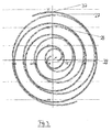
- the gas inlet 15 opens into a suction region 37 (cf. Fig. 3 ) formed by the first and second scrolls 25, 27 in a radially outer region.
- the first spiral 25 moves on a circular path due to an eccentric drive 36 and performs a so-called center-symmetric oscillation, which is also called “wobbling” or “orbiting". Between the spirals 25, 27 arise so completed crescent-shaped volumes or cavities, the to reduce their volume further and further inside.
- the gas is thus conveyed radially inwards via the suction region 37 via the cavities formed between the spirals 25, 27 and expelled through an ejection region 39 into the gas outlet 17 in the middle of the spiral.
- the eccentric drive 36 is used to drive the first scroll 25 and the movable part 21 of the scroll pump stage 19, respectively.
- the eccentric drive 36 comprises an eccentric shaft 41 which is mounted by means of a bearing 43 and has at its axial end a section 45 whose longitudinal axis L is offset parallel to the axis of rotation R of the eccentric shaft 41.
- the movable part 21 comprises a bearing 47, which is attached to the shaft portion 45, such as Fig. 1 shows.
- balancing weights 49 are arranged on the eccentric shaft 41.
- a metallic bellows 51 between the inside of the housing 13 and the back 67 of the first wall 29 is arranged for hermetic sealing and rotation prevention.
- a synchronous motor 53 is provided in the housing 13, which has a stator 55 and a rotor 57.
- the rotor 57 is coupled to the shaft 41 and thus to the movable part 21 of the scroll pump 19.
- the synchronous motor 53 is preferably a permanent magnet-excited synchronous motor, in which the rotor 57 has a plurality of permanent magnets 59, preferably embedded in the rotor 57, such as Fig. 5 shows.
- the permanent magnets 59 can be inserted, for example, in slots provided in the rotor 57.
- the slots may be hermetically sealed to protect the permanent magnets, for example from corrosive gas.
- the scroll pump 11 may further include a controller 61 coupled to the synchronous motor 53 and configured to control and / or regulate the rotational speed of the rotor 57.
- the controller 61 may have a, in particular sensorless, position detection of the rotor and advantageously also has a wide voltage input, for example, for supply voltages of 90 to 230 volts or, for example for supply voltages of 24 to 48 volts on.
- the controller 61 can change the rotational speed of the rotor 57 and thus the rotational speed of the first spiral 25 almost arbitrarily.
- the abrasion of the seals 33, 35 during pump operation depends on the sliding speed of the seals 33, 35 on the walls 29, 31 and thus on the speed of the rotor 57.
- Other parameters that have an influence on the abrasion of the seals 33, 35 are the contact pressure of the seals 33, 35 on the walls 29, 31 and the temperature.
- the temperature can be at least indirectly influenced by the speed of the rotor 57, since at higher speed of the rotor 57 and higher temperatures occur in the pump. By adjusting the rotational speed of the rotor 57 during pump operation, the wear of the seals 33, 35 can be reduced and the temperature in the pump 11 can be influenced.
- the speed of movement of the first spiral 25 and thus the speed of the rotor 57 also have a decisive influence on the pumping capacity or the pump capacity and the achievable final pressure or the compression ratio of the pump 11.
- the scroll pump may have at least one temperature sensor 63 in the region of the pumping system, for example on the rear wall 67 of the first wall 29, and a pressure sensor 65, for example in the region of the gas inlet 15.
- the controller 61 may therefore be designed to control the rotational speed of the rotor 57 as a function of a pressure and / or a temperature of the scroll pump 11 to control and / or to regulate. This makes it possible, for example, when the temperature of the scroll pump exceeds a certain, predetermined or predefinable threshold, to lower the speed of the rotor 57 in order to achieve no further increase or possibly even a reduction in the temperature of the scroll pump.
- the controller 61 may also be configured to adjust the rotational speed of the rotor 57 in accordance with a, for example, a user of the pump 11 predetermined or predetermined operating parameters of the pump 11, such as a desired suction pressure or a desired pumping speed such that the Operating parameters is achieved.
- a related operating parameter such as, for example, the intake pressure or the pumping speed, can be achieved.
- the controller 61 may allow a user to input an operating parameter and then adjust the speed of the rotor 57 so that the operating parameter is actually achieved.
- the controller may also be designed to control and / or regulate the rotational speed of the rotor 57 as a function of the pressure measured via the pressure sensor 65 in such a way that the pumping speed of the pump 11 changes in accordance with a predefined or specifiable profile.
- the pumping speed of the pump 11 can be adjusted so that it follows the predetermined course and thus, for example, only slight fluctuations occur. In particular, slumps in the pumping speed, which can occur at certain pressures in scroll pumps known from the prior art, can be avoided in this way.
- Slumps in absorbency, especially through worn tip seals, can also be avoided by leveling or adjusting tip seals.
- the controller 61 may be configured to reduce the speed of the rotor 57 upon reaching a certain pressure, for example a final pressure of the pump 11.
- a pressure-dependent speed control of the scroll pump can also take place.
- the user of the pump can preselect, for example, a suction pressure and the controller 61, depending on the upcoming gas load or the pressure measured by the pressure sensor 65, the speed of the rotor 57, as far as it is within the approved control range set.
- the controller 61 may be designed to switch off the electric motor 53 at least for a short time when a specific pressure, in particular a final pressure of the pump 11, is reached or to operate at a predetermined or predefinable, in particular minimum, speed. After reaching the final pressure, it is only necessary to keep this final pressure. In this case, a lower suction power is required than during the actual pumping out of the recipient is required. Therefore, it is possible to temporarily shut off the synchronous motor 53 to achieve a corresponding energy saving.
- the duration of the shutdown can be selected so as to ensure that during shutdown no or only a slight increase in the pressure in the recipient takes place.
- the pump can after reaching the final pressure at a be operated predetermined minimum speed, on the one hand to keep the final pressure, but on the other hand to achieve energy savings.
- the controller 61 may be configured to switch it on again after a shutdown of the motor 53, for example as a function of the pressure measured by the pressure sensor 65.
- a maximum permissible rotational speed value for the rotor 57 can be predetermined for the normal operation of the pump.
- the controller 61 may be configured to monitor the speed of the rotor 57 and to ensure that the maximum allowable speed value is not exceeded during normal operation of the pump 11.
- the controller 11 may also be configured to increase the speed of the rotor 57 over the maximum allowable speed value. The pump 11 can thus be operated in a boost mode to realize a short time high pumping speed.
- the Fig. 1 has the scroll pump 11 'of Fig. 4 a synchronous electric motor 53, in which the rotor 57 is arranged relative to the stator 55, that during the operation of the electric motor 53 in the axial direction, ie along the axis of rotation R, directed force F is generated on the rotor 57.
- the first wall 29 is pressed in the direction of the second wall 31, whereby the seals 33, 35 between the movable and fixed parts 21, 23 of the scroll pump 11 are compressed.
- the sealing effect of the seals 33, 35 is thereby improved.
- the seals 33, 35 By acting in the axial direction of force F not only the seals 33, 35 can be compressed or biased to increase the sealing effect, but it can also be the bearings 43, 47 are relieved. As a result, smaller and cheaper bearings can be used. Furthermore, the axial force F can be used to compensate for the compression forces in the pumping stage 19 in the axial direction and / or axial compressive forces in the pumping system.
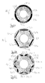
- an electric motor 53 with an axial offset V between the stator 55 and the rotor 57 is suitable for use in connection with a single-wrap pumping stage (cf. Fig. 2B ) as well as in connection with a double-wrap pump stage (cf. Fig. 2A ).
- pumping stages 19 are so-called single-wrap pumping stages.
- Fig. 2B shows, the movable and the fixed scroll 25, 27 are arranged between the first and the second wall 29, 31, while on the back 67 of the second wall 29, no movable coil is provided.
- first wall 29 also a movable spiral cylinder 69 is provided, which is inserted into one another with an immovable spiral cylinder 71, one end face with a third wall 73 gas-tight connected or formed integrally therewith.
- a seal 75 is provided, and between a front face of the fixed scroll 71 and the first wall 29, in turn, a seal 77 is provided.
- An advantage of a double-wrap arrangement is that a pressure compensation in the axial direction is achieved and thus lower axial forces act on the seals. The power consumption of the electric motor 53 can thereby be reduced.
- the rotor 57 may have six rotor poles 79 in the circumferential direction U, each rotor pole 79 having one of the permanent magnets 59a-59f.
- the magnetization direction which is directed from the south pole to the north pole, can be seen in the permanent magnet 59a-59f in the circumferential direction U alternately directed radially inward or radially outward. Therefore, in the permanent magnets 59a, 59c, and 59e, the magnetization direction may be directed radially outward while being directed radially inward of the permanent magnets 59b, 59d, and 59f.
- the permanent magnets 59a - 59f attached to the radially outer side, for example glued, and thus not embedded.
- the magnetization direction can be directed radially outward, while it is directed radially inward in the case of the permanent magnets 59b, 59d and 59f.
- each rotor pole on two permanent magnets which are each arranged in a V-like and embedded in the rotor 57.
- One rotor pole comprises the permanent magnets 59a-1, 59a-2
- another rotor pole comprises the permanent magnets 59b-1, 59b-2
- another rotor pole comprises the permanent magnets 59c-1, 59c-2
- another rotor pole comprises the permanent magnets 59d-1 59d-2
- another rotor pole includes the permanent magnets 59e-1, 59e-2
- still another rotor pole includes the permanent magnets 59f-1, 59f-2.
- the direction of magnetization of the permanent magnets can in turn be directed in the circumferential direction from rotor pole to rotor pole radially outward or radially inward.
- the longitudinal direction of the permanent magnets 59a-59f extends in the radial direction.
- the magnetization can be directed radially outward in all permanent magnets 59a-59f.
- Each pole has four permanent magnets arranged in two rows in a V-shape.
- the permanent magnets 59a-1, 59a-2, 59a-3, 59a-4 are marked with reference numerals.
- the direction of magnetization of the permanent magnets can in turn be directed in the circumferential direction from rotor pole to rotor pole radially outward or radially inward.
- Each of the illustrated rotors 57 may be used in a synchronous motor 53 of the pump 11 or the pump 11 '.
Landscapes
- Engineering & Computer Science (AREA)
- Mechanical Engineering (AREA)
- General Engineering & Computer Science (AREA)
- Applications Or Details Of Rotary Compressors (AREA)
- Rotary Pumps (AREA)
- Compressor (AREA)
Abstract
Description
- Die vorliegende Erfindung betrifft eine Scrollpumpe, insbesondere Scrollvakuumpumpe, mit wenigstens einer Scrollpumpstufe zum Fördern eines Gases von einem Gaseinlass durch die Scrollpumpstufe hindurch zu einem Gasauslass, und einem Elektromotor, der einen Stator und einen Läufer aufweist, wobei der Läufer zum Antreiben eines orbitierenden Teils der Scrollpumpstufe mit dem orbitierenden Teil der Scrollpumpstufe gekoppelt ist. Die vorliegende Erfindung betrifft außerdem ein Verfahren zum Betreiben einer derartigen Scrollpumpe.
- Eine Scrollpumpe ist eine gegen Atmosphärendruck verdichtende Verdrängerpumpe, die sich unter anderem als Kompressor einsetzen lässt. Eine Scrollvakuumpumpe kann zur Erzeugung eines Vakuums in einem an den Gaseinlass angeschlossenen Rezipienten verwendet werden. Scrollvakuumpumpen werden beispielsweise in der
EP 0 798 463 A2 und derDE 199 14 770 A1 beschrieben. - Scrollvakuumpumpen werden auch als Spiralvakuumpumpen oder Spiralfluidfördereinrichtungen bezeichnet. Das einer Scrollpumpe zugrunde liegende Pumpprinzip ist aus dem Stand der Technik bekannt und wird nachstehend erläutert. Eine Pumpstufe einer Scrollpumpe weist zwei ineinander gesteckte, beispielsweise archimedische Spiralzylinder auf, welche nachstehend auch als Spiralen bezeichnet werden. Jeder Spiralzylinder besteht dabei aus einer äquidistanten Spiralwand mit einer an einer Stirnseite der Spiralwand vorgesehenen Grundplatte. Die Spiralzylinder sind so ineinander gesteckt, dass die Spiralzylinder abschnittsweise halbmondförmige Volumina umschließen. Dabei steht eine Spirale fest, während die andere Spirale über einen Exzenterantrieb auf einer kreisförmigen Bahn bewegt werden kann. Die bewegbare Spirale führt somit eine sogenannte zentralsymmetrische Oszillation aus, was auch als "wobbeln" bezeichnet wird. Ein zwischen den Spiralzylindern eingeschlossenes halbmondförmiges Volumen wandert während des Wobbelns der beweglichen Spirale innerhalb der Spiralwände weiter, wodurch mittels des wandernden Volumens Gas von einem radial außen liegenden Gaseinlass nach radial innen zu einem in der Spiralenmitte liegenden Gasauslass gefördert wird.
- Nach dem Stand der Technik wird zum Antreiben des die bewegliche Spirale aufweisenden beweglichen Teils der Scrollpumpstufe ein als Asynchron-Antrieb ausgestalteter Elektromotor eingesetzt. Nachteilig daran ist insbesondere, dass Asynchron-Elektromotoren einen verhältnismäßig schlechten Wirkungsgrad aufweisen und zur Entstehung von relativ hohen Temperaturen in der Scrollpumpe beitragen können.
- Der vorliegenden Erfindung liegt daher die Aufgabe zugrunde, eine Scrollpumpe mit einem verbesserten elektrischen Antrieb bereitzustellen.
- Die Aufgabe wird durch eine Scrollpumpe mit den Merkmalen des Anspruch 1 und insbesondere dadurch gelöst, dass eine Scrollpumpe der eingangs genannten Art dadurch weitergebildet wird, dass als Elektromotor ein Synchronmotor eingesetzt wird.
- Synchronmotoren haben im Vergleich zu Asynchronmotoren einen besseren Wirkungsgrad. Daher erwärmt sich ein Synchronmotor bei gleicher Ausgangsleistung weniger stark als ein Asynchronmotor. Bei gleicher Ausgangsleistung bewirkt somit ein Synchronmotor eine weniger starke Erwärmung der Scrollpumpe. Dies hat unter anderem den Vorteil, dass die Lebensdauer von Dichtungsmaterialien, die in der Pumpe verwendet werden und die normalerweise aus einem Kunststoff ausgebildet sind, verlängert werden kann. Insbesondere kann - aufgrund der geringeren Erwärmung der Scrollpumpe bei Verwendung eines Synchronmotors - die Lebensdauer von sogenannten Tip Seals, wie nachstehend noch näher erläutert wird, verlängert werden.
- Weiterhin ist an der Verwendung eines Synchronmotors vorteilhaft, dass die Drehzahl des Läufers über einen großen Drehzahlbereich variiert werden kann. Die Saugleistung einer Scrollpumpe wird im Wesentlichen durch die Höhe der Spiralwände, deren Abstand, durch den Außendurchmesser und durch die Bewegungsgeschwindigkeit der beweglichen Spirale relativ zur feststehenden Spirale bestimmt. Die Bewegungsgeschwindigkeit der beweglichen Spirale ist normalerweise abhängig von der Drehzahl des Läufers des Elektromotors oder ist - wenn zwischen dem Läufer und der beweglichen Spirale ein Getriebe geschaltet ist - zumindest mit der Drehzahl des Läufers korreliert. Durch Variieren der Drehzahl des Läufers kann somit die Saugleistung der Scrollpumpe verändert werden. Beispielsweise kann zu Beginn des Pumpenbetriebs, um einen an den Gaseinlass angeschlossenen Rezipienten auszupumpen, die Drehzahl des Läufers und damit die Saugleistung der Scrollpumpe auf einen hohen Wert eingestellt werden. Nach Erreichen eines Enddrucks kann dann die Drehzahl und entsprechend die Saugleistung verringert werden, da der Enddruck auch mit geringerer Saugleistung gehalten werden kann. Durch Verringern der Drehzahl des Läufers lässt sich die Leistungsaufnahme des Elektromotors verringern, wodurch eine Energieeinsparung realisiert werden kann. Wenn man berücksichtigt, dass der Abpumpvorgang zur Evakuierung eines Rezipienten nur einen geringen Bruchteil an Zeit im Vergleich zu dem restlichen Pumpenbetrieb beansprucht, während dessen der erreichte Enddruck im Rezipienten nur noch gehalten werden muss, kann durch die Reduzierung der Drehzahl des Läufers des Elektromotors eine beträchtliche Energieeinsparung realisiert werden.
- Nach einer bevorzugten Weiterbildung der Erfindung ist der Synchronmotor ein permanentmagneterregter Synchronmotor. Bei dem Synchronmotor kann es sich somit um einen PM-Synchronmotor handeln, wobei PM für Permanentmagnet steht.
- Besonders bevorzugt ist der permanentmagneterregte Synchronmotor derart ausgebildet, dass jeder Pol des Läufers wenigstens einen in den Läufer eingebetteten Permanentmagnet aufweist. Durch die Einbettung der Permanentmagnete in den Läufer kann ein separater Halter für die Permanentmagnete eingespart werden. Außerdem können die Permanentmagnete durch den sie umgebenden Läufer vor Prozessgasen geschützt werden. Die Permanentmagnete können auch an der Oberfläche des Läufers angeordnet, z.B. festgeklebt, sein.
- Bevorzugt ist eine Steuerung zum Steuern und/oder Regeln der Drehzahl des Läufers vorgesehen. Bevorzugt ist die Steuerung in die Pumpe integriert.
- Die Steuerung kann dazu ausgebildet sein, die Drehzahl des Läufers in Abhängigkeit von einem Druck und/oder einer Temperatur der Scrollpumpe zu steuern und/oder zu regeln. Zur Messung des Drucks kann die Pumpe wenigstens einen Drucksensor aufweisen. Mittels des Drucksensors kann beispielsweise der im Gaseinlass herrschende Druck erfasst werden. Zur Erfassung einer Temperatur der Pumpe kann wenigstens ein Temperatursensor vorgesehen sein. Mit dem Temperatursensor kann beispielsweise die Temperatur der beweglichen Spirale oder der feststehenden Spirale oder die Temperatur einer Dichtung, insbesondere eines Tip Seal, gemessen werden.
- Vorteilhaft an einer Steuerung, die die Drehzahl des Läufers in Abhängigkeit von einem Druck und/oder einer Temperatur der Scrollpumpe steuert oder regelt, ist insbesondere, dass diese die Drehzahl des Läufers reduzieren kann, nachdem der Enddruck erreicht ist. Dadurch kann, wie vorstehend bereits erläutert wurde, eine Energieersparnis erzielt werden. Außerdem kann die Drehzahl des Läufers abgesenkt werden, wenn die Temperatur der Scrollpumpe einen bestimmten, vorgegebenen oder vorgebbaren Schwellenwert überschreitet. Da sich bei einer Scrollpumpe die bewegliche Spirale relativ zur feststehenden Spirale bewegt, ergibt sich zwischen den Spiralen eine Reibung, die in Verbindung mit der bewirkten Kompression des Gases eine erhebliche Erwärmung in der Scrollpumpe bewirkt. Durch Reduzierung der Drehzahl des Läufers kann auch die Relativbewegung der Spiralen zueinander verlangsamt werden, sodass eine geringere Abwärme erzeugt wird. Durch Verändern bzw. Verringern der Drehzahl des Läufers kann somit eine weitere Zunahme der Temperatur der Scrollpumpe vermieden bzw. die Temperatur der Scrollpumpe kann eventuell sogar abgesenkt werden. Bei entsprechender Wahl der Schwellenwerttemperatur kann insbesondere eine Zerstörung bzw. ein starker Verschleiß an den Dichtungen der Scrollpumpe vermieden werden.
- Nach einer bevorzugten Weiterbildung der Erfindung ist die Steuerung dazu ausgebildet, in Abhängigkeit von einem, vorzugsweise von einem Benutzer der Pumpe vorgegebenen, Betriebsparameter der Pumpe, wie etwa einem gewünschten Ansaugdruck oder einem gewünschten Saugvermögen, die Drehzahl des Läufers derart einzustellen, dass der Betriebsparameter zumindest annähernd erreicht wird. Durch die Einstellbarkeit der Drehzahl des Läufers kann somit ein damit zusammenhängender Betriebsparameter, wie etwa der Ansaugdruck oder das Saugvermögen, so eingestellt werden, dass der Betriebsparameter auch tatsächlich von der Pumpe realisiert werden kann.
- Die Steuerung kann es beispielsweise ermöglichen, dass ein Benutzer der Pumpe den Betriebsparameter festlegt. Daraufhin kann die Steuerung die Drehzahl des Läufers so einstellen, dass der Betriebsparameter tatsächlich erreicht wird. Die Steuerung kann auch eine Regelung sein. Zur Erreichung des Betriebsparameters kann bspw. ein Abgleich des Ist-Werts des Betriebsparameters mit einem SollWert erfolgen.
- Die Steuerung kann dazu ausgebildet sein, die Drehzahl des Läufers in Abhängigkeit von einem Druck derart zu steuern und/oder zu regeln, dass sich das Saugvermögen der Pumpe entsprechend einem vorgegebenen oder vorgebbaren Verlauf ändert. Während des Auspumpens eines Rezipienten kann die Drehzahl des Läufers beispielsweise so eingestellt werden, dass sich über den Auspumpvorgang gesehen das Saugvermögen der Pumpe linear ändert oder nur geringfügigen Schwankungen unterliegt. Einbrüche des Saugvermögens, die bei bestimmten Drücken im Gaseinlass auftreten können, lassen sich dadurch vermeiden.
- Nach einer bevorzugten Weiterbildung der Erfindung ist die Steuerung dazu ausgebildet, bei Erreichen eines bestimmten Drucks, insbesondere eines Enddrucks, die Drehzahl des Läufers zu reduzieren, insbesondere um einen vorgegebenen oder vorgebbaren, bestimmten Betrag. Wie vorstehend bereits ausgeführt wurde, kann durch die Reduzierung der Drehzahl des Läufers eine möglicherweise erhebliche Energieeinsparung erreicht werden.
- Bevorzugt ist die Steuerung dazu ausgebildet, bei Erreichen eines bestimmten Drucks, insbesondere eines Enddrucks, den Elektromotor kurzzeitig abzuschalten oder bei einer vorgegebenen oder vorgebbaren, insbesondere minimalen, Drehzahl des Läufers zu betreiben. Nach Erreichen des Enddrucks ist es nur noch erforderlich, diesen Enddruck wenigstens annähernd zu halten. Die Pumpe kann daher nach dem Erreichen des Enddrucks bei einer geringeren Saugleistung betrieben werden als zur Erzeugung des Enddrucks erforderlich ist. Auch ist es möglich, den Elektromotor kurzzeitig abzuschalten, um eine entsprechende Energieersparnis zu erreichen. Die Zeitdauer der Abschaltung kann dabei so gewählt sein, dass - zum Beispiel anhand empirisch gewonnener Daten - sichergestellt ist, dass während der Abschaltung kein oder nur ein geringfügiger Anstieg des Drucks im Rezipienten stattfindet. Durch den Betrieb der Pumpe mit einem bei minimaler Drehzahl laufendem Läufer kann ebenfalls eine erhebliche Energieersparnis erreicht und sichergestellt werden, dass der Druck im Rezipienten nicht oder allenfalls nur geringfügig ansteigt.
- Wenn vorgesehen ist, dass die Steuerung den Elektromotor kurzzeitig abschaltet, ist es vorteilhaft, wenn die Steuerung dazu ausgebildet ist, den Elektromotor nach dem Abschalten wieder zu betreiben, zum Beispiel, wenn nach dem Abschalten des Elektromotors ein Druckanstieg gemessen wird.
- Nach einer bevorzugten Weiterbildung der Erfindung ist für den Normalbetrieb der Pumpe ein maximal zulässiger Drehzahlbereich für den Läufer vorgegeben, und die Steuerung ist dazu ausgebildet, die Drehzahl des Läufers über den maximal zulässigen Drehzahlwert zu steigern. Die Pumpe kann somit in einer Art Boost-Funktion betrieben werden, bei der ein festgelegter, normalerweise maximal zulässiger Drehzahlwert wenigstens kurzzeitig überschritten werden kann, insbesondere um kurzzeitig ein hohes Saugvermögen am Gaseinlass der Pumpe zu realisieren. Durch die Boost-Funktion können auch eventuelle Einbrüche des Saugvermögens ausgeglichen werden.
- Insbesondere kann die Steuerung dazu ausgebildet sein, die Drehzahl des Läufers über den maximal zulässigen Drehzahlwert zu steigern, wenn ein bestimmter, vorgegebener Druckwert und/oder eine bestimmte, vorgegebene Temperatur in der Pumpe, insbesondere an einer in der Pumpe vorgesehenen Dichtung, erreicht wird.
- Nach einer bevorzugten Weiterbildung, die auch als unabhängige Erfindung beansprucht wird, ist der Läufer des Elektromotors derart relativ zum Stator des Elektromotors angeordnet, dass während des Betriebs des Elektromotors eine, in eine axiale Richtung gerichtete, axiale Kraft auf den Läufer erzeugt wird. Die axiale Richtung bezieht sich dabei auf eine Richtung längs der Drehachse des Läufers. Zur Erzeugung der axialen Kraft kann der Läufer, bezogen auf seine Normallage zum Stator, längs der axialen Richtung versetzt zum Stator angeordnet sein. Vorzugsweise ist der Läufer bezogen auf seine Normallage zum Stator entgegen der axialen Richtung um einen Versatz versetzt angeordnet. Dabei ist mit Normallage diejenige Lage gemeint, in der die senkrecht zur Rotationsachse verlaufenden Mittelebenen von Läufer und Stator übereinander liegen.
- Der Läufer kann derart mit dem beweglichen Teil der Scrollpumpe gekoppelt sein, dass die axiale Kraft auf den beweglichen Teil der Scrollpumpstufe übertragen wird. Der bewegliche Teil der Scrollpumpstufe kann somit während des Betriebs des Elektromotors in axialer Richtung mit der axialen Kraft beaufschlagt werden.
- In axialer Richtung gesehen kann zwischen dem beweglichen Teil der Scrollpumpstufe und einem unbeweglichen Teil der Scrollpumpstufe wenigstens eine Dichtung angeordnet sein, die durch die axiale Kraft zwischen dem beweglichen und dem unbeweglichen Teil der Scrollpumpstufe zusammengedrückt oder angepresst wird. Mittels der axialen Kraft lässt sich der bewegliche Teil der Scrollpumpstufe in Richtung des unbeweglichen Teils der Scrollpumpstufe vorspannen und eine dazwischenliegende Dichtung, insbesondere ein sogenanntes Tip Seal, kann dadurch zusammengedrückt werden. Dadurch kann die Wirkung der Dichtung verbessert werden.
- Die Erfindung betrifft auch ein Verfahren zum Betreiben einer Scrollpumpe, insbesondere Scrollvakuumpumpe, mit wenigstens einer Scrollpumpstufe zum Fördern eines Gases von einem Gaseinlass durch die Scrollpumpe hindurch zu einem Gasauslass und einem Elektromotor, der einen Stator und einen Läufer aufweist, wobei der Läufer zum Antreiben eines beweglichen Teils der Scrollpumpstufe mit dem beweglichen Teil der Scrollpumpstufe gekoppelt ist, und wobei bei dem Verfahren die Drehzahl des Läufers in Abhängigkeit von einem Druck und/oder einer Temperatur der Scrollpumpe gesteuert und/oder geregelt wird.
- Die Erfindung wird nachfolgend beispielhaft mit Bezugnahme auf die beiliegenden Zeichnungen erläutert. Es zeigen, jeweils schematisch,
- Fig. 1
- einen Längsschnitt durch eine erfindungsgemäße Scrollvakuumpumpe,
- Fig. 2A
- einen Längsschnitt durch eine Pumpstufe einer Scrollvakuumpumpe,
- Fig. 2B
- einen Längsschnitt durch eine Pumpstufe einer weiteren Scrollvakuumpumpe,
- Fig. 3
- einen Querschnitt der Pumpstufe der Scrollvakuumpumpe von
Fig. 1 , - Fig. 4
- einen Längsschnitt durch eine weitere erfindungsgemäße Scrollvakuumpumpe,
- Fig. 5
- einen Querschnitt durch einen Stator und Rotor eines Synchron-Elektromotors, und
- Fig. 6A - 6E
- verschiedene Abwandlungen von Rotoren für einen Synchron-Elektromotor.
- Die in
Fig. 1 gezeigte Scrollvakuumpumpe 11 weist ein Gehäuse 13 auf, in welchem ein Gaseinlass 15 und ein Gasauslass 17 vorgesehen sind. An den Gaseinlass 15 kann ein Auslass eines nicht gezeigten Rezipienten angeschlossen werden. Eine im Gehäuse 13 vorgesehene Scrollpumpstufe 19 kann Gas aus dem Rezipienten durch den Gaseinlass 15 hindurch evakuieren und durch die Scrollpumpstufe 19 hindurch zu dem Gasauslass 17 fördern. Die Scrollpumpstufe 19 weist einen beweglichen Teil 21 und einen feststehenden Teil 23 auf. Der bewegliche Teil 21 umfasst einen ersten, beweglichen Spiralzylinder 25. Der feststehende Teil 23 weist einen zweiten, feststehenden Spiralzylinder 27 auf. Der erste Spiralzylinder 25 und der zweite Spiralzylinder 27 werden nachfolgend auch als erste Spirale 25 und zweite Spirale 27 bezeichnet. Die erste Spirale 25 und die zweite Spirale 27 sind - wie bei Scrollpumpen an sich bekannt ist - ineinandergesteckt. Der erste Spiralzylinder 25 weist an jedem axialen Ende eine jeweilige Stirnfläche auf. Eine der Stirnflächen des ersten Spiralzylinders 25 ist mit einer ersten Wand 29 gasdicht verbunden oder einstückig mit dieser ausgebildet. Die erste Wand 29 bildet gewissermaßen eine Grundplatte, auf der die Spirale 25 angeordnet ist. In entsprechender Weise ist eine der Stirnflächen des zweiten Spiralzylinders 27 mit einer zweiten Wand 31 gasdicht verbunden oder einstückig mit dieser ausgebildet. - An der Stirnfläche des beweglichen ersten Spiralzylinders 25, die der feststehenden, zweiten Wand 31 gegenübersteht, ist eine erste Dichtung 33 angeordnet, die auch als Tip Seal bezeichnet wird. Bei einem Tip Seal handelt es sich beispielsweise um einen Kunststoff-Compound (PTFE) mit rechteckigem Querschnitt.
- Zwischen der Stirnfläche des feststehenden zweiten Spiralzylinders 27, die der beweglichen, ersten Wand 29 zugewandt ist, ist ebenfalls eine zweite Dichtung 35 vorgesehen, die ebenfalls als Tip Seal bezeichnet wird. Durch die Dichtungen 33, 35 lassen sich die von den Spiralzylindern 25, 27 eingeschlossenen, halbmondförmigen Volumina an den Stirnflächen der Spiralzylinder 25, 27 abdichten.
- Der Gaseinlass 15 mündet in einen Ansaugbereich 37 (vgl.
Fig. 3 ), den die erste und zweite Spirale 25, 27 in einem radial außenliegenden Bereich bilden. Die erste Spiral 25 bewegt sich aufgrund eines Exzenterantriebs 36 auf einer kreisförmigen Bahn und führt eine sogenannte zentralsymmetrische Oszillation aus, die auch als "wobbeln" oder als "orbiting" bezeichnet wird. Zwischen den Spiralen 25, 27 entstehen so abgeschlossene halbmondförmige Volumina bzw. Hohlräume, die ihr Volumen nach innen immer weiter verkleinern. Das Gas wird somit über den Ansaugbereich 37 über die zwischen den Spiralen 25, 27 entstehenden Hohlräume nach radial innen gefördert und in der Spiralenmitte durch einen Ausstoßbereich 39 in den Gasauslass 17 ausgestoßen. - Wie vorstehend erwähnt wurde, wird zum Antreiben der ersten Spirale 25 bzw. des beweglichen Teils 21 der Scrollpumpstufe 19 der Exzenterantrieb 36 verwendet. Der Exzenterantrieb 36 umfasst eine mittels Lager 43 gelagerte Exzenterwelle 41, die an ihrem axialen Ende einen Abschnitt 45 aufweist, dessen Längsachse L zur Rotationsachse R der Exzenterwelle 41 parallel versetzt ist. Der bewegliche Teil 21 umfasst ein Lager 47, das auf den Wellenabschnitt 45 aufgesteckt ist, wie
Fig. 1 zeigt. Zum Ausgleichen der exzentrischen Bewegung der beweglichen ersten Spirale 25 sind an der Exzenterwelle 41 Ausgleichsgewichte 49 angeordnet. Außerdem ist zur hermetischen Abdichtung und Drehverhinderung ein metallischer Wellbalg 51 zwischen der Innenseite des Gehäuses 13 und der Rückseite 67 der ersten Wand 29 angeordnet. - Zum Antreiben der Exzenterwelle 41 ist im Gehäuse 13 ein Synchronmotor 53 vorgesehen, welcher einen Stator 55 und einen Läufer 57 aufweist. Der Läufer 57 ist dabei mit der Welle 41 und somit mit dem beweglichen Teil 21 der Scrollpumpe 19 gekoppelt.
- Bei dem Synchronmotor 53 handelt es sich vorzugsweise um einen permanentmagneterregten Synchronmotor, bei dem der Läufer 57 mehrere, vorzugsweise in den Läufer 57 eingebettete Permanentmagnete 59 aufweist, wie
Fig. 5 zeigt. Die Permanentmagnete 59 können beispielsweise in im Läufer 57 vorgesehenen Schlitzen eingeschoben sein. Die Schlitze können hermetisch abgedichtet sein, um die Permanentmagnete, zum Beispiel vor korrosiv wirkendem Gas, zu schützen. - Die Scrollpumpe 11 kann ferner eine Steuerung 61 aufweisen, die mit dem Synchronmotor 53 gekoppelt und zum Steuern und/oder Regeln der Drehzahl des Läufers 57 ausgebildet ist. Die Steuerung 61 kann über eine, insbesondere sensorlose, Positionserkennung des Läufers verfügen und weist vorteilhafterweise auch einen Weitspannungseingang, zum Beispiel für Versorgungsspannungen von 90 bis 230 Volt oder zum Beispiel für Versorgungsspannungen von 24 bis 48 Volt, auf.
- Die Steuerung 61 kann die Drehzahl des Läufers 57 und somit die Drehzahl der ersten Spirale 25 nahezu beliebig verändern. Der Abrieb der Dichtungen 33, 35 während des Pumpenbetriebs hängt von der Gleitgeschwindigkeit der Dichtungen 33, 35 an den Wänden 29, 31 und somit von der Drehzahl des Läufers 57 ab. Weitere Parameter, die einen Einfluss auf den Abrieb der Dichtungen 33, 35 haben, sind die Anpresskraft der Dichtungen 33, 35 an die Wände 29, 31 und die Temperatur. Auch die Temperatur lässt sich wenigstens indirekt über die Drehzahl des Läufers 57 beeinflussen, da bei höherer Drehzahl des Läufers 57 auch höhere Temperaturen in der Pumpe auftreten. Durch Anpassung der Drehzahl des Läufers 57 während des Pumpenbetriebs kann der Abrieb der Dichtungen 33, 35 vermindert und die Temperatur in der Pumpe 11 kann beeinflusst werden.
- Die Bewegungsgeschwindigkeit der ersten Spirale 25 und somit die Drehzahl des Läufers 57 haben außerdem einen entscheidenden Einfluss auf das Saugvermögen bzw. auf die Pumpenkapazität und den erreichbaren Enddruck bzw. das Kompressionsverhältnis der Pumpe 11.
- Die Scrollpumpe kann wenigstens einen Temperatursensor 63 im Bereich des Pumpsystems, beispielsweise an der Rückwand 67 der ersten Wand 29, und einen Drucksensor 65, zum Beispiel im Bereich des Gaseinlasses 15, aufweisen. Die Steuerung 61 kann daher dazu ausgebildet sein, die Drehzahl des Läufers 57 in Abhängigkeit von einem Druck und/oder einer Temperatur der Scrollpumpe 11 zu steuern und/oder zu regeln. Dadurch wird es beispielsweise möglich, wenn die Temperatur der Scrollpumpe einen bestimmten, vorgegebenen oder vorgebbaren Schwellenwert überschreitet, die Drehzahl des Läufers 57 abzusenken, um keinen weiteren Anstieg oder eventuell sogar eine Senkung der Temperatur der Scrollpumpe zu erreichen.
- Die Steuerung 61 kann auch dazu ausgebildet sein, in Abhängigkeit von einem, zum Beispiel für einen Benutzer der Pumpe 11 vorgegebenen oder vorgebbaren Betriebsparameter der Pumpe 11, wie etwa einem gewünschten Ansaugdruck oder einem gewünschten Saugvermögen, die Drehzahl des Läufers 57 derart einzustellen, dass der Betriebsparameter erreicht wird. Durch die Einstellbarkeit der Drehzahl des Läufers 57 kann somit ein damit zusammenhängender Betriebsparameter, wie etwa der Ansaugdruck oder das Saugvermögen, erreicht werden.
- Die Steuerung 61 kann einem Benutzer die Eingabe eines Betriebsparameters ermöglichen und daraufhin die Drehzahl des Läufers 57 derart einstellen, dass der Betriebsparameter tatsächlich erreicht wird. Die Steuerung kann auch dazu ausgebildet sein, die Drehzahl des Läufers 57 in Abhängigkeit von dem über den Drucksensor 65 gemessenen Druck derart zu steuern und/oder zu regeln, dass sich das Saugvermögen der Pumpe 11 entsprechend einem vorgegebenen oder vorgebbaren Verlauf ändert. Während des Auspumpvorgangs des Rezipienten kann beispielsweise über die Drehzahl des Läufers 57 das Saugvermögen der Pumpe 11 so eingestellt werden, dass es dem vorgegebenen Verlauf folgt und somit beispielsweise nur geringfügige Schwankungen auftreten. Dadurch können insbesondere Einbrüche des Saugvermögens, die bei bestimmten Drücken bei aus dem Stand der Technik bekannten Scrollpumpen auftreten können, vermieden werden.
- Einbrüche des Saugvermögens, insbesondere durch verschlissene Tip Seals, können außerdem durch Ausgleichen bzw. Nachstellen der Tip Seals vermieden werden.
- Durch eine druckabhängige Drehzahlsteuerung der Drehzahl des Läufers 57 kann beispielsweise ein nahezu linearer Saugvermögensbereich bzw. -verlauf erzielt werden.
- Die Steuerung 61 kann dazu ausgebildet sein, bei Erreichen eines bestimmten Drucks, beispielsweise eines Enddrucks der Pumpe 11, die Drehzahl des Läufers 57 zu reduzieren.
- Mittels der Steuerung 61 kann auch eine druckabhängige Drehzahlregelung der Scrollpumpe erfolgen. Der Benutzer der Pumpe kann beispielsweise einen Ansaugdruck vorwählen und die Steuerung 61 kann in Abhängigkeit der anstehenden Gaslast bzw. des mittels des Drucksensors 65 gemessenen Drucks die Drehzahl des Läufers 57, soweit diese im zugelassenen Regelbereich liegt, einstellen.
- Die Steuerung 61 kann dazu ausgebildet sein, bei Erreichen eines bestimmten Drucks, insbesondere eines Enddrucks der Pumpe 11, den Elektromotor 53 wenigstens kurzzeitig abzuschalten oder bei einer vorgegebenen oder vorgebbaren, insbesondere minimalen, Drehzahl zu betreiben. Nach Erreichen des Enddrucks ist es nur noch erforderlich, diesen Enddruck zu halten. Dabei wird eine geringere Saugleistung benötigt als während des eigentlichen Auspumpvorgangs des Rezipienten erforderlich ist. Daher ist es möglich, den Synchronmotor 53 kurzzeitig abzuschalten, um eine entsprechende Energieersparnis zu erreichen. Die Zeitdauer der Abschaltung kann so gewählt sein, dass sichergestellt ist, dass während der Abschaltung kein oder nur ein geringfügiger Anstieg des Drucks im Rezipienten stattfindet. Die Pumpe kann nach Erreichen des Enddrucks auch bei einer vorgegebenen minimalen Drehzahl betrieben werden, um einerseits den Enddruck zu halten, andererseits aber eine Energieersparnis zu erreichen.
- Die Steuerung 61 kann dazu ausgebildet sein, nach einer Abschaltung des Motors 53 diesen wieder anzuschalten, zum Beispiel in Abhängigkeit des mit dem Drucksensor 65 gemessenen Drucks.
- Bei der Vakuumpumpe 11 kann für den Normalbetrieb der Pumpe ein maximal zulässiger Drehzahlwert für den Läufer 57 vorgegeben sein. Die Steuerung 61 kann so ausgestaltet sein, dass sie die Drehzahl des Läufers 57 überwacht und dafür sorgt, dass im Normalbetrieb der Pumpe 11 der maximal zulässige Drehzahlwert nicht überschritten wird. Allerdings kann die Steuerung 11 auch dazu ausgebildet sein, die Drehzahl des Läufers 57 über den maximal zulässigen Drehzahlwert zu steigern. Die Pumpe 11 kann somit in einem Boost-Betrieb betrieben werden, um kurzzeitig ein hohes Saugvermögen zu realisieren.
- Im Unterschied zu der Scrollpumpe der
Fig. 1 weist die Scrollpumpe 11' derFig. 4 einen Synchron-Elektromotor 53 auf, bei welchem der Läufer 57 derart relativ zum Stator 55 angeordnet ist, dass während des Betriebs des Elektromotors 53 eine in axialer Richtung, also längs der Rotationsachse R, gerichtete Kraft F auf den Läufer 57 erzeugt wird. Durch die axiale Kraft F wird die erste Wand 29 in Richtung der zweiten Wand 31 gedrückt, wodurch die Dichtungen 33, 35 zwischen den beweglichen und feststehenden Teilen 21, 23 der Scrollpumpe 11 zusammengedrückt werden. Die Dichtwirkung der Dichtungen 33, 35 wird dadurch verbessert. - Zur Erzeugung der axialen Kraft ist der Läufer 57, wie ein Vergleich zwischen den
Fig. 1 und 4 zeigt, bezogen auf seine inFig. 1 dargestellte Normallage zum Stator 55 entgegen der axialen Richtung um einen Versatz V versetzt zum Stator 55 angeordnet. Zwischen einer senkrecht zur Rotationsachse R verlaufenden Mittelebene M1 des Stators 55 und einer ebenfalls senkrecht zur Rotationsachse R verlaufenden Mittelebene M2 des Läufers 57 ist somit der erwähnte axiale Versatz V vorgesehen, aufgrund dessen während des Betriebs des Elektromotors 53 sich die in axialer Richtung wirkende Kraft F einstellt. Durch die in axialer Richtung wirkende Kraft F können nicht nur die Dichtungen 33, 35 zur Erhöhung der Dichtwirkung zusammengedrückt bzw. vorgespannt werden, sondern es können auch die Lager 43, 47 entlastet werden. Dadurch können kleinere und kostengünstigere Lager verwendet werden. Des Weiteren kann die axiale Kraft F dazu genutzt werden, um die Verdichtungskräfte bei der Pumpstufe 19 in axialer Richtung und/oder um axiale Druckkräfte im Pumpsystem auszugleichen. - Die Verwendung eines Elektromotors 53 mit einem axialen Versatz V zwischen dem Stator 55 und dem Läufer 57 eignet sich zur Verwendung im Zusammenhang mit einer Single-Wrap Pumpstufe (vgl.
Fig. 2B ) als auch im Zusammenhang mit einer Double-Wrap Pumpstufe (vgl.Fig. 2A ). Bei den in denFig. 1 und 4 gezeigten Pumpstufen 19 handelt es sich um sogenannte Single-Wrap Pumpstufen. WieFig. 2B zeigt, sind die bewegliche und die feststehende Spirale 25, 27 zwischen der ersten und der zweiten Wand 29, 31 angeordnet, während auf der Rückseite 67 der zweiten Wand 29 keine bewegliche Spirale vorgesehen ist. Demgegenüber ist bei der Double-Wrap Pumpstufe gemäßFig. 2A auf der Rückseite 67 der beweglichen, ersten Wand 29 ebenfalls ein beweglicher Spiralzylinder 69 vorgesehen, welcher mit einem unbeweglichen Spiralzylinder 71 ineinander gesteckt ist, dessen eine Stirnfläche mit einer dritten Wand 73 gasdicht verbunden oder einstückig mit dieser ausgebildet ist. Zwischen einer Stirnfläche der beweglichen Spirale 69 und der dritten Wand 73 ist wiederum eine Dichtung 75 vorgesehen, und zwischen einer Stirnfläche der unbeweglichen Spirale 71 und der ersten Wand 29 ist wiederum eine Dichtung 77 vorgesehen. Bei der Double-Wrap Anordnung befinden sich somit auf beiden Seiten der ersten Wand 29 ineinander gestellte Spiralzylinder. Vorteilhaft an einer Double-Wrap Anordnung ist, dass ein Druckausgleich in axialer Richtung erzielt wird und somit geringere Axialkräfte auf die Dichtungen wirken. Die Leistungsaufnahme des Elektromotors 53 kann dadurch reduziert werden. - In den
Fig. 5 und6A bis 6E sind verschiedene Anordnungen der Permanentmagnete 59 am Läufer 57 gezeigt. - Gemäß
Fig. 5 und entsprechendFig. 6B kann der Läufer 57 in Umfangsrichtung U sechs Rotorpole 79 aufweisen, wobei jeder Rotorpol 79 einen der Permanentmagneten 59a - 59f aufweist. Die Magnetisierungsrichtung, die von Südpol zum Nordpol gerichtet ist, kann bei den Permanentmagneten 59a-59f in Umfangsrichtung U gesehen abwechselnd nach radial innen bzw. nach radial außen gerichtet sein. Bei den Permanentmagneten 59a, 59c und 59e kann die Magnetisierungsrichtung daher nach radial außen gerichtet sein, während sie bei den Permanentmagneten 59b, 59d und 59f nach radial innen gerichtet ist. - Bei dem Läufer 57 der
Fig. 6A sind die Permanentmagnete 59a - 59f an der radial außen liegenden Seite angebracht, z.B. angeklebt, und somit nicht eingebettet. Bei den Permanentmagneten 59a, 59c und 59e kann wiederum die Magnetisierungsrichtung nach radial außen gerichtet sein, während sie bei den Permanentmagneten 59b, 59d und 59f nach radial innen gerichtet ist. - Bei dem Läufer 57 der
Fig. 6C weist jeder Rotorpol zwei Permanentmagnete auf, die jeweils V-artig angeordnet und in den Läufer 57 eingebettet sind. Ein Rotorpol umfasst die Permanentmagnete 59a-1, 59a-2, ein weiterer Rotorpol umfasst die Permanentmagnete 59b-1, 59b-2, ein weiterer Rotorpol umfasst die Permanentmagnete 59c-1, 59c-2, ein weiterer Rotorpol umfasst die Permanentmagnete 59d-1, 59d-2, ein weiterer Rotorpol umfasst die Permanentmagnete 59e-1, 59e-2 und noch ein weiterer Rotorpol umfasst die Permanentmagnete 59f-1, 59f-2. Die Magnetisierungsrichtung der Permanentmagnete kann dabei wiederum in Umfangsrichtung abwechseln von Rotorpol zu Rotorpol nach radial außen bzw. nach radial innen gerichtet sein. - Bei dem Läufer 57 der
Fig. 6D erstreckt sich die Längsrichtung der Permanentmagnete 59a - 59f in radialer Richtung. Die Magnetisierung kann dabei bei sämtlichen Permanentmagneten 59a-59f nach radial außen gerichtet sein. - Bei dem Läufer 57 der
Fig. 6E weist jeder Pol vier Permanentmagnete auf, die in zwei Reihen V-förmig angeordnet sind. Der Einfachheit halber sind nur die Permanentmagnete 59a-1, 59a-2, 59a-3, 59a-4 mit Bezugszeichen gekennzeichnet. Die Magnetisierungsrichtung der Permanentmagnete kann dabei wiederum in Umfangsrichtung abwechseln von Rotorpol zu Rotorpol nach radial außen bzw. nach radial innen gerichtet sein. - Jeder der dargestellten Läufer 57 kann in einem Synchronmotor 53 der Pumpe 11 oder der Pumpe 11' eingesetzt werden.
-
- 11, 11'
- Scrollpumpe
- 13
- Gehäuse
- 15
- Gaseinlass
- 17
- Gasauslass
- 19
- Scrollpumpstufe
- 21
- beweglicher Teil
- 23
- feststehender Teil
- 25
- erster Spiralzylinder
- 27
- zweiter Spiralzylinder
- 29
- erste Wand
- 31
- zweite Wand
- 33
- erste Dichtung
- 35
- zweite Dichtung
- 36
- Exzenterantrieb
- 37
- Ansaugbereich
- 39
- Ausstoßbereich
- 41
- Exzenterwelle
- 43
- Lager
- 45
- Wellenabschnitt
- 47
- Lager
- 49
- Ausgleichsgewicht
- 51
- Wellenbalg
- 53
- Elektromotor
- 55
- Stator
- 57
- Läufer
- 59
- Permanentmagnet
- 59a
- Permanentmagnet
- 59b
- Permanentmagnet
- 59c
- Permanentmagnet
- 59d
- Permanentmagnet
- 59e
- Permanentmagnet
- 59f
- Permanentmagnet
- 59a-1
- Permanentmagnet
- 59a-2
- Permanentmagnet
- 59a-3
- Permanentmagnet
- 59a-4
- Permanentmagnet
- 59b-1
- Permanentmagnet
- 59b-2
- Permanentmagnet
- 59c-1
- Permanentmagnet
- 59c-2
- Permanentmagnet
- 59d-1
- Permanentmagnet
- 59d-2
- Permanentmagnet
- 59e-1
- Permanentmagnet
- 59e-2
- Permanentmagnet
- 59f-1
- Permanentmagnet
- 59f-2
- Permanentmagnet
- 61
- Steuerung
- 63
- Temperatursensor
- 65
- Drucksensor
- 67
- Rückseite
- 69
- beweglicher Spiralzylinder
- 71
- unbeweglicher Spiralzylinder
- 73
- dritte Wand
- 75
- Dichtung
- 77
- Dichtung
- 79
- Rotorpol
- L
- Längsachse
- R
- Rotationsachse
- F
- Kraft
- M1
- Mittelebene
- M2
- Mittelebene
- V
- axialer Versatz
- U
- Umfangsrichtung
Claims (15)
- Scrollpumpe, insbesondere Scrollvakuumpumpe, mit wenigstens einer Scrollpumpstufe (19) zum Fördern eines Gases von einem Gaseinlass (15) durch die Scrollpumpstufe (19) hindurch zu einem Gasauslass (17), und einem Elektromotor (53), der einen Stator (55) und einen Läufer (57) aufweist, wobei der Läufer (57) zum Antreiben eines beweglichen Teils (21) der Scrollpumpstufe (19) mit dem beweglichen Teil (21) der Scrollpumpstufe (19) gekoppelt ist,
dadurch gekennzeichnet, dass
der Elektromotor (53) ein Synchronmotor ist. - Pumpe nach Anspruch 1,
dadurch gekennzeichnet, dass
der Elektromotor (53) ein permanentmagneterregter Synchronmotor ist. - Pumpe nach Anspruch 1 oder 2,
dadurch gekennzeichnet, dass
diese eine Steuerung (61) zum Steuern und/oder Regeln der Drehzahl des Läufers (57) aufweist. - Pumpe nach Anspruch 3,
dadurch gekennzeichnet, dass
die Steuerung (61) dazu ausgebildet ist, die Drehzahl des Läufers (57) in Abhängigkeit von einem Druck und/oder einer Temperatur der Scrollpumpe (11, 11') zu steuern und/oder zu regeln. - Pumpe nach Anspruch 3 oder 4,
dadurch gekennzeichnet, dass
die Steuerung (61) dazu ausgebildet ist, in Abhängigkeit von einem, vorzugsweise von einem Benutzer der Pumpe (11, 11') vorgegebenen oder vorgebbaren, Betriebsparameter der Pumpe (11, 11'), wie etwa einem Ansaugdruck oder einem Saugvermögen, die Drehzahl des Läufers (57) derart einzustellen, dass der Betriebsparameter erreicht wird. - Pumpe nach einem der Ansprüche 3 bis 5,
dadurch gekennzeichnet, dass
die Steuerung (61) dazu ausgebildet ist, die Drehzahl des Läufers (57) in Abhängigkeit von einem Druck derart zu steuern und/oder zu regeln, dass sich das Saugvermögen der Pumpe (11, 11') entsprechend einem vorgegebenen oder vorgebbaren Verlauf ändert. - Pumpe nach einem der Ansprüche 3 bis 6,
dadurch gekennzeichnet, dass
die Steuerung (61) dazu ausgebildet ist, bei Erreichen des bestimmten Drucks, insbesondere eines Enddrucks der Pumpe (11, 11'), die Drehzahl des Läufers (57) zu reduzieren, insbesondere um einen bestimmten Betrag. - Pumpe nach einem der Ansprüche 3 bis 7,
dadurch gekennzeichnet, dass
die Steuerung (61) dazu ausgebildet ist, bei Erreichen eines bestimmten Drucks, insbesondere eines Enddrucks der Pumpe (11, 11'), den Elektromotor (53) für einen bestimmten Zeitraum abzuschalten oder bei einer vorgegebenen oder vorgebbaren, insbesondere minimalen, Drehzahl des Läufers (57) zu betreiben. - Pumpe nach Anspruch 8,
dadurch gekennzeichnet, dass
die Steuerung (61) dazu ausgebildet ist, den Elektromotor (53) nach dessen Abschaltung wieder in Betrieb zu nehmen. - Pumpe nach einem der Ansprüche 3 bis 9,
dadurch gekennzeichnet, dass
für einen Normalbetrieb der Pumpe (11, 11') ein maximal zulässiger Drehzahlwert für den Läufer (57) vorgegeben ist, und dass die Steuerung (61) dazu ausgebildet ist, die Drehzahl des Läufers (57) über den maximal zulässigen Drehzahlwert zu steigern. - Scrollpumpe, insbesondere Scrollvakuumpumpe, mit wenigstens einer Scrollpumpstufe (19) zum Fördern eines Gases von einem Gaseinlass (15) durch die Scrollpumpstufe (19) hindurch zu einem Gasauslass (17), und einem Elektromotor (53), der einen Stator (55) und einen Läufer (57) aufweist, wobei der Läufer (57) zum Antreiben eines beweglichen Teils (21) der Scrollpumpstufe (19) mit dem beweglichen Teil (21) der Scrollpumpstufe (19) gekoppelt ist, insbesondere nach einem der vorhergehenden Ansprüche,
dadurch gekennzeichnet, dass
der Läufer (57) derart relativ zum Stator (55) angeordnet ist, dass während des Betriebs des Elektromotors (53) eine längs der Rotationsachse (R) des Läufers (57) wirkende, axiale Kraft (F) auf den Läufer (57) erzeugt wird. - Pumpe nach Anspruch 11,
dadurch gekennzeichnet, dass
zur Erzeugung der axialen Kraft (F) der Läufer (57) bezogen auf seine Normallage zum Stator (55) um einen Versatz (V) entgegen der axialen Richtung versetzt zum Stator (55) angeordnet ist. - Pumpe nach Anspruch 11 oder 12,
dadurch gekennzeichnet, dass
der Läufer (57) derart mit dem beweglichen Teil (21) der Scrollpumpstufe (19) gekoppelt ist, dass die axiale Kraft (F) auf den beweglichen Teil (21) der Scrollpumpstufe (19) übertragen wird. - Pumpe nach einem der Ansprüche 11 bis 13,
dadurch gekennzeichnet, dass
in axialer Richtung gesehen zwischen dem beweglichen Teil (21) der Scrollpumpstufe (19) und einem unbeweglichen, feststehenden Teil (23) der Scrollpumpstufe (19) wenigstens eine Dichtung (33, 35) angeordnet ist, die durch die axiale Kraft (F) zwischen dem beweglichen und dem unbeweglichen Teil (21, 23) der Scrollpumpstufe (11, 11') zusammengedrückt oder angepresst wird. - Verfahren zum Betreiben einer Scrollpumpstufe (11, 11'), insbesondere Scrollvakuumpumpe, mit wenigstens einer Scrollpumpstufe (19) zum Fördern eines Gases von einem Gaseinlass (15) durch die Scrollpumpstufe (19) hindurch zu einen Gasauslass (17), und einem Elektromotor (53), der einen Stator (55) und einen Läufer (57) aufweist, wobei der Läufer (57) zum Antreiben eines beweglichen Teils (21) der Scrollpumpstufe (11, 11') mit dem beweglichen Teil (21) der Scrollpumpstufe (11, 11') gekoppelt ist, und wobei bei dem Verfahren die Drehzahl des Läufers (57) in Abhängigkeit von einem Druck und/oder einer Temperatur der Scrollpumpe (11, 11') gesteuert und/oder geregelt wird.
Priority Applications (3)
| Application Number | Priority Date | Filing Date | Title |
|---|---|---|---|
| EP19158257.6A EP3508727B1 (de) | 2015-10-06 | 2015-10-06 | Scrollpumpe und verfahren zum betreiben einer scrollpumpe |
| EP15188515.9A EP3153708B1 (de) | 2015-10-06 | 2015-10-06 | Scrollpumpe und verfahren zum betreiben einer scrollpumpe |
| JP2016196996A JP6360536B2 (ja) | 2015-10-06 | 2016-10-05 | スクロールポンプ及びスクロールポンプの運転の為の方法 |
Applications Claiming Priority (1)
| Application Number | Priority Date | Filing Date | Title |
|---|---|---|---|
| EP15188515.9A EP3153708B1 (de) | 2015-10-06 | 2015-10-06 | Scrollpumpe und verfahren zum betreiben einer scrollpumpe |
Related Child Applications (2)
| Application Number | Title | Priority Date | Filing Date |
|---|---|---|---|
| EP19158257.6A Division-Into EP3508727B1 (de) | 2015-10-06 | 2015-10-06 | Scrollpumpe und verfahren zum betreiben einer scrollpumpe |
| EP19158257.6A Division EP3508727B1 (de) | 2015-10-06 | 2015-10-06 | Scrollpumpe und verfahren zum betreiben einer scrollpumpe |
Publications (2)
| Publication Number | Publication Date |
|---|---|
| EP3153708A1 true EP3153708A1 (de) | 2017-04-12 |
| EP3153708B1 EP3153708B1 (de) | 2019-07-17 |
Family
ID=54291099
Family Applications (2)
| Application Number | Title | Priority Date | Filing Date |
|---|---|---|---|
| EP15188515.9A Revoked EP3153708B1 (de) | 2015-10-06 | 2015-10-06 | Scrollpumpe und verfahren zum betreiben einer scrollpumpe |
| EP19158257.6A Active EP3508727B1 (de) | 2015-10-06 | 2015-10-06 | Scrollpumpe und verfahren zum betreiben einer scrollpumpe |
Family Applications After (1)
| Application Number | Title | Priority Date | Filing Date |
|---|---|---|---|
| EP19158257.6A Active EP3508727B1 (de) | 2015-10-06 | 2015-10-06 | Scrollpumpe und verfahren zum betreiben einer scrollpumpe |
Country Status (2)
| Country | Link |
|---|---|
| EP (2) | EP3153708B1 (de) |
| JP (1) | JP6360536B2 (de) |
Cited By (7)
| Publication number | Priority date | Publication date | Assignee | Title |
|---|---|---|---|---|
| US20210102536A1 (en) * | 2019-10-07 | 2021-04-08 | Pfeiffer Vacuum Gmbh | Vacuum pump, scroll pump, and manufacturing method for such |
| DE102020128369A1 (de) | 2020-10-28 | 2022-04-28 | Leybold Gmbh | Verfahren zum Betrieb einer Scroll-Pumpe sowie Scroll-Pumpe |
| EP4253720A2 (de) | 2023-08-08 | 2023-10-04 | Pfeiffer Vacuum Technology AG | Scrollvakuumpumpe und scrollvakuumpumpen-system |
| EP4407183A1 (de) | 2024-05-31 | 2024-07-31 | Pfeiffer Vacuum Technology AG | Scrollvakuumpumpe und ihr betriebsverfahren |
| EP4467810A2 (de) | 2024-07-15 | 2024-11-27 | Pfeiffer Vacuum Technology AG | Scrollvakuumpumpe und verfahren zum herstellen einer scrollvakuumpumpe |
| EP4538532A2 (de) | 2025-02-25 | 2025-04-16 | Pfeiffer Vacuum Technology AG | Scrollvakuumpumpe |
| EP4636251A2 (de) | 2025-09-09 | 2025-10-22 | Pfeiffer Vacuum Technology AG | Scrollvakuumpumpe |
Families Citing this family (4)
| Publication number | Priority date | Publication date | Assignee | Title |
|---|---|---|---|---|
| EP3754200B1 (de) | 2019-10-07 | 2021-12-08 | Pfeiffer Vacuum Gmbh | Scrollvakuumpumpe und montageverfahren |
| EP4219947B1 (de) | 2023-06-15 | 2025-03-26 | Pfeiffer Vacuum Technology AG | Scrollpumpe mit optimierter spiralgeometrie |
| EP4234932B1 (de) | 2023-06-15 | 2025-04-09 | Pfeiffer Vacuum Technology AG | Scrollpumpe mit verbessertem zugang zum ansaugbereich zu montagezwecken |
| EP4270732A3 (de) * | 2023-08-22 | 2024-03-06 | Pfeiffer Vacuum Technology AG | Scroll-vakuumpumpe mit permanentmagnet-synchronmotor und verfahren zur herstellung der scroll-vakuumpumpe |
Citations (8)
| Publication number | Priority date | Publication date | Assignee | Title |
|---|---|---|---|---|
| EP0664603A1 (de) * | 1994-01-18 | 1995-07-26 | Micropump, Inc. | Pumpenmotorregler |
| EP0798463A2 (de) | 1996-03-29 | 1997-10-01 | Anest Iwata Corporation | Ölfreie Spiralvakuumpumpe |
| DE19914770A1 (de) | 1998-04-01 | 1999-10-07 | Toyoda Automatic Loom Works | Spiralfluidfördereinrichtung |
| US20020088241A1 (en) * | 2001-01-09 | 2002-07-11 | Ken Suitou | Apparatus and method for controlling electric compressor |
| WO2003100258A1 (de) * | 2002-05-29 | 2003-12-04 | Leybold Vakuum Gmbh | Zwei-wellen-vakuumpumpe |
| WO2010021019A1 (ja) * | 2008-08-18 | 2010-02-25 | 株式会社リッチストーン | 偏心駆動スクロール流体機械 |
| US20140271233A1 (en) * | 2013-03-15 | 2014-09-18 | Agilent Technologies, Inc. | Modular pump platform |
| DE202014009226U1 (de) * | 2014-11-20 | 2015-01-13 | Oerlikon Leybold Vacuum Gmbh | Vakuumpumpe |
Family Cites Families (14)
| Publication number | Priority date | Publication date | Assignee | Title |
|---|---|---|---|---|
| JPS6075795A (ja) * | 1983-09-30 | 1985-04-30 | Toshiba Corp | スクロ−ル型圧縮装置 |
| JPH0631627B2 (ja) | 1984-07-25 | 1994-04-27 | 株式会社日立製作所 | 回転容積形真空ポンプ装置 |
| DE69630981T2 (de) | 1995-02-28 | 2004-12-30 | Anest Iwata Corp. | Kontrollsystem für zweistufige Vakuumpumpe |
| SE9701959D0 (sv) * | 1997-05-26 | 1997-05-26 | Global Hemostasis Inst Mgr Ab | Bearing device |
| DE19816241C1 (de) | 1998-04-11 | 1999-10-28 | Vacuubrand Gmbh & Co | Membran- oder Kolbenpumpe oder kombinierte Membran-/Kolbenpumpe mit Einrichtung zur druckabhängigen Reduzierung der Schöpfraumvergrößerungsgeschwindigkeit |
| JPH11303758A (ja) | 1998-04-17 | 1999-11-02 | Nissan Motor Co Ltd | 電動ポンプの制御装置 |
| WO2002038960A1 (en) * | 2000-11-07 | 2002-05-16 | Ebara Corporation | Scroll fluid machinery |
| JP4180265B2 (ja) * | 2001-10-31 | 2008-11-12 | 株式会社アルバック | 真空排気装置の運転方法 |
| JP2003254271A (ja) * | 2002-03-04 | 2003-09-10 | Teijin Ltd | ツイン型スクロール式流体機械 |
| US6739840B2 (en) | 2002-05-22 | 2004-05-25 | Applied Materials Inc | Speed control of variable speed pump |
| JP2008298006A (ja) | 2007-06-01 | 2008-12-11 | Nabtesco Corp | 真空ポンプの制御方法 |
| FR2952683B1 (fr) | 2009-11-18 | 2011-11-04 | Alcatel Lucent | Procede et dispositif de pompage a consommation d'energie reduite |
| WO2013179749A1 (ja) * | 2012-05-31 | 2013-12-05 | エドワーズ株式会社 | 真空ポンプ用ipmモータ |
| DE202015005199U1 (de) | 2015-07-18 | 2015-08-18 | Vacuubrand Gmbh + Co Kg | Vakuumpumpstand mit mindestens zwei Membranpumpen |
-
2015
- 2015-10-06 EP EP15188515.9A patent/EP3153708B1/de not_active Revoked
- 2015-10-06 EP EP19158257.6A patent/EP3508727B1/de active Active
-
2016
- 2016-10-05 JP JP2016196996A patent/JP6360536B2/ja active Active
Patent Citations (8)
| Publication number | Priority date | Publication date | Assignee | Title |
|---|---|---|---|---|
| EP0664603A1 (de) * | 1994-01-18 | 1995-07-26 | Micropump, Inc. | Pumpenmotorregler |
| EP0798463A2 (de) | 1996-03-29 | 1997-10-01 | Anest Iwata Corporation | Ölfreie Spiralvakuumpumpe |
| DE19914770A1 (de) | 1998-04-01 | 1999-10-07 | Toyoda Automatic Loom Works | Spiralfluidfördereinrichtung |
| US20020088241A1 (en) * | 2001-01-09 | 2002-07-11 | Ken Suitou | Apparatus and method for controlling electric compressor |
| WO2003100258A1 (de) * | 2002-05-29 | 2003-12-04 | Leybold Vakuum Gmbh | Zwei-wellen-vakuumpumpe |
| WO2010021019A1 (ja) * | 2008-08-18 | 2010-02-25 | 株式会社リッチストーン | 偏心駆動スクロール流体機械 |
| US20140271233A1 (en) * | 2013-03-15 | 2014-09-18 | Agilent Technologies, Inc. | Modular pump platform |
| DE202014009226U1 (de) * | 2014-11-20 | 2015-01-13 | Oerlikon Leybold Vacuum Gmbh | Vakuumpumpe |
Cited By (15)
| Publication number | Priority date | Publication date | Assignee | Title |
|---|---|---|---|---|
| US20210102536A1 (en) * | 2019-10-07 | 2021-04-08 | Pfeiffer Vacuum Gmbh | Vacuum pump, scroll pump, and manufacturing method for such |
| US11773849B2 (en) * | 2019-10-07 | 2023-10-03 | Pfeiffer Vacuum Gmbh | Vacuum pump, scroll pump, and manufacturing method for such |
| DE102020128369A1 (de) | 2020-10-28 | 2022-04-28 | Leybold Gmbh | Verfahren zum Betrieb einer Scroll-Pumpe sowie Scroll-Pumpe |
| WO2022090191A1 (en) * | 2020-10-28 | 2022-05-05 | Leybold Gmbh | Method for operating a scroll vacuum pump |
| CN116438378A (zh) * | 2020-10-28 | 2023-07-14 | 莱宝有限责任公司 | 用于操作涡旋真空泵的方法 |
| EP4506536A1 (de) | 2023-08-08 | 2025-02-12 | Pfeiffer Vacuum Technology AG | Scrollvakuumpumpe und scrollvakuumpumpen-system |
| EP4506537A1 (de) | 2023-08-08 | 2025-02-12 | Pfeiffer Vacuum Technology AG | Scrollvakuumpumpe und scrollvakuumpumpen-system |
| EP4253720A2 (de) | 2023-08-08 | 2023-10-04 | Pfeiffer Vacuum Technology AG | Scrollvakuumpumpe und scrollvakuumpumpen-system |
| WO2025032188A1 (de) | 2023-08-08 | 2025-02-13 | Pfeiffer Vacuum Technology AG | Scrollvakuumpumpe und scrollvakuumpumpen-system |
| EP4530471A2 (de) | 2023-08-08 | 2025-04-02 | Pfeiffer Vacuum Technology AG | Scrollvakuumpumpe und scrollvakuumpumpen-system |
| EP4530470A2 (de) | 2023-08-08 | 2025-04-02 | Pfeiffer Vacuum Technology AG | Scrollvakuumpumpe und scrollvakuumpumpen-system |
| EP4407183A1 (de) | 2024-05-31 | 2024-07-31 | Pfeiffer Vacuum Technology AG | Scrollvakuumpumpe und ihr betriebsverfahren |
| EP4467810A2 (de) | 2024-07-15 | 2024-11-27 | Pfeiffer Vacuum Technology AG | Scrollvakuumpumpe und verfahren zum herstellen einer scrollvakuumpumpe |
| EP4538532A2 (de) | 2025-02-25 | 2025-04-16 | Pfeiffer Vacuum Technology AG | Scrollvakuumpumpe |
| EP4636251A2 (de) | 2025-09-09 | 2025-10-22 | Pfeiffer Vacuum Technology AG | Scrollvakuumpumpe |
Also Published As
| Publication number | Publication date |
|---|---|
| EP3153708B1 (de) | 2019-07-17 |
| JP6360536B2 (ja) | 2018-07-18 |
| EP3508727A1 (de) | 2019-07-10 |
| JP2017072137A (ja) | 2017-04-13 |
| EP3508727B1 (de) | 2020-05-13 |
Similar Documents
| Publication | Publication Date | Title |
|---|---|---|
| EP3153708B1 (de) | Scrollpumpe und verfahren zum betreiben einer scrollpumpe | |
| EP1642033B1 (de) | Zentrifugal-pumpe | |
| EP2060794B1 (de) | Vakuumpumpe mit Schmiermittelpumpe | |
| EP2071186B1 (de) | Vakuumpumpe und Verfahren zum Betrieb | |
| EP2423509A2 (de) | Vakuumpumpe | |
| EP2889481B1 (de) | Verfahren zur Kalibrierung einer Membranvakuumpumpe sowie Membranvakuumpumpe | |
| DE202009003980U1 (de) | Vakuumpumpe | |
| EP1918585B1 (de) | Vakuumpumpe | |
| EP2431614B1 (de) | Vakuumpumpe | |
| EP2054625A1 (de) | Drehschieber-vakuumpumpe bzw. -verdichter in blockbauweise mit fliegend gelagertem scheibenläufer-synchronmotor | |
| DE10064717A1 (de) | Verfahren zum Betreiben eines Pumpenaggregats | |
| EP0363503A1 (de) | Pumpenstufe für eine Hochvakuumpumpe | |
| DE102015213338B4 (de) | Aktuatoreinheit | |
| DE102006049326A1 (de) | Gekapselte elektrische Maschine mit flüssigkeitsgekühltem Stator | |
| US20230296095A1 (en) | Liquid blade pump | |
| DE102020108202B4 (de) | Schneckenverdichter | |
| EP3034882A2 (de) | Vakuumpumpe | |
| DE102005042451B4 (de) | Vakuumpumpvorrichtung | |
| DE102016214696A1 (de) | Elektrischer Scheibenmotor mit Medientrennung im Motorspalt | |
| EP1598554B1 (de) | Trocken laufende Kolbenvakuumpumpe | |
| DE102004013735B9 (de) | Vorrichtung und Verfahren zum Führen zumindest zweier Strömungsmittel | |
| DE10202361B4 (de) | Vakuumpumpe mit feststehenden und bewegten Bauteilen | |
| EP3267040A1 (de) | Turbomolekularpumpe | |
| DE102016214700A1 (de) | Elektrischer Scheibenläufer mit einem Druckreduzierer für den Motorspalt | |
| WO2005047741A2 (de) | Vorrichtung und verfahren zum führen zumindest zweier strömungsmittel |
Legal Events
| Date | Code | Title | Description |
|---|---|---|---|
| PUAI | Public reference made under article 153(3) epc to a published international application that has entered the european phase |
Free format text: ORIGINAL CODE: 0009012 |
|
| STAA | Information on the status of an ep patent application or granted ep patent |
Free format text: STATUS: THE APPLICATION HAS BEEN PUBLISHED |
|
| AK | Designated contracting states |
Kind code of ref document: A1 Designated state(s): AL AT BE BG CH CY CZ DE DK EE ES FI FR GB GR HR HU IE IS IT LI LT LU LV MC MK MT NL NO PL PT RO RS SE SI SK SM TR |
|
| AX | Request for extension of the european patent |
Extension state: BA ME |
|
| STAA | Information on the status of an ep patent application or granted ep patent |
Free format text: STATUS: REQUEST FOR EXAMINATION WAS MADE |
|
| 17P | Request for examination filed |
Effective date: 20171011 |
|
| RBV | Designated contracting states (corrected) |
Designated state(s): AL AT BE BG CH CY CZ DE DK EE ES FI FR GB GR HR HU IE IS IT LI LT LU LV MC MK MT NL NO PL PT RO RS SE SI SK SM TR |
|
| RIN1 | Information on inventor provided before grant (corrected) |
Inventor name: SCHAEFER, HEIKO Inventor name: BECKER, JONAS Inventor name: EMRICH, ULRICH Inventor name: KALLENBORN, STEFAN Inventor name: SOEHNGEN, WOLFGANG Inventor name: GABRIEL BERGMANN |
|
| GRAP | Despatch of communication of intention to grant a patent |
Free format text: ORIGINAL CODE: EPIDOSNIGR1 |
|
| STAA | Information on the status of an ep patent application or granted ep patent |
Free format text: STATUS: GRANT OF PATENT IS INTENDED |
|
| RIC1 | Information provided on ipc code assigned before grant |
Ipc: F04C 15/00 20060101ALI20180604BHEP Ipc: F04C 29/00 20060101ALN20180604BHEP Ipc: F04C 23/00 20060101AFI20180604BHEP Ipc: F04C 18/02 20060101ALI20180604BHEP Ipc: F04C 25/02 20060101ALI20180604BHEP |
|
| INTG | Intention to grant announced |
Effective date: 20180622 |
|
| RIN1 | Information on inventor provided before grant (corrected) |
Inventor name: BECKER, JONAS Inventor name: SCHAEFER, HEIKO Inventor name: GABRIEL BERGMANN Inventor name: KALLENBORN, STEFAN Inventor name: EMRICH, ULRICH Inventor name: SOEHNGEN, WOLFGANG |
|
| GRAJ | Information related to disapproval of communication of intention to grant by the applicant or resumption of examination proceedings by the epo deleted |
Free format text: ORIGINAL CODE: EPIDOSDIGR1 |
|
| STAA | Information on the status of an ep patent application or granted ep patent |
Free format text: STATUS: REQUEST FOR EXAMINATION WAS MADE |
|
| INTC | Intention to grant announced (deleted) | ||
| RIC1 | Information provided on ipc code assigned before grant |
Ipc: F04C 23/00 20060101AFI20181024BHEP Ipc: F04C 15/00 20060101ALI20181024BHEP Ipc: F04C 25/02 20060101ALI20181024BHEP Ipc: F04C 29/00 20060101ALN20181024BHEP Ipc: F04C 18/02 20060101ALI20181024BHEP |
|
| GRAP | Despatch of communication of intention to grant a patent |
Free format text: ORIGINAL CODE: EPIDOSNIGR1 |
|
| STAA | Information on the status of an ep patent application or granted ep patent |
Free format text: STATUS: GRANT OF PATENT IS INTENDED |
|
| INTG | Intention to grant announced |
Effective date: 20190201 |
|
| RIC1 | Information provided on ipc code assigned before grant |
Ipc: F04C 25/02 20060101ALI20190118BHEP Ipc: F04C 15/00 20060101ALI20190118BHEP Ipc: F04C 29/00 20060101ALN20190118BHEP Ipc: F04C 23/00 20060101AFI20190118BHEP Ipc: F04C 18/02 20060101ALI20190118BHEP |
|
| GRAS | Grant fee paid |
Free format text: ORIGINAL CODE: EPIDOSNIGR3 |
|
| GRAA | (expected) grant |
Free format text: ORIGINAL CODE: 0009210 |
|
| STAA | Information on the status of an ep patent application or granted ep patent |
Free format text: STATUS: THE PATENT HAS BEEN GRANTED |
|
| AK | Designated contracting states |
Kind code of ref document: B1 Designated state(s): AL AT BE BG CH CY CZ DE DK EE ES FI FR GB GR HR HU IE IS IT LI LT LU LV MC MK MT NL NO PL PT RO RS SE SI SK SM TR |
|
| REG | Reference to a national code |
Ref country code: GB Ref legal event code: FG4D Free format text: NOT ENGLISH |
|
| REG | Reference to a national code |
Ref country code: CH Ref legal event code: EP |
|
| REG | Reference to a national code |
Ref country code: IE Ref legal event code: FG4D Free format text: LANGUAGE OF EP DOCUMENT: GERMAN |
|
| REG | Reference to a national code |
Ref country code: DE Ref legal event code: R096 Ref document number: 502015009651 Country of ref document: DE |
|
| REG | Reference to a national code |
Ref country code: AT Ref legal event code: REF Ref document number: 1156088 Country of ref document: AT Kind code of ref document: T Effective date: 20190815 |
|
| REG | Reference to a national code |
Ref country code: NL Ref legal event code: MP Effective date: 20190717 |
|
| REG | Reference to a national code |
Ref country code: LT Ref legal event code: MG4D |
|
| PG25 | Lapsed in a contracting state [announced via postgrant information from national office to epo] |
Ref country code: FI Free format text: LAPSE BECAUSE OF FAILURE TO SUBMIT A TRANSLATION OF THE DESCRIPTION OR TO PAY THE FEE WITHIN THE PRESCRIBED TIME-LIMIT Effective date: 20190717 Ref country code: PT Free format text: LAPSE BECAUSE OF FAILURE TO SUBMIT A TRANSLATION OF THE DESCRIPTION OR TO PAY THE FEE WITHIN THE PRESCRIBED TIME-LIMIT Effective date: 20191118 Ref country code: LT Free format text: LAPSE BECAUSE OF FAILURE TO SUBMIT A TRANSLATION OF THE DESCRIPTION OR TO PAY THE FEE WITHIN THE PRESCRIBED TIME-LIMIT Effective date: 20190717 Ref country code: NL Free format text: LAPSE BECAUSE OF FAILURE TO SUBMIT A TRANSLATION OF THE DESCRIPTION OR TO PAY THE FEE WITHIN THE PRESCRIBED TIME-LIMIT Effective date: 20190717 Ref country code: SE Free format text: LAPSE BECAUSE OF FAILURE TO SUBMIT A TRANSLATION OF THE DESCRIPTION OR TO PAY THE FEE WITHIN THE PRESCRIBED TIME-LIMIT Effective date: 20190717 Ref country code: HR Free format text: LAPSE BECAUSE OF FAILURE TO SUBMIT A TRANSLATION OF THE DESCRIPTION OR TO PAY THE FEE WITHIN THE PRESCRIBED TIME-LIMIT Effective date: 20190717 Ref country code: BG Free format text: LAPSE BECAUSE OF FAILURE TO SUBMIT A TRANSLATION OF THE DESCRIPTION OR TO PAY THE FEE WITHIN THE PRESCRIBED TIME-LIMIT Effective date: 20191017 Ref country code: NO Free format text: LAPSE BECAUSE OF FAILURE TO SUBMIT A TRANSLATION OF THE DESCRIPTION OR TO PAY THE FEE WITHIN THE PRESCRIBED TIME-LIMIT Effective date: 20191017 |
|
| PG25 | Lapsed in a contracting state [announced via postgrant information from national office to epo] |
Ref country code: IS Free format text: LAPSE BECAUSE OF FAILURE TO SUBMIT A TRANSLATION OF THE DESCRIPTION OR TO PAY THE FEE WITHIN THE PRESCRIBED TIME-LIMIT Effective date: 20191117 Ref country code: ES Free format text: LAPSE BECAUSE OF FAILURE TO SUBMIT A TRANSLATION OF THE DESCRIPTION OR TO PAY THE FEE WITHIN THE PRESCRIBED TIME-LIMIT Effective date: 20190717 Ref country code: AL Free format text: LAPSE BECAUSE OF FAILURE TO SUBMIT A TRANSLATION OF THE DESCRIPTION OR TO PAY THE FEE WITHIN THE PRESCRIBED TIME-LIMIT Effective date: 20190717 Ref country code: LV Free format text: LAPSE BECAUSE OF FAILURE TO SUBMIT A TRANSLATION OF THE DESCRIPTION OR TO PAY THE FEE WITHIN THE PRESCRIBED TIME-LIMIT Effective date: 20190717 Ref country code: RS Free format text: LAPSE BECAUSE OF FAILURE TO SUBMIT A TRANSLATION OF THE DESCRIPTION OR TO PAY THE FEE WITHIN THE PRESCRIBED TIME-LIMIT Effective date: 20190717 Ref country code: GR Free format text: LAPSE BECAUSE OF FAILURE TO SUBMIT A TRANSLATION OF THE DESCRIPTION OR TO PAY THE FEE WITHIN THE PRESCRIBED TIME-LIMIT Effective date: 20191018 |
|
| PG25 | Lapsed in a contracting state [announced via postgrant information from national office to epo] |
Ref country code: TR Free format text: LAPSE BECAUSE OF FAILURE TO SUBMIT A TRANSLATION OF THE DESCRIPTION OR TO PAY THE FEE WITHIN THE PRESCRIBED TIME-LIMIT Effective date: 20190717 |
|
| REG | Reference to a national code |
Ref country code: DE Ref legal event code: R026 Ref document number: 502015009651 Country of ref document: DE |
|
| PLAZ | Examination of admissibility of opposition: despatch of communication + time limit |
Free format text: ORIGINAL CODE: EPIDOSNOPE2 |
|
| PLBI | Opposition filed |
Free format text: ORIGINAL CODE: 0009260 |
|
| PG25 | Lapsed in a contracting state [announced via postgrant information from national office to epo] |
Ref country code: DK Free format text: LAPSE BECAUSE OF FAILURE TO SUBMIT A TRANSLATION OF THE DESCRIPTION OR TO PAY THE FEE WITHIN THE PRESCRIBED TIME-LIMIT Effective date: 20190717 Ref country code: EE Free format text: LAPSE BECAUSE OF FAILURE TO SUBMIT A TRANSLATION OF THE DESCRIPTION OR TO PAY THE FEE WITHIN THE PRESCRIBED TIME-LIMIT Effective date: 20190717 Ref country code: PL Free format text: LAPSE BECAUSE OF FAILURE TO SUBMIT A TRANSLATION OF THE DESCRIPTION OR TO PAY THE FEE WITHIN THE PRESCRIBED TIME-LIMIT Effective date: 20190717 Ref country code: RO Free format text: LAPSE BECAUSE OF FAILURE TO SUBMIT A TRANSLATION OF THE DESCRIPTION OR TO PAY THE FEE WITHIN THE PRESCRIBED TIME-LIMIT Effective date: 20190717 |
|
| PLAQ | Examination of admissibility of opposition: information related to despatch of communication + time limit deleted |
Free format text: ORIGINAL CODE: EPIDOSDOPE2 |
|
| 26 | Opposition filed |
Opponent name: EDWARDS LIMITED Effective date: 20200421 |
|
| PG25 | Lapsed in a contracting state [announced via postgrant information from national office to epo] |
Ref country code: SM Free format text: LAPSE BECAUSE OF FAILURE TO SUBMIT A TRANSLATION OF THE DESCRIPTION OR TO PAY THE FEE WITHIN THE PRESCRIBED TIME-LIMIT Effective date: 20190717 Ref country code: IS Free format text: LAPSE BECAUSE OF FAILURE TO SUBMIT A TRANSLATION OF THE DESCRIPTION OR TO PAY THE FEE WITHIN THE PRESCRIBED TIME-LIMIT Effective date: 20200224 Ref country code: SK Free format text: LAPSE BECAUSE OF FAILURE TO SUBMIT A TRANSLATION OF THE DESCRIPTION OR TO PAY THE FEE WITHIN THE PRESCRIBED TIME-LIMIT Effective date: 20190717 Ref country code: MC Free format text: LAPSE BECAUSE OF FAILURE TO SUBMIT A TRANSLATION OF THE DESCRIPTION OR TO PAY THE FEE WITHIN THE PRESCRIBED TIME-LIMIT Effective date: 20190717 |
|
| REG | Reference to a national code |
Ref country code: CH Ref legal event code: PL |
|
| PLAX | Notice of opposition and request to file observation + time limit sent |
Free format text: ORIGINAL CODE: EPIDOSNOBS2 |
|
| PG2D | Information on lapse in contracting state deleted |
Ref country code: IS |
|
| PG25 | Lapsed in a contracting state [announced via postgrant information from national office to epo] |
Ref country code: LI Free format text: LAPSE BECAUSE OF NON-PAYMENT OF DUE FEES Effective date: 20191031 Ref country code: CH Free format text: LAPSE BECAUSE OF NON-PAYMENT OF DUE FEES Effective date: 20191031 Ref country code: LU Free format text: LAPSE BECAUSE OF NON-PAYMENT OF DUE FEES Effective date: 20191006 |
|
| REG | Reference to a national code |
Ref country code: BE Ref legal event code: MM Effective date: 20191031 |
|
| PG25 | Lapsed in a contracting state [announced via postgrant information from national office to epo] |
Ref country code: SI Free format text: LAPSE BECAUSE OF FAILURE TO SUBMIT A TRANSLATION OF THE DESCRIPTION OR TO PAY THE FEE WITHIN THE PRESCRIBED TIME-LIMIT Effective date: 20190717 Ref country code: BE Free format text: LAPSE BECAUSE OF NON-PAYMENT OF DUE FEES Effective date: 20191031 |
|
| PG25 | Lapsed in a contracting state [announced via postgrant information from national office to epo] |
Ref country code: FR Free format text: LAPSE BECAUSE OF NON-PAYMENT OF DUE FEES Effective date: 20191031 Ref country code: IE Free format text: LAPSE BECAUSE OF NON-PAYMENT OF DUE FEES Effective date: 20191006 |
|
| PLBB | Reply of patent proprietor to notice(s) of opposition received |
Free format text: ORIGINAL CODE: EPIDOSNOBS3 |
|
| PG25 | Lapsed in a contracting state [announced via postgrant information from national office to epo] |
Ref country code: CY Free format text: LAPSE BECAUSE OF FAILURE TO SUBMIT A TRANSLATION OF THE DESCRIPTION OR TO PAY THE FEE WITHIN THE PRESCRIBED TIME-LIMIT Effective date: 20190717 |
|
| PG25 | Lapsed in a contracting state [announced via postgrant information from national office to epo] |
Ref country code: MT Free format text: LAPSE BECAUSE OF FAILURE TO SUBMIT A TRANSLATION OF THE DESCRIPTION OR TO PAY THE FEE WITHIN THE PRESCRIBED TIME-LIMIT Effective date: 20190717 Ref country code: HU Free format text: LAPSE BECAUSE OF FAILURE TO SUBMIT A TRANSLATION OF THE DESCRIPTION OR TO PAY THE FEE WITHIN THE PRESCRIBED TIME-LIMIT; INVALID AB INITIO Effective date: 20151006 |
|
| REG | Reference to a national code |
Ref country code: AT Ref legal event code: MM01 Ref document number: 1156088 Country of ref document: AT Kind code of ref document: T Effective date: 20201006 |
|
| PG25 | Lapsed in a contracting state [announced via postgrant information from national office to epo] |
Ref country code: AT Free format text: LAPSE BECAUSE OF NON-PAYMENT OF DUE FEES Effective date: 20201006 |
|
| APBM | Appeal reference recorded |
Free format text: ORIGINAL CODE: EPIDOSNREFNO |
|
| APBP | Date of receipt of notice of appeal recorded |
Free format text: ORIGINAL CODE: EPIDOSNNOA2O |
|
| APAH | Appeal reference modified |
Free format text: ORIGINAL CODE: EPIDOSCREFNO |
|
| APBQ | Date of receipt of statement of grounds of appeal recorded |
Free format text: ORIGINAL CODE: EPIDOSNNOA3O |
|
| PG25 | Lapsed in a contracting state [announced via postgrant information from national office to epo] |
Ref country code: MK Free format text: LAPSE BECAUSE OF FAILURE TO SUBMIT A TRANSLATION OF THE DESCRIPTION OR TO PAY THE FEE WITHIN THE PRESCRIBED TIME-LIMIT Effective date: 20190717 |
|
| PGFP | Annual fee paid to national office [announced via postgrant information from national office to epo] |
Ref country code: GB Payment date: 20231020 Year of fee payment: 9 |
|
| PGFP | Annual fee paid to national office [announced via postgrant information from national office to epo] |
Ref country code: IT Payment date: 20231026 Year of fee payment: 9 Ref country code: CZ Payment date: 20231002 Year of fee payment: 9 |
|
| REG | Reference to a national code |
Ref country code: DE Ref legal event code: R103 Ref document number: 502015009651 Country of ref document: DE Ref country code: DE Ref legal event code: R064 Ref document number: 502015009651 Country of ref document: DE |
|
| APBU | Appeal procedure closed |
Free format text: ORIGINAL CODE: EPIDOSNNOA9O |
|
| RDAF | Communication despatched that patent is revoked |
Free format text: ORIGINAL CODE: EPIDOSNREV1 |
|
| STAA | Information on the status of an ep patent application or granted ep patent |
Free format text: STATUS: PATENT REVOKED |
|
| RDAG | Patent revoked |
Free format text: ORIGINAL CODE: 0009271 |
|
| REG | Reference to a national code |
Ref country code: CH Ref legal event code: PL |
|
| 27W | Patent revoked |
Effective date: 20240206 |
|
| GBPR | Gb: patent revoked under art. 102 of the ep convention designating the uk as contracting state |
Effective date: 20240206 |
|
| PGFP | Annual fee paid to national office [announced via postgrant information from national office to epo] |
Ref country code: DE Payment date: 20231227 Year of fee payment: 9 |
|
| REG | Reference to a national code |
Ref country code: AT Ref legal event code: MA03 Ref document number: 1156088 Country of ref document: AT Kind code of ref document: T Effective date: 20240206 |