EP3154127A1 - Appareil d'antenne, système d'antenne et procédé d'inclinaison électrique de l'antenne - Google Patents
Appareil d'antenne, système d'antenne et procédé d'inclinaison électrique de l'antenne Download PDFInfo
- Publication number
- EP3154127A1 EP3154127A1 EP16159540.0A EP16159540A EP3154127A1 EP 3154127 A1 EP3154127 A1 EP 3154127A1 EP 16159540 A EP16159540 A EP 16159540A EP 3154127 A1 EP3154127 A1 EP 3154127A1
- Authority
- EP
- European Patent Office
- Prior art keywords
- antenna
- configuration data
- rcu
- readable
- information
- Prior art date
- Legal status (The legal status is an assumption and is not a legal conclusion. Google has not performed a legal analysis and makes no representation as to the accuracy of the status listed.)
- Granted
Links
Images

Classifications
-
- H—ELECTRICITY
- H01—ELECTRIC ELEMENTS
- H01Q—ANTENNAS, i.e. RADIO AERIALS
- H01Q3/00—Arrangements for changing or varying the orientation or the shape of the directional pattern of the waves radiated from an antenna or antenna system
-
- H—ELECTRICITY
- H01—ELECTRIC ELEMENTS
- H01Q—ANTENNAS, i.e. RADIO AERIALS
- H01Q1/00—Details of, or arrangements associated with, antennas
- H01Q1/12—Supports; Mounting means
- H01Q1/22—Supports; Mounting means by structural association with other equipment or articles
- H01Q1/24—Supports; Mounting means by structural association with other equipment or articles with receiving set
- H01Q1/241—Supports; Mounting means by structural association with other equipment or articles with receiving set used in mobile communications, e.g. GSM
- H01Q1/246—Supports; Mounting means by structural association with other equipment or articles with receiving set used in mobile communications, e.g. GSM specially adapted for base stations
-
- H—ELECTRICITY
- H01—ELECTRIC ELEMENTS
- H01Q—ANTENNAS, i.e. RADIO AERIALS
- H01Q3/00—Arrangements for changing or varying the orientation or the shape of the directional pattern of the waves radiated from an antenna or antenna system
- H01Q3/005—Arrangements for changing or varying the orientation or the shape of the directional pattern of the waves radiated from an antenna or antenna system using remotely controlled antenna positioning or scanning
-
- H—ELECTRICITY
- H01—ELECTRIC ELEMENTS
- H01Q—ANTENNAS, i.e. RADIO AERIALS
- H01Q3/00—Arrangements for changing or varying the orientation or the shape of the directional pattern of the waves radiated from an antenna or antenna system
- H01Q3/02—Arrangements for changing or varying the orientation or the shape of the directional pattern of the waves radiated from an antenna or antenna system using mechanical movement of antenna or antenna system as a whole
- H01Q3/04—Arrangements for changing or varying the orientation or the shape of the directional pattern of the waves radiated from an antenna or antenna system using mechanical movement of antenna or antenna system as a whole for varying one co-ordinate of the orientation
- H01Q3/06—Arrangements for changing or varying the orientation or the shape of the directional pattern of the waves radiated from an antenna or antenna system using mechanical movement of antenna or antenna system as a whole for varying one co-ordinate of the orientation over a restricted angle
-
- H—ELECTRICITY
- H01—ELECTRIC ELEMENTS
- H01Q—ANTENNAS, i.e. RADIO AERIALS
- H01Q3/00—Arrangements for changing or varying the orientation or the shape of the directional pattern of the waves radiated from an antenna or antenna system
- H01Q3/26—Arrangements for changing or varying the orientation or the shape of the directional pattern of the waves radiated from an antenna or antenna system varying the relative phase or relative amplitude of energisation between two or more active radiating elements; varying the distribution of energy across a radiating aperture
- H01Q3/30—Arrangements for changing or varying the orientation or the shape of the directional pattern of the waves radiated from an antenna or antenna system varying the relative phase or relative amplitude of energisation between two or more active radiating elements; varying the distribution of energy across a radiating aperture varying the relative phase between the radiating elements of an array
- H01Q3/34—Arrangements for changing or varying the orientation or the shape of the directional pattern of the waves radiated from an antenna or antenna system varying the relative phase or relative amplitude of energisation between two or more active radiating elements; varying the distribution of energy across a radiating aperture varying the relative phase between the radiating elements of an array by electrical means
-
- H—ELECTRICITY
- H04—ELECTRIC COMMUNICATION TECHNIQUE
- H04W—WIRELESS COMMUNICATION NETWORKS
- H04W16/00—Network planning, e.g. coverage or traffic planning tools; Network deployment, e.g. resource partitioning or cells structures
- H04W16/24—Cell structures
- H04W16/28—Cell structures using beam steering
Definitions
- the present invention relates to the field of communications, and in particular, to an antenna apparatus, an antenna system, and an antenna electrical tilting method in a base station system.
- An electrical tilting antenna refers to a mobile antenna for which the down-tilt angle is adjusted electrically.
- a maintenance system located in a base station adjusts the electrical down-tilt angle of the antenna for network optimization.
- FIG. 1 is a schematic diagram of a base station system including an electrical tilting antenna, which includes an antenna tower, an antenna, a remote control unit (Remote Control Unit, RCU), a remote radio unit (Remote Radio Unit, RRU), and a base band unit (Base Band Unit, BBU).
- the RRU is connected with the antenna and used for receiving and transmitting signals by using the antenna.
- a motor is arranged inside the RCU, and the motor is connected with a phase shifter (not shown in the figure) inside the antenna through a transmission apparatus (for example, a connecting rod, not shown in the figure). During operation, the motor drives, through the transmission apparatus, the phase shifter to move, thereby adjusting the electrical down-tilt angle of the antenna.
- configuration data for controlling the driving and moving length is different because of different types of antenna phase shifters and different transmission and moving distances.
- the RCU needs to load different configuration data for different antennas having different antenna phase shifters, so that the RCU can move in a correct route and correctly adjust the electrical down-tilt angle of the antenna. This requires identifying an antenna device first, recording information about each antenna when the antenna device is added to the base station maintenance system, and loading correct configuration data to the RCU according to the information, so that the electrical tilting antenna is correctly and precisely controlled by using the RCU to control the movement of the phase shifter.
- a data configuration method adopted in the prior art is that: at the system installation and configuration phase, after installing the RCU on the tower, the installation personnel write down information such as the RCU serial numbers and corresponding antenna frequency bands, and then add the RCU to the base station maintenance system and configure relevant data for each RCU to control the antennas corresponding thereto.
- the inventor finds that in practice, the following cases tend to occur: an RCU serial number may be written down incorrectly, or a serial number written down does not correspond to that of the RCU, or the RCU serial number written down does not match the information of the antenna to be actually connected. These cases result in incorrect information on the base station maintenance platform and incorrect configuration for the antennas. Consequently, the network fails to be optimized correctly. To correct the information, the installation personnel need to mount over the tower and read and write down the information again, causing repeated operations which wastes manpower and resources.
- the RCU is built in the antenna and the configuration data is already loaded when the RCU is delivered from the factory, only sector information of the antenna needs to be recorded at the installation site. However, this causes a problem that the RCU occupies the internal volume of the antenna, resulting in a large antenna volume. And if the RCU board and motor are built in the antenna, if the board or motor is faulty, it is difficult to dismantle them, and even if they are dismantled, the antenna is damaged and cannot be maintained.
- An embodiment of the present invention provides an antenna, configured to be used in conjunction with an RCU (Remote Control Unit, external remote control unit), and including a readable and writable memory which is configured to store configuration data of the antenna and antenna information corresponding to the configuration data, where when the configuration data is loaded to the RCU, the RCU is enabled to drive a motor to move according to the configuration data, so as to adjust an electrical down-tilt angle of the antenna.
- RCU Remote Control Unit, external remote control unit
- An embodiment of the present invention further provides an antenna system, including an antenna apparatus and an external remote control unit RCU used in conjunction with the antenna apparatus, where the antenna apparatus includes a readable and writable memory and a motor.
- the readable and writable memory is configured to store configuration data of an antenna and antenna information corresponding to the configuration data, where when the configuration data is loaded to the RCU, the RCU drives the motor inside the antenna to move according to the configuration data to adjust an electrical down-tilt angle of the antenna.
- An embodiment of the present invention further provides an antenna electrical tilting method, including the following steps:
- a readable and writable memory is disposed inside an antenna to store corresponding configuration data of the antenna, so that an external device can conveniently call the configuration data to configure the RCU and to remotely control the electrical down-tilt angle of the antenna. This reduces the human error rate, reduces the installation cost, improves the accuracy of project implementation, and facilitates maintenance.
- An embodiment of the present invention provides an antenna apparatus, configured to be used in conjunction with an RCU (Remote Control Unit, external remote control unit), and including a motor, a phase shifter, and a readable and writable memory.
- RCU Remote Control Unit
- external remote control unit external remote control unit
- the readable and writable memory is configured to store configuration data of an antenna and antenna information corresponding to the configuration data, where when the configuration data is loaded to the RCU, the RCU is enabled to drive the motor to move according to the configuration data.
- the antenna information optionally includes one or more of all antenna models, antenna frequency bands, and antenna serial numbers, so that the RCU can obtain the configuration data of the corresponding antenna to be loaded to the RCU from the readable and writable memory according to the antenna models in the antenna information, or obtain the configuration data of the corresponding antenna to be loaded to the RCU according to the antenna frequency bands.
- the motor is configured to drive, through rotation thereof, the phase shifter to move to adjust the electrical down-tilt angle of the antenna. It should be understood that after the RCU loads the configuration data of the antenna, the motor may drive the phase shifter to move according to an instruction issued by the RCU to adjust the electrical down-tilt angle of the antenna. Alternatively, after the RCU loads the configuration data of the antenna, the motor may be connected with the phase shifter of the antenna through a structural transmission part, and then drive the structural transmission part to move when the motor is operating, so as to drive the phase shifter of the antenna to move.
- a readable and writable memory is disposed inside an antenna to store corresponding configuration data of the antenna, so that an external device can conveniently call the configuration data to configure the RCU and to remotely control the electrical down-tilt angle of the antenna. This reduces the human error rate, reduces the installation cost, improves the accuracy of project implementation, and facilitates maintenance.
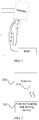
- an embodiment of the present invention provides an antenna 200, and a readable and writable storage unit 210 is installed inside the antenna 200.
- Configuration data and antenna information of the antenna may be written to the readable and writable storage unit 210 during production.
- the antenna information inside the readable and writable storage unit 210 includes information such as antenna frequency bands, antenna serial numbers, and configuration data of antennas of all models.
- an external reading and writing device 100 is installed outside the antenna 200.
- the external reading and writing device 100 performs read and write operations on the readable and writable storage unit 210 inside the antenna, first reads the antenna information, then retrieves the configuration data of the corresponding antenna 200 from the readable and writable storage unit 210 inside the antenna 200 according to information such as the antenna model in the antenna information, and then loads the configuration data to an external remote control unit RCU, thereby correctly adjusting the electrical down-tilt angle of the antenna.
- the external reading and writing device 100 may be a separate device, or may be built in a tower mounted device which is connected with the antenna, for example, an RCU, or a tower mounted amplifier (Tower Mounted Amplifier, TMA).
- a tower mounted amplifier Tower Mounted Amplifier, TMA
- a visualization window unit connected with the RCU and configured to obtain antenna information may be added.
- a query command is delivered through the visualization window unit to control the external reading and writing device to perform the operation of obtaining the antenna information, thereby easily and conveniently obtaining the required antenna information and configuring the antennas. If the configuration data of the antenna is changed later, the antenna configuration data of the readable and writable memory inside the antenna may also be changed through the visualization window unit.
- data may be communicated between the readable and writable storage unit 210 inside the antenna and the external reading module by using wired communication or wireless communication.
- data is communicated between the readable and writable storage unit 210 inside the antenna 200 and the external reading module 100 by using wireless communication.
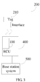
- the readable and writable storage unit inside the antenna is an electronic label RFID Tag 300.
- the external reading and writing device is optionally built in an RCU 400.
- the RCU 400 may obtain antenna information directly from the electronic label 300 of the antenna 200, read configuration data from the electronic label 300 according to the antenna information, and load the configuration data to the RCU 400.
- a base station system 500 may obtain, through a query command, information about the antenna connected with the RCU, or deliver a command to directly load the configuration data to the RCU.
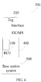
- a device connected with an antenna is connected with a storage chip board inside the antenna through connection wires to provide power supply and control signals required by the storage chip inside the antenna.
- Signal interfaces on the wires may be I2C or SPI interfaces.
- an external device can conveniently call the configuration data to configure the RCU, so that: 1. the RCU serial number and antenna information can be automatically recognized; for example, during project installation, it is not necessary to manually write down the RCU serial numbers and antenna information, a corresponding relationship between the RCU and the antenna is obtained by using a query function of the base station, and the configuration data in the storage unit inside the antenna is read and automatically loaded to the RCU; 2.
- the project installation time is reduced, and the error rate caused by manually writing down information is reduced; for example, the error rate of writing down and inputting information is inevitable, which is prone to mistakes, wastes time, and increases the cost; after this solution is used, the human mistakes will be avoided, and the project quality and installation efficiency will be improved; and 3. future maintenance is facilitated; for example, if an electrical tilting antenna is faulty and software or configuration data is lost, the configuration data needs to be loaded again, which requires mounting over the tower to write down RCU and corresponding information again; however, by using this solution, the antenna information corresponding to the RCU may be automatically obtained to acquire the configuration data, thereby achieving automatic loading.
- an antenna system 1 provided by an embodiment of the present invention includes an antenna apparatus 200, an external reading and writing device 100, and an RCU 400.
- the external reading and writing device 100 is built in the RCU 400.
- the antenna apparatus may be used in conjunction with an external remote control unit, and the antenna apparatus includes a phase shifter, a readable and writable memory, and a motor.
- the phase shifter is configured to adjust an electrical down-tilt angle of the antenna.
- the motor is configured to drive the phase shifter to move to adjust the electrical down-tilt angle of the antenna.
- the readable and writable memory is configured to store configuration data of the antenna and antenna information corresponding to the configuration data. When the configuration data is loaded to the RCU, the RCU drives the motor inside the antenna to move according to the configuration data, so as to drive the phase shifter inside the antenna to move, thereby adjusting the electrical down-tilt angle of the antenna.
- the external reading and writing device 100 is configured to perform read and write operations on the readable and writable storage unit 210 inside the antenna.
- the external reading and writing device 100 first reads the antenna information, then retrieves the configuration data of the antenna 200 from the readable and writable storage unit 210 according to the antenna information, and then loads the configuration data to the RCU 400.
- the antenna system 1 further includes a visualization window unit 600.
- a query command is delivered through the visualization window unit 600 to control the external reading and writing device 100 to obtain the antenna information.
- a readable and writable memory is disposed inside an antenna to store corresponding configuration data of the antenna, so that an external device can conveniently call the configuration data to configure the RCU and to remotely control the electrical down-tilt angle of the antenna. This reduces the human error rate, reduces the installation cost, improves the accuracy of project implementation, and facilitates maintenance.
- an embodiment of the present invention further provides an antenna electrical tilting method, including the following steps:
- the antenna information optionally includes one or more of all antenna models, antenna frequency bands, and antenna serial numbers, so that the RCU can obtain the configuration data of the corresponding antenna to be loaded to the RCU from the readable and writable memory according to the antenna models in the antenna information, or obtain the configuration data of the corresponding antenna to be loaded to the RCU according to the antenna frequency bands.
- a readable and writable memory is disposed inside an antenna to store corresponding configuration data of the antenna, so that an external device can conveniently call the configuration data to configure the RCU and to remotely control the electrical down-tilt angle of the antenna. This reduces the human error rate, reduces the installation cost, improves the accuracy of project implementation, and facilitates maintenance.
- the program may be stored in a computer readable storage medium.
- the storage medium may be a magnetic disk, an optical disk, a read-only memory (Read-Only Memory, ROM), or a random access memory (Random Access Memory, RAM).
Landscapes
- Engineering & Computer Science (AREA)
- Computer Networks & Wireless Communication (AREA)
- Variable-Direction Aerials And Aerial Arrays (AREA)
Applications Claiming Priority (3)
| Application Number | Priority Date | Filing Date | Title |
|---|---|---|---|
| CN201010555649.1A CN102136630B (zh) | 2010-11-23 | 2010-11-23 | 天线装置、天线系统和天线电调方法 |
| PCT/CN2011/078991 WO2012068913A1 (fr) | 2010-11-23 | 2011-08-26 | Dispositif d'antenne, système d'antenne et procédé électrique d'inclinaison d'antenne |
| EP11842575.0A EP2645476B1 (fr) | 2010-11-23 | 2011-08-26 | Dispositif d'antenne, système d'antenne et procédé électrique d'inclinaison d'antenne |
Related Parent Applications (2)
| Application Number | Title | Priority Date | Filing Date |
|---|---|---|---|
| EP11842575.0A Division EP2645476B1 (fr) | 2010-11-23 | 2011-08-26 | Dispositif d'antenne, système d'antenne et procédé électrique d'inclinaison d'antenne |
| EP11842575.0A Division-Into EP2645476B1 (fr) | 2010-11-23 | 2011-08-26 | Dispositif d'antenne, système d'antenne et procédé électrique d'inclinaison d'antenne |
Publications (2)
| Publication Number | Publication Date |
|---|---|
| EP3154127A1 true EP3154127A1 (fr) | 2017-04-12 |
| EP3154127B1 EP3154127B1 (fr) | 2020-08-12 |
Family
ID=44296325
Family Applications (5)
| Application Number | Title | Priority Date | Filing Date |
|---|---|---|---|
| EP20187279.3A Active EP3796473B1 (fr) | 2010-11-23 | 2011-08-26 | Appareil d'antenne, système d'antenne et procédé d'inclinaison électrique de l'antenne |
| EP16159539.2A Active EP3240108B1 (fr) | 2010-11-23 | 2011-08-26 | Appareil d'antenne, système d'antenne et procédé d'inclinaison électrique de l'antenne |
| EP23215438.5A Pending EP4358301A3 (fr) | 2010-11-23 | 2011-08-26 | Appareil d'antenne, système d'antenne et procédé d'inclinaison électrique d'antenne |
| EP11842575.0A Active EP2645476B1 (fr) | 2010-11-23 | 2011-08-26 | Dispositif d'antenne, système d'antenne et procédé électrique d'inclinaison d'antenne |
| EP16159540.0A Active EP3154127B1 (fr) | 2010-11-23 | 2011-08-26 | Appareil d'antenne, système d'antenne et procédé d'inclinaison électrique de l'antenne |
Family Applications Before (4)
| Application Number | Title | Priority Date | Filing Date |
|---|---|---|---|
| EP20187279.3A Active EP3796473B1 (fr) | 2010-11-23 | 2011-08-26 | Appareil d'antenne, système d'antenne et procédé d'inclinaison électrique de l'antenne |
| EP16159539.2A Active EP3240108B1 (fr) | 2010-11-23 | 2011-08-26 | Appareil d'antenne, système d'antenne et procédé d'inclinaison électrique de l'antenne |
| EP23215438.5A Pending EP4358301A3 (fr) | 2010-11-23 | 2011-08-26 | Appareil d'antenne, système d'antenne et procédé d'inclinaison électrique d'antenne |
| EP11842575.0A Active EP2645476B1 (fr) | 2010-11-23 | 2011-08-26 | Dispositif d'antenne, système d'antenne et procédé électrique d'inclinaison d'antenne |
Country Status (7)
| Country | Link |
|---|---|
| US (6) | US9653798B2 (fr) |
| EP (5) | EP3796473B1 (fr) |
| CN (2) | CN104966902B (fr) |
| DE (1) | DE202011110812U1 (fr) |
| ES (1) | ES2588308T3 (fr) |
| PL (1) | PL2645476T3 (fr) |
| WO (1) | WO2012068913A1 (fr) |
Families Citing this family (22)
| Publication number | Priority date | Publication date | Assignee | Title |
|---|---|---|---|---|
| CN104966902B (zh) | 2010-11-23 | 2017-11-21 | 华为技术有限公司 | 天线装置、天线系统和天线电调方法 |
| DE102011015572B3 (de) | 2011-03-30 | 2012-06-28 | Kathrein-Werke Kg | Strahlformeinrichtung für eine Antenne sowie zugehörige Antenne |
| CN102544731A (zh) * | 2012-02-08 | 2012-07-04 | 华为技术有限公司 | 一种天线系统与装置 |
| CN102905279B (zh) * | 2012-09-28 | 2015-06-03 | 华为技术有限公司 | 远端控制单元序列号和天线扇区号的匹配方法及装置 |
| CN105591204B (zh) * | 2013-07-26 | 2018-12-14 | 上海华为技术有限公司 | 一种天线阵列控制装置、方法以及系统 |
| US10181656B2 (en) * | 2013-10-21 | 2019-01-15 | Commscope Technologies Llc | Antenna detection with non-volatile memory powered by DC over coaxial cable |
| US9300043B2 (en) * | 2014-02-20 | 2016-03-29 | Adam Houtman | Multiple frequency range antenna |
| CN103874080A (zh) | 2014-03-31 | 2014-06-18 | 深圳市华为安捷信电气有限公司 | 匹配方法及装置 |
| CN103915687B (zh) * | 2014-04-10 | 2016-04-27 | 四川九洲电器集团有限责任公司 | 一种三坐标相控阵雷达天线tr组件编号自动识别方法 |
| WO2016106415A2 (fr) | 2014-12-24 | 2016-06-30 | Ubiquiti Networks, Inc. | Dispositif de mise en réseau compact destiné à des stations à distance |
| CN107615586B (zh) | 2015-05-26 | 2020-02-14 | 华为技术有限公司 | 一种电调装置、天线及电调方法 |
| US9722864B2 (en) * | 2015-06-26 | 2017-08-01 | Intel Corporation | Systems, methods, and apparatus to configure embedded devices |
| CN106330345B (zh) * | 2015-06-29 | 2020-03-06 | 中兴通讯股份有限公司 | 一种检测电调天线连接线序的方法和装置 |
| DE102017001543A1 (de) | 2017-02-16 | 2018-08-16 | Kathrein-Werke Kg | Antenne, insbesondere Mobilfunkantenne |
| CN110462927B (zh) * | 2017-03-31 | 2021-09-14 | 华为技术有限公司 | 天线下倾角调节装置及通信设备 |
| CN109101044A (zh) * | 2018-08-03 | 2018-12-28 | 广州瀚信通信科技股份有限公司 | 一种基于物联网技术的天线信息采集及调整系统 |
| CN110970731A (zh) * | 2018-09-30 | 2020-04-07 | 华为技术有限公司 | 调节装置、天线及通信设备 |
| CN111224722B (zh) * | 2018-11-27 | 2021-10-26 | 华为技术有限公司 | 天线头端的检测方法及装置 |
| CN110177009B (zh) * | 2019-04-30 | 2022-04-19 | 武汉虹信科技发展有限责任公司 | 远端控制单元的电机序列号配置方法及装置 |
| CN110690572B (zh) * | 2019-09-12 | 2020-11-24 | 广东盛路通信科技股份有限公司 | 一种基于stm32f0微控制器的天线倾角调节控制方法 |
| US11304069B2 (en) * | 2019-11-27 | 2022-04-12 | Commscope Technologies Llc | Base station antennas having field-enabled remote electronic tilt capabilities |
| CN114335979B (zh) * | 2021-12-30 | 2023-01-10 | 深圳市鑫恒阳科技有限公司 | 一种用于通信基站的5g天线 |
Citations (4)
| Publication number | Priority date | Publication date | Assignee | Title |
|---|---|---|---|---|
| WO2003079484A2 (fr) * | 2002-03-15 | 2003-09-25 | Andrew Corp. | Protocole interface antenne |
| US20060066494A1 (en) * | 2003-02-24 | 2006-03-30 | Zdenek Trejtnar | Radiocommunications antenna with misalignment of radiation lobe by variable phase shifter |
| WO2006057613A1 (fr) * | 2004-11-26 | 2006-06-01 | Powerwave Technologies Sweden Ab | Systeme de controle d'antenne |
| EP1962374A1 (fr) * | 2007-02-21 | 2008-08-27 | Lucent Technologies Inc. | Identification d'antennes par câbles |
Family Cites Families (34)
| Publication number | Priority date | Publication date | Assignee | Title |
|---|---|---|---|---|
| US4888592A (en) * | 1988-09-28 | 1989-12-19 | General Instrument Corporation | Satellite antenna alignment system |
| CN1316835C (zh) | 1994-11-04 | 2007-05-16 | 安德鲁公司 | 天线控制系统 |
| US6075330A (en) * | 1997-11-07 | 2000-06-13 | Terk Technologies Corp. | Outdoor antenna system with remote control and method for optimizing antenna function |
| US7586398B2 (en) * | 1998-07-23 | 2009-09-08 | Universal Electronics, Inc. | System and method for setting up a universal remote control |
| US6239744B1 (en) | 1999-06-30 | 2001-05-29 | Radio Frequency Systems, Inc. | Remote tilt antenna system |
| FR2806838B1 (fr) * | 2000-03-27 | 2003-07-18 | Mitsubishi Electric Inf Tech | Procede de commande dynamique d'inclinaison d'antenne pour un systeme de radiotelecommunication |
| KR20090033403A (ko) * | 2000-07-10 | 2009-04-02 | 앤드류 코포레이션 | 셀룰러 안테나 |
| DE10104564C1 (de) * | 2001-02-01 | 2002-09-19 | Kathrein Werke Kg | Steuerungsvorrichtung zum Einstellen eines unterschiedlichen Absenkwinkels insbesondere von zu einer Basisstation gehörenden Mobilfunkantennen sowie eine zugehörige Antenne und Verfahren zur Veränderung eines Absenkwinkels |
| US6931261B2 (en) * | 2001-08-27 | 2005-08-16 | Interwave Communications International Ltd. | Tower top cellular communication devices and method for operating the same |
| US7286844B1 (en) * | 2003-01-31 | 2007-10-23 | Bbn Technologies Corp. | Systems and methods for three dimensional antenna selection and power control in an Ad-Hoc wireless network |
| US7085541B2 (en) * | 2003-01-31 | 2006-08-01 | Bbnt Solutions Llc | Systems and methods for directional antenna power control in a wireless network |
| US7427962B2 (en) * | 2003-06-16 | 2008-09-23 | Andrew Corporation | Base station antenna rotation mechanism |
| US20050003873A1 (en) * | 2003-07-01 | 2005-01-06 | Netro Corporation | Directional indicator for antennas |
| US20060066443A1 (en) * | 2004-09-15 | 2006-03-30 | Tagsys Sa | Self-adjusting RF assembly |
| SE528018C2 (sv) | 2004-11-26 | 2006-08-08 | Powerwave Technologies Sweden | Antennstyrsystem |
| JP4513974B2 (ja) * | 2005-06-27 | 2010-07-28 | 日本電気株式会社 | 優先度の高い情報を同報する無線通信ネットワーク、その変更方法、及び無線通信ネットワーク設計ツール |
| US7652634B2 (en) * | 2005-09-01 | 2010-01-26 | Dell Products L.P. | Antenna with integrated parameter storage |
| JP2007249488A (ja) * | 2006-03-15 | 2007-09-27 | Nec Corp | Rfidシステム、rfid読取方法 |
| CN2872622Y (zh) * | 2006-03-23 | 2007-02-21 | 京信通信技术(广州)有限公司 | 调整移动通信天线电下倾角的控制装置 |
| CN1983857A (zh) * | 2006-04-05 | 2007-06-20 | 华为技术有限公司 | 一种天线设备的参数配置方法和装置 |
| SE529953C2 (sv) * | 2006-05-31 | 2008-01-15 | Powerwave Technologies Sweden | Styrsystem för styrning av den elektriskt inställda lutningen hos en antenn |
| US7812776B2 (en) * | 2006-12-19 | 2010-10-12 | Radiacion Y Microondas, S.A. | Remote control device for controlling the angle of inclination of the radiation diagram on an antenna |
| US8515494B2 (en) * | 2007-01-13 | 2013-08-20 | Panasonic Automotive Systems Company Of America, Division Of Panasonic Corporation Of North America | Highly configurable radio frequency (RF) module |
| WO2008154514A2 (fr) * | 2007-06-08 | 2008-12-18 | Sunsight Holdings, Llc | Outil d'alignement pour antennes directionnelles |
| US20090141623A1 (en) * | 2007-11-27 | 2009-06-04 | Hyun Jung | Central Antenna Management System With Centralized Database |
| KR100960003B1 (ko) | 2007-11-30 | 2010-05-28 | 주식회사 에이스테크놀로지 | 안테나에 있어서 경사각 조정 장치 |
| US20090146894A1 (en) * | 2007-12-05 | 2009-06-11 | Honeywell International Inc. | Reconfigurable antenna steering patterns |
| CN102187597B (zh) * | 2008-08-20 | 2014-09-10 | 株式会社Kmw | 用于移动通信基站的天线的控制系统和图像数据提供系统以及使用该控制系统的方法 |
| CN201397879Y (zh) * | 2009-01-09 | 2010-02-03 | 东莞市晖速天线技术有限公司 | 一种用于调整移动通信天线电下倾角的装置 |
| KR101567882B1 (ko) * | 2009-05-11 | 2015-11-12 | 주식회사 케이엠더블유 | 수직 빔틸트 제어 안테나를 위한 다중 이상기 |
| CN104966902B (zh) | 2010-11-23 | 2017-11-21 | 华为技术有限公司 | 天线装置、天线系统和天线电调方法 |
| DE102011015572B3 (de) * | 2011-03-30 | 2012-06-28 | Kathrein-Werke Kg | Strahlformeinrichtung für eine Antenne sowie zugehörige Antenne |
| US10181656B2 (en) * | 2013-10-21 | 2019-01-15 | Commscope Technologies Llc | Antenna detection with non-volatile memory powered by DC over coaxial cable |
| US11096068B1 (en) * | 2015-10-22 | 2021-08-17 | Atavious F. Burt | Panel antenna monitoring |
-
2010
- 2010-11-23 CN CN201510377470.4A patent/CN104966902B/zh active Active
- 2010-11-23 CN CN201010555649.1A patent/CN102136630B/zh active Active
-
2011
- 2011-08-26 WO PCT/CN2011/078991 patent/WO2012068913A1/fr not_active Ceased
- 2011-08-26 EP EP20187279.3A patent/EP3796473B1/fr active Active
- 2011-08-26 DE DE202011110812.4U patent/DE202011110812U1/de not_active Expired - Lifetime
- 2011-08-26 ES ES11842575.0T patent/ES2588308T3/es active Active
- 2011-08-26 EP EP16159539.2A patent/EP3240108B1/fr active Active
- 2011-08-26 EP EP23215438.5A patent/EP4358301A3/fr active Pending
- 2011-08-26 EP EP11842575.0A patent/EP2645476B1/fr active Active
- 2011-08-26 EP EP16159540.0A patent/EP3154127B1/fr active Active
- 2011-08-26 PL PL11842575.0T patent/PL2645476T3/pl unknown
-
2013
- 2013-01-11 US US13/740,064 patent/US9653798B2/en active Active
-
2014
- 2014-10-15 US US14/514,811 patent/US9496607B2/en active Active
-
2016
- 2016-11-17 US US15/354,888 patent/US10122082B2/en active Active
-
2018
- 2018-10-22 US US16/166,831 patent/US10756427B2/en active Active
-
2020
- 2020-08-05 US US16/985,658 patent/US11552394B2/en active Active
-
2022
- 2022-12-09 US US18/063,933 patent/US12463336B2/en active Active
Patent Citations (4)
| Publication number | Priority date | Publication date | Assignee | Title |
|---|---|---|---|---|
| WO2003079484A2 (fr) * | 2002-03-15 | 2003-09-25 | Andrew Corp. | Protocole interface antenne |
| US20060066494A1 (en) * | 2003-02-24 | 2006-03-30 | Zdenek Trejtnar | Radiocommunications antenna with misalignment of radiation lobe by variable phase shifter |
| WO2006057613A1 (fr) * | 2004-11-26 | 2006-06-01 | Powerwave Technologies Sweden Ab | Systeme de controle d'antenne |
| EP1962374A1 (fr) * | 2007-02-21 | 2008-08-27 | Lucent Technologies Inc. | Identification d'antennes par câbles |
Also Published As
| Publication number | Publication date |
|---|---|
| US10122082B2 (en) | 2018-11-06 |
| US11552394B2 (en) | 2023-01-10 |
| US20190058250A1 (en) | 2019-02-21 |
| US20130127666A1 (en) | 2013-05-23 |
| EP3240108B1 (fr) | 2020-08-19 |
| CN102136630B (zh) | 2015-06-03 |
| US20210021027A1 (en) | 2021-01-21 |
| CN104966902B (zh) | 2017-11-21 |
| EP2645476A4 (fr) | 2013-11-06 |
| CN102136630A (zh) | 2011-07-27 |
| DE202011110812U1 (de) | 2016-07-18 |
| EP4358301A2 (fr) | 2024-04-24 |
| EP2645476B1 (fr) | 2016-06-01 |
| EP3796473B1 (fr) | 2024-01-10 |
| US9653798B2 (en) | 2017-05-16 |
| US12463336B2 (en) | 2025-11-04 |
| EP4358301A3 (fr) | 2024-07-03 |
| US20150029057A1 (en) | 2015-01-29 |
| US9496607B2 (en) | 2016-11-15 |
| ES2588308T3 (es) | 2016-11-02 |
| EP3240108A1 (fr) | 2017-11-01 |
| CN104966902A (zh) | 2015-10-07 |
| US10756427B2 (en) | 2020-08-25 |
| US20170069968A1 (en) | 2017-03-09 |
| EP2645476A1 (fr) | 2013-10-02 |
| WO2012068913A1 (fr) | 2012-05-31 |
| PL2645476T3 (pl) | 2016-12-30 |
| EP3796473A1 (fr) | 2021-03-24 |
| EP3154127B1 (fr) | 2020-08-12 |
| US20230178886A1 (en) | 2023-06-08 |
Similar Documents
| Publication | Publication Date | Title |
|---|---|---|
| US12463336B2 (en) | Antenna apparatus, antenna system, and antenna electrical tilting method | |
| EP3618021B1 (fr) | Dispositif et procédé de commande à distance pour véhicule à conduite automatique et serveur | |
| US20110105099A1 (en) | Antenna line device configuration system | |
| CN102751574B (zh) | 电调装置、电调控制系统及电调控制方法 | |
| CN102456948B (zh) | 电调天线的控制方法及系统、电调天线控制器及维护终端 | |
| EP3477985A1 (fr) | Système de point d'accès sans fil, dispositif électronique portable pouvant commander une direction d'antenne d'appareil de point d'accès sans fil et procédé d'optimisation de la direction d'antenne d'un appareil de point d'accès sans fil | |
| CN102752775B (zh) | 一种智能天线参数配置的发送和接收方法及装置 | |
| US10290204B2 (en) | Maintenance system and method for maintenance of a door arrangement | |
| CN111129776B (zh) | 用于基站天线的电调控制系统及其电调方法 | |
| CN202495572U (zh) | 一种天线系统与装置 | |
| CN105487412B (zh) | 一种获取远程电调天线控制单元级联的方法和系统 | |
| EP4179454B1 (fr) | Procédé d'étalonnage de données et pilote | |
| CN118673939A (zh) | 一种熔纤盘及端口跳纤的电子标签id的采集装置 | |
| WO2024175203A1 (fr) | Procédé de vérification d'accouplement de câble d'une antenne multibande | |
| CN118907709A (zh) | 一种基于机器视觉的多功能智能盘点装置及方法 | |
| CN114064180A (zh) | 一种基于无源rfid的安措可视化操作指引系统与方法 |
Legal Events
| Date | Code | Title | Description |
|---|---|---|---|
| PUAI | Public reference made under article 153(3) epc to a published international application that has entered the european phase |
Free format text: ORIGINAL CODE: 0009012 |
|
| STAA | Information on the status of an ep patent application or granted ep patent |
Free format text: STATUS: THE APPLICATION HAS BEEN PUBLISHED |
|
| AC | Divisional application: reference to earlier application |
Ref document number: 2645476 Country of ref document: EP Kind code of ref document: P |
|
| AK | Designated contracting states |
Kind code of ref document: A1 Designated state(s): AL AT BE BG CH CY CZ DE DK EE ES FI FR GB GR HR HU IE IS IT LI LT LU LV MC MK MT NL NO PL PT RO RS SE SI SK SM TR |
|
| STAA | Information on the status of an ep patent application or granted ep patent |
Free format text: STATUS: REQUEST FOR EXAMINATION WAS MADE |
|
| 17P | Request for examination filed |
Effective date: 20171012 |
|
| RBV | Designated contracting states (corrected) |
Designated state(s): AL AT BE BG CH CY CZ DE DK EE ES FI FR GB GR HR HU IE IS IT LI LT LU LV MC MK MT NL NO PL PT RO RS SE SI SK SM TR |
|
| STAA | Information on the status of an ep patent application or granted ep patent |
Free format text: STATUS: EXAMINATION IS IN PROGRESS |
|
| 17Q | First examination report despatched |
Effective date: 20180730 |
|
| RIC1 | Information provided on ipc code assigned before grant |
Ipc: H01Q 3/32 20060101AFI20200122BHEP Ipc: H04W 16/28 20090101ALN20200122BHEP Ipc: H01Q 1/24 20060101ALI20200122BHEP Ipc: H01Q 3/00 20060101ALI20200122BHEP Ipc: H01Q 3/06 20060101ALI20200122BHEP |
|
| GRAP | Despatch of communication of intention to grant a patent |
Free format text: ORIGINAL CODE: EPIDOSNIGR1 |
|
| STAA | Information on the status of an ep patent application or granted ep patent |
Free format text: STATUS: GRANT OF PATENT IS INTENDED |
|
| RIC1 | Information provided on ipc code assigned before grant |
Ipc: H01Q 1/24 20060101ALI20200211BHEP Ipc: H01Q 3/32 20060101AFI20200211BHEP Ipc: H01Q 3/00 20060101ALI20200211BHEP Ipc: H04W 16/28 20090101ALN20200211BHEP Ipc: H01Q 3/06 20060101ALI20200211BHEP |
|
| INTG | Intention to grant announced |
Effective date: 20200228 |
|
| RAP1 | Party data changed (applicant data changed or rights of an application transferred) |
Owner name: HUAWEI TECHNOLOGIES CO., LTD. |
|
| GRAS | Grant fee paid |
Free format text: ORIGINAL CODE: EPIDOSNIGR3 |
|
| GRAA | (expected) grant |
Free format text: ORIGINAL CODE: 0009210 |
|
| STAA | Information on the status of an ep patent application or granted ep patent |
Free format text: STATUS: THE PATENT HAS BEEN GRANTED |
|
| AC | Divisional application: reference to earlier application |
Ref document number: 2645476 Country of ref document: EP Kind code of ref document: P |
|
| AK | Designated contracting states |
Kind code of ref document: B1 Designated state(s): AL AT BE BG CH CY CZ DE DK EE ES FI FR GB GR HR HU IE IS IT LI LT LU LV MC MK MT NL NO PL PT RO RS SE SI SK SM TR |
|
| REG | Reference to a national code |
Ref country code: CH Ref legal event code: EP |
|
| REG | Reference to a national code |
Ref country code: IE Ref legal event code: FG4D |
|
| REG | Reference to a national code |
Ref country code: DE Ref legal event code: R096 Ref document number: 602011068224 Country of ref document: DE |
|
| REG | Reference to a national code |
Ref country code: AT Ref legal event code: REF Ref document number: 1302453 Country of ref document: AT Kind code of ref document: T Effective date: 20200915 |
|
| REG | Reference to a national code |
Ref country code: LT Ref legal event code: MG4D |
|
| REG | Reference to a national code |
Ref country code: NL Ref legal event code: MP Effective date: 20200812 |
|
| PG25 | Lapsed in a contracting state [announced via postgrant information from national office to epo] |
Ref country code: NO Free format text: LAPSE BECAUSE OF FAILURE TO SUBMIT A TRANSLATION OF THE DESCRIPTION OR TO PAY THE FEE WITHIN THE PRESCRIBED TIME-LIMIT Effective date: 20201112 Ref country code: GR Free format text: LAPSE BECAUSE OF FAILURE TO SUBMIT A TRANSLATION OF THE DESCRIPTION OR TO PAY THE FEE WITHIN THE PRESCRIBED TIME-LIMIT Effective date: 20201113 Ref country code: SE Free format text: LAPSE BECAUSE OF FAILURE TO SUBMIT A TRANSLATION OF THE DESCRIPTION OR TO PAY THE FEE WITHIN THE PRESCRIBED TIME-LIMIT Effective date: 20200812 Ref country code: HR Free format text: LAPSE BECAUSE OF FAILURE TO SUBMIT A TRANSLATION OF THE DESCRIPTION OR TO PAY THE FEE WITHIN THE PRESCRIBED TIME-LIMIT Effective date: 20200812 Ref country code: LT Free format text: LAPSE BECAUSE OF FAILURE TO SUBMIT A TRANSLATION OF THE DESCRIPTION OR TO PAY THE FEE WITHIN THE PRESCRIBED TIME-LIMIT Effective date: 20200812 Ref country code: FI Free format text: LAPSE BECAUSE OF FAILURE TO SUBMIT A TRANSLATION OF THE DESCRIPTION OR TO PAY THE FEE WITHIN THE PRESCRIBED TIME-LIMIT Effective date: 20200812 Ref country code: BG Free format text: LAPSE BECAUSE OF FAILURE TO SUBMIT A TRANSLATION OF THE DESCRIPTION OR TO PAY THE FEE WITHIN THE PRESCRIBED TIME-LIMIT Effective date: 20201112 |
|
| PG25 | Lapsed in a contracting state [announced via postgrant information from national office to epo] |
Ref country code: NL Free format text: LAPSE BECAUSE OF FAILURE TO SUBMIT A TRANSLATION OF THE DESCRIPTION OR TO PAY THE FEE WITHIN THE PRESCRIBED TIME-LIMIT Effective date: 20200812 Ref country code: RS Free format text: LAPSE BECAUSE OF FAILURE TO SUBMIT A TRANSLATION OF THE DESCRIPTION OR TO PAY THE FEE WITHIN THE PRESCRIBED TIME-LIMIT Effective date: 20200812 Ref country code: PL Free format text: LAPSE BECAUSE OF FAILURE TO SUBMIT A TRANSLATION OF THE DESCRIPTION OR TO PAY THE FEE WITHIN THE PRESCRIBED TIME-LIMIT Effective date: 20200812 Ref country code: LV Free format text: LAPSE BECAUSE OF FAILURE TO SUBMIT A TRANSLATION OF THE DESCRIPTION OR TO PAY THE FEE WITHIN THE PRESCRIBED TIME-LIMIT Effective date: 20200812 Ref country code: IS Free format text: LAPSE BECAUSE OF FAILURE TO SUBMIT A TRANSLATION OF THE DESCRIPTION OR TO PAY THE FEE WITHIN THE PRESCRIBED TIME-LIMIT Effective date: 20201212 |
|
| REG | Reference to a national code |
Ref country code: DE Ref legal event code: R119 Ref document number: 602011068224 Country of ref document: DE |
|
| REG | Reference to a national code |
Ref country code: CH Ref legal event code: PL |
|
| PG25 | Lapsed in a contracting state [announced via postgrant information from national office to epo] |
Ref country code: EE Free format text: LAPSE BECAUSE OF FAILURE TO SUBMIT A TRANSLATION OF THE DESCRIPTION OR TO PAY THE FEE WITHIN THE PRESCRIBED TIME-LIMIT Effective date: 20200812 Ref country code: SM Free format text: LAPSE BECAUSE OF FAILURE TO SUBMIT A TRANSLATION OF THE DESCRIPTION OR TO PAY THE FEE WITHIN THE PRESCRIBED TIME-LIMIT Effective date: 20200812 Ref country code: RO Free format text: LAPSE BECAUSE OF FAILURE TO SUBMIT A TRANSLATION OF THE DESCRIPTION OR TO PAY THE FEE WITHIN THE PRESCRIBED TIME-LIMIT Effective date: 20200812 Ref country code: LU Free format text: LAPSE BECAUSE OF NON-PAYMENT OF DUE FEES Effective date: 20200826 Ref country code: LI Free format text: LAPSE BECAUSE OF NON-PAYMENT OF DUE FEES Effective date: 20200831 Ref country code: CZ Free format text: LAPSE BECAUSE OF FAILURE TO SUBMIT A TRANSLATION OF THE DESCRIPTION OR TO PAY THE FEE WITHIN THE PRESCRIBED TIME-LIMIT Effective date: 20200812 Ref country code: DK Free format text: LAPSE BECAUSE OF FAILURE TO SUBMIT A TRANSLATION OF THE DESCRIPTION OR TO PAY THE FEE WITHIN THE PRESCRIBED TIME-LIMIT Effective date: 20200812 Ref country code: CH Free format text: LAPSE BECAUSE OF NON-PAYMENT OF DUE FEES Effective date: 20200831 |
|
| REG | Reference to a national code |
Ref country code: AT Ref legal event code: UEP Ref document number: 1302453 Country of ref document: AT Kind code of ref document: T Effective date: 20200812 |
|
| REG | Reference to a national code |
Ref country code: BE Ref legal event code: MM Effective date: 20200831 |
|
| PG25 | Lapsed in a contracting state [announced via postgrant information from national office to epo] |
Ref country code: MC Free format text: LAPSE BECAUSE OF FAILURE TO SUBMIT A TRANSLATION OF THE DESCRIPTION OR TO PAY THE FEE WITHIN THE PRESCRIBED TIME-LIMIT Effective date: 20200812 Ref country code: AL Free format text: LAPSE BECAUSE OF FAILURE TO SUBMIT A TRANSLATION OF THE DESCRIPTION OR TO PAY THE FEE WITHIN THE PRESCRIBED TIME-LIMIT Effective date: 20200812 Ref country code: ES Free format text: LAPSE BECAUSE OF FAILURE TO SUBMIT A TRANSLATION OF THE DESCRIPTION OR TO PAY THE FEE WITHIN THE PRESCRIBED TIME-LIMIT Effective date: 20200812 |
|
| PLBE | No opposition filed within time limit |
Free format text: ORIGINAL CODE: 0009261 |
|
| STAA | Information on the status of an ep patent application or granted ep patent |
Free format text: STATUS: NO OPPOSITION FILED WITHIN TIME LIMIT |
|
| PG25 | Lapsed in a contracting state [announced via postgrant information from national office to epo] |
Ref country code: SK Free format text: LAPSE BECAUSE OF FAILURE TO SUBMIT A TRANSLATION OF THE DESCRIPTION OR TO PAY THE FEE WITHIN THE PRESCRIBED TIME-LIMIT Effective date: 20200812 |
|
| 26N | No opposition filed |
Effective date: 20210514 |
|
| GBPC | Gb: european patent ceased through non-payment of renewal fee |
Effective date: 20201112 |
|
| PG25 | Lapsed in a contracting state [announced via postgrant information from national office to epo] |
Ref country code: DE Free format text: LAPSE BECAUSE OF NON-PAYMENT OF DUE FEES Effective date: 20210302 Ref country code: FR Free format text: LAPSE BECAUSE OF NON-PAYMENT OF DUE FEES Effective date: 20201012 Ref country code: IT Free format text: LAPSE BECAUSE OF FAILURE TO SUBMIT A TRANSLATION OF THE DESCRIPTION OR TO PAY THE FEE WITHIN THE PRESCRIBED TIME-LIMIT Effective date: 20200812 |
|
| PG25 | Lapsed in a contracting state [announced via postgrant information from national office to epo] |
Ref country code: SI Free format text: LAPSE BECAUSE OF FAILURE TO SUBMIT A TRANSLATION OF THE DESCRIPTION OR TO PAY THE FEE WITHIN THE PRESCRIBED TIME-LIMIT Effective date: 20200812 Ref country code: IE Free format text: LAPSE BECAUSE OF NON-PAYMENT OF DUE FEES Effective date: 20200826 Ref country code: BE Free format text: LAPSE BECAUSE OF NON-PAYMENT OF DUE FEES Effective date: 20200831 |
|
| PG25 | Lapsed in a contracting state [announced via postgrant information from national office to epo] |
Ref country code: GB Free format text: LAPSE BECAUSE OF NON-PAYMENT OF DUE FEES Effective date: 20201112 |
|
| PG25 | Lapsed in a contracting state [announced via postgrant information from national office to epo] |
Ref country code: IS Free format text: LAPSE BECAUSE OF FAILURE TO SUBMIT A TRANSLATION OF THE DESCRIPTION OR TO PAY THE FEE WITHIN THE PRESCRIBED TIME-LIMIT Effective date: 20201212 Ref country code: TR Free format text: LAPSE BECAUSE OF FAILURE TO SUBMIT A TRANSLATION OF THE DESCRIPTION OR TO PAY THE FEE WITHIN THE PRESCRIBED TIME-LIMIT Effective date: 20200812 Ref country code: MT Free format text: LAPSE BECAUSE OF FAILURE TO SUBMIT A TRANSLATION OF THE DESCRIPTION OR TO PAY THE FEE WITHIN THE PRESCRIBED TIME-LIMIT Effective date: 20200812 Ref country code: CY Free format text: LAPSE BECAUSE OF FAILURE TO SUBMIT A TRANSLATION OF THE DESCRIPTION OR TO PAY THE FEE WITHIN THE PRESCRIBED TIME-LIMIT Effective date: 20200812 |
|
| PG25 | Lapsed in a contracting state [announced via postgrant information from national office to epo] |
Ref country code: MK Free format text: LAPSE BECAUSE OF FAILURE TO SUBMIT A TRANSLATION OF THE DESCRIPTION OR TO PAY THE FEE WITHIN THE PRESCRIBED TIME-LIMIT Effective date: 20200812 |
|
| PG25 | Lapsed in a contracting state [announced via postgrant information from national office to epo] |
Ref country code: PT Free format text: LAPSE BECAUSE OF FAILURE TO SUBMIT A TRANSLATION OF THE DESCRIPTION OR TO PAY THE FEE WITHIN THE PRESCRIBED TIME-LIMIT Effective date: 20200812 |
|
| P01 | Opt-out of the competence of the unified patent court (upc) registered |
Effective date: 20230514 |
|
| PGFP | Annual fee paid to national office [announced via postgrant information from national office to epo] |
Ref country code: AT Payment date: 20250725 Year of fee payment: 15 |