EP3154207B1 - Konzentrator - Google Patents
Konzentrator Download PDFInfo
- Publication number
- EP3154207B1 EP3154207B1 EP14893755.0A EP14893755A EP3154207B1 EP 3154207 B1 EP3154207 B1 EP 3154207B1 EP 14893755 A EP14893755 A EP 14893755A EP 3154207 B1 EP3154207 B1 EP 3154207B1
- Authority
- EP
- European Patent Office
- Prior art keywords
- sidewall
- antenna
- concentrator
- communication module
- wireless communication
- Prior art date
- Legal status (The legal status is an assumption and is not a legal conclusion. Google has not performed a legal analysis and makes no representation as to the accuracy of the status listed.)
- Active
Links
Images


Classifications
-
- H—ELECTRICITY
- H04—ELECTRIC COMMUNICATION TECHNIQUE
- H04Q—SELECTING
- H04Q9/00—Arrangements in telecontrol or telemetry systems for selectively calling a substation from a main station, in which substation desired apparatus is selected for applying a control signal thereto or for obtaining measured values therefrom
-
- G—PHYSICS
- G08—SIGNALLING
- G08C—TRANSMISSION SYSTEMS FOR MEASURED VALUES, CONTROL OR SIMILAR SIGNALS
- G08C15/00—Arrangements characterised by the use of multiplexing for the transmission of a plurality of signals over a common path
-
- G—PHYSICS
- G08—SIGNALLING
- G08C—TRANSMISSION SYSTEMS FOR MEASURED VALUES, CONTROL OR SIMILAR SIGNALS
- G08C17/00—Arrangements for transmitting signals characterised by the use of a wireless electrical link
-
- H—ELECTRICITY
- H01—ELECTRIC ELEMENTS
- H01Q—ANTENNAS, i.e. RADIO AERIALS
- H01Q1/00—Details of, or arrangements associated with, antennas
- H01Q1/42—Housings not intimately mechanically associated with radiating elements, e.g. radome
-
- H—ELECTRICITY
- H04—ELECTRIC COMMUNICATION TECHNIQUE
- H04B—TRANSMISSION
- H04B7/00—Radio transmission systems, i.e. using radiation field
- H04B7/02—Diversity systems; Multi-antenna system, i.e. transmission or reception using multiple antennas
-
- H—ELECTRICITY
- H04—ELECTRIC COMMUNICATION TECHNIQUE
- H04Q—SELECTING
- H04Q2209/00—Arrangements in telecontrol or telemetry systems
- H04Q2209/40—Arrangements in telecontrol or telemetry systems using a wireless architecture
-
- H—ELECTRICITY
- H04—ELECTRIC COMMUNICATION TECHNIQUE
- H04Q—SELECTING
- H04Q2209/00—Arrangements in telecontrol or telemetry systems
- H04Q2209/60—Arrangements in telecontrol or telemetry systems for transmitting utility meters data, i.e. transmission of data from the reader of the utility meter
Definitions
- Embodiments described herein relate generally to a concentrator.
- WO 99/21147 A1 discloses a communication system configured to transmit data between a plurality of locations.
- the communication system is suitable for use by a utility provider to monitor a plurality of metering devices from a remote location.
- the communication system comprises a controller for a least receiving data, a plurality of metering devices arranged in a defined number of metering groups for transmitting data associated with an amount of usage of a utility, and a defined number of concentrators, each operably connected to the controller and one metering group for transmission of data between the control and plurality of metering devices.
- An electric power meter having a communication function to measure an amount of electric power consumption digitally and notify a power company of the measured amount of electric power consumption by using a communication line (a so-called smart meter) is about to be introduced.
- the smart meter notifies a concentrator of the measured amount of electric power consumption.
- the concentrator is notified of amounts of electric power consumption by several hundred smart meters.
- the concentrator notifies the power company of the amount of electric power consumption measured by each smart meter.
- Patent Literature 1 WO 2012/042748
- the concentrator notifies a server of the amount of electric power consumption of each household by, for example, a wireless communication of a cellular scheme.
- the concentrator is provided on the back surface of the smart meter. Since the smart meter has metal components such as a transformer, degradation in antenna performance is expected.
- the invention aims to provide a concentrator capable of reducing the degradation in antenna performance.
- a concentrator having a first surface on which a measuring device, which measures an amount of electric power consumption, is arranged includes a housing, a communication module, a wireless communication module, a control module, a first antenna, and a second antenna.
- the housing includes a first sidewall and a second sidewall which are opposed in a first direction orthogonal to a direction of arrangement of the measuring device and the concentrator, the first sidewall and the second sidewall being connected to the first surface.
- the communication module is provided in the housing for receiving amounts of electric power consumption from measuring devices including the measuring device.
- the wireless communication module is provided in the housing.
- the control module notifies a server of the amounts of electric power consumption by using the wireless communication module.
- the first antenna is provided in proximity to the first sidewall.
- the second antenna is provided in proximity to the second sidewall.
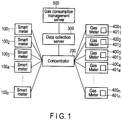
- FIG. 1 shows a configuration of a smart meter system.
- Each of the smart meters 100 1 , 100 2 , 100 3 , ... , 100 n notifies a concentrator 200 of an amount of half-hour electric power consumption.
- the concentrator 200 notifies a data collection server 300 of the amounts of electric power consumption.
- the data collection server 300 analyzes the amounts of electric power consumption, thereby providing services to set electric power charge or to facilitate efficient energy use.
- the smart meter system may be used by a gas meter system.
- wireless communication devices 401 1 , 401 2 , 401 3 , ... , 401 n are provided in gas meters 400 1 , 400 2 , 400 3 , ... , 400 n which measure amounts of gas consumption.
- the wireless communication devices 401 1 , 401 2 , 401 3 , ... , 401 n transmit the measured amounts of gas consumption (meter reading data) to the concentrator 200.
- the gas meters or wireless communication devices 401 1 , 401 2 , 401 3 , ... , 401 n should preferably encrypt gas consumption data.
- the concentrator 200 transmits the amounts of gas and electric power consumption to the data collection server 300.
- the data collection server 300 extracts gas consumption data from the acquired amounts of gas and electric power consumption, and transmits the extracted data to a gas consumption management server 500 used by a gas company. If the gas consumption data is encrypted, the encrypted data is decrypted in the gas consumption management server or a client device which accesses the gas consumption management server.
- FIG. 2 shows a configuration of a smart meter.
- a smart meter 100 includes a terminal unit 101, a meter 102, a communication unit 103 and a terminal cover 104.
- a power line is connected to the terminal unit 101.
- the meter 102 measures an amount of electric power consumption in an electric power consuming spot.
- the communication unit 103 notifies the concentrator 200 of the measured amount of electric power consumption, for example, every half hour.
- the communication unit 103 notifies the concentrator 200 of the amount of electric power consumption by, for example, a power line communications (PLC) scheme or a wireless multi-hop scheme (Wi-SUN, ZigBee [Registered Trademark] or the like).
- PLC power line communications
- Wi-SUN ZigBee [Registered Trademark] or the like.
- the meter 102 is equipped with an engagement member 110.
- the engagement member 110 is equipped with a screw hole 101A for fixing the smart meter 100 to a concentrator.
- the terminal unit 101 is equipped with a screw hole 101A through which a screw for fixing the smart meter 100 to the concentrator penetrates.
- the terminal cover 104 covers the terminal unit 101 to prevent the terminal unit 101 from being exposed.
- the smart meter in one out of five hundred electric power consuming spots is provided on the concentrator.
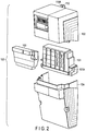
- FIG. 3 shows an appearance of the smart meter 100 and the concentrator 200.
- the smart meter 100 is provided on a first surface (for example, an upper surface 200A) of the concentrator 200. Power lines of three-wire system are connected to the smart meter 100.
- the smart meter 100 is fixed to the concentrator 200 by a screw 600 and other fixing members such that the central region of the concentrator 200 in the horizontal direction corresponds to the central region of the smart meter 100, and the upper end of the smart meter 100 is close to the upper end of the concentrator 200.
- a smart meter different in size from the smart meter 100 may be attached to the concentrator 200.
- the smart meter is fixed such that the central region of the concentrator 200 in the horizontal direction corresponds to the central region of the smart meter, and the upper end of the smart meter is close to the upper end of the concentrator 200.
- the concentrator 200 communicates with the data collection server 300 and the like through a base station by a communication of a cellular scheme.
- the concentrator 200 overlaps the smart meter 100 as shown in FIG. 3 , degradation in performance of an antenna provided in the concentrator 200 is expected because the smart meter 100 has a number of metal components such as a transformer.
- the metal terminal unit 101 also constitutes a major cause of the degradation in antenna performance.
- FIG. 4 shows a configuration of the concentrator 200.
- the concentrator 200 includes a housing 210.
- the housing 210 is formed of resin.
- the housing 210 includes a first sidewall 211 and a second sidewall 212 which are opposed in a direction orthogonal to the direction of arrangement of the smart meter 100 and the concentrator 200, for example, in the horizontal direction.
- the first sidewall 211 and the second sidewall 212 are connected to the first surface 200A.
- a power supply circuit board 221, a communication module (second communication module) 222, a wireless communication module 223, a first antenna 224, a second antenna 225, a control module 226 and the like are provided in the housing 210.
- the power supply circuit board 221 includes a circuit area 221A for generating electric power for driving the communication module 222, the wireless communication module 223 and the control module 226.
- the power supply circuit board 221 is provided on a side closer to the second sidewall 212 than the first sidewall 211 in the housing 210.
- the communication module 222 communicates with a smart meter provided in each electric power consuming spot.
- the communication module communicates with the smart meter by, for example, a power line communication (PLC) scheme or a wireless multi-hop scheme (Wi-SUN, ZigBee or the like).
- PLC power line communication
- Wi-SUN ZigBee
- an antenna (third antenna) 222B for the communication module 200 is further provided in the concentrator 200.
- the range of the wireless communication is narrower than that of the communication of the cellular scheme.
- the communication module 222 is provided on a communication board 222A.
- the antenna 222B is a monopole-type antenna using a ground layer 222D of the communication board 222A as a conductive plane of the antenna.
- the wireless communication module 223 communicates wirelessly with the data collection server 300.
- the wireless communication module 223 communicates wirelessly by the cellular scheme.
- the first antenna 224 and second antenna 225 are connected to the wireless communication module 223.
- the first antenna 224 is fixed in proximity to the first sidewall 211.
- the longitudinal direction of the first antenna 224 corresponds to a direction extending along the first sidewall 211.
- the second antenna 225 is fixed in proximity to the second sidewall 212.
- the second antenna 225 is provided closer to the second sidewall 212 than the circuit area 221A of the circuit board 221.
- the longitudinal direction of the second antenna 225 corresponds to a direction extending along the second sidewall 212.
- the first antenna 224 is provided closer to the first sidewall 211 than an electronic circuit area 227A of a control board 227 in which an electronic circuit including the wireless communication module 223, the control module 226 and the like is located. In other words, the first antenna 224 is provided between the first sidewall 211 and the electronic circuit area 227A.
- the control board 227 is provided on a side closer to the first sidewall 211 than the second sidewall 212 in the housing 210.
- the control board 227 and the communication board 222 are arranged in a direction orthogonal to a third sidewall 213 connected to the first sidewall 211 and the second sidewall 212. That is, the control board 227 and the communication board 222 are arranged in the vertical direction.
- the control board 227 and the power supply circuit board 221 are arranged in a direction orthogonal to the second sidewall 212. In other words, the control board 227 and the power supply circuit board 221 are arranged in the horizontal direction.
- the length in the direction parallel to the second sidewall of the power supply circuit board 221 is greater than that of each of the control board 227 and the communication module 222.
- the first antenna 224 and the control module 226 are mounted on the same board 227.
- a diversity antenna is constituted by the first antenna 224 and the second antenna 225.
- the first antenna 224 is a monopole-type antenna using a ground layer 227B of the board 227 as a conductive plane of the antenna.
- the second antenna 225 is a dipole-type antenna.
- the conductive plane is not necessarily provided on the board 227.
- a ground layer provided on a board other than the board 227 or a metal plate other than the board 227 may be used as the conductive plane.
- the first antenna 224 may be provided on a housing of the smart meter 200, not on the board 227. That is, the first antenna 224 may be provided, for example, on a sidewall surface of the first sidewall 211.
- the second antenna 225 is provided on the second sidewall 212 and is closer to the second sidewall 212 than the power supply circuit board 221. In other words, the second antenna 225 is provided between the second sidewall 212 and the power supply circuit board 221.
- the power supply circuit board 221 includes a board and various electronic components and electronic circuits provided on the board.
- the second antenna is provided closer to the second sidewall 212 than an electronic circuit area of the power supply circuit board 221. In other words, the second antenna 225 is provided between the second sidewall 212 and the electronic circuit area of the power supply circuit board 221.
- the second antenna 225 may be provided on the second sidewall 212.
- the second antenna 225 is provided outside the power supply circuit board 221 in FIG. 4 , but may be provided on the power supply circuit board 221.
- the wireless communication module 223 is equipped with two antenna ports 223 1 and 223 2 to which two feed lines are connected.
- the first antenna 224 is connected to the antenna port 223 1 through a feed line 224 FL .
- the second antenna 225 is connected to the antenna port 223 2 through a feed line 225 FL .
- the first antenna 224 extends downward at the time of installation (hereinafter referred to as downward) from a feed point 224 FP in a direction orthogonal to the horizontal direction (i.e., the vertical direction at the time of installation). In other words, the first antenna 224 extends from the feed point 224 FP parallel to the first sidewall 211 in the opposite direction of the communication module 222. The first antenna 224 may extend from the feed point 224 FP in the opposite direction of FIG. 4 on the board 227.
- An open end 224 1 of the first antenna 224 is directed downward in FIG. 4 , but may be directed upward on the plane of the drawing. In other words, the antenna 224 may be bent.
- the second antenna 225 extends from a feed point 225 FP in the direction orthogonal to the horizontal direction (i.e., the vertical direction at the time of installation). In other words, the second antenna 225 extends parallel to the second sidewall 212.
- One open end 225 1 of the second antenna 225 is directed upward and the other open end 225 2 of the second antenna 225 is directed downward at the time of installation in an installation position.
- an element of the second antenna 225 may be bent such that the open ends 225 1 and 225 2 of the second antenna 225 are directed to the same direction (upward or downward).
- the control module 226 acquires an amount of electric power consumption from a smart meter 100 in each installation spot by using the communication module 222.
- the control module 226 notifies the data collection server 300 of the acquired amounts of electric power consumption.
- the first antenna 224 is located in proximity to the first sidewall 211 and the second antenna 225 is located in proximity to the second sidewall 212, the first antenna 224 and the second antenna 225 are insulated from the influence of metal components provided in the smart meter 100. As a result, degradation in performance of the first antenna 224 and the second antenna 225 can be prevented.
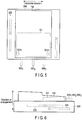
- FIG. 5 is a front view of the smart meter 100 and the concentrator 200.
- the antennas 224 and 225 are provided in positions that are deviated from the terminal unit 101 and the power lines.
- FIG. 6 is a side view of the smart meter 100 and the concentrator 200.
- the antennas 224 and 225 are provided in positions that are deviated from the terminal unit 101 and the power lines.
- the length in the horizontal direction of the housing 210 is greater than that of the smart meter 100 in FIG. 5 , but may be equal to that of the smart meter 100.
- screw holes provided on a lid of the housing of the concentrator 200 i.e., screw holes overlapping the screw holes 101A
- a screw hole 101A located near the first sidewall 211 is provided on the second sidewall 212 side with reference to the first antenna 224
- a screw hole 101A located near the second sidewall 212 is provided on the first sidewall 211 side with reference to the second antenna 225.
- the screw holes provided on the lid of the housing of the concentrator 200 are located near the first and second antennas.
- the first antenna 224 and the second antenna 225 should preferably be located so as not to overlap the smart meter 100 in the direction of arrangement of the smart meter 100 and the concentrator 200. However, high wireless performance can be maintained even if the first antenna 224 and the second antenna 225 overlap the smart meter 100 because these antennas are located near resin sidewalls.
- the monopole-type first antenna 224 and the dipole-type second antenna 225 are different in radiation pattern from each other, a correlation between the antennas can be reduced. As a result, the diversity effect can be improved.
- the concentrator may notify the data collection server 300 of electric power consumption data without using the communication of cellular scheme.
- each of the gas meters 400 1 , 400 2 , 400 3 , ... , 400 n measures an amount of gas consumption (step B11).
- Each of the gas meters 400 1 , 400 2 , 400 3 , ... , 400 n encrypts gas consumption data obtained by the measurement (step B12).
- Each of the gas meters 400 1 , 400 2 , 400 3 , ... , 400 n transmits the encrypted gas consumption data to the concentrator 200 by using the wireless communication device (step B13).
- the concentrator 200 transmits each of the gas meters 400 1 , 400 2 , 400 3 , ... , 400 n to the data collection server 300 (step B14).
- the data collection server 300 collects the gas consumption data (step B15).
- the data collection server 300 extracts gas consumption data from the collected data (including electric power consumption data) (step B16).
- the data collection server 300 transmits the extracted gas consumption data to the gas consumption management server 500, thereby supplying the gas consumption management server 500 with the gas consumption data in each installation spot (step B17).
- the gas consumption management server 500 acquires the gas consumption data by receiving the supplied amounts of gas consumption (step B18).
- FIG. 8 shows a modified example of the concentrator 200.
- the concentrator 200 does not include a dipole-type antenna.
- the power supply circuit board 221 is provided closer to a third sidewall 213 than a fourth sidewall 214.
- the third sidewall 213 and the fourth sidewall 214 are opposed to each other in the vertical direction.
- the third sidewall 213 is located on the lower side at the time of installation.
- the communication module 222 and the control board 227 are located closer to the fourth sidewall 214 than the third sidewall 213.
- the fourth sidewall 214 is located on the upper side at the time of installation.
- the communication module 222 and the control board 227 are aligned in the horizontal direction.
- the first antenna 224 is located in proximity to the first sidewall 211.
- the antenna 222B is located in proximity to the second sidewall 212.
- FIG. 9 shows a modified example of the concentrator 200.
- a layout of the power supply circuit board 221, the communication module 222 and the control board 227 is the same as that of the concentrator of FIG. 8 .
- the concentrator 200 includes a dipole-type second antenna 225.
- FIG. 10 shows a modified example of the concentrator 200. As shown in FIG. 10 , a dipole-type second antenna is not provided. A layout of the power supply circuit board 221, the communication module 222 and the control board 227 is the same as that of the concentrator of FIG. 4 . Since the first antenna 224 is located in proximity to the first sidewall 211 and the second antenna 222B is located in proximity to the first sidewall 211, the first antenna 224 and the second antenna 222B are insulated from the influence of metal components provided in the smart meter 100. Therefore, degradation in antenna performance can be prevented.
Landscapes
- Engineering & Computer Science (AREA)
- Computer Networks & Wireless Communication (AREA)
- Physics & Mathematics (AREA)
- General Physics & Mathematics (AREA)
- Signal Processing (AREA)
- Arrangements For Transmission Of Measured Signals (AREA)
- Radio Transmission System (AREA)
Claims (10)
- Konzentrator mit einer ersten Oberfläche, auf der eine Messvorrichtung (100) angeordnet sein kann, die so konfiguriert ist, dass sie einen Betrag des elektrischen Leistungsverbrauchs misst, wobei der Konzentrator umfasst:ein Gehäuse (210) mit einer ersten Seitenwand (211) und einer zweiten Seitenwand (212), die in einer Richtung senkrecht zu einer Anordnungsrichtung der Messvorrichtung und des Konzentrators gegenüberliegen, wobei die erste Seitenwand (211) und die zweite Seitenwand (212) mit der ersten Oberfläche verbunden sind;ein Kommunikationsmodul (222), das in dem Gehäuse (210) vorgesehen ist, zum Empfangen von Beträgen des elektrischen Leistungsverbrauchs von Messvorrichtungen (100) einschließlich der Messvorrichtung (100);ein drahtloses Kommunikationsmodul (223), das in dem Gehäuse (210) vorgesehen ist;ein Steuermodul (226), das so konfiguriert ist, dass es einen Datensammlungsserver (300) über die empfangenen Beträge des elektrischen Leistungsverbrauchs unter Verwendung des drahtlosen Kommunikationsmoduls (223) benachrichtigt;eine erste Antenne (224), die in der Nähe der ersten Seitenwand (211) vorgesehen ist, die auf einer Steuerplatine (227) vorgesehen ist, in der eine elektrische Schaltung, die das drahtlose Kommunikationsmodul (223) und das Steuermodul (226) umfasst, angeordnet ist, und die sich entlang der ersten Seitenwand (211) erstreckt, wobei die erste Antenne (224) mit dem drahtlosen Kommunikationsmodul (223) verbunden ist; undeine zweite Antenne (225), die in der Nähe der zweiten Seitenwand (212) vorgesehen ist, zwischen der zweiten Seitenwand (212) und einer Listungsversorgungsplatine (221) in dem Gehäuse (210) vorgesehen ist und sich entlang der zweiten Seitenwand (212) erstreckt, wobei die zweite Antenne (225) eine Form hat, die sich von einer Form der ersten Antenne (224) unterscheidet, und mit dem drahtlosen Kommunikationsmodul (223) verbunden ist.
- Der Konzentrator nach Anspruch 1, wobei die Steuerplatine (227) und die Stromversorgungsplatine (221) nebeneinander zwischen der ersten Seitenwand (211) und der zweiten Seitenwand (212) angeordnet sind.
- Der Konzentrator nach Anspruch 1, wobeidie erste Antenne (224) eine Monopolantenne ist,die zweite Antenne (225) eine Dipolantenne ist, unddie erste Antenne (224) und die zweite Antenne (225) eine Diversity-Antenne bilden.
- Der Konzentrator nach Anspruch 1, wobei das Kommunikationsmodul (222) auf einer Kommunikationsplatine (222A) im Gehäuse (210) vorgesehen ist, und
wobei die Steuerplatine (227) und die Kommunikationsplatine (222A) Seite an Seite in einer Richtung senkrecht zu einer dritten Seitenwand (213) angeordnet sind, die mit der ersten Seitenwand (211) und der zweiten Seitenwand (212) verbunden ist. - Der Konzentrator nach Anspruch 1, wobei
wenn das Kommunikationsmodul (222) ein drahtloses Kommunikationsmodul (223) ist, eine dritte Antenne (222B) auf der Kommunikationsplatine (222A) vorgesehen und so konfiguriert ist, dass sie die Beträge des Leistungsverbrauchs drahtlos empfängt. - Der Konzentrator nach Anspruch 5, wobei
die dritte Antenne (222B) in der Nähe der ersten Seitenwand (211) oder der zweiten Seitenwand (212) vorgesehen ist. - Der Konzentrator nach Anspruch 5, wobei
die dritte Antenne (222B) eine Monopolantenne ist, die eine Masseschicht der Kommunikationsplatine (222A) als leitende Ebene einer Antenne verwendet. - Der Konzentrator nach Anspruch 4, wobei
eine Länge einer ersten Seite der Leistungsversorgungsplatine (221) zwischen der ersten Seitenwand (211) und der zweiten Seitenwand (212) kürzer als eine Länge einer zweiten Seite der Leistungsversorgungsplatine (221) in einer Richtung senkrecht zu der ersten Seite ist, und die zweite Seite länger als die Kommunikationsplatine (222A) in der Länge in der Richtung senkrecht zu der ersten Seite ist. - Der Konzentrator nach Anspruch 1, wobei das Kommunikationsmodul (222) auf einer Kommunikationsplatine (222C) in dem Gehäuse vorgesehen ist, und
Wobei die Kommunikationsplatine (222C) und die Steuerplatine (117) Seite an Seite zwischen der ersten Seitenwand (211) und der zweiten Seitenwand (212) angeordnet sind. - Ein Datenerfassungsverfahren in einem Datenerfassungssystem, wobei das Datenerfassungssystem umfasst:einen Gaszähler (100) mit einer drahtlosen Kommunikationsvorrichtung (223);einen Konzentrator (200) mit einer ersten Oberfläche, auf der eine Messvorrichtung (100) angeordnet ist, die so konfiguriert ist, dass sie einen Betrag des elektrischen Leistungsverbrauchs misst, wobei der Konzentrator umfasst:ein Gehäuse (210) mit einer ersten Seitenwand (211) und einer zweiten Seitenwand (212), die in einer Richtung senkrecht zu einer Anordnungsrichtung der Messvorrichtung und des Konzentrators gegenüberliegen, wobei die erste Seitenwand (211) und die zweite Seitenwand (212) mit der ersten Oberfläche verbunden sind;ein Kommunikationsmodul (222), das in dem Gehäuse (210) vorgesehen ist, zum Empfangen von Beträgen des elektrischen Leistungsverbrauchs von Messvorrichtungen (100) einschließlich der Messvorrichtung (100);ein drahtloses Kommunikationsmodul (223), das in dem Gehäuse (210) vorgesehen ist;ein Steuermodul (226), das so konfiguriert ist, dass es einen Datensammlungsserver (300) über die empfangenen Beträge des elektrischen Leistungsverbrauchs unter Verwendung des drahtlosen Kommunikationsmoduls (223) benachrichtigt;eine erste Antenne (224), die in der Nähe der ersten Seitenwand (211) vorgesehen ist, die auf einer Steuerplatine (227) vorgesehen ist, in der eine elektrische Schaltung, die das drahtlose Kommunikationsmodul (223) und das Steuermodul (226) umfasst, angeordnet ist, und die sich entlang der ersten Seitenwand (211) erstreckt, wobei die erste Antenne (224) mit dem drahtlosen Kommunikationsmodul (223) verbunden ist; undeine zweite Antenne (225), die in der Nähe der zweiten Seitenwand (212) vorgesehen ist, zwischen der zweiten Seitenwand (212) und einer Leistungsversorgungsplatine (221) in dem Gehäuse (210) vorgesehen ist und sich entlang der zweiten Seitenwand (212) erstreckt, wobei die zweite Antenne (225) eine Form hat, die sich von einer Form der ersten Antenne (224) unterscheidet, und mit dem drahtlosen Kommunikationsmodul (223) verbunden ist;einen ersten Sammelserver, der elektrische Leistungsverbrauchsdaten und Gasverbrauchsdaten, die von dem Konzentrator übertragen werden, sammelt und die Gasverbrauchsdaten extrahiert; undeinen zweiten Sammelserver, der Daten von dem ersten Sammelserver empfängt, wobei das Datenerfassungsverfahren umfasst:Messen einer Gasverbrauchsmenge, Verschlüsseln der durch die Messung erhaltenen Gasverbrauchsdaten und Übertragen der verschlüsselten Gasverbrauchsdaten an den Konzentrator durch den Gaszähler; undErfassen der vom ersten Sammelserver extrahierten Gasverbrauchsdaten durch den zweiten Sammelserver.
Priority Applications (1)
| Application Number | Priority Date | Filing Date | Title |
|---|---|---|---|
| EP20190141.0A EP3771113B1 (de) | 2014-06-06 | 2014-06-06 | Konzentrator |
Applications Claiming Priority (1)
| Application Number | Priority Date | Filing Date | Title |
|---|---|---|---|
| PCT/JP2014/065118 WO2015186252A1 (ja) | 2014-06-06 | 2014-06-06 | コンセントレータ |
Related Child Applications (2)
| Application Number | Title | Priority Date | Filing Date |
|---|---|---|---|
| EP20190141.0A Division EP3771113B1 (de) | 2014-06-06 | 2014-06-06 | Konzentrator |
| EP20190141.0A Division-Into EP3771113B1 (de) | 2014-06-06 | 2014-06-06 | Konzentrator |
Publications (3)
| Publication Number | Publication Date |
|---|---|
| EP3154207A1 EP3154207A1 (de) | 2017-04-12 |
| EP3154207A4 EP3154207A4 (de) | 2018-01-31 |
| EP3154207B1 true EP3154207B1 (de) | 2020-09-16 |
Family
ID=54766345
Family Applications (2)
| Application Number | Title | Priority Date | Filing Date |
|---|---|---|---|
| EP20190141.0A Active EP3771113B1 (de) | 2014-06-06 | 2014-06-06 | Konzentrator |
| EP14893755.0A Active EP3154207B1 (de) | 2014-06-06 | 2014-06-06 | Konzentrator |
Family Applications Before (1)
| Application Number | Title | Priority Date | Filing Date |
|---|---|---|---|
| EP20190141.0A Active EP3771113B1 (de) | 2014-06-06 | 2014-06-06 | Konzentrator |
Country Status (4)
| Country | Link |
|---|---|
| US (1) | US9888299B2 (de) |
| EP (2) | EP3771113B1 (de) |
| JP (1) | JP6105164B2 (de) |
| WO (1) | WO2015186252A1 (de) |
Families Citing this family (2)
| Publication number | Priority date | Publication date | Assignee | Title |
|---|---|---|---|---|
| US11009922B2 (en) * | 2015-02-27 | 2021-05-18 | Electro Industries/Gaugetech | Wireless intelligent electronic device |
| US9897461B2 (en) | 2015-02-27 | 2018-02-20 | Electro Industries/Gauge Tech | Intelligent electronic device with expandable functionality |
Family Cites Families (22)
| Publication number | Priority date | Publication date | Assignee | Title |
|---|---|---|---|---|
| JP3519507B2 (ja) * | 1995-07-13 | 2004-04-19 | 松下電器産業株式会社 | 自動検針用無線装置 |
| JP3617218B2 (ja) | 1996-11-11 | 2005-02-02 | 松下電器産業株式会社 | 設備機器用アンテナ |
| US5986574A (en) * | 1997-10-16 | 1999-11-16 | Peco Energy Company | System and method for communication between remote locations |
| JP2002374112A (ja) | 2001-06-13 | 2002-12-26 | Matsushita Electric Ind Co Ltd | 情報通信装置用アンテナ |
| CA2703546A1 (en) * | 2007-10-25 | 2009-04-30 | Trilliant Networks, Inc. | Gas meter having ultra-sensitive magnetic material retrofitted onto meter dial and method for performing meter retrofit |
| JP2009253788A (ja) | 2008-04-09 | 2009-10-29 | Ricoh Elemex Corp | 無線通信ユニット及びそれを備えた流量計 |
| WO2010118171A1 (en) * | 2009-04-07 | 2010-10-14 | Rf Savvy Llc | Smart meter cover with integral, untethered antenna elements for ami communications |
| JP2011081518A (ja) * | 2009-10-05 | 2011-04-21 | Panasonic Electric Works Co Ltd | 遠隔検針装置 |
| WO2012042748A1 (ja) | 2010-09-30 | 2012-04-05 | パナソニック株式会社 | 無線通信機 |
| JP5711601B2 (ja) * | 2011-04-28 | 2015-05-07 | 株式会社東芝 | 使用量測定システム |
| JP2013021516A (ja) * | 2011-07-11 | 2013-01-31 | Toshiba Corp | 使用量測定システム、無線通信用センタ装置および使用量測定システム用プログラム |
| JP5701715B2 (ja) * | 2011-08-12 | 2015-04-15 | 株式会社東芝 | エネルギー管理装置、電力管理システムおよびプログラム |
| JP2013106335A (ja) * | 2011-11-17 | 2013-05-30 | Panasonic Corp | 無線装置 |
| US20140343744A1 (en) * | 2013-03-14 | 2014-11-20 | The Powerwise Group Inc. | Autonomous smart grid demand measurement system and method |
| FR3005228B1 (fr) * | 2013-04-30 | 2016-11-25 | Electricite De France | Interface de communication entre un equipement et un systeme de comptage de fluide |
| DK3072308T3 (en) * | 2013-11-22 | 2018-04-23 | Kamstrup As | CONSUMER FAULT WITH ERROR CORRECTION |
| WO2015136893A1 (ja) * | 2014-03-11 | 2015-09-17 | 日本電気株式会社 | メータリング装置、及び通信制御方法 |
| JP5976028B2 (ja) * | 2014-03-27 | 2016-08-23 | 京セラドキュメントソリューションズ株式会社 | 電子機器 |
| US10243364B2 (en) * | 2014-05-19 | 2019-03-26 | Nec Corporation | Control device, control method, and program |
| US9612133B2 (en) * | 2014-07-14 | 2017-04-04 | International Technological University | Smart meter system communication methods |
| TWI579791B (zh) * | 2015-11-30 | 2017-04-21 | 財團法人資訊工業策進會 | 智慧型電表系統 |
| CN205862557U (zh) * | 2016-01-18 | 2017-01-04 | 国网山东省电力公司巨野县供电公司 | 一种电能表集中抄表装置 |
-
2014
- 2014-06-06 EP EP20190141.0A patent/EP3771113B1/de active Active
- 2014-06-06 WO PCT/JP2014/065118 patent/WO2015186252A1/ja not_active Ceased
- 2014-06-06 JP JP2016525655A patent/JP6105164B2/ja active Active
- 2014-06-06 EP EP14893755.0A patent/EP3154207B1/de active Active
-
2016
- 2016-12-05 US US15/369,451 patent/US9888299B2/en active Active
Non-Patent Citations (1)
| Title |
|---|
| None * |
Also Published As
| Publication number | Publication date |
|---|---|
| JP6105164B2 (ja) | 2017-03-29 |
| US20170085969A1 (en) | 2017-03-23 |
| EP3771113A1 (de) | 2021-01-27 |
| US9888299B2 (en) | 2018-02-06 |
| EP3771113B1 (de) | 2022-07-27 |
| EP3154207A1 (de) | 2017-04-12 |
| WO2015186252A1 (ja) | 2015-12-10 |
| EP3154207A4 (de) | 2018-01-31 |
| JPWO2015186252A1 (ja) | 2017-04-20 |
Similar Documents
| Publication | Publication Date | Title |
|---|---|---|
| MX2014007272A (es) | Etiqueta de identificacion de radiofrecuencia. | |
| US20210098906A1 (en) | Sensor device for an electrical terminal arrangement, electrical terminal arrangement, electrical terminal block, switchgear cabinet and read-out device | |
| EP2876821B1 (de) | Drahtlose vorrichtung | |
| EP3154207B1 (de) | Konzentrator | |
| CN103579781A (zh) | 具有相同主波束辐射特性的双极化天线系统 | |
| JP2015129647A (ja) | 遠隔検針装置 | |
| CN111712896A (zh) | 用于开关设备的无线感测系统和方法 | |
| US10719053B2 (en) | Wearable device | |
| CN106656286A (zh) | 在无线功能网络中基于mimo传输技术的能量传输系统 | |
| EP2863474A1 (de) | Drahtlose vorrichtung | |
| CN104539378B (zh) | 具有自检功能的天线系统 | |
| CN105633546B (zh) | 天线结构及具有该天线结构的无线通信装置 | |
| US20140240194A1 (en) | Small-cell antenna arrangement | |
| CN101322036A (zh) | 能量计仪表的远程读取的方法和装置 | |
| US9685988B2 (en) | Enhancement device for a wireless antenna | |
| MX2016009509A (es) | Sistema de monitoreo remoto de nivel de contenido de gas en tanques estacionarios. | |
| CN208423133U (zh) | 一种多标识识别天线装置 | |
| KR20130045031A (ko) | 금속 배터리 커버를 가지는 단말기의 안테나 | |
| RU82338U1 (ru) | Счетчик электрической энергии | |
| CN106295446A (zh) | 具有精确定位功能的多天线激活源 | |
| CN112424997B (zh) | 井盖和安装天线组件的方法 | |
| US11456536B2 (en) | Resonant loop or antenna for wireless power transfer and secure communication | |
| Rezer et al. | Wireless sensor system for electrical cabinet monitoring | |
| WO2026025138A1 (en) | Water meter system | |
| KR101188780B1 (ko) | 송배전선로 감시진단장치의 안테나 |
Legal Events
| Date | Code | Title | Description |
|---|---|---|---|
| STAA | Information on the status of an ep patent application or granted ep patent |
Free format text: STATUS: THE INTERNATIONAL PUBLICATION HAS BEEN MADE |
|
| PUAI | Public reference made under article 153(3) epc to a published international application that has entered the european phase |
Free format text: ORIGINAL CODE: 0009012 |
|
| STAA | Information on the status of an ep patent application or granted ep patent |
Free format text: STATUS: REQUEST FOR EXAMINATION WAS MADE |
|
| 17P | Request for examination filed |
Effective date: 20161201 |
|
| AK | Designated contracting states |
Kind code of ref document: A1 Designated state(s): AL AT BE BG CH CY CZ DE DK EE ES FI FR GB GR HR HU IE IS IT LI LT LU LV MC MK MT NL NO PL PT RO RS SE SI SK SM TR |
|
| AX | Request for extension of the european patent |
Extension state: BA ME |
|
| DAX | Request for extension of the european patent (deleted) | ||
| A4 | Supplementary search report drawn up and despatched |
Effective date: 20180105 |
|
| RIC1 | Information provided on ipc code assigned before grant |
Ipc: G08C 17/00 20060101ALI20171222BHEP Ipc: H01Q 1/42 20060101ALI20171222BHEP Ipc: H04Q 9/00 20060101ALI20171222BHEP Ipc: H04B 7/02 20180101AFI20171222BHEP Ipc: G08C 15/00 20060101ALI20171222BHEP |
|
| STAA | Information on the status of an ep patent application or granted ep patent |
Free format text: STATUS: EXAMINATION IS IN PROGRESS |
|
| 17Q | First examination report despatched |
Effective date: 20190719 |
|
| GRAP | Despatch of communication of intention to grant a patent |
Free format text: ORIGINAL CODE: EPIDOSNIGR1 |
|
| STAA | Information on the status of an ep patent application or granted ep patent |
Free format text: STATUS: GRANT OF PATENT IS INTENDED |
|
| INTG | Intention to grant announced |
Effective date: 20200408 |
|
| GRAS | Grant fee paid |
Free format text: ORIGINAL CODE: EPIDOSNIGR3 |
|
| GRAA | (expected) grant |
Free format text: ORIGINAL CODE: 0009210 |
|
| STAA | Information on the status of an ep patent application or granted ep patent |
Free format text: STATUS: THE PATENT HAS BEEN GRANTED |
|
| AK | Designated contracting states |
Kind code of ref document: B1 Designated state(s): AL AT BE BG CH CY CZ DE DK EE ES FI FR GB GR HR HU IE IS IT LI LT LU LV MC MK MT NL NO PL PT RO RS SE SI SK SM TR |
|
| REG | Reference to a national code |
Ref country code: GB Ref legal event code: FG4D |
|
| REG | Reference to a national code |
Ref country code: CH Ref legal event code: EP |
|
| REG | Reference to a national code |
Ref country code: DE Ref legal event code: R096 Ref document number: 602014070356 Country of ref document: DE |
|
| REG | Reference to a national code |
Ref country code: IE Ref legal event code: FG4D |
|
| REG | Reference to a national code |
Ref country code: AT Ref legal event code: REF Ref document number: 1315085 Country of ref document: AT Kind code of ref document: T Effective date: 20201015 |
|
| PG25 | Lapsed in a contracting state [announced via postgrant information from national office to epo] |
Ref country code: BG Free format text: LAPSE BECAUSE OF FAILURE TO SUBMIT A TRANSLATION OF THE DESCRIPTION OR TO PAY THE FEE WITHIN THE PRESCRIBED TIME-LIMIT Effective date: 20201216 Ref country code: SE Free format text: LAPSE BECAUSE OF FAILURE TO SUBMIT A TRANSLATION OF THE DESCRIPTION OR TO PAY THE FEE WITHIN THE PRESCRIBED TIME-LIMIT Effective date: 20200916 Ref country code: NO Free format text: LAPSE BECAUSE OF FAILURE TO SUBMIT A TRANSLATION OF THE DESCRIPTION OR TO PAY THE FEE WITHIN THE PRESCRIBED TIME-LIMIT Effective date: 20201216 Ref country code: GR Free format text: LAPSE BECAUSE OF FAILURE TO SUBMIT A TRANSLATION OF THE DESCRIPTION OR TO PAY THE FEE WITHIN THE PRESCRIBED TIME-LIMIT Effective date: 20201217 Ref country code: HR Free format text: LAPSE BECAUSE OF FAILURE TO SUBMIT A TRANSLATION OF THE DESCRIPTION OR TO PAY THE FEE WITHIN THE PRESCRIBED TIME-LIMIT Effective date: 20200916 Ref country code: FI Free format text: LAPSE BECAUSE OF FAILURE TO SUBMIT A TRANSLATION OF THE DESCRIPTION OR TO PAY THE FEE WITHIN THE PRESCRIBED TIME-LIMIT Effective date: 20200916 |
|
| REG | Reference to a national code |
Ref country code: AT Ref legal event code: MK05 Ref document number: 1315085 Country of ref document: AT Kind code of ref document: T Effective date: 20200916 |
|
| REG | Reference to a national code |
Ref country code: NL Ref legal event code: MP Effective date: 20200916 |
|
| PG25 | Lapsed in a contracting state [announced via postgrant information from national office to epo] |
Ref country code: RS Free format text: LAPSE BECAUSE OF FAILURE TO SUBMIT A TRANSLATION OF THE DESCRIPTION OR TO PAY THE FEE WITHIN THE PRESCRIBED TIME-LIMIT Effective date: 20200916 Ref country code: LV Free format text: LAPSE BECAUSE OF FAILURE TO SUBMIT A TRANSLATION OF THE DESCRIPTION OR TO PAY THE FEE WITHIN THE PRESCRIBED TIME-LIMIT Effective date: 20200916 |
|
| REG | Reference to a national code |
Ref country code: LT Ref legal event code: MG4D |
|
| PG25 | Lapsed in a contracting state [announced via postgrant information from national office to epo] |
Ref country code: CZ Free format text: LAPSE BECAUSE OF FAILURE TO SUBMIT A TRANSLATION OF THE DESCRIPTION OR TO PAY THE FEE WITHIN THE PRESCRIBED TIME-LIMIT Effective date: 20200916 Ref country code: PT Free format text: LAPSE BECAUSE OF FAILURE TO SUBMIT A TRANSLATION OF THE DESCRIPTION OR TO PAY THE FEE WITHIN THE PRESCRIBED TIME-LIMIT Effective date: 20210118 Ref country code: LT Free format text: LAPSE BECAUSE OF FAILURE TO SUBMIT A TRANSLATION OF THE DESCRIPTION OR TO PAY THE FEE WITHIN THE PRESCRIBED TIME-LIMIT Effective date: 20200916 Ref country code: NL Free format text: LAPSE BECAUSE OF FAILURE TO SUBMIT A TRANSLATION OF THE DESCRIPTION OR TO PAY THE FEE WITHIN THE PRESCRIBED TIME-LIMIT Effective date: 20200916 Ref country code: EE Free format text: LAPSE BECAUSE OF FAILURE TO SUBMIT A TRANSLATION OF THE DESCRIPTION OR TO PAY THE FEE WITHIN THE PRESCRIBED TIME-LIMIT Effective date: 20200916 Ref country code: RO Free format text: LAPSE BECAUSE OF FAILURE TO SUBMIT A TRANSLATION OF THE DESCRIPTION OR TO PAY THE FEE WITHIN THE PRESCRIBED TIME-LIMIT Effective date: 20200916 Ref country code: SM Free format text: LAPSE BECAUSE OF FAILURE TO SUBMIT A TRANSLATION OF THE DESCRIPTION OR TO PAY THE FEE WITHIN THE PRESCRIBED TIME-LIMIT Effective date: 20200916 |
|
| PG25 | Lapsed in a contracting state [announced via postgrant information from national office to epo] |
Ref country code: ES Free format text: LAPSE BECAUSE OF FAILURE TO SUBMIT A TRANSLATION OF THE DESCRIPTION OR TO PAY THE FEE WITHIN THE PRESCRIBED TIME-LIMIT Effective date: 20200916 Ref country code: AT Free format text: LAPSE BECAUSE OF FAILURE TO SUBMIT A TRANSLATION OF THE DESCRIPTION OR TO PAY THE FEE WITHIN THE PRESCRIBED TIME-LIMIT Effective date: 20200916 Ref country code: AL Free format text: LAPSE BECAUSE OF FAILURE TO SUBMIT A TRANSLATION OF THE DESCRIPTION OR TO PAY THE FEE WITHIN THE PRESCRIBED TIME-LIMIT Effective date: 20200916 Ref country code: PL Free format text: LAPSE BECAUSE OF FAILURE TO SUBMIT A TRANSLATION OF THE DESCRIPTION OR TO PAY THE FEE WITHIN THE PRESCRIBED TIME-LIMIT Effective date: 20200916 Ref country code: IS Free format text: LAPSE BECAUSE OF FAILURE TO SUBMIT A TRANSLATION OF THE DESCRIPTION OR TO PAY THE FEE WITHIN THE PRESCRIBED TIME-LIMIT Effective date: 20210116 |
|
| REG | Reference to a national code |
Ref country code: DE Ref legal event code: R097 Ref document number: 602014070356 Country of ref document: DE |
|
| PG25 | Lapsed in a contracting state [announced via postgrant information from national office to epo] |
Ref country code: SK Free format text: LAPSE BECAUSE OF FAILURE TO SUBMIT A TRANSLATION OF THE DESCRIPTION OR TO PAY THE FEE WITHIN THE PRESCRIBED TIME-LIMIT Effective date: 20200916 |
|
| PLBE | No opposition filed within time limit |
Free format text: ORIGINAL CODE: 0009261 |
|
| STAA | Information on the status of an ep patent application or granted ep patent |
Free format text: STATUS: NO OPPOSITION FILED WITHIN TIME LIMIT |
|
| 26N | No opposition filed |
Effective date: 20210617 |
|
| PG25 | Lapsed in a contracting state [announced via postgrant information from national office to epo] |
Ref country code: DK Free format text: LAPSE BECAUSE OF FAILURE TO SUBMIT A TRANSLATION OF THE DESCRIPTION OR TO PAY THE FEE WITHIN THE PRESCRIBED TIME-LIMIT Effective date: 20200916 Ref country code: SI Free format text: LAPSE BECAUSE OF FAILURE TO SUBMIT A TRANSLATION OF THE DESCRIPTION OR TO PAY THE FEE WITHIN THE PRESCRIBED TIME-LIMIT Effective date: 20200916 |
|
| PG25 | Lapsed in a contracting state [announced via postgrant information from national office to epo] |
Ref country code: IT Free format text: LAPSE BECAUSE OF FAILURE TO SUBMIT A TRANSLATION OF THE DESCRIPTION OR TO PAY THE FEE WITHIN THE PRESCRIBED TIME-LIMIT Effective date: 20200916 |
|
| PG25 | Lapsed in a contracting state [announced via postgrant information from national office to epo] |
Ref country code: MC Free format text: LAPSE BECAUSE OF FAILURE TO SUBMIT A TRANSLATION OF THE DESCRIPTION OR TO PAY THE FEE WITHIN THE PRESCRIBED TIME-LIMIT Effective date: 20200916 |
|
| REG | Reference to a national code |
Ref country code: CH Ref legal event code: PL |
|
| REG | Reference to a national code |
Ref country code: BE Ref legal event code: MM Effective date: 20210630 |
|
| PG25 | Lapsed in a contracting state [announced via postgrant information from national office to epo] |
Ref country code: LU Free format text: LAPSE BECAUSE OF NON-PAYMENT OF DUE FEES Effective date: 20210606 |
|
| PG25 | Lapsed in a contracting state [announced via postgrant information from national office to epo] |
Ref country code: LI Free format text: LAPSE BECAUSE OF NON-PAYMENT OF DUE FEES Effective date: 20210630 Ref country code: IE Free format text: LAPSE BECAUSE OF NON-PAYMENT OF DUE FEES Effective date: 20210606 Ref country code: CH Free format text: LAPSE BECAUSE OF NON-PAYMENT OF DUE FEES Effective date: 20210630 |
|
| PG25 | Lapsed in a contracting state [announced via postgrant information from national office to epo] |
Ref country code: BE Free format text: LAPSE BECAUSE OF NON-PAYMENT OF DUE FEES Effective date: 20210630 |
|
| REG | Reference to a national code |
Ref country code: FR Ref legal event code: PLFP Year of fee payment: 10 |
|
| PG25 | Lapsed in a contracting state [announced via postgrant information from national office to epo] |
Ref country code: HU Free format text: LAPSE BECAUSE OF FAILURE TO SUBMIT A TRANSLATION OF THE DESCRIPTION OR TO PAY THE FEE WITHIN THE PRESCRIBED TIME-LIMIT; INVALID AB INITIO Effective date: 20140606 |
|
| PG25 | Lapsed in a contracting state [announced via postgrant information from national office to epo] |
Ref country code: CY Free format text: LAPSE BECAUSE OF FAILURE TO SUBMIT A TRANSLATION OF THE DESCRIPTION OR TO PAY THE FEE WITHIN THE PRESCRIBED TIME-LIMIT Effective date: 20200916 |
|
| PG25 | Lapsed in a contracting state [announced via postgrant information from national office to epo] |
Ref country code: MK Free format text: LAPSE BECAUSE OF FAILURE TO SUBMIT A TRANSLATION OF THE DESCRIPTION OR TO PAY THE FEE WITHIN THE PRESCRIBED TIME-LIMIT Effective date: 20200916 |
|
| PG25 | Lapsed in a contracting state [announced via postgrant information from national office to epo] |
Ref country code: TR Free format text: LAPSE BECAUSE OF FAILURE TO SUBMIT A TRANSLATION OF THE DESCRIPTION OR TO PAY THE FEE WITHIN THE PRESCRIBED TIME-LIMIT Effective date: 20200916 |
|
| PG25 | Lapsed in a contracting state [announced via postgrant information from national office to epo] |
Ref country code: MT Free format text: LAPSE BECAUSE OF FAILURE TO SUBMIT A TRANSLATION OF THE DESCRIPTION OR TO PAY THE FEE WITHIN THE PRESCRIBED TIME-LIMIT Effective date: 20200916 |
|
| PGFP | Annual fee paid to national office [announced via postgrant information from national office to epo] |
Ref country code: DE Payment date: 20250402 Year of fee payment: 12 |
|
| PGFP | Annual fee paid to national office [announced via postgrant information from national office to epo] |
Ref country code: GB Payment date: 20250401 Year of fee payment: 12 |
|
| PGFP | Annual fee paid to national office [announced via postgrant information from national office to epo] |
Ref country code: FR Payment date: 20250401 Year of fee payment: 12 |