EP3155151B1 - Buse de filage pour un métier à filer à jet d'air et métier à filer à jet d'air avec buse de filage correspondante - Google Patents
Buse de filage pour un métier à filer à jet d'air et métier à filer à jet d'air avec buse de filage correspondante Download PDFInfo
- Publication number
- EP3155151B1 EP3155151B1 EP15731667.0A EP15731667A EP3155151B1 EP 3155151 B1 EP3155151 B1 EP 3155151B1 EP 15731667 A EP15731667 A EP 15731667A EP 3155151 B1 EP3155151 B1 EP 3155151B1
- Authority
- EP
- European Patent Office
- Prior art keywords
- spinning
- air
- piecing
- spinning nozzle
- inlet opening
- Prior art date
- Legal status (The legal status is an assumption and is not a legal conclusion. Google has not performed a legal analysis and makes no representation as to the accuracy of the status listed.)
- Active
Links
Images


Classifications
-
- D—TEXTILES; PAPER
- D01—NATURAL OR MAN-MADE THREADS OR FIBRES; SPINNING
- D01H—SPINNING OR TWISTING
- D01H7/00—Spinning or twisting arrangements
- D01H7/92—Spinning or twisting arrangements for imparting transient twist, i.e. false twist
-
- D—TEXTILES; PAPER
- D01—NATURAL OR MAN-MADE THREADS OR FIBRES; SPINNING
- D01H—SPINNING OR TWISTING
- D01H4/00—Open-end spinning machines or arrangements for imparting twist to independently moving fibres separated from slivers; Piecing arrangements therefor; Covering endless core threads with fibres by open-end spinning techniques
- D01H4/02—Open-end spinning machines or arrangements for imparting twist to independently moving fibres separated from slivers; Piecing arrangements therefor; Covering endless core threads with fibres by open-end spinning techniques imparting twist by a fluid, e.g. air vortex
-
- D—TEXTILES; PAPER
- D01—NATURAL OR MAN-MADE THREADS OR FIBRES; SPINNING
- D01H—SPINNING OR TWISTING
- D01H1/00—Spinning or twisting machines in which the product is wound-up continuously
- D01H1/11—Spinning by false-twisting
- D01H1/115—Spinning by false-twisting using pneumatic means
Definitions
- the present invention relates to a spinneret for an air spinning machine, which serves for the production of roving from a fiber structure, wherein the spinneret has an inlet opening for the entry of a fiber composite, wherein the spinneret has a vortex chamber of an at least partially limited vortex chamber, the inlet opening in a arranged in the installed state of the spinneret predetermined transport direction of the fiber assembly, wherein the spinneret has a spaced from the inlet opening in the transport direction opening through which a hollow spindle is inserted into the vortex chamber, wherein the spinneret has at least one spin air duct, via the air into the interior Whirl chamber can be introduced, wherein the spinning air duct extends between a spinning air inlet opening and a spinning air outlet opening and the spinning air inlet opening in the region of an outer side of the spinneret and the spinning air outlet
- the spinneret has at least one Anspinn Kunststoffkanal via which also air into the interior of the vortex chamber can
- Roving is produced with the aid of roving machines, usually with the aid of stretch-pretreated (eg doubled) slivers, and serves as a template for the subsequent spinning process in which the individual fibers of the roving are spun into a fiber yarn, for example by means of a ring spinning machine ,
- stretch-pretreated eg doubled
- slivers serves as a template for the subsequent spinning process in which the individual fibers of the roving are spun into a fiber yarn, for example by means of a ring spinning machine
- Said strength is important to prevent ripping of the roving during winding on a spool or during the supply to the downstream spinning machine.
- the protective rotation granted may only be so strong that a cohesion of the individual fibers is ensured during the individual winding and unwinding operations as well as corresponding transport processes between the respective machine types.
- the protective rotation it must be ensured that the roving can be further processed in a spinning machine - the roving must therefore continue to be delayable.
- flyers In order to produce a corresponding roving, so-called flyers are primarily used, but their delivery speed is limited due to centrifugal forces occurring. Therefore, there were already many suggestions to bypass the flyer or to replace it with an alternative machine type (see for example EP 0 375 242 A2 . DE 32 37 989 C2 ).
- the vortex air flow at this initial stage usually has a different characteristic than during regular spinning operation in which the vortex chamber is already passed by a continuous fiber strand (the fiber strand is made up of the fiber structure in the region of the inlet opening of the spinneret and within the vortex chamber the roving produced by the fiber structure and the vortex chamber leaving a vortex channel together).
- the object of the present invention is to propose a spinneret and an air-spinning machine equipped therewith for the production of roving in which the individual flow sections for the spinning and piecing air are advantageously positioned and aligned.
- JP S61 119725 discloses a pneumatically operated nozzle.
- DE102007006674 discloses an air-spinning device for producing a thread by means of a circulating air flow.
- DE 102 51 727 A1 DE10351727 discloses a method and apparatus for making a flyer.
- WO 2013/003962 A1 discloses a roving machine for producing a roving according to the preamble of claim 1.
- the spinneret is characterized in that the at least one piecing air channel extends at least partially opposite to the transport direction, starting from its piecing air inlet opening, wherein the spinneret is the part of a corresponding air spinning machine which surrounds or forms the vortex chamber and the spinning air nozzles and Anspinn Kunststoffdüsen at least partially comprises (wherein the spinneret itself may be formed one or more parts).
- the solution according to the invention has the advantage that the Anspinn Kunststoff inlet openings (over which the Anspinn Kunststoff enters the Anspinn Kunststoffkanal) seen in the transport direction after the spinning air inlet openings (on the the spinning air enters the spin air duct) can be placed.
- the Anspinn Kunststoff outlet openings (over which the Anspinn Kunststoff enters the vortex chamber) can thus be placed in the transport direction approximately at the height of the spinning air outlet openings, yet both air channels (spinning air duct and Anspinn Kunststoffkanal) can be supplied by different sources of compressed air.
- the Anspinnluftkanal comprises a first channel section, which extends from the Anspinn Kunststoff inlet opening within the Wirbelhuntwandung at least partially opposite to the transport direction, wherein the Anspinn Kunststoffkanal beyond a second channel section includes, extending from the first channel portion in the direction of Anspinn Kunststoff-outlet opening.
- the Anspinn Kunststoff entry in this case is not continuous straight. Rather, the course of Anspinn Kunststoffkanals (which generally extends between the Anspinnluft inlet opening placed in the region of the outside and the Anspinn Kunststoff-outlet opening into the swirl chamber) within the Wirbelbibdung changes at least once.
- the first channel section starting from the piecing air inlet opening, runs counter to the transport direction and parallel to a central axis of the spinneret. Within the vortex chamber wall, he finally goes over, for example via a kink, in the second channel section, which in turn extends in the direction of the vortex chamber.
- the first channel section (in a side view of the spinneret) encloses an angle with a central axis of the spinneret whose magnitude is 0 ° to 30 °, preferably 0 ° to 15 °, particularly preferably 0 ° to 10 °, is. While an angle of 0 ° means that the first channel section is parallel to the central axis of the spinneret, an angle greater than 0 ° results in the first channel section being inclined with respect to the central axis.
- first channel section and / or the second channel section have a rectilinear central axis.
- the respective channel section can be made through a corresponding bore which is introduced into the vortex chamber wall.
- impairments of the respective air currents are avoided.
- the diameters of the respective channel sections are preferably the same size or deviate from each other by only a maximum of 20%.
- first channel section and / or the second channel section is formed by a bore introduced from the outside of the spinneret into the spinneret.
- a bore can be easily and especially, with respect to its orientation, very precisely introduced.
- first channel section and the second channel section through a from the outside of the spinneret in the spinneret introduced bore is formed, wherein the respective holes intersect within the Wirbelfflewandung.
- the intersection of both holes represents in this case the transition from the first to the second channel section.
- the said holes are closed at least on one side in the region of the outside of the spinneret by an airtight seal.
- the Anspinn Kunststoffkanal can be formed by a plurality of bores, each extending from the outside into the vortex chamber, wherein at least one of the holes can completely penetrate the Wirbelhuntwandung, starting from the outside of the spinneret.
- the first channel section is in this case formed by a first bore extending from an end face of the spinneret and extending in the transport direction, wherein the bore is subsequently sealed in the region of the end face by means of a seal (which is preferably glued in).
- the second channel portion is in this case vorzgugator formed by a second bore which extends from an extending between the two end faces of the spinneret outside to the vortex chamber, both holes intersect within the Wirbelhuntwandung and sealed the second bore in the outer side is.
- the second channel section branches off from the first channel section between a seal of the first channel section and the piecing air inlet opening.
- the two channel sections intersect in this case within the Wirbelzigdung, wherein the first channel section on the one hand via its Anspinn Kunststoff inlet opening can be supplied and is hermetically sealed on the other side by a seal.
- the second channel section extends from the piecing air outlet opening into the first channel section.
- the second channel section branches off at an angle ⁇ from the first channel section, wherein the amount of said angle is 40 ° to 80 °, preferably 45 ° to 75 °, particularly preferably 50 ° to 70 °.
- Such an angle causes an air flow, which does not have to be redirected again before entering the vortex chamber and thus promises a successful piecing without further intervention.
- the spinning-air outlet opening and the piecing-air outlet opening are arranged in a common plane extending perpendicular to the transport direction or less than 3 mm, preferably less than 2 mm, particularly preferably less than 1 mm, viewed from one another in the transport direction are spaced. Nevertheless, the spin air duct and Anspinn Kunststoffkanal of separate Compressed air supplies are supplied, since the spinning air inlet opening and Anspinn Kunststoffeintrittsö réelle seen in the transport direction are spaced from each other.
- the piecing air inlet opening and the piecing air outlet opening seen in the transport direction at least 4 mm, preferably at least 8 mm, more preferably at least 12 mm, and / or less than 30 mm, preferably less than 25 mm, especially preferably less than 20 mm, are spaced from each other.
- the said areas ensure that sufficient space is available between the respective inlet openings in order to be able to supply them with compressed air via separate compressed-air supplies without the spinneret having to assume such large dimensions here that it would be unsuitable for installation in an air-spinning machine.
- the air-jet spinning machine according to the invention for the production of roving is finally distinguished by the fact that it comprises at least one spinning station with a spinneret, wherein the spinning station is formed, one of the spinneret in a transport direction supplied fiber strand within a partially limited by the spinneret vortex chamber by means of an air flow Rotation, and wherein the spinneret has the features according to the invention the previous or subsequent description.
- the features can be realized individually or in any combination, as long as it does not lead to contradictions.
- the spinneret has a plurality of spinning air ducts and a plurality of Anspinn Kunststoffkanäle spaced apart in the transport direction, wherein the spinning air inlet openings of the spinning air ducts and Anspinn Kunststoff inlet openings of Anspinn Kunststoffkanäle by sealing elements, preferably in the form of sealing rings, are separated.
- the spinning-air inlet openings and the piecing-air inlet openings are preferably arranged in the region of the outside of the spinneret, in particular on a surface section of the same between the end faces of the spinneret.
- the sealing elements are placed in the region of an outer side of the spinneret and preferably enclose them circumferentially.
- the sealing elements are designed as annular sealing rubbers, wherein it is particularly advantageous if in each case a sealing element (seen in the transport direction) between the inlet opening of the spinneret and the spinning air inlet openings, between the spinning air inlet openings and the piecing air inlet openings and between the piecing air inlet openings and the opening of the spinneret over which the roving leaves the spinneret are arranged.
- the spinning station has a spinneret-receiving carrier element, wherein the carrier element has a spinning air inlet openings adjacent and in fluid communication therewith spinning air chamber, and wherein the carrier element adjacent to Anspinn Kunststoff inlet openings and in fluid communication Anspinn Kunststoffwait having.
- the carrier element may, for example, have a bore into which the spinneret is inserted (the attachment of the spinneret in the carrier may, for example, be realized by means of screws).
- the air chamber and the piecing air chamber are airtight separated from each other by means of the sealing elements mentioned in the previous section.
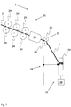
- FIG. 1 shows a schematic view of a section of an air-jet spinning machine according to the invention, which serves to produce roving 1.
- the air-spinning machine can comprise a drafting system 25 with a plurality of corresponding drafting rollers 24, which are supplied with a fiber structure 2, for example in the form of a relined conveyor belt.
- the air spinning machine shown in principle comprises a spaced apart from the drafting 25 yarn-forming unit 33 with an internal and shown in the following figures spinneret 3 and a in FIG. 2 shown Garn Strukturselement 8 in the form of a hollow spindle, wherein the spinneret 3 at least partially limits a vortex chamber 6.
- the fiber structure 2 or at least a part of the fibers of the fiber composite 2 is provided with a protective rotation.
- the air-spinning machine may include a take-off unit 27 with preferably two take-off rollers 26 for the roving 1 (the take-off unit 27 is not absolutely necessary).
- the trigger unit 27 or the yarn-forming unit 33 downstream winding device 31 is present, which in turn should include at least one sleeve drive 30 and one associated with the sleeve drive 30 and in principle known (but not shown) sleeve receptacle, with the aid of which a sleeve 29 can be fixed and set into rotary motion via the sleeve drive 30 in order to be able to wind the roving 1, preferably supported by a traversing unit 28, onto the sleeve 29.
- the air-jet spinning machine works according to a special air-spinning process.
- the fiber structure 2 is guided in a transport direction T via an inlet opening 4 shown in the following figures into the swirl chamber 6 of the spinneret 3 of the yarn-forming unit (wherein the spinneret 3 embodied according to the invention is inserted into the FIGS. 3 to 8 is shown in more detail).
- a protective rotation ie at least part of the fibers of the fiber composite 2 is detected by an air flow, which is generated by appropriately placed spinning air channels 9.
- a part of the fibers is hereby pulled out of the fiber structure 2 at least a little bit and wound around the tip of a yarn formation element 8 projecting into the swirl chamber 6.
- the roving 1 has by the only partial rotation of the fibers a delaying ability, which is essential for the further processing of the roving 1 in a subsequent spinning machine, such as a ring spinning machine.
- a subsequent spinning machine such as a ring spinning machine.
- conventional air-spinning devices impart to the fiber structure 2 such a strong rotation that the necessary distortion following the yarn production is no longer possible. This is also desirable in this case, since conventional air spinning machines are designed to produce a finished yarn, which should usually be characterized by a high strength.
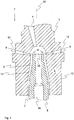
- FIG. 2 shows a spinneret 3 according to known prior art.
- the Garn Strukturselement 8 which also in the case of using the in the FIGS. 3 to 8 spinneret 3 according to the invention would be present, against the transport direction T and through a corresponding opening 7 in the vortex chamber 6.
- all of the spinnerets 3 shown in the figures have a vortex chamber wall 5 which, for example and at least in sections, can have a circular cross-section.
- the vortex chamber wall 5 has an outer side 12 delimiting the spinneret 3 to the outside and an inner side 13 delimiting the vortex chamber 6 (whereby the vortex chamber wall 5 could generally also be designed in several parts).
- spinning air channels 9 are present, via which during the Vorgarnher ein spinning air can be introduced into the vortex chamber 6, the spinning air channels 9 have a spinning air inlet opening 10 and an opening into the vortex chamber 6 spinning air outlet opening 11.
- FIG. 3 shows in principle a section along the line AA in FIG. 4 .
- the Anspinn Kunststoffkanäle 14 preferably comprise at least a first channel portion 17 and a second channel portion 18, the first channel portion 17, starting from the piecing air inlet opening 15 into the second channel section 18, which finally via the Anspinn Kunststoff-outlet opening 16 into the vortex chamber 6 opens.
- Both channel sections 17, 18 in this case enclose an angle ⁇ , the amount of which is preferably in the range lying in the general description.
- the first channel section 17 extends parallel to a central axis 32 of the spinneret 3, as also shown in FIG FIG. 3 is shown.
- the said channel sections 17, 18 can now be prepared by a respective bore, which intersect within the duct wall.
- the Anspinn Kunststoff inlet opening 15 introduced piecing air (based on FIG. 5 ) exits upwardly or outwardly from the Anspinn Kunststoffkanal 14, it is provided, the individual channel sections 17, 18 as in FIG. 6 shown to close.
- appropriate seals 20 may be used, which consist for example of plastic and can be glued into said holes. The result is a Anspinn Kunststoffkanal 14, which allows despite the production by drilling an air deflection within the Wirbelcrowandung 5.
- the Anspinn Kunststoff seen in the transport direction T can be introduced after the piecing air outlet openings 16 via the Anspinn Kunststoff-inlet openings 15 so that the Anspinnluft inlet openings 15 can be placed almost anywhere on the outer side 12 of the spinneret 3.
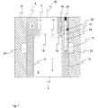
- FIG. 7 One to the Figures 5 and 6 alternative placement of Anspinn Kunststoff-inlet openings 15 shows FIG. 7 , As can be seen from this figure, the Anspinn Kunststoff-inlet openings 15 are not arranged in the region of an end face of the spinneret 3, but in the region of its running between the two end faces outside 12, wherein the Anspinn Kunststoff inlet openings 15 also by (preferably perpendicular to the central axis 32 of the spinneret 3 extending) holes are formed. Further is FIG.
- the spinneret 3 is preferably held in a carrier element 21 of the air-spinning machine, which of course should have holding elements or fastening elements, not shown, in order to be able to fix the spinneret 3 (the illustration in FIG. 7 is therefore only to be understood schematically).
- the carrier element 21 in turn has a Anspinn Kunststoffhunt 23, which may be formed, for example, as the spinneret 3 surrounding annular groove and which is not shown at location with a compressed air supply in combination to bring about the Anspinn Kunststoffäle 14 compressed air into the vortex chamber 6.
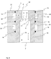
- FIG. 8 shows the execution according to FIG. 7 ,
- the cut was made by the corresponding spinneret 3 not by a Anspinn Kunststoffkanal 14, but a spinning air channel 9.
- the cut was made along a line from the placement of the line BB in FIG. 4 corresponds (even if the execution according to FIG. 4 in some respects from the execution according to FIG. 8 differs).
- FIG. 8 shown and explained in more detail below features also in the spinneret 3 according to FIG. 7 are present, even if these are in FIG. 7 for reasons of clarity are partly not shown.
- the spinneret 3 according to the invention a plurality of spinning air channels 9, over the during the piecing process following normal operation of the air spinning spinning air into the vortex chamber 6 can be introduced to produce a roving 1 from the supplied fiber structure 2.
- the spinning air channels 9 can also be formed by bores, wherein these each, preferably inclined in the transport direction T, from a spinning air inlet opening 10 placed in the region of the outer side 12 of the spinneret 3 to a spinning air outlet opening 11 of the spinneret located in the region of the inner side 13 3 and communicate with a spinning air channel 9 in connection.
- This can also be designed as an annular groove and communicates with a separate source of air pressure.
- a spinneret 3 is obtained in which the spinning air outlet openings 11 and the piecing air outlet openings 16 lie approximately in one plane. Nevertheless, the spinning air and the piecing air can be introduced via separate air chambers (spinning air chamber 22, Anspinn Kunststoffhunt 23), which are seen in the transport direction T spaced from each other.
Landscapes
- Engineering & Computer Science (AREA)
- Mechanical Engineering (AREA)
- Textile Engineering (AREA)
- Spinning Or Twisting Of Yarns (AREA)
Claims (15)
- Filière pour une machine à filer à jet d'air servant à fabriquer des mèches (1) à partir d'un assemblage de fibres (2),- dans laquelle la filière (3) présente un orifice d'entrée (4) pour l'entrée de l'assemblage de fibres (2),- dans laquelle la filière (3) présente une chambre à tourbillon (6) limitée au moins partiellement par une paroi de chambre à tourbillon (5) et placée en aval de l'orifice d'entrée (4) dans une direction de transport (T) de l'assemblage de fibres (2), spécifiée à l'état installé de la filière (3),- dans laquelle la filière (3) présente une ouverture (7) espacée de l'orifice d'entrée (4) dans la direction de transport (T), un élément de formation de fil (8) étant introduit dans la chambre à tourbillon (6),- dans laquelle la filière (3) présente au moins un conduit d'air pour filature (9) permettant d'amener l'air à l'intérieur de la chambre à tourbillon (6), dans laquelle le conduit d'air pour filature (9) s'étend entre un orifice d'entrée d'air pour filature (10) et un orifice de sortie d'air pour filature (11), et l'orifice d'entrée d'air pour filature (10) est disposé au niveau d'une face extérieure (12) de la filière (3) et l'orifice de sortie d'air pour filature (11) est disposé au niveau d'une face intérieure (13) de la paroi de chambre à tourbillon (5) limitant la chambre à tourbillon (6), et l'orifice de sortie d'air pour filature (11) débouche sur la chambre à tourbillon (6),- dans laquelle la filière (3) présente au moins un conduit d'air de démarrage de filature (14) permettant également d'amener de l'air à l'intérieur de la chambre à tourbillon (6), dans laquelle le conduit d'air de démarrage de filature (14) s'étend entre un orifice d'entrée d'air de démarrage de filature (15) et un orifice de sortie d'air de démarrage de filature (16), et l'orifice d'entrée d'air de démarrage de filature (15) est disposé au niveau de ladite face extérieure (12) de la filière (3), et l'orifice de sortie d'air de démarrage de filature (16) est disposé au niveau de ladite face intérieure (13) de la paroi de chambre à tourbillon (5), et l'orifice de sortie d'air de démarrage de filature (16) débouche sur la chambre à tourbillon (6), et- dans laquelle l'orifice d'entrée d'air pour filature (10) et l'orifice d'entrée d'air de démarrage de filature (15) sont espacés l'un de l'autre dans ladite direction de transport (T),caractérisée en ce que le conduit d'air de démarrage de filature (14) s'étend à partir de son orifice d'entrée d'air de démarrage de filature (15) au moins en partie dans le sens contraire de la direction de transport (T).
- Filière selon la revendication précédente, caractérisée en ce que le conduit d'air de démarrage de filature (14) comprend une première section de conduit (17) s'étendant à partir de l'orifice d'entrée d'air de démarrage de filature (15) à l'intérieur de la paroi de chambre à tourbillon (5) au moins partiellement dans le sens contraire de la direction de transport (T), et en ce que le conduit d'air de démarrage de filature (14) comprend une deuxième section de conduit (18) s'étendant à partir de la première section de conduit (17) en direction de l'orifice de sortie d'air de démarrage de filature (16).
- Filière selon la revendication précédente, caractérisée en ce que la première section de conduit (17) forme avec un axe médian (32) de la filière (3) un angle mesurant entre 0° et 30°, de préférence entre 0° et 15°, et de plus grande préférence entre 0° et 10°.
- Filière selon la revendication 2 ou 3, caractérisée en ce que la première section de conduit (17) et/ou la deuxième section de conduit (18) présentent un axe médian s'étendant en ligne droite.
- Filière selon l'une quelconque des revendications 2 à 4, caractérisée en ce que la première section de conduit (17) et/ou la deuxième section de conduit (18) sont formées par un perçage introduit dans la filière (3) depuis la face extérieure (12) de la filière (3).
- Filière selon l'une quelconque des revendications 2 à 5, caractérisée en ce que la première section de conduit (17) et la deuxième section de conduit (18) sont formées par respectivement un perçage introduit dans la filière (3) depuis la face extérieure (12) de la filière (3), les perçages s'intersectant à l'intérieur de la paroi de chambre à tourbillon (5).
- Filière selon la revendication 5 ou 6, caractérisée en ce que les perçages sont fermés au moins d'un côté au niveau de la face extérieure (12) de la filière (3) par un joint hermétique (20), la deuxième section de conduit (18) se séparant de la première section de conduit (17) de préférence entre le joint hermétique (20) de la première section de conduit (17) et l'orifice d'entrée d'air de démarrage de filature (15).
- Filière selon l'une quelconque des revendications 2 à 7, caractérisée en ce que la deuxième section de conduit (18) se sépare de la première section de conduit (17) selon un angle α mesurant entre 40° et 80°, de préférence entre 45° et 75° et de plus grande préférence entre 50° et 70°.
- Filière selon l'une quelconque des revendications précédentes, caractérisée en ce que l'orifice d'entrée d'air de démarrage de filature (15), vu dans la direction de transport (T), est disposé après l'orifice de sortie d'air pour filature (11) et/ou l'orifice de sortie d'air de démarrage de filature (16), et/ou en ce que l'orifice d'entrée d'air de démarrage de filature (15), vu dans la direction de transport (T), est disposé après l'orifice d'entrée d'air pour filature (10).
- Filière selon l'une quelconque des revendications précédentes, caractérisée en ce que l'orifice de sortie d'air pour filature (11) et l'orifice de sortie d'air de démarrage de filature (16) sont disposés dans un plan commun s'étendant perpendiculairement à la direction de transport (T), ou vus dans la direction de transport (T), sont espacés l'un de l'autre de moins de 3 mm, de préférence de moins de 2 mm et de plus grande préférence de moins de 1 mm.
- Filière selon l'une quelconque des revendications précédentes, caractérisée en ce que l'orifice d'entrée d'air de démarrage de filature (15) et l'orifice de sortie d'air de démarrage de filature (16), vus dans la direction de transport (T), sont espacés l'un de l'autre d'au moins 4 mm, de préférence d'au moins 8 mm et de plus grande préférence d'au moins 12 mm, et/ou de moins de 30 mm, de préférence de moins de 25 mm et de plus grande préférence de moins de 20 mm.
- Machine à filer à jet d'air pour fabriquer des mèches (1) à partir d'un assemblage de fibres (2),- dans laquelle la machine à filer à jet d'air comprend au moins un poste de filature avec une filière (3) selon l'une quelconque des revendications précédentes, et- dans laquelle le poste de filature est réalisé pour appliquer à l'aide d'un courant d'air une rotation à un assemblage de fibres (2) amené à la filière (3) dans une direction de transport (T), à l'intérieur de la chambre à tourbillon (6) limitée au moins partiellement par la filière (3).
- Machine à filer à jet d'air selon la revendication précédente, caractérisée en ce que la filière (3) présente plusieurs conduits d'air pour filature (9) et plusieurs conduits d'air pour filature (14) espacés par rapport à ceux-ci dans la direction de transport (T), dans laquelle les orifices d'entrée d'air pour filature (10) des conduits d'air pour filature (9) et les orifices d'entrée d'air de démarrage de filature (15) des conduits d'air de démarrage de filature (14) sont séparés les uns des autres par des éléments d'étanchéité (19), de préférence sous la forme de bagues d'étanchéité.
- Machine à filer à jet d'air selon la revendication précédente, caractérisée en ce que les éléments d'étanchéité (19) sont placés sur une face extérieure (12) de la filière (3) et l'entourent de préférence de manière circonférentielle.
- Machine à filer à jet d'air selon la revendication 13 ou 14, caractérisée en ce que le poste de filature présente un élément de support (21) recevant la filière (3), dans laquelle l'élément de support (21) présente une chambre d'air pour filature (22) adjacente aux orifices d'entrée d'air pour filature (10) et se trouvant en communication fluidique avec ceux-ci, dans laquelle l'élément de support (21) présente une chambre d'air de démarrage de filature (23) adjacente aux orifices d'entrée d'air de démarrage de filature (15) et se trouvant en communication fluidique avec ceux-ci, et dans laquelle la chambre d'air et la chambre d'air de démarrage de filature sont séparées de manière hermétique à l'aide desdits éléments d'étanchéité (19) selon la revendication 13 ou 14.
Applications Claiming Priority (2)
| Application Number | Priority Date | Filing Date | Title |
|---|---|---|---|
| CH00900/14A CH709756A1 (de) | 2014-06-13 | 2014-06-13 | Spinndüse für eine Luftspinnmaschine sowie Luftspinnmaschine mit einer entsprechenden Spinndüse. |
| PCT/IB2015/000873 WO2015189674A1 (fr) | 2014-06-13 | 2015-06-08 | Buse de filage pour un métier à filer à jet d'air et métier à filer à jet d'air avec buse de filage correspondante |
Publications (2)
| Publication Number | Publication Date |
|---|---|
| EP3155151A1 EP3155151A1 (fr) | 2017-04-19 |
| EP3155151B1 true EP3155151B1 (fr) | 2019-12-04 |
Family
ID=53490001
Family Applications (1)
| Application Number | Title | Priority Date | Filing Date |
|---|---|---|---|
| EP15731667.0A Active EP3155151B1 (fr) | 2014-06-13 | 2015-06-08 | Buse de filage pour un métier à filer à jet d'air et métier à filer à jet d'air avec buse de filage correspondante |
Country Status (5)
| Country | Link |
|---|---|
| EP (1) | EP3155151B1 (fr) |
| JP (1) | JP6689259B2 (fr) |
| CN (1) | CN106460249B (fr) |
| CH (1) | CH709756A1 (fr) |
| WO (1) | WO2015189674A1 (fr) |
Families Citing this family (5)
| Publication number | Priority date | Publication date | Assignee | Title |
|---|---|---|---|---|
| CH712409A1 (de) * | 2016-04-29 | 2017-10-31 | Rieter Ag Maschf | Luftspinnmaschine sowie Verfahren zur Herstellung eines Garns. |
| DE102019103271A1 (de) * | 2019-02-11 | 2020-08-13 | Maschinenfabrik Rieter Ag | Spinndüse für eine Luftspinnmaschine sowie Verfahren zum Öffnen einer solchen |
| CN113122969A (zh) * | 2020-01-11 | 2021-07-16 | 邱丽遐 | 一种粗纱机 |
| CN112921466B (zh) * | 2021-01-26 | 2024-07-09 | 江苏柯能新材料有限公司 | 一种用于涤纶工业丝纤维膨化的喷嘴组件 |
| IT202100020786A1 (it) * | 2021-08-02 | 2023-02-02 | Savio Macch Tessili Spa | Unità di filatura di tipo air-jet con sistema di avviamento della filatura perfezionato e relativo metodo di avviamento della filatura di tipo air-jet |
Citations (2)
| Publication number | Priority date | Publication date | Assignee | Title |
|---|---|---|---|---|
| CN201574228U (zh) * | 2009-04-20 | 2010-09-08 | 浙江泰坦股份有限公司 | 一种纺纱装置 |
| WO2013003962A1 (fr) * | 2011-07-01 | 2013-01-10 | Maschinenfabrik Rieter Ag | Banc à broches destiné à fabriquer une mèche et procédé permettant de commencer à filer un assemblage de fibres |
Family Cites Families (15)
| Publication number | Priority date | Publication date | Assignee | Title |
|---|---|---|---|---|
| US3445995A (en) * | 1966-12-19 | 1969-05-27 | Leesona Corp | Strand twisting apparatus |
| DE2614442C2 (de) * | 1976-02-14 | 1994-05-19 | Goetzfried Geb Wieland Franzis | Vorrichtung zum pneumatischen Falschdrallspinnen eines Fadens |
| CH629857A5 (en) * | 1977-05-05 | 1982-05-14 | Toray Industries | Method for preventing starting difficulties in the purely mechanical production of core yarn and apparatus for carrying out the method |
| JPS6056817B2 (ja) | 1981-10-13 | 1985-12-12 | 村田機械株式会社 | 紡績糸 |
| JPS61119725A (ja) * | 1984-11-14 | 1986-06-06 | Toyoda Autom Loom Works Ltd | 結束紡績用空気加撚ノズル |
| JPH0253918A (ja) * | 1988-08-18 | 1990-02-22 | Murata Mach Ltd | 空気式紡績装置 |
| CA2005018A1 (fr) | 1988-12-12 | 1990-06-12 | Elbert F. Morrison | Filature de meche, sous vide |
| JPH0679752U (ja) * | 1993-04-26 | 1994-11-08 | 村田機械株式会社 | 紡績装置 |
| JP2003155630A (ja) * | 2001-09-05 | 2003-05-30 | Murata Mach Ltd | 紡績装置 |
| JP2003166132A (ja) * | 2001-11-28 | 2003-06-13 | Murata Mach Ltd | 紡績装置及び紡績方法 |
| EP1375709B1 (fr) * | 2002-06-21 | 2014-08-06 | Maschinenfabrik Rieter Ag | Procédé de rattache pour, ou rattachement dans, des postes de filature des métiers à filer à vortex d'air |
| DE10251727A1 (de) * | 2002-11-05 | 2004-05-13 | Deutsches Institut für Textil- und Faserforschung Stuttgart - Stiftung des öffentlichen Rechts | Verfahren und Vorrichtung zur Herstellung von Flyerlunte |
| CN1598102A (zh) * | 2004-07-29 | 2005-03-23 | 江南大学 | 旋流退捻空气捻接器用金属退捻管 |
| DE102007006674A1 (de) * | 2007-02-10 | 2008-08-14 | Oerlikon Textile Gmbh & Co. Kg | Luftspinnvorrichtung |
| DE102012101039A1 (de) * | 2012-02-09 | 2013-08-14 | Maschinenfabrik Rieter Ag | Luftspinnmaschine mit separaten Spinn- und Anspinndüsen |
-
2014
- 2014-06-13 CH CH00900/14A patent/CH709756A1/de not_active Application Discontinuation
-
2015
- 2015-06-08 WO PCT/IB2015/000873 patent/WO2015189674A1/fr not_active Ceased
- 2015-06-08 JP JP2017517436A patent/JP6689259B2/ja active Active
- 2015-06-08 EP EP15731667.0A patent/EP3155151B1/fr active Active
- 2015-06-08 CN CN201580031314.0A patent/CN106460249B/zh active Active
Patent Citations (2)
| Publication number | Priority date | Publication date | Assignee | Title |
|---|---|---|---|---|
| CN201574228U (zh) * | 2009-04-20 | 2010-09-08 | 浙江泰坦股份有限公司 | 一种纺纱装置 |
| WO2013003962A1 (fr) * | 2011-07-01 | 2013-01-10 | Maschinenfabrik Rieter Ag | Banc à broches destiné à fabriquer une mèche et procédé permettant de commencer à filer un assemblage de fibres |
Also Published As
| Publication number | Publication date |
|---|---|
| JP2017521578A (ja) | 2017-08-03 |
| JP6689259B2 (ja) | 2020-04-28 |
| WO2015189674A1 (fr) | 2015-12-17 |
| EP3155151A1 (fr) | 2017-04-19 |
| CN106460249A (zh) | 2017-02-22 |
| CH709756A1 (de) | 2015-12-15 |
| CN106460249B (zh) | 2019-08-20 |
Similar Documents
| Publication | Publication Date | Title |
|---|---|---|
| DE4447969B4 (de) | Spinnmaschine mit Saugluftleitmitteln zur Faserverband-Kondensation | |
| EP2726655B1 (fr) | Banc à broches destiné à fabriquer une mèche et procédé permettant de commencer à filer un assemblage de fibres | |
| EP2895646B1 (fr) | Poste de filage d'un métier à filer à jet d'air | |
| EP2895647B1 (fr) | Poste de filage d'un banc à broches | |
| EP2927355B1 (fr) | Poste de filage d'un métier à filer à jet d'air et embout pour la fixation sur une filière d'un métier à filer à jet d'air | |
| EP2511403B1 (fr) | Banc à broches pour la fabrication d'une mèche | |
| DE102007006674A1 (de) | Luftspinnvorrichtung | |
| WO2017187293A1 (fr) | Métier à filer à jet d'air et procédé de production d'un fil | |
| EP2944713A1 (fr) | Poste de filage d'une machine de filage à jet d'air et utilisation de celle-ci | |
| EP3155151A1 (fr) | Buse de filage pour un métier à filer à jet d'air et métier à filer à jet d'air avec buse de filage correspondante | |
| EP1786961A1 (fr) | Dispositif de filature a jet d'air | |
| DE102008006379A1 (de) | Luftspinnvorrichtung | |
| EP2454403B1 (fr) | Machine à filer à jet d'air | |
| EP1560960A1 (fr) | Procede et dispositif pour produire une meche | |
| CH674855A5 (fr) | ||
| EP3293294B1 (fr) | Élément de formation de fil et buse de filage pour un métier à filer à jet d'air | |
| EP3604646B1 (fr) | Unité de banc d'étirage | |
| EP3464691B1 (fr) | Élément de formation de fil pour une machine de pré-filage et machine de pré-filage équipée de cet élément | |
| DE102014112360A1 (de) | Garnbildungselement für eine Spinndüse einer Luftspinnmaschine, Luftspinnmaschine sowie Verfahren zum Betrieb einer solchen | |
| DE3444427C2 (de) | Vorrichtung zum Einführen eines Fadenendes in den Spinnzwickel einer Friktionsspinnvorrichtung | |
| DE4032117A1 (de) | Spinnmaschine zum pneumatischen falschdrallspinnen | |
| WO2020109554A1 (fr) | Paire de cylindres pour un dispositif d'étirage d'un métier à filer, comprenant un cylindre inférieur et un cylindre supérieur, ainsi que dispositif d'étirage de ce type | |
| WO2005040466A1 (fr) | Dispositif destine a produire un file a partir d'une meche de fibres discontinues | |
| DE3920813A1 (de) | Verfahren zum verspinnen von aufgeloesten fasern von linearer textiler struktur auf der grundlage von diskontinuierlichen fasern, und vorrichtung zur durchfuehrung des verfahrens | |
| DE3933114A1 (de) | Verfahren und vorrichtung zum falschdrallspinnen |
Legal Events
| Date | Code | Title | Description |
|---|---|---|---|
| STAA | Information on the status of an ep patent application or granted ep patent |
Free format text: STATUS: THE INTERNATIONAL PUBLICATION HAS BEEN MADE |
|
| PUAI | Public reference made under article 153(3) epc to a published international application that has entered the european phase |
Free format text: ORIGINAL CODE: 0009012 |
|
| STAA | Information on the status of an ep patent application or granted ep patent |
Free format text: STATUS: REQUEST FOR EXAMINATION WAS MADE |
|
| 17P | Request for examination filed |
Effective date: 20161208 |
|
| AK | Designated contracting states |
Kind code of ref document: A1 Designated state(s): AL AT BE BG CH CY CZ DE DK EE ES FI FR GB GR HR HU IE IS IT LI LT LU LV MC MK MT NL NO PL PT RO RS SE SI SK SM TR |
|
| AX | Request for extension of the european patent |
Extension state: BA ME |
|
| DAV | Request for validation of the european patent (deleted) | ||
| DAX | Request for extension of the european patent (deleted) | ||
| GRAP | Despatch of communication of intention to grant a patent |
Free format text: ORIGINAL CODE: EPIDOSNIGR1 |
|
| STAA | Information on the status of an ep patent application or granted ep patent |
Free format text: STATUS: GRANT OF PATENT IS INTENDED |
|
| INTG | Intention to grant announced |
Effective date: 20190628 |
|
| GRAS | Grant fee paid |
Free format text: ORIGINAL CODE: EPIDOSNIGR3 |
|
| GRAA | (expected) grant |
Free format text: ORIGINAL CODE: 0009210 |
|
| STAA | Information on the status of an ep patent application or granted ep patent |
Free format text: STATUS: THE PATENT HAS BEEN GRANTED |
|
| AK | Designated contracting states |
Kind code of ref document: B1 Designated state(s): AL AT BE BG CH CY CZ DE DK EE ES FI FR GB GR HR HU IE IS IT LI LT LU LV MC MK MT NL NO PL PT RO RS SE SI SK SM TR |
|
| REG | Reference to a national code |
Ref country code: GB Ref legal event code: FG4D Free format text: NOT ENGLISH |
|
| REG | Reference to a national code |
Ref country code: CH Ref legal event code: EP |
|
| REG | Reference to a national code |
Ref country code: AT Ref legal event code: REF Ref document number: 1209512 Country of ref document: AT Kind code of ref document: T Effective date: 20191215 |
|
| REG | Reference to a national code |
Ref country code: DE Ref legal event code: R096 Ref document number: 502015011142 Country of ref document: DE |
|
| REG | Reference to a national code |
Ref country code: IE Ref legal event code: FG4D Free format text: LANGUAGE OF EP DOCUMENT: GERMAN |
|
| REG | Reference to a national code |
Ref country code: NL Ref legal event code: MP Effective date: 20191204 |
|
| REG | Reference to a national code |
Ref country code: LT Ref legal event code: MG4D |
|
| PG25 | Lapsed in a contracting state [announced via postgrant information from national office to epo] |
Ref country code: LV Free format text: LAPSE BECAUSE OF FAILURE TO SUBMIT A TRANSLATION OF THE DESCRIPTION OR TO PAY THE FEE WITHIN THE PRESCRIBED TIME-LIMIT Effective date: 20191204 Ref country code: SE Free format text: LAPSE BECAUSE OF FAILURE TO SUBMIT A TRANSLATION OF THE DESCRIPTION OR TO PAY THE FEE WITHIN THE PRESCRIBED TIME-LIMIT Effective date: 20191204 Ref country code: NO Free format text: LAPSE BECAUSE OF FAILURE TO SUBMIT A TRANSLATION OF THE DESCRIPTION OR TO PAY THE FEE WITHIN THE PRESCRIBED TIME-LIMIT Effective date: 20200304 Ref country code: GR Free format text: LAPSE BECAUSE OF FAILURE TO SUBMIT A TRANSLATION OF THE DESCRIPTION OR TO PAY THE FEE WITHIN THE PRESCRIBED TIME-LIMIT Effective date: 20200305 Ref country code: BG Free format text: LAPSE BECAUSE OF FAILURE TO SUBMIT A TRANSLATION OF THE DESCRIPTION OR TO PAY THE FEE WITHIN THE PRESCRIBED TIME-LIMIT Effective date: 20200304 Ref country code: FI Free format text: LAPSE BECAUSE OF FAILURE TO SUBMIT A TRANSLATION OF THE DESCRIPTION OR TO PAY THE FEE WITHIN THE PRESCRIBED TIME-LIMIT Effective date: 20191204 Ref country code: LT Free format text: LAPSE BECAUSE OF FAILURE TO SUBMIT A TRANSLATION OF THE DESCRIPTION OR TO PAY THE FEE WITHIN THE PRESCRIBED TIME-LIMIT Effective date: 20191204 |
|
| PG25 | Lapsed in a contracting state [announced via postgrant information from national office to epo] |
Ref country code: HR Free format text: LAPSE BECAUSE OF FAILURE TO SUBMIT A TRANSLATION OF THE DESCRIPTION OR TO PAY THE FEE WITHIN THE PRESCRIBED TIME-LIMIT Effective date: 20191204 Ref country code: RS Free format text: LAPSE BECAUSE OF FAILURE TO SUBMIT A TRANSLATION OF THE DESCRIPTION OR TO PAY THE FEE WITHIN THE PRESCRIBED TIME-LIMIT Effective date: 20191204 |
|
| PG25 | Lapsed in a contracting state [announced via postgrant information from national office to epo] |
Ref country code: AL Free format text: LAPSE BECAUSE OF FAILURE TO SUBMIT A TRANSLATION OF THE DESCRIPTION OR TO PAY THE FEE WITHIN THE PRESCRIBED TIME-LIMIT Effective date: 20191204 |
|
| PG25 | Lapsed in a contracting state [announced via postgrant information from national office to epo] |
Ref country code: RO Free format text: LAPSE BECAUSE OF FAILURE TO SUBMIT A TRANSLATION OF THE DESCRIPTION OR TO PAY THE FEE WITHIN THE PRESCRIBED TIME-LIMIT Effective date: 20191204 Ref country code: EE Free format text: LAPSE BECAUSE OF FAILURE TO SUBMIT A TRANSLATION OF THE DESCRIPTION OR TO PAY THE FEE WITHIN THE PRESCRIBED TIME-LIMIT Effective date: 20191204 Ref country code: PT Free format text: LAPSE BECAUSE OF FAILURE TO SUBMIT A TRANSLATION OF THE DESCRIPTION OR TO PAY THE FEE WITHIN THE PRESCRIBED TIME-LIMIT Effective date: 20200429 Ref country code: ES Free format text: LAPSE BECAUSE OF FAILURE TO SUBMIT A TRANSLATION OF THE DESCRIPTION OR TO PAY THE FEE WITHIN THE PRESCRIBED TIME-LIMIT Effective date: 20191204 Ref country code: NL Free format text: LAPSE BECAUSE OF FAILURE TO SUBMIT A TRANSLATION OF THE DESCRIPTION OR TO PAY THE FEE WITHIN THE PRESCRIBED TIME-LIMIT Effective date: 20191204 Ref country code: CZ Free format text: LAPSE BECAUSE OF FAILURE TO SUBMIT A TRANSLATION OF THE DESCRIPTION OR TO PAY THE FEE WITHIN THE PRESCRIBED TIME-LIMIT Effective date: 20191204 |
|
| PG25 | Lapsed in a contracting state [announced via postgrant information from national office to epo] |
Ref country code: SM Free format text: LAPSE BECAUSE OF FAILURE TO SUBMIT A TRANSLATION OF THE DESCRIPTION OR TO PAY THE FEE WITHIN THE PRESCRIBED TIME-LIMIT Effective date: 20191204 Ref country code: IS Free format text: LAPSE BECAUSE OF FAILURE TO SUBMIT A TRANSLATION OF THE DESCRIPTION OR TO PAY THE FEE WITHIN THE PRESCRIBED TIME-LIMIT Effective date: 20200404 Ref country code: SK Free format text: LAPSE BECAUSE OF FAILURE TO SUBMIT A TRANSLATION OF THE DESCRIPTION OR TO PAY THE FEE WITHIN THE PRESCRIBED TIME-LIMIT Effective date: 20191204 |
|
| REG | Reference to a national code |
Ref country code: DE Ref legal event code: R097 Ref document number: 502015011142 Country of ref document: DE |
|
| PLBE | No opposition filed within time limit |
Free format text: ORIGINAL CODE: 0009261 |
|
| STAA | Information on the status of an ep patent application or granted ep patent |
Free format text: STATUS: NO OPPOSITION FILED WITHIN TIME LIMIT |
|
| PG25 | Lapsed in a contracting state [announced via postgrant information from national office to epo] |
Ref country code: DK Free format text: LAPSE BECAUSE OF FAILURE TO SUBMIT A TRANSLATION OF THE DESCRIPTION OR TO PAY THE FEE WITHIN THE PRESCRIBED TIME-LIMIT Effective date: 20191204 |
|
| 26N | No opposition filed |
Effective date: 20200907 |
|
| PG25 | Lapsed in a contracting state [announced via postgrant information from national office to epo] |
Ref country code: SI Free format text: LAPSE BECAUSE OF FAILURE TO SUBMIT A TRANSLATION OF THE DESCRIPTION OR TO PAY THE FEE WITHIN THE PRESCRIBED TIME-LIMIT Effective date: 20191204 Ref country code: PL Free format text: LAPSE BECAUSE OF FAILURE TO SUBMIT A TRANSLATION OF THE DESCRIPTION OR TO PAY THE FEE WITHIN THE PRESCRIBED TIME-LIMIT Effective date: 20191204 |
|
| PG25 | Lapsed in a contracting state [announced via postgrant information from national office to epo] |
Ref country code: MC Free format text: LAPSE BECAUSE OF FAILURE TO SUBMIT A TRANSLATION OF THE DESCRIPTION OR TO PAY THE FEE WITHIN THE PRESCRIBED TIME-LIMIT Effective date: 20191204 |
|
| REG | Reference to a national code |
Ref country code: CH Ref legal event code: PL |
|
| GBPC | Gb: european patent ceased through non-payment of renewal fee |
Effective date: 20200608 |
|
| PG25 | Lapsed in a contracting state [announced via postgrant information from national office to epo] |
Ref country code: LU Free format text: LAPSE BECAUSE OF NON-PAYMENT OF DUE FEES Effective date: 20200608 |
|
| REG | Reference to a national code |
Ref country code: BE Ref legal event code: MM Effective date: 20200630 |
|
| PG25 | Lapsed in a contracting state [announced via postgrant information from national office to epo] |
Ref country code: LI Free format text: LAPSE BECAUSE OF NON-PAYMENT OF DUE FEES Effective date: 20200630 Ref country code: FR Free format text: LAPSE BECAUSE OF NON-PAYMENT OF DUE FEES Effective date: 20200630 Ref country code: CH Free format text: LAPSE BECAUSE OF NON-PAYMENT OF DUE FEES Effective date: 20200630 Ref country code: IE Free format text: LAPSE BECAUSE OF NON-PAYMENT OF DUE FEES Effective date: 20200608 Ref country code: GB Free format text: LAPSE BECAUSE OF NON-PAYMENT OF DUE FEES Effective date: 20200608 |
|
| PG25 | Lapsed in a contracting state [announced via postgrant information from national office to epo] |
Ref country code: BE Free format text: LAPSE BECAUSE OF NON-PAYMENT OF DUE FEES Effective date: 20200630 |
|
| REG | Reference to a national code |
Ref country code: AT Ref legal event code: MM01 Ref document number: 1209512 Country of ref document: AT Kind code of ref document: T Effective date: 20200608 |
|
| PG25 | Lapsed in a contracting state [announced via postgrant information from national office to epo] |
Ref country code: AT Free format text: LAPSE BECAUSE OF NON-PAYMENT OF DUE FEES Effective date: 20200608 |
|
| PG25 | Lapsed in a contracting state [announced via postgrant information from national office to epo] |
Ref country code: MT Free format text: LAPSE BECAUSE OF FAILURE TO SUBMIT A TRANSLATION OF THE DESCRIPTION OR TO PAY THE FEE WITHIN THE PRESCRIBED TIME-LIMIT Effective date: 20191204 Ref country code: CY Free format text: LAPSE BECAUSE OF FAILURE TO SUBMIT A TRANSLATION OF THE DESCRIPTION OR TO PAY THE FEE WITHIN THE PRESCRIBED TIME-LIMIT Effective date: 20191204 |
|
| PG25 | Lapsed in a contracting state [announced via postgrant information from national office to epo] |
Ref country code: MK Free format text: LAPSE BECAUSE OF FAILURE TO SUBMIT A TRANSLATION OF THE DESCRIPTION OR TO PAY THE FEE WITHIN THE PRESCRIBED TIME-LIMIT Effective date: 20191204 |
|
| P01 | Opt-out of the competence of the unified patent court (upc) registered |
Effective date: 20230519 |
|
| PGFP | Annual fee paid to national office [announced via postgrant information from national office to epo] |
Ref country code: DE Payment date: 20250618 Year of fee payment: 11 |
|
| PGFP | Annual fee paid to national office [announced via postgrant information from national office to epo] |
Ref country code: TR Payment date: 20250530 Year of fee payment: 11 |
|
| PGFP | Annual fee paid to national office [announced via postgrant information from national office to epo] |
Ref country code: IT Payment date: 20250630 Year of fee payment: 11 |