EP3155233B1 - Moteur à turbine à gaz avec système de refroidissement à centrage de rotor dans un diffuseur d'échappement - Google Patents
Moteur à turbine à gaz avec système de refroidissement à centrage de rotor dans un diffuseur d'échappement Download PDFInfo
- Publication number
- EP3155233B1 EP3155233B1 EP14736196.8A EP14736196A EP3155233B1 EP 3155233 B1 EP3155233 B1 EP 3155233B1 EP 14736196 A EP14736196 A EP 14736196A EP 3155233 B1 EP3155233 B1 EP 3155233B1
- Authority
- EP
- European Patent Office
- Prior art keywords
- exhaust
- cooling
- gas turbine
- strut
- turbine engine
- Prior art date
- Legal status (The legal status is an assumption and is not a legal conclusion. Google has not performed a legal analysis and makes no representation as to the accuracy of the status listed.)
- Not-in-force
Links
- 238000001816 cooling Methods 0.000 title claims description 168
- 239000012809 cooling fluid Substances 0.000 claims description 22
- 238000011144 upstream manufacturing Methods 0.000 claims description 16
- 239000012080 ambient air Substances 0.000 claims description 8
- 238000010926 purge Methods 0.000 claims description 7
- 239000012530 fluid Substances 0.000 claims description 3
- 239000003570 air Substances 0.000 description 17
- 239000000446 fuel Substances 0.000 description 2
- 208000031872 Body Remains Diseases 0.000 description 1
- 230000006978 adaptation Effects 0.000 description 1
- 230000000694 effects Effects 0.000 description 1
- 238000010438 heat treatment Methods 0.000 description 1
- 239000002184 metal Substances 0.000 description 1
- 239000000203 mixture Substances 0.000 description 1
- 238000012986 modification Methods 0.000 description 1
- 230000004048 modification Effects 0.000 description 1
- 230000008646 thermal stress Effects 0.000 description 1
Images


Classifications
-
- F—MECHANICAL ENGINEERING; LIGHTING; HEATING; WEAPONS; BLASTING
- F02—COMBUSTION ENGINES; HOT-GAS OR COMBUSTION-PRODUCT ENGINE PLANTS
- F02C—GAS-TURBINE PLANTS; AIR INTAKES FOR JET-PROPULSION PLANTS; CONTROLLING FUEL SUPPLY IN AIR-BREATHING JET-PROPULSION PLANTS
- F02C7/00—Features, components parts, details or accessories, not provided for in, or of interest apart form groups F02C1/00 - F02C6/00; Air intakes for jet-propulsion plants
- F02C7/12—Cooling of plants
- F02C7/16—Cooling of plants characterised by cooling medium
- F02C7/18—Cooling of plants characterised by cooling medium the medium being gaseous, e.g. air
-
- F—MECHANICAL ENGINEERING; LIGHTING; HEATING; WEAPONS; BLASTING
- F01—MACHINES OR ENGINES IN GENERAL; ENGINE PLANTS IN GENERAL; STEAM ENGINES
- F01D—NON-POSITIVE DISPLACEMENT MACHINES OR ENGINES, e.g. STEAM TURBINES
- F01D25/00—Component parts, details, or accessories, not provided for in, or of interest apart from, other groups
- F01D25/08—Cooling; Heating; Heat-insulation
- F01D25/12—Cooling
- F01D25/125—Cooling of bearings
-
- F—MECHANICAL ENGINEERING; LIGHTING; HEATING; WEAPONS; BLASTING
- F01—MACHINES OR ENGINES IN GENERAL; ENGINE PLANTS IN GENERAL; STEAM ENGINES
- F01D—NON-POSITIVE DISPLACEMENT MACHINES OR ENGINES, e.g. STEAM TURBINES
- F01D25/00—Component parts, details, or accessories, not provided for in, or of interest apart from, other groups
- F01D25/08—Cooling; Heating; Heat-insulation
- F01D25/14—Casings modified therefor
-
- F—MECHANICAL ENGINEERING; LIGHTING; HEATING; WEAPONS; BLASTING
- F01—MACHINES OR ENGINES IN GENERAL; ENGINE PLANTS IN GENERAL; STEAM ENGINES
- F01D—NON-POSITIVE DISPLACEMENT MACHINES OR ENGINES, e.g. STEAM TURBINES
- F01D25/00—Component parts, details, or accessories, not provided for in, or of interest apart from, other groups
- F01D25/28—Supporting or mounting arrangements, e.g. for turbine casing
-
- F—MECHANICAL ENGINEERING; LIGHTING; HEATING; WEAPONS; BLASTING
- F01—MACHINES OR ENGINES IN GENERAL; ENGINE PLANTS IN GENERAL; STEAM ENGINES
- F01D—NON-POSITIVE DISPLACEMENT MACHINES OR ENGINES, e.g. STEAM TURBINES
- F01D25/00—Component parts, details, or accessories, not provided for in, or of interest apart from, other groups
- F01D25/30—Exhaust heads, chambers, or the like
-
- F—MECHANICAL ENGINEERING; LIGHTING; HEATING; WEAPONS; BLASTING
- F01—MACHINES OR ENGINES IN GENERAL; ENGINE PLANTS IN GENERAL; STEAM ENGINES
- F01D—NON-POSITIVE DISPLACEMENT MACHINES OR ENGINES, e.g. STEAM TURBINES
- F01D9/00—Stators
- F01D9/02—Nozzles; Nozzle boxes; Stator blades; Guide conduits, e.g. individual nozzles
- F01D9/04—Nozzles; Nozzle boxes; Stator blades; Guide conduits, e.g. individual nozzles forming ring or sector
-
- F—MECHANICAL ENGINEERING; LIGHTING; HEATING; WEAPONS; BLASTING
- F01—MACHINES OR ENGINES IN GENERAL; ENGINE PLANTS IN GENERAL; STEAM ENGINES
- F01D—NON-POSITIVE DISPLACEMENT MACHINES OR ENGINES, e.g. STEAM TURBINES
- F01D9/00—Stators
- F01D9/06—Fluid supply conduits to nozzles or the like
- F01D9/065—Fluid supply or removal conduits traversing the working fluid flow, e.g. for lubrication-, cooling-, or sealing fluids
-
- F—MECHANICAL ENGINEERING; LIGHTING; HEATING; WEAPONS; BLASTING
- F05—INDEXING SCHEMES RELATING TO ENGINES OR PUMPS IN VARIOUS SUBCLASSES OF CLASSES F01-F04
- F05D—INDEXING SCHEME FOR ASPECTS RELATING TO NON-POSITIVE-DISPLACEMENT MACHINES OR ENGINES, GAS-TURBINES OR JET-PROPULSION PLANTS
- F05D2220/00—Application
- F05D2220/30—Application in turbines
- F05D2220/32—Application in turbines in gas turbines
-
- F—MECHANICAL ENGINEERING; LIGHTING; HEATING; WEAPONS; BLASTING
- F05—INDEXING SCHEMES RELATING TO ENGINES OR PUMPS IN VARIOUS SUBCLASSES OF CLASSES F01-F04
- F05D—INDEXING SCHEME FOR ASPECTS RELATING TO NON-POSITIVE-DISPLACEMENT MACHINES OR ENGINES, GAS-TURBINES OR JET-PROPULSION PLANTS
- F05D2260/00—Function
- F05D2260/20—Heat transfer, e.g. cooling
- F05D2260/205—Cooling fluid recirculation, i.e. after cooling one or more components is the cooling fluid recovered and used elsewhere for other purposes
-
- F—MECHANICAL ENGINEERING; LIGHTING; HEATING; WEAPONS; BLASTING
- F05—INDEXING SCHEMES RELATING TO ENGINES OR PUMPS IN VARIOUS SUBCLASSES OF CLASSES F01-F04
- F05D—INDEXING SCHEME FOR ASPECTS RELATING TO NON-POSITIVE-DISPLACEMENT MACHINES OR ENGINES, GAS-TURBINES OR JET-PROPULSION PLANTS
- F05D2260/00—Function
- F05D2260/60—Fluid transfer
- F05D2260/601—Fluid transfer using an ejector or a jet pump
Definitions
- the present invention relates to gas turbine engines and, more particularly, to structures for providing thermal management to promote thermally-uniform conditions at the exhaust section and providing protection to limit heating of the outer case of a gas turbine engine.
- a gas turbine engine generally includes a compressor section, a combustor section, a turbine section and an exhaust section.
- the compressor section may induct ambient air and compress it.
- the compressed air from the compressor section enters one or more combustors in the combustor section.
- the compressed air is mixed with the fuel in the combustors, and the air-fuel mixture can be burned in the combustors to form a hot working gas.
- the hot working gas is routed to the turbine section where it is expanded through alternating rows of stationary airfoils and rotating airfoils and used to generate power that can drive a rotor.
- the expanded gas exiting the turbine section may then be exhausted from the engine via the exhaust section.
- bleed air comprising a portion of the compressed air obtained from one or more stages of the compressor may be used as cooling air for cooling components of the turbine section.
- Additional bleed air or an alternative cooling air source may also be supplied to portions of the exhaust section, such as to cool portions of the exhaust section and maintain a turbine exhaust case below a predetermined temperature through a forced convection air flow provided within an outer casing or other components of the engine.
- the cooling air supplied to the support struts and adjacent components of the turbine exhaust case is not sufficient.
- the strut at top dead center and adjacent struts are heated more than the strut a bottom dead center and the adjacent struts.
- a gas turbine engine having a rotor centering cooling system for cooling struts within an exhaust diffuser and turbine case to reduce tip rub during hot restarts is disclosed.
- the rotor centering cooling system may be positioned, in part, within struts in the exhaust diffuser downstream from a turbine assembly for limiting thermal gradients of a turbine case and between top and bottom struts to prevent the exhaust bearing body from becoming off-center during steady state operation as a result of the top struts and casing becoming hotter than the bottom struts.
- the rotor centering cooling system may reduce the temperature at the exhaust diffuser such that the thermal gradient between the top and bottom struts is reduced as compared to conventional systems.
- the cooling system may be used during steady state operation and during shutdown, with cooling air being supplied by an external fan to control temperature gradients.
- a gas turbine engine may include one or more exhaust diffusers positioned downstream from a turbine assembly, extending circumferentially around a central longitudinal axis of the gas turbine engine and having an increasing cross-sectional area from an upstream edge to a downstream edge.
- One or more struts may extend from the at least one exhaust diffuser radially inward to an inner exhaust diffuser housing forming a radially inner surface of the exhaust diffuser.
- the strut may include one or more internal cooling systems positioned within an outer wall forming the strut.
- the gas turbine engine may include a rotor centering cooling system formed from an exhaust cooling manifold in communication with the internal cooling system positioned within the outer wall forming the strut for supplying cooling fluid to the internal cooling system in the strut.
- the rotor centering cooling system may include a rotor centering cooling channel extending from an inlet in the exhaust cooling manifold, through a turbine casing exhaust flange to an outlet in a shroud cavity upstream from the at least one strut and radially outward from an outer wall forming the exhaust diffuser.
- the cooling fluid flowing through the rotor centering cooling channel entrains ambient air within the shroud cavity, thereby purging the shroud cavity and cooling the turbine casing exhaust flange.
- the exhaust cooling manifold may be positioned radially outward from the at least one strut.
- the rotor centering cooling system may also include one or more exhaust cooling plenums forming a circumferentially extending cooling channel radially outward from the outer wall forming the exhaust diffuser.
- the exhaust cooling manifold may be in fluid communication with the exhaust cooling manifold via one or more metering holes.
- the metering hole may be positioned within the turbine casing exhaust flange, thereby providing cooling to the turbine casing exhaust flange.
- the metering hole may have a radially extending width equal to a radially extending width of the exhaust cooling plenum at the turbine casing exhaust flange.
- the exhaust cooling plenum may be positioned upstream from the exhaust cooling manifold.
- the rotor centering cooling channel may extend upstream from the exhaust cooling manifold to the shroud cavity.
- the rotor centering cooling channel may extend from the exhaust cooling manifold to the shroud cavity and between the exhaust cooling manifold and the strut.
- the outlet of the rotor centering cooling channel may be formed from one or more slots.
- the outlet of the at least one rotor centering cooling channel has a circular cross-section.
- the gas turbine engine may include a plurality of struts.
- the gas turbine engine may include a top strut with a first side strut offset circumferentially to a first side and a second side strut offset to a second side that is in an opposite circumferential direction from the first side.
- the top strut, first side strut and second side strut may each have the one or more internal cooling systems and a rotor centering cooling system comprising an exhaust cooling manifold in communication with the internal cooling system positioned within the outer wall forming the strut for supplying cooling fluid to the internal cooling system in the strut.
- the rotor centering cooling system formed in each of the top strut, first side strut and second side strut include one or more rotor centering cooling channels extending from an inlet in the exhaust cooling manifold, through a turbine casing exhaust flange to an outlet in a shroud cavity upstream from the and radially outward from an outer wall forming the exhaust diffuser, wherein the cooling fluid flowing through the rotor centering cooling channel entrains ambient air within the shroud cavity, thereby purging the shroud cavity and cooling the turbine casing exhaust flange.
- the top strut, first side strut and second side strut all extend upwardly above a midline plane of the gas turbine engine that extends generally through the central longitudinal axis of the gas turbine engine.
- the rotor centering cooling system provides a twofold cooling to struts, exhaust flange and associated components to reduce thermal gradients and thermal stress to prevent turbine tip rub during hot restarts by preventing the exhaust bearing body from moving off-center.
- rotor centering cooling system Another advantage of the rotor centering cooling system is that the one or more inlets of the rotor centering cooling channel in the exhaust cooling manifold, which increases the flow of cooling fluids through the exhaust cooling manifold which promotes higher cooling fluid flow through the metering holes in the turbine casing exhaust flange, thus addressing selectively the top-to-bottom thermal gradient on the turbine casing exhaust flange area.
- the rotor centering cooling channel redirects the cooling air to flow through the turbine casing exhaust flange a second time as the cooling air is exhausted from the outlet in the turbine casing exhaust flange and into the shroud cavity where the cooling fluid entrains the ambient air in the shroud cavity to create an air mover or ejector effect.
- the ambient air in the shroud cavity can be energized such that the mass flow of cooling air supplied to cool the flange on the second-pass cooling significantly increases and purges the shroud cavity.
- the rotor centering cooling system may achieve circumferentially uniform metal temperatures in the turbine casing exhaust flange area.
- Still another advantage of the invention is that purging the shroud cavity suppresses any buoyancy-driven flows that may drive any top-to-bottom temperatures in the turbine casing exhaust flange area.
- pins within the internal cooling system in the struts may be adjusted to increase flow to compensate for the decrease in flow from the exhaust cooling manifold into the internal cooling system caused by the flow of cooling fluids into the rotor centering cooling channel.
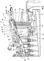
- a gas turbine engine 10 having a rotor centering cooling system 12 for cooling struts 14 within an exhaust diffuser 16 and turbine case to reduce tip rub during hot restarts is disclosed.
- the rotor centering cooling system 12 may be positioned, in part, within struts 14 in the exhaust diffuser 16 downstream from a turbine assembly 18 for limiting thermal gradients between top and bottom struts 20, 22 to prevent the exhaust bearing body 24 supporting the rotor 25 from becoming off-center during steady state operation as a result of the top struts 20 and casing becoming hotter than the bottom struts 22.
- the rotor centering cooling system 12 may reduce the temperature at the exhaust diffuser 16 such that the thermal gradient between the top and bottom struts 20, 22 is reduced as compared to conventional systems. As such, the exhaust bearing body 24 remains centered, thereby preventing a tighter turbine blade tip clearance 26 at the top 28 of the turbine assembly 18 than at the bottom 32 of the turbine assembly 18.
- the cooling system 12 may be used during steady state operation and during shutdown, with cooling air being supplied by an external fan to control temperature gradients.
- the gas turbine engine 10 may be formed from one or more exhaust diffusers 16, as shown in Figure 1 , positioned downstream from the turbine assembly 18 and extending circumferentially around a central longitudinal axis 34 of the gas turbine engine 10. As shown in Figures 1-5 , the exhaust diffuser 16 may have an increasing cross-sectional area from an upstream edge 36 to a downstream edge 38, as shown in Figure 1 .
- the gas turbine engine 10 may include one or more struts 14 extending from the exhaust diffuser 16 radially inward to an inner exhaust diffuser housing 40 forming a radially inner surface 42 of the exhaust diffuser 16.
- the strut 14 may include one or more internal cooling systems 44 positioned within an outer wall 46 forming the strut 14.
- the gas turbine engine 10 may also include one or more rotor centering cooling systems 12 for cooling struts 14 within an exhaust diffuser 16 to reduce tip rub during hot restarts.
- the rotor centering cooling system 12 may be formed from an exhaust cooling manifold 48 in communication with the internal cooling system 44 positioned within the outer wall 46 forming the strut 14 for supplying cooling fluid to the internal cooling system 44 in the strut 14.
- the rotor centering cooling system 12 may include one or more rotor centering cooling channels 60 extending from an inlet 50 in the exhaust cooling manifold 48, through a turbine casing exhaust flange 52 to an outlet 54 in a shroud cavity 56 upstream from the strut 14 and radially outward from an outer wall 58 forming the exhaust diffuser 16, such that the cooling fluid flowing through the rotor centering cooling channel 60 entrains ambient air within the shroud cavity 56, thereby purging the shroud cavity 56 and cooling the turbine casing exhaust flange 52.
- the exhaust cooling manifold 48 may be positioned radially outward from the strut 14.
- the rotor centering cooling channel 60 may extend upstream from the exhaust cooling manifold 48 to the shroud cavity 56.
- the rotor centering cooling channel 60 may extend from the exhaust cooling manifold 48 to the shroud cavity 56 and may be positioned between the exhaust cooling manifold 48 and the strut 14.
- the outlet 54 of the rotor centering cooling channel 60 may have a circular cross-section other appropriate configuration, as shown in Figure 8 .
- the outlet 54 may be formed from one or more slots 62.
- the slot 62 may be a thin slot shape, such as generally elliptical, oval or the like.
- the rotor centering cooling system 12 may also include one or more exhaust cooling plenums 64, as shown in Figures 1-5 , forming a circumferentially extending cooling channel radially outward from the outer wall 58 forming the exhaust diffuser 16.
- the exhaust cooling plenum 64 may have any appropriate configuration and size.
- the exhaust cooling plenum 64 may provide cooling fluid to the exhaust cooling manifold 48.
- the exhaust cooling plenum 64 may be positioned upstream from the exhaust cooling manifold 48.
- the exhaust cooling plenum 64 may be in fluid communication with the exhaust cooling manifold 48 via one or more metering holes 66.
- the metering hole 66 may be positioned within the turbine casing exhaust flange 52, thereby providing cooling to the turbine casing exhaust flange 52.
- the metering hole 66 may have a radially extending width equal to a radially extending width of the exhaust cooling plenum 64 at the turbine casing exhaust flange 52. As such, a high volume of cooling air may be passed through the turbine casing exhaust flange 52 to increase the cooling capacity of the rotor centering cooling system 12 over conventional systems.
- the gas turbine engine 10 may include a plurality of struts 14 extending from the exhaust diffuser 16 radially inward to the inner exhaust diffuser housing 40 forming the radially inner surface 42 of the exhaust diffuser 16.
- the gas turbine engine 10 may include a total of six struts 14, as shown in Figure 6 .
- three of the struts 14, such as a top strut 20, a first side strut 70 and second side strut 72, may be positioned above a midline plane 74 of the gas turbine engine 10 that extends generally through the central longitudinal axis 34 of the gas turbine engine 10.
- the top strut 20 may extend generally from the inner exhaust diffuser housing 40 to top dead center 28 of the outer wall 58 forming the exhaust diffuser 16. In other embodiments, the top strut 20 may be positioned in other positions.
- the first side strut 70 may be offset circumferentially to a first side 78 of the top strut 20 and may be positioned between the top strut 20 and the midline plane 74.
- the second side strut 72 may be offset to a second side 80 that is in an opposite circumferential direction from the first side 78 and may be positioned between the top strut 20 and the midline plane 74.
- the top strut 20, first side strut 70 and second side strut 72 each have an internal cooling system 44 and the rotor centering cooling system 12 providing cooling.
- Each of the top strut 20, first side strut 70 and second side strut 72 may include an exhaust cooling manifold 48 in communication with the internal cooling system 44 positioned within the outer walls 46 forming the struts 20, 70, 72 for supplying cooling fluid to the internal cooling system 44 in the struts 20, 70, 72.
- the cooling manifolds 48 for the struts 20, 70, 72 may or may not be in contact with each other.
- the rotor centering cooling channels 60 in the struts 20, 70, 72 may extend from inlets 50 in the exhaust cooling manifold 48, through the turbine casing exhaust flange 52 to the outlets 54 in the shroud cavity 56 upstream from the struts 20, 70, 72 and radially outward from the outer wall 58 forming the exhaust diffuser 16.
- the cooling fluid flowing through the rotor centering cooling channel 60 may entrain ambient air within the shroud cavity 56, thereby purging the shroud cavity 56 and cooling the turbine casing exhaust flange 52.
- the rotor centering cooling system 12 is configured such that cooling fluids from the exhaust cooling manifold 48 are passed through the turbine casing exhaust flange 52 at least twice.
- the cooling fluids flow through the turbine casing exhaust flange 52 first by flowing into the metering hole 66 and into the exhaust cooling manifold 48.
- the metering hole 66 is sized to increase cooling fluid flow into the exhaust cooling manifold 48.
- a portion of the cooling fluid flows into the internal cooling system 44 in the strut 14, and a portion of the cooling fluid in the exhaust cooling manifold 48 flows into the inlet 50 of the rotor centering cooling channel 60.
- the rotor centering cooling channel 60 routes the cooling fluid back through the turbine casing exhaust flange 52, thereby cooling the turbine casing exhaust flange 52 once again.
- the rotor centering cooling channel 60 may pass radially inward of the metering hole 66. The cooling fluid is then exhausted from the rotor centering cooling channel 60 through the outlet 54.
Landscapes
- Engineering & Computer Science (AREA)
- Mechanical Engineering (AREA)
- General Engineering & Computer Science (AREA)
- Chemical & Material Sciences (AREA)
- Combustion & Propulsion (AREA)
- Physics & Mathematics (AREA)
- Fluid Mechanics (AREA)
- Turbine Rotor Nozzle Sealing (AREA)
- Supercharger (AREA)
Claims (10)
- Moteur à turbine à gaz (10) ayant au moins un diffuseur d'échappement (16) positionné en aval d'un ensemble turbine (18), s'étendant de manière circonférentielle autour d'un axe longitudinal central (34) du moteur à turbine à gaz (10) et ayant une aire en section transversale augmentant d'un bord amont (36) à un bord aval (38) ;
au moins une entretoise (14) s'étendant à partir dudit au moins un diffuseur d'échappement (16) radialement vers l'intérieur jusqu'à un carter de diffuseur d'échappement interne (40) formant une surface radialement interne (42) du diffuseur d'échappement (16) ;
la turbine à gaz étant caractérisée en ce que :ladite au moins une entretoise (14) comporte au moins un système de refroidissement interne (44) positionné à l'intérieur d'une paroi externe (46) formant ladite au moins une entretoise (14) ; etun système de refroidissement de centrage de rotor (12) comprenant :un collecteur de refroidissement d'échappement (48) en communication avec ledit au moins un système de refroidissement interne (44), positionné à l'intérieur de la paroi externe (46) formant ladite au moins une entretoise (14) pour fournir un fluide de refroidissement audit au moins un système de refroidissement interne (44) dans ladite au moins une entretoise (14) ; etau moins un canal de refroidissement de centrage de rotor (60) s'étendant à partir d'une entrée (50) dans le collecteur de refroidissement d'échappement (48), à travers une bride d'échappement de carter de turbine (52) jusqu'à une sortie (54) dans une cavité de carénage (56) en amont de ladite au moins une entretoise (14) et radialement vers l'extérieur à partir d'une paroi externe (58) formant ledit au moins un diffuseur d'échappement (16), le fluide de refroidissement s'écoulant à travers ledit au moins un canal de refroidissement de centrage de rotor (60) entraînant de l'air ambiant à l'intérieur de la cavité de carénage (56), ce qui permet de purger la cavité de carénage (56) et de refroidir la bride d'échappement de carter de turbine (52). - Moteur à turbine à gaz (10) selon la revendication 1, caractérisé en ce que le collecteur de refroidissement d'échappement (48) est positionné radialement vers l'extérieur à partir de ladite au moins une entretoise (14).
- Moteur à turbine à gaz (10) selon la revendication 1, caractérisé en ce que le système de refroidissement de centrage de rotor (12) comprend en outre au moins un plénum de refroidissement d'échappement (64) formant un canal de refroidissement s'étendant de manière circonférentielle radialement vers l'extérieur à partir de la paroi externe (46) formant ledit au moins un diffuseur d'échappement (16), et le collecteur de refroidissement d'échappement (48) étant en communication fluidique avec le collecteur de refroidissement d'échappement (48) par le biais d'au moins un trou de dosage (66).
- Moteur à turbine à gaz (10) selon la revendication 3, caractérisé en ce que ledit au moins un trou de dosage (66) est positionné à l'intérieur de la bride d'échappement de carter de turbine (52), ce qui permet de produire le refroidissement de la bride d'échappement de carter de turbine (52).
- Moteur à turbine à gaz (10) selon la revendication 4, caractérisé en ce que ledit au moins un trou de dosage (66) a une largeur s'étendant radialement égale à une largeur s'étendant radialement du plénum de refroidissement d'échappement (64) au niveau de la bride d'échappement de carter de turbine (52).
- Moteur à turbine à gaz (10) selon la revendication 3, caractérisé en ce que ledit au moins un plénum de refroidissement d'échappement (64) est positionné en amont du collecteur de refroidissement d'échappement (48).
- Moteur à turbine à gaz (10) selon la revendication 1, caractérisé en ce que ledit au moins un canal de refroidissement de centrage de rotor (60) s'étend en amont à partir du collecteur de refroidissement d'échappement (48) jusqu'à la cavité de carénage (56).
- Moteur à turbine à gaz (10) selon la revendication 1, caractérisé en ce que ledit au moins un canal de refroidissement de centrage de rotor (60) s'étend à partir du collecteur de refroidissement d'échappement (48) jusqu'à la cavité de carénage (56) et entre le collecteur de refroidissement d'échappement (48) et ladite au moins une entretoise (14).
- Moteur à turbine à gaz (10) selon la revendication 1, caractérisé en ce que la sortie (54) dudit au moins un canal de refroidissement de centrage de rotor (60) est formée à partir d'au moins une fente (62) .
- Moteur à turbine à gaz (10) selon la revendication 1, caractérisé en ce que l'entretoise supérieure (20), la première entretoise latérale (70) et la deuxième entretoise latérale (72) s'étendent toutes vers le haut au-dessus d'un plan médian (74) du moteur à turbine à gaz (10) qui passe généralement par l'axe longitudinal central (34) du moteur à turbine à gaz (10).
Applications Claiming Priority (1)
| Application Number | Priority Date | Filing Date | Title |
|---|---|---|---|
| PCT/US2014/041649 WO2015191039A1 (fr) | 2014-06-10 | 2014-06-10 | Moteur à turbine à gaz avec système de refroidissement à centrage de rotor dans un diffuseur d'échappement |
Publications (2)
| Publication Number | Publication Date |
|---|---|
| EP3155233A1 EP3155233A1 (fr) | 2017-04-19 |
| EP3155233B1 true EP3155233B1 (fr) | 2019-01-02 |
Family
ID=51134392
Family Applications (1)
| Application Number | Title | Priority Date | Filing Date |
|---|---|---|---|
| EP14736196.8A Not-in-force EP3155233B1 (fr) | 2014-06-10 | 2014-06-10 | Moteur à turbine à gaz avec système de refroidissement à centrage de rotor dans un diffuseur d'échappement |
Country Status (5)
| Country | Link |
|---|---|
| US (1) | US10519862B2 (fr) |
| EP (1) | EP3155233B1 (fr) |
| JP (1) | JP6324548B2 (fr) |
| CN (1) | CN106460550B (fr) |
| WO (1) | WO2015191039A1 (fr) |
Families Citing this family (18)
| Publication number | Priority date | Publication date | Assignee | Title |
|---|---|---|---|---|
| US10330011B2 (en) * | 2013-03-11 | 2019-06-25 | United Technologies Corporation | Bench aft sub-assembly for turbine exhaust case fairing |
| FR3034465B1 (fr) * | 2015-04-03 | 2017-05-05 | Snecma | Turbomoteur comportant deux flux de ventilation distincts |
| CN105888849B (zh) * | 2016-04-06 | 2017-08-04 | 中国南方航空工业(集团)有限公司 | 引气冷却结构及具有该引气冷却结构的航空发动机 |
| DE102016217320A1 (de) | 2016-09-12 | 2018-03-15 | Siemens Aktiengesellschaft | Gasturbine mit getrennter Kühlung für Turbine und Abgasgehäuse |
| DE102017108597A1 (de) * | 2017-04-21 | 2018-10-25 | Rolls-Royce Deutschland Ltd & Co Kg | Strahltriebwerk mit einer Kühleinrichtung |
| US10727656B2 (en) * | 2017-11-08 | 2020-07-28 | Raytheon Technologies Corporation | Igniter cable conduit for gas turbine engine |
| US11230995B2 (en) | 2017-11-08 | 2022-01-25 | Raytheon Technologies Corporation | Cable conduit for turbine engine bypass |
| FR3075870B1 (fr) * | 2017-12-21 | 2021-09-17 | Safran Aircraft Engines | Aube fixe de turbomachine, dans un redresseur de soufflante |
| CN109653813B (zh) * | 2018-11-27 | 2019-08-23 | 中国航发沈阳发动机研究所 | 一种变几何涡轮冷气流路结构 |
| US11391179B2 (en) | 2019-02-12 | 2022-07-19 | Pratt & Whitney Canada Corp. | Gas turbine engine with bearing support structure |
| US11346249B2 (en) | 2019-03-05 | 2022-05-31 | Pratt & Whitney Canada Corp. | Gas turbine engine with feed pipe for bearing housing |
| CN110005631B (zh) * | 2019-04-22 | 2020-07-28 | 中国航发湖南动力机械研究所 | 离心叶轮后轴承冷却与封严结构 |
| PL431184A1 (pl) * | 2019-09-17 | 2021-03-22 | General Electric Company Polska Spółka Z Ograniczoną Odpowiedzialnością | Zespół silnika turbinowego |
| US11578621B2 (en) * | 2020-04-08 | 2023-02-14 | General Electric Company | System for cooling turbine shaft coupling |
| US11512599B1 (en) * | 2021-10-01 | 2022-11-29 | General Electric Company | Component with cooling passage for a turbine engine |
| EP4177445B1 (fr) * | 2021-11-05 | 2025-04-02 | ANSALDO ENERGIA S.p.A. | Ensemble couvercle de moyeu pour un carter de gaz d'échappement d'une turbine à gaz de grande puissance, turbine à gaz de grande puissance et procédé de modernisation d'une turbine à gaz de grande puissance |
| EP4198270B1 (fr) * | 2021-12-20 | 2026-01-28 | ANSALDO ENERGIA S.p.A. | Carter de gaz d'échappement pour un moteur à turbine à gaz à grande puissance, moteur à turbine à gaz à grande puissance et procédé de modification d'une turbine à gaz à grande puissance |
| JP2023100250A (ja) * | 2022-01-05 | 2023-07-18 | ゼネラル・エレクトリック・カンパニイ | 排気フレーム差動冷却システム |
Family Cites Families (14)
| Publication number | Priority date | Publication date | Assignee | Title |
|---|---|---|---|---|
| JPS56129725A (en) * | 1980-03-17 | 1981-10-12 | Hitachi Ltd | Method of cooling gas turbine and apparatus therefor |
| JPS59173527A (ja) * | 1983-03-22 | 1984-10-01 | Hitachi Ltd | ガスタ−ビン排気フレ−ム冷却空気系統 |
| JPS59173527U (ja) | 1983-05-07 | 1984-11-20 | 三菱重工業株式会社 | 切削液環流型のベツドとコラムを有する工作機械 |
| DE10303088B4 (de) * | 2002-02-09 | 2015-08-20 | Alstom Technology Ltd. | Abgasgehäuse einer Wärmekraftmaschine |
| US8157509B2 (en) | 2007-08-23 | 2012-04-17 | General Electric Company | Method, system and apparatus for turbine diffuser sealing |
| JP5118496B2 (ja) | 2008-01-10 | 2013-01-16 | 三菱重工業株式会社 | ガスタービンの排気部の構造およびガスタービン |
| JP5357659B2 (ja) | 2009-08-11 | 2013-12-04 | 三菱重工業株式会社 | ガスタービン |
| US8500392B2 (en) * | 2009-10-01 | 2013-08-06 | Pratt & Whitney Canada Corp. | Sealing for vane segments |
| JP4958967B2 (ja) * | 2009-12-15 | 2012-06-20 | 川崎重工業株式会社 | 換気構造を改良したガスタービンエンジン |
| US8979477B2 (en) * | 2011-03-09 | 2015-03-17 | General Electric Company | System for cooling and purging exhaust section of gas turbine engine |
| PL220729B1 (pl) * | 2011-10-03 | 2015-12-31 | Gen Electric | Układ turbiny gazowej |
| US9091171B2 (en) * | 2012-10-30 | 2015-07-28 | Siemens Aktiengesellschaft | Temperature control within a cavity of a turbine engine |
| US9316153B2 (en) * | 2013-01-22 | 2016-04-19 | Siemens Energy, Inc. | Purge and cooling air for an exhaust section of a gas turbine assembly |
| US9803501B2 (en) * | 2014-02-14 | 2017-10-31 | United Technologies Corporation | Engine mid-turbine frame distributive coolant flow |
-
2014
- 2014-06-10 WO PCT/US2014/041649 patent/WO2015191039A1/fr not_active Ceased
- 2014-06-10 CN CN201480079736.0A patent/CN106460550B/zh not_active Expired - Fee Related
- 2014-06-10 EP EP14736196.8A patent/EP3155233B1/fr not_active Not-in-force
- 2014-06-10 JP JP2016572556A patent/JP6324548B2/ja active Active
- 2014-06-10 US US15/316,716 patent/US10519862B2/en active Active
Non-Patent Citations (1)
| Title |
|---|
| None * |
Also Published As
| Publication number | Publication date |
|---|---|
| US20170138264A1 (en) | 2017-05-18 |
| CN106460550B (zh) | 2018-04-06 |
| JP2017522484A (ja) | 2017-08-10 |
| US10519862B2 (en) | 2019-12-31 |
| CN106460550A (zh) | 2017-02-22 |
| EP3155233A1 (fr) | 2017-04-19 |
| WO2015191039A1 (fr) | 2015-12-17 |
| JP6324548B2 (ja) | 2018-05-16 |
Similar Documents
| Publication | Publication Date | Title |
|---|---|---|
| EP3155233B1 (fr) | Moteur à turbine à gaz avec système de refroidissement à centrage de rotor dans un diffuseur d'échappement | |
| US10012106B2 (en) | Enclosed baffle for a turbine engine component | |
| CN106545365B (zh) | 喷嘴节段、喷嘴组件和燃气涡轮发动机 | |
| JP5723101B2 (ja) | ガスタービンエンジン温度管理の方法及び装置 | |
| US10392950B2 (en) | Turbine band anti-chording flanges | |
| US20210404344A1 (en) | Blade with tip rail cooling | |
| US20120082550A1 (en) | Apparatus and methods for cooling platform regions of turbine rotor blades | |
| US20180320530A1 (en) | Airfoil with tip rail cooling | |
| US10738791B2 (en) | Active high pressure compressor clearance control | |
| US8893512B2 (en) | Compressor bleed cooling fluid feed system | |
| EP2971602A1 (fr) | Système de commande de température de moteur à turbine ayant un élément chauffant pour un moteur à turbine à gaz | |
| CA2936582C (fr) | Modele d'element arriere d'aube de turbine | |
| EP3203024B1 (fr) | Asube rotorique et turbine à gaz associée | |
| US10329932B2 (en) | Baffle inserts | |
| US11519281B2 (en) | Impingement insert for a gas turbine engine | |
| EP3252270B1 (fr) | Système de refroidissement de buse pour moteur à turbine à gaz | |
| US10570773B2 (en) | Turbine shroud cooling | |
| US20180347374A1 (en) | Airfoil with tip rail cooling | |
| US10443407B2 (en) | Accelerator insert for a gas turbine engine airfoil | |
| CN108506048A (zh) | 用于涡轮发动机的膜孔布置 | |
| EP2587021A1 (fr) | Turbine à gaz et procédé pour guider un fluide compressé dans une turbine à gaz |
Legal Events
| Date | Code | Title | Description |
|---|---|---|---|
| STAA | Information on the status of an ep patent application or granted ep patent |
Free format text: STATUS: THE INTERNATIONAL PUBLICATION HAS BEEN MADE |
|
| PUAI | Public reference made under article 153(3) epc to a published international application that has entered the european phase |
Free format text: ORIGINAL CODE: 0009012 |
|
| STAA | Information on the status of an ep patent application or granted ep patent |
Free format text: STATUS: REQUEST FOR EXAMINATION WAS MADE |
|
| 17P | Request for examination filed |
Effective date: 20161117 |
|
| AK | Designated contracting states |
Kind code of ref document: A1 Designated state(s): AL AT BE BG CH CY CZ DE DK EE ES FI FR GB GR HR HU IE IS IT LI LT LU LV MC MK MT NL NO PL PT RO RS SE SI SK SM TR |
|
| AX | Request for extension of the european patent |
Extension state: BA ME |
|
| DAX | Request for extension of the european patent (deleted) | ||
| GRAP | Despatch of communication of intention to grant a patent |
Free format text: ORIGINAL CODE: EPIDOSNIGR1 |
|
| STAA | Information on the status of an ep patent application or granted ep patent |
Free format text: STATUS: GRANT OF PATENT IS INTENDED |
|
| INTG | Intention to grant announced |
Effective date: 20180919 |
|
| GRAS | Grant fee paid |
Free format text: ORIGINAL CODE: EPIDOSNIGR3 |
|
| GRAA | (expected) grant |
Free format text: ORIGINAL CODE: 0009210 |
|
| STAA | Information on the status of an ep patent application or granted ep patent |
Free format text: STATUS: THE PATENT HAS BEEN GRANTED |
|
| AK | Designated contracting states |
Kind code of ref document: B1 Designated state(s): AL AT BE BG CH CY CZ DE DK EE ES FI FR GB GR HR HU IE IS IT LI LT LU LV MC MK MT NL NO PL PT RO RS SE SI SK SM TR |
|
| REG | Reference to a national code |
Ref country code: GB Ref legal event code: FG4D |
|
| REG | Reference to a national code |
Ref country code: CH Ref legal event code: EP Ref country code: AT Ref legal event code: REF Ref document number: 1084638 Country of ref document: AT Kind code of ref document: T Effective date: 20190115 |
|
| REG | Reference to a national code |
Ref country code: IE Ref legal event code: FG4D |
|
| REG | Reference to a national code |
Ref country code: DE Ref legal event code: R096 Ref document number: 602014039110 Country of ref document: DE |
|
| REG | Reference to a national code |
Ref country code: NL Ref legal event code: MP Effective date: 20190102 |
|
| REG | Reference to a national code |
Ref country code: LT Ref legal event code: MG4D |
|
| REG | Reference to a national code |
Ref country code: AT Ref legal event code: MK05 Ref document number: 1084638 Country of ref document: AT Kind code of ref document: T Effective date: 20190102 |
|
| PG25 | Lapsed in a contracting state [announced via postgrant information from national office to epo] |
Ref country code: NL Free format text: LAPSE BECAUSE OF FAILURE TO SUBMIT A TRANSLATION OF THE DESCRIPTION OR TO PAY THE FEE WITHIN THE PRESCRIBED TIME-LIMIT Effective date: 20190102 |
|
| PG25 | Lapsed in a contracting state [announced via postgrant information from national office to epo] |
Ref country code: PT Free format text: LAPSE BECAUSE OF FAILURE TO SUBMIT A TRANSLATION OF THE DESCRIPTION OR TO PAY THE FEE WITHIN THE PRESCRIBED TIME-LIMIT Effective date: 20190502 Ref country code: FI Free format text: LAPSE BECAUSE OF FAILURE TO SUBMIT A TRANSLATION OF THE DESCRIPTION OR TO PAY THE FEE WITHIN THE PRESCRIBED TIME-LIMIT Effective date: 20190102 Ref country code: LT Free format text: LAPSE BECAUSE OF FAILURE TO SUBMIT A TRANSLATION OF THE DESCRIPTION OR TO PAY THE FEE WITHIN THE PRESCRIBED TIME-LIMIT Effective date: 20190102 Ref country code: PL Free format text: LAPSE BECAUSE OF FAILURE TO SUBMIT A TRANSLATION OF THE DESCRIPTION OR TO PAY THE FEE WITHIN THE PRESCRIBED TIME-LIMIT Effective date: 20190102 Ref country code: NO Free format text: LAPSE BECAUSE OF FAILURE TO SUBMIT A TRANSLATION OF THE DESCRIPTION OR TO PAY THE FEE WITHIN THE PRESCRIBED TIME-LIMIT Effective date: 20190402 Ref country code: SE Free format text: LAPSE BECAUSE OF FAILURE TO SUBMIT A TRANSLATION OF THE DESCRIPTION OR TO PAY THE FEE WITHIN THE PRESCRIBED TIME-LIMIT Effective date: 20190102 Ref country code: ES Free format text: LAPSE BECAUSE OF FAILURE TO SUBMIT A TRANSLATION OF THE DESCRIPTION OR TO PAY THE FEE WITHIN THE PRESCRIBED TIME-LIMIT Effective date: 20190102 |
|
| PG25 | Lapsed in a contracting state [announced via postgrant information from national office to epo] |
Ref country code: LV Free format text: LAPSE BECAUSE OF FAILURE TO SUBMIT A TRANSLATION OF THE DESCRIPTION OR TO PAY THE FEE WITHIN THE PRESCRIBED TIME-LIMIT Effective date: 20190102 Ref country code: GR Free format text: LAPSE BECAUSE OF FAILURE TO SUBMIT A TRANSLATION OF THE DESCRIPTION OR TO PAY THE FEE WITHIN THE PRESCRIBED TIME-LIMIT Effective date: 20190403 Ref country code: HR Free format text: LAPSE BECAUSE OF FAILURE TO SUBMIT A TRANSLATION OF THE DESCRIPTION OR TO PAY THE FEE WITHIN THE PRESCRIBED TIME-LIMIT Effective date: 20190102 Ref country code: IS Free format text: LAPSE BECAUSE OF FAILURE TO SUBMIT A TRANSLATION OF THE DESCRIPTION OR TO PAY THE FEE WITHIN THE PRESCRIBED TIME-LIMIT Effective date: 20190502 Ref country code: RS Free format text: LAPSE BECAUSE OF FAILURE TO SUBMIT A TRANSLATION OF THE DESCRIPTION OR TO PAY THE FEE WITHIN THE PRESCRIBED TIME-LIMIT Effective date: 20190102 Ref country code: BG Free format text: LAPSE BECAUSE OF FAILURE TO SUBMIT A TRANSLATION OF THE DESCRIPTION OR TO PAY THE FEE WITHIN THE PRESCRIBED TIME-LIMIT Effective date: 20190402 |
|
| REG | Reference to a national code |
Ref country code: DE Ref legal event code: R097 Ref document number: 602014039110 Country of ref document: DE |
|
| PG25 | Lapsed in a contracting state [announced via postgrant information from national office to epo] |
Ref country code: EE Free format text: LAPSE BECAUSE OF FAILURE TO SUBMIT A TRANSLATION OF THE DESCRIPTION OR TO PAY THE FEE WITHIN THE PRESCRIBED TIME-LIMIT Effective date: 20190102 Ref country code: IT Free format text: LAPSE BECAUSE OF FAILURE TO SUBMIT A TRANSLATION OF THE DESCRIPTION OR TO PAY THE FEE WITHIN THE PRESCRIBED TIME-LIMIT Effective date: 20190102 Ref country code: CZ Free format text: LAPSE BECAUSE OF FAILURE TO SUBMIT A TRANSLATION OF THE DESCRIPTION OR TO PAY THE FEE WITHIN THE PRESCRIBED TIME-LIMIT Effective date: 20190102 Ref country code: AT Free format text: LAPSE BECAUSE OF FAILURE TO SUBMIT A TRANSLATION OF THE DESCRIPTION OR TO PAY THE FEE WITHIN THE PRESCRIBED TIME-LIMIT Effective date: 20190102 Ref country code: RO Free format text: LAPSE BECAUSE OF FAILURE TO SUBMIT A TRANSLATION OF THE DESCRIPTION OR TO PAY THE FEE WITHIN THE PRESCRIBED TIME-LIMIT Effective date: 20190102 Ref country code: DK Free format text: LAPSE BECAUSE OF FAILURE TO SUBMIT A TRANSLATION OF THE DESCRIPTION OR TO PAY THE FEE WITHIN THE PRESCRIBED TIME-LIMIT Effective date: 20190102 Ref country code: AL Free format text: LAPSE BECAUSE OF FAILURE TO SUBMIT A TRANSLATION OF THE DESCRIPTION OR TO PAY THE FEE WITHIN THE PRESCRIBED TIME-LIMIT Effective date: 20190102 Ref country code: SK Free format text: LAPSE BECAUSE OF FAILURE TO SUBMIT A TRANSLATION OF THE DESCRIPTION OR TO PAY THE FEE WITHIN THE PRESCRIBED TIME-LIMIT Effective date: 20190102 |
|
| PLBE | No opposition filed within time limit |
Free format text: ORIGINAL CODE: 0009261 |
|
| STAA | Information on the status of an ep patent application or granted ep patent |
Free format text: STATUS: NO OPPOSITION FILED WITHIN TIME LIMIT |
|
| PG25 | Lapsed in a contracting state [announced via postgrant information from national office to epo] |
Ref country code: SM Free format text: LAPSE BECAUSE OF FAILURE TO SUBMIT A TRANSLATION OF THE DESCRIPTION OR TO PAY THE FEE WITHIN THE PRESCRIBED TIME-LIMIT Effective date: 20190102 |
|
| 26N | No opposition filed |
Effective date: 20191003 |
|
| REG | Reference to a national code |
Ref country code: DE Ref legal event code: R119 Ref document number: 602014039110 Country of ref document: DE |
|
| PG25 | Lapsed in a contracting state [announced via postgrant information from national office to epo] |
Ref country code: MC Free format text: LAPSE BECAUSE OF FAILURE TO SUBMIT A TRANSLATION OF THE DESCRIPTION OR TO PAY THE FEE WITHIN THE PRESCRIBED TIME-LIMIT Effective date: 20190102 |
|
| REG | Reference to a national code |
Ref country code: CH Ref legal event code: PL |
|
| GBPC | Gb: european patent ceased through non-payment of renewal fee |
Effective date: 20190610 |
|
| PG25 | Lapsed in a contracting state [announced via postgrant information from national office to epo] |
Ref country code: SI Free format text: LAPSE BECAUSE OF FAILURE TO SUBMIT A TRANSLATION OF THE DESCRIPTION OR TO PAY THE FEE WITHIN THE PRESCRIBED TIME-LIMIT Effective date: 20190102 |
|
| REG | Reference to a national code |
Ref country code: BE Ref legal event code: MM Effective date: 20190630 |
|
| PG25 | Lapsed in a contracting state [announced via postgrant information from national office to epo] |
Ref country code: TR Free format text: LAPSE BECAUSE OF FAILURE TO SUBMIT A TRANSLATION OF THE DESCRIPTION OR TO PAY THE FEE WITHIN THE PRESCRIBED TIME-LIMIT Effective date: 20190102 |
|
| PG25 | Lapsed in a contracting state [announced via postgrant information from national office to epo] |
Ref country code: IE Free format text: LAPSE BECAUSE OF NON-PAYMENT OF DUE FEES Effective date: 20190610 Ref country code: GB Free format text: LAPSE BECAUSE OF NON-PAYMENT OF DUE FEES Effective date: 20190610 Ref country code: DE Free format text: LAPSE BECAUSE OF NON-PAYMENT OF DUE FEES Effective date: 20200101 |
|
| PG25 | Lapsed in a contracting state [announced via postgrant information from national office to epo] |
Ref country code: CH Free format text: LAPSE BECAUSE OF NON-PAYMENT OF DUE FEES Effective date: 20190630 Ref country code: BE Free format text: LAPSE BECAUSE OF NON-PAYMENT OF DUE FEES Effective date: 20190630 Ref country code: LU Free format text: LAPSE BECAUSE OF NON-PAYMENT OF DUE FEES Effective date: 20190610 Ref country code: LI Free format text: LAPSE BECAUSE OF NON-PAYMENT OF DUE FEES Effective date: 20190630 |
|
| PG25 | Lapsed in a contracting state [announced via postgrant information from national office to epo] |
Ref country code: FR Free format text: LAPSE BECAUSE OF NON-PAYMENT OF DUE FEES Effective date: 20190630 |
|
| PG25 | Lapsed in a contracting state [announced via postgrant information from national office to epo] |
Ref country code: CY Free format text: LAPSE BECAUSE OF FAILURE TO SUBMIT A TRANSLATION OF THE DESCRIPTION OR TO PAY THE FEE WITHIN THE PRESCRIBED TIME-LIMIT Effective date: 20190102 |
|
| PG25 | Lapsed in a contracting state [announced via postgrant information from national office to epo] |
Ref country code: MT Free format text: LAPSE BECAUSE OF FAILURE TO SUBMIT A TRANSLATION OF THE DESCRIPTION OR TO PAY THE FEE WITHIN THE PRESCRIBED TIME-LIMIT Effective date: 20190102 Ref country code: HU Free format text: LAPSE BECAUSE OF FAILURE TO SUBMIT A TRANSLATION OF THE DESCRIPTION OR TO PAY THE FEE WITHIN THE PRESCRIBED TIME-LIMIT; INVALID AB INITIO Effective date: 20140610 |
|
| PG25 | Lapsed in a contracting state [announced via postgrant information from national office to epo] |
Ref country code: MK Free format text: LAPSE BECAUSE OF FAILURE TO SUBMIT A TRANSLATION OF THE DESCRIPTION OR TO PAY THE FEE WITHIN THE PRESCRIBED TIME-LIMIT Effective date: 20190102 |