EP3155285B1 - Scheibenbremse mit erregungsring - Google Patents
Scheibenbremse mit erregungsring Download PDFInfo
- Publication number
- EP3155285B1 EP3155285B1 EP15736630.3A EP15736630A EP3155285B1 EP 3155285 B1 EP3155285 B1 EP 3155285B1 EP 15736630 A EP15736630 A EP 15736630A EP 3155285 B1 EP3155285 B1 EP 3155285B1
- Authority
- EP
- European Patent Office
- Prior art keywords
- energizing ring
- disc
- energizing
- braking band
- connecting portion
- Prior art date
- Legal status (The legal status is an assumption and is not a legal conclusion. Google has not performed a legal analysis and makes no representation as to the accuracy of the status listed.)
- Active
Links
Images




Classifications
-
- B—PERFORMING OPERATIONS; TRANSPORTING
- B60—VEHICLES IN GENERAL
- B60T—VEHICLE BRAKE CONTROL SYSTEMS OR PARTS THEREOF; BRAKE CONTROL SYSTEMS OR PARTS THEREOF, IN GENERAL; ARRANGEMENT OF BRAKING ELEMENTS ON VEHICLES IN GENERAL; PORTABLE DEVICES FOR PREVENTING UNWANTED MOVEMENT OF VEHICLES; VEHICLE MODIFICATIONS TO FACILITATE COOLING OF BRAKES
- B60T8/00—Arrangements for adjusting wheel-braking force to meet varying vehicular or ground-surface conditions, e.g. limiting or varying distribution of braking force
- B60T8/32—Arrangements for adjusting wheel-braking force to meet varying vehicular or ground-surface conditions, e.g. limiting or varying distribution of braking force responsive to a speed condition, e.g. acceleration or deceleration
- B60T8/321—Arrangements for adjusting wheel-braking force to meet varying vehicular or ground-surface conditions, e.g. limiting or varying distribution of braking force responsive to a speed condition, e.g. acceleration or deceleration deceleration
- B60T8/329—Systems characterised by their speed sensor arrangements
-
- F—MECHANICAL ENGINEERING; LIGHTING; HEATING; WEAPONS; BLASTING
- F16—ENGINEERING ELEMENTS AND UNITS; GENERAL MEASURES FOR PRODUCING AND MAINTAINING EFFECTIVE FUNCTIONING OF MACHINES OR INSTALLATIONS; THERMAL INSULATION IN GENERAL
- F16D—COUPLINGS FOR TRANSMITTING ROTATION; CLUTCHES; BRAKES
- F16D65/00—Parts or details
- F16D65/02—Braking members; Mounting thereof
- F16D65/12—Discs; Drums for disc brakes
- F16D65/123—Discs; Drums for disc brakes comprising an annular disc secured to a hub member; Discs characterised by means for mounting
-
- F—MECHANICAL ENGINEERING; LIGHTING; HEATING; WEAPONS; BLASTING
- F16—ENGINEERING ELEMENTS AND UNITS; GENERAL MEASURES FOR PRODUCING AND MAINTAINING EFFECTIVE FUNCTIONING OF MACHINES OR INSTALLATIONS; THERMAL INSULATION IN GENERAL
- F16D—COUPLINGS FOR TRANSMITTING ROTATION; CLUTCHES; BRAKES
- F16D65/00—Parts or details
- F16D65/02—Braking members; Mounting thereof
- F16D65/12—Discs; Drums for disc brakes
- F16D65/125—Discs; Drums for disc brakes characterised by the material used for the disc body
-
- F—MECHANICAL ENGINEERING; LIGHTING; HEATING; WEAPONS; BLASTING
- F16—ENGINEERING ELEMENTS AND UNITS; GENERAL MEASURES FOR PRODUCING AND MAINTAINING EFFECTIVE FUNCTIONING OF MACHINES OR INSTALLATIONS; THERMAL INSULATION IN GENERAL
- F16D—COUPLINGS FOR TRANSMITTING ROTATION; CLUTCHES; BRAKES
- F16D65/00—Parts or details
- F16D65/02—Braking members; Mounting thereof
- F16D2065/13—Parts or details of discs or drums
- F16D2065/1304—Structure
- F16D2065/1316—Structure radially segmented
-
- F—MECHANICAL ENGINEERING; LIGHTING; HEATING; WEAPONS; BLASTING
- F16—ENGINEERING ELEMENTS AND UNITS; GENERAL MEASURES FOR PRODUCING AND MAINTAINING EFFECTIVE FUNCTIONING OF MACHINES OR INSTALLATIONS; THERMAL INSULATION IN GENERAL
- F16D—COUPLINGS FOR TRANSMITTING ROTATION; CLUTCHES; BRAKES
- F16D65/00—Parts or details
- F16D65/02—Braking members; Mounting thereof
- F16D2065/13—Parts or details of discs or drums
- F16D2065/134—Connection
- F16D2065/1344—Connection permanent, e.g. by casting
-
- F—MECHANICAL ENGINEERING; LIGHTING; HEATING; WEAPONS; BLASTING
- F16—ENGINEERING ELEMENTS AND UNITS; GENERAL MEASURES FOR PRODUCING AND MAINTAINING EFFECTIVE FUNCTIONING OF MACHINES OR INSTALLATIONS; THERMAL INSULATION IN GENERAL
- F16D—COUPLINGS FOR TRANSMITTING ROTATION; CLUTCHES; BRAKES
- F16D66/00—Arrangements for monitoring working conditions, e.g. wear, temperature
- F16D2066/003—Position, angle or speed
-
- G—PHYSICS
- G01—MEASURING; TESTING
- G01P—MEASURING LINEAR OR ANGULAR SPEED, ACCELERATION, DECELERATION, OR SHOCK; INDICATING PRESENCE, ABSENCE, OR DIRECTION, OF MOVEMENT
- G01P3/00—Measuring linear or angular speed; Measuring differences of linear or angular speeds
- G01P3/42—Devices characterised by the use of electric or magnetic means
- G01P3/44—Devices characterised by the use of electric or magnetic means for measuring angular speed
- G01P3/48—Devices characterised by the use of electric or magnetic means for measuring angular speed by measuring frequency of generated current or voltage
- G01P3/481—Devices characterised by the use of electric or magnetic means for measuring angular speed by measuring frequency of generated current or voltage of pulse signals
- G01P3/487—Devices characterised by the use of electric or magnetic means for measuring angular speed by measuring frequency of generated current or voltage of pulse signals delivered by rotating magnets
Definitions
- the present invention relates to a disc assembly for a disc brake and energizing ring, or flywheel.
- the present invention relates to an assembly in which the fly wheel is co-melted in the body of the disc for disc brakes.
- anti-lock braking systems in vehicles including cars, air and rail transport and commercial vehicles have been used for years.
- the need for such systems is particularly felt in the road haulage industry, especially for articulated vehicles to prevent loss of control, especially of trailers, and to avoid jack-knifing or skidding of the trailer when braking on slippery road surfaces.
- anti-lock braking systems use a detecting and control device of the wheel speed which produces signals representative of the wheel speed which are sent to a logic card of the system.
- the logic card calculates the speed of rotation and acceleration or deceleration of the wheel, detecting locking of the wheel and determining imminent slippage and therefore potential danger.
- the system further comprises valves modulating the pressure of the fluid of the braking system which, when activated, adjusts the braking.
- the logic card modulates the valves based on the relative rotation speed of the wheels to maintain the maximum braking pressure without inducing locking of the wheels.
- the most common type of detection device is a magnetic sensor operated by an energizing ring.
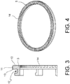
- the ring is a ring-shaped energizing structure fitted with teeth projecting from a side thereof.
- the energizing ring is fitted on an assembly typically comprising a disc brake rotor.
- the purpose of the present invention is therefore to propose a disc assembly and energizing ring which makes it possible to achieve the above mentioned requirements, as well as to solve the problems of prior art mentioned.
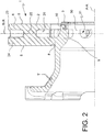
- a disc assembly 1 for disc brake and energizing ring, or flywheel comprises a disc for disc brake 2 which develops about a rotation axis defining an axial direction A-A, a radial direction R-R, orthogonal to said axial direction A-A, and a tangential or circumferential direction T-T perpendicular to said axial direction A-A and said radial direction R-R.
- said disc is made with a first, less corrosion-resistant material, such as laminated iron, but suitable to withstand thermal stress.
- Said disc 2 comprises a braking band 4 adapted to cooperate with opposite braking surfaces 5, 6 thereof with a brake caliper or calliper.
- Said disc 2 further comprises a bell 7 for connecting the brake disc 2 to a hub of a vehicle
- Said disc 2 comprises a connecting portion 8 between said braking band 4 and said bell 7.
- Said disc 2 further comprises a connecting portion of an energizing ring 9 connected cantilevered to said bell 7 so as to avoid interfering with said braking band 4 and forming an end surface 10 arranged parallel to the radial direction R-R.
- said connecting portion 9 is cantilevered axially A-A.
- said connecting portion 9 is connected to the bell 7 by means of mechanical decoupling bridges or spokes 30 between the connecting portion 9 and band 4, the spokes 30 between them forming large ventilation and thermal decoupling windows 31.
- Said assembly further comprising an energizing ring 3.
- Said ring 3 comprises an energizing ring body 11 having an energizing side 12, opposite said disc 2, and a coupling side 13, facing said disc 2.
- Said energizing ring 3 comprises a plurality of projections and/or recesses 14 provided in said energizing side 12.
- said projections or recesses 14 are a plurality of equi-spaced projections or recesses and circumferentially distributed along said energizing side 12 of an annular shape. According to one embodiment, said projections or recesses 14 project in an axial direction A-A.
- said energizing ring 3 is in a second, more corrosion-resistant material than said first disc material 2, such as steel, particularly stainless steel.
- At least a coupling portion 15 cantilevers from said energizing ring body 11 in an axial direction A-A and includes a free end portion 16.
- said coupling portion 15 is a plurality of axially projecting feet.
- said coupling portion 15 is an annular axial extension.
- said free end portion 16 of the coupling portion 15 is received or buried in said connecting portion of an energizing ring 9 of the disc 2 passing through said radial end surface 10.
- said connecting portion of an energizing ring 9 closely surrounds said free end portion 16 of the coupling portion 15, leaving said energizing ring body 11 free, substantially cantilevered, creating a mechanical and thermal decoupling, while maintaining a firm anchorage to the disc.
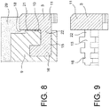
- said free end portion 16 of the coupling portion 15 includes undercut portions 17 closely surrounded by the material of the connecting portion of an energizing ring 9 of the disc 2 forming a close, non-detachable geometric mating.
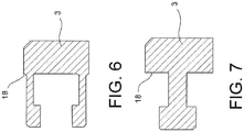
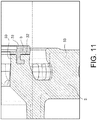
- said energizing ring body 11 comprises at least a core support portion 18 which cantilevers radially outwardly from the radial footprint of said radial end surface 10 of the connecting portion of an energizing ring 9 ( figure 8 ) .
- a radially outer side 19 of the energizing ring body 11 comprises at least one conical stretch 20 which tapers in the axial direction A-A passing from said energizing side 12 to said coupling side 13 ( figure 10A ).
- said coupling portion 15 comprises a neck stretch 22 connected to said energizing ring body 11 which continues in a free end portion 16.
- said energizing ring body 11 and said radial end surface 10 of said connecting portion of an energizing ring 9 are reciprocally spaced apart by a clearance 21 and are connected to each other only by said neck 22 of the coupling portion 15, leaving said body 11 cantilevered ( figure 8 ).
- said braking band 4 and said bell 7 are in one piece.
- said braking band is of cast iron, for example laminar cast iron or flake graphite cast iron, and said energizing ring 3 is made of steel, such as stainless steel.
- said braking band 4 is of cast iron, for example laminar cast iron or flake graphite cast iron, said bell 7 is of aluminium and said energizing ring 3 is made of steel, such as stainless steel.
- said disc 2 is obtained by comelting or co-melting, incorporating said free end portion 16 of said energizing ring 3.
- said bell 7 is obtained by comelting, connecting itself to said braking band 4 via said connecting portion between said braking band and said bell 8 and incorporating said free end portion 16 of said energizing ring 3.
- said braking band 4 is a single hub braking band.
- said braking band 4 is a ventilated braking band comprising two plates or hubs 23, 24 connected together by connecting elements 25 forming a radial ventilation conduit 26 for the cooling of the braking band 4.
- Method of production of a disc assembly 1 for disc brake and energizing ring comprising the steps of:
- Said method comprises, according to a possible procedure, the further step in which said energizing ring 3 is in hot-melting material and in a more corrosion-resistant material.
- Said method comprises, according to a possible procedure, the further step in which a mould 27 is provided having a cavity 28 of suitable shape to form a disc for disc brake 2 which develops about a rotation axis defining an axial direction A-A, a radial direction R-R, orthogonal to said axial direction A-A, and a tangential or circumferential direction T-T orthogonal to said axial direction A-A and said radial direction R-R; and a braking band 4 adapted to cooperate with opposite braking surfaces 5, 6 thereof with a brake caliper; as well as a bell 7 for connecting the brake disc 2 to a hub of a vehicle; said cavity being of suitable shape to form a connecting portion 8 between said braking band 4 and said bell 7 and a connecting portion of an energizing ring 9 connected cantilevered to said bell 7 so as not to interfere with said braking band 4 and forming an end surface 10 arranged parallel to the radial direction R-R.
- Said method comprises, according to a possible procedure, the further step in which said free end portion 16 of said energizing ring 3 is inserted in said cavity 28 so that said free end 16 can receive around itself and closely in contact low-melting material melted in said cavity 28, low-melting material or material melting at a lower temperature than said hot-melting material of the energizing ring 3.
- Said method comprises according to a possible procedure, the further step in which low-melting material less resistant to corrosion than said material of the energizing ring is cast in said cavity 28 forming said disc 2 and incorporating and burying said free end 16 in said connecting portion of an energizing ring 9.
- Said method alternatively provides that said step of providing an energizing ring 3 provides for leaving allowance for machining 33 on said ring.
- Said method alternatively provides, following the formation of the disc 2 and following the extraction of the formed disc from the mould 27, for the processing of the energizing ring 3 and in particular of the energizing side 12 for perfectly forming in the desired size and tolerances said plurality of projections and/or recesses 14, for example, by chip removal processing.
- Said method alternatively provides that said cavity of said mould is made so as to form a disc of a disc brake 2 with an allowance for machining 33.
- Said method alternatively provides, following the formation of the disc 2 and following the extraction of the formed disc from the mould 27, for the processing of the disc, for example the braking band and the coupling surfaces of the disc and/or the bell to the hub, for example by chip removal processing so as to bring said surfaces to the desired size and tolerances.
- Said method alternatively provides that said energizing ring 3 is supported by a foundry core 29 adapted to be inserted into said mould and to form the undercuts of the disc for disc brake 2.
- Said method alternatively provides that said core 29 has a support surface 30 for said energizing ring whereon said energizing ring 3 is arranged and said energizing ring 3 is supported with said free end portion 16 thereof that cantilevers into said cavity 28 to be buried in the low-melting material of the disc 2.
- Said method alternatively provides that before inserting said energizing ring 3 partially in said cavity 28, said coupling side 13 is covered with a suitable material to prevent the close contact of the low-melting material of the disc with said energizing ring body 11, for example with a layer of graphite 32.
- Said method alternatively provides that, following the formation of the disc 2 and following the extraction of the formed disc from the mould 27, the graphite 32 is removed, for example by vibration, forming a clearance 21 between said coupling side 13 and said radial end surface 10 of said connecting portion of an energizing ring 9.
- Said method alternatively provides that said body 11 of said energizing ring 3 is left cantilevered with respect to said radial end surface 10 of said connecting portion of an energizing ring 9.
- the present invention also relates to a vehicle, such as a commercial vehicle, comprising an assembly according to any of the above-described embodiments.
Landscapes
- Engineering & Computer Science (AREA)
- General Engineering & Computer Science (AREA)
- Mechanical Engineering (AREA)
- Transportation (AREA)
- Physics & Mathematics (AREA)
- General Physics & Mathematics (AREA)
- Braking Arrangements (AREA)
Claims (11)
- Scheibenanordnung (1) für eine Scheibenbremse und einen Antriebsring, oder ein Schwungrad, umfassend:- eine Scheibe für eine Scheibenbremse (2), welche sich um eine Rotationsachse entwickelt, welche eine axiale Richtung (A-A), eine radiale Richtung (R-R), orthogonal zu der axialen Richtung (A-A), und eine tangentiale oder Umfangsrichtung (T-T) rechtwinklig zu der axialen Richtung (A-A) und der radialen Richtung (R-R) definiert;- wobei die Scheibe (2) aus einem ersten Material ist, welches eine geringe Widerstandsfähigkeit gegenüber Korrosion aufweist, und umfasst:- ein Bremsband (4), welches dazu eingerichtet ist, mit gegenüberliegenden Bremsflächen (5, 6) davon mit einem Bremssattel zusammen zu wirken;- eine Glocke (7) zum Verbinden der Bremsscheibe (2) mit einer Nabe eines Fahrzeugs;- einen Verbindungsabschnitt (8) zwischen dem Bremsband (4) und der Glocke (7);- einen Verbindungsabschnitt eines Antriebsrings (9), welcher mit der Glocke (7) auskragend verbunden ist, um zu verhindern, dass er das Bremsband (4) beeinträchtigt, und welcher eine Endfläche (10) bildet, parallel zu der radialen Richtung (R-R) angeordnet;- wobei die Anordnung ferner einen Antriebsring (3) umfasst, welcher umfasst:- einen Antriebsringkörper (11), welcher eine Antriebsseite (12), der Scheibe (2) gegenüberliegend, und eine Kopplungsseite (13) aufweist, welche zu der Scheibe (2) weist;- eine Mehrzahl von Vorsprüngen und/oder Ausnehmungen (14), welche in der Antriebsseite (12) bereitgestellt sind;- wobei der Antriebsring aus einem zweiten Material ist, welches gegenüber Korrosion widerstandsfähiger ist als das erste Material;- wobei wenigstens ein Kopplungsabschnitt (15) von dem Antriebsringkörper (11) in einer axialen Richtung (A-A) auskragt und einen freien Endabschnitt (16) umfasst;dadurch gekennzeichnet, dass- der freie Endabschnitt (16) des Kopplungsabschnitts (15), welcher in dem Verbindungsabschnitt eines Antriebsrings (9) der Scheibe (2) aufgenommen ist, durch die radiale Endfläche (10) tritt;- der Verbindungsabschnitt eines Antriebsrings (9) den freien Endabschnitt (16) des Kopplungsabschnitts (15) eng umgibt, wobei er den Antriebsringkörper (11) frei lässt.
- Anordnung (1) nach Anspruch 1, wobei- der freie Endabschnitt (16) des Kopplungsabschnitts (15) Hinterschnittabschnitte (17) umfasst, welche durch das Material des Verbindungsabschnitts eines Antriebsrings (9) der Scheibe (2) eng umgeben sind, welche eine enge nicht-lösbare geometrische Passung bilden.
- Anordnung (1) nach einem der vorhergehenden Ansprüche, wobei- der Antriebsringkörper (11) wenigstens einen Kerntrageabschnitt (18) umfasst, welcher von dem radialen Umriss der radialen Endfläche (10) des Verbindungsabschnitts eines Antriebsrings (9) radial nach außen auskragt.
- Anordnung (1) nach einem der vorhergehenden Ansprüche, wobei- eine radial äußere Seite (19) des Antriebsringkörpers (11) wenigstens eine konische Strecke (20) umfasst, welche sich in der axialen Richtung (A-A) von der Antriebsseite (12) zu der Kopplungsseite (13) durchtretend verjüngt.
- Anordnung (1) nach einem der vorhergehenden Ansprüche, wobei- zwischen dem Antriebsringkörper (11) und der radialen Endfläche (10) des Verbindungsabschnitts eines Antriebsrings (9) der Scheibe (2) ein Freiraum (21) mit der Ausnahme der Strecke vorliegt, den Kopplungsabschnitt (15) bildend; und/oder wobei- der Kopplungsabschnitt (15) eine Halsstrecke (22) umfasst, welche mit dem Antriebsringkörper (11) verbunden ist, welche in einem freien Endabschnitt (16) fortfährt, und wobei- der Antriebsringkörper (11) und die radiale Endfläche (10) des Verbindungsabschnitts eines Antriebsrings (9) wechselseitig durch einen Freiraum (21) voneinander beabstandet und miteinander nur durch den Hals (22) des Kopplungsabschnitts (15) verbunden sind.
- Anordnung (1) nach einem der vorhergehenden Ansprüche, wobei das Bremsband (4) und die Glocke (7) einstückig sind; und/oder wobei- das Bremsband aus Gusseisen, zum Beispiel laminarem Gusseisen oder Lamellengraphit-Gusseisen, ist und der Antriebsring (3) aus Stahl, wie beispielsweise rostfreiem Stahl, hergestellt ist; und/oder wobei- das Bremsband (4) aus Gusseisen, zum Beispiel laminarem Gusseisen oder Lamellengraphit-Gusseisen, ist, die Glocke (7) aus Aluminium ist und der Antriebsring (3) aus Stahl, wie beispielsweise rostfreiem Stahl, hergestellt ist; und/oder wobei- die Scheibe (2) durch Zusammenschmelzen erhalten wird, wobei der freie Endabschnitt (16) des Antriebsrings (3) eingeschlossen wird; und/oder wobei- die Glocke (7) durch Zusammenschmelzen erhalten wird, wobei sie mit dem Bremsband (4) über den Verbindungsabschnitt zwischen dem Bremsband und der Glocke (8) verbunden wird und der freie Endabschnitt (16) des Antriebsrings (3) eingeschlossen wird; und/oder wobei- das Bremsband (4) ein Einzelnaben-Bremsband ist; und/oder wobei- das Bremsband (4) ein belüftetes Bremsband ist, welches zwei Platten oder Naben (23, 24) umfasst, welche miteinander durch Verbindungselemente (25) verbunden sind, welche eine radiale Belüftungsleitung (26) für das Kühlen des Bremsbands (4) bilden.
- Verfahren zum Herstellen einer Scheibenanordnung (1) einer Scheibenbremse und eines Antriebsrings nach einem der vorhergehenden Ansprüche, umfassend die Schritte:- Bereitstellen eines Antriebsrings (3), welcher einen Antriebsringkörper (11), welcher eine Antriebsseite (12) und eine gegenüberliegende Kopplungsseite (13) aufweist, und eine Mehrzahl von Vorsprüngen und/oder Ausnehmungen (14) aufweist, welche in der Antriebsseite (12) bereitgestellt sind, sowie wenigstens einen Kopplungsabschnitt (15) umfasst, welcher von dem Antriebsringkörper (11) in der axialen Richtung (A-A) auskragt, einen freien Endabschnitt (16) umfassend;- wobei der Antriebsring (3) aus einem heiß-schmelzenden und korrosionsbeständigen Material besteht;- Bereitstellen einer Form (27) mit einem Hohlraum (28) einer geeigneten Form, um eine Scheibe für eine Scheibenbremse (2) zu bilden, welche sich um eine Rotationsachse entwickelt, welche eine axiale Richtung (A-A), eine radiale Richtung (R-R), orthogonal zu der axialen Richtung (A-A), und eine tangentiale oder Umfangsrichtung (T-T) rechtwinklig zu der axialen Richtung (A-A) und der radialen Richtung (R-R) definiert; und eines Bremsbands (4), welches dazu eingerichtet ist, mit gegenüberliegenden Bremsflächen (5, 6) davon mit einem Bremssattel zusammen zu wirken; sowie einer Glocke (7) zum Verbinden der Bremsscheibe (2) mit einer Nabe eines Fahrzeugs; wobei der Hohlraum von einer geeigneten Form ist, um einen Verbindungsabschnitt (8) zwischen dem Bremsband (4) und der Glocke (7) und einen Verbindungsabschnitt eines Antriebsrings (9) zu bilden, welcher mit der Glocke (7) auskragend verbunden ist, um nicht das Bremsband (4) zu beeinträchtigen, und welcher eine Endfläche (10) bildet, parallel zu der radialen Richtung (R-R) angeordnet;- Einsetzen des freien Endabschnitts (16) des Antriebsrings (3) in den Hohlraum (28), so dass das freie Ende (16) um sich selbst und eng in Kontakt nieder-schmelzendes Material aufnehmen kann oder bei einer geringeren Temperatur als das heiß-schmelzende Material schmelzend und in dem Hohlraum geschmolzen;- Gießen von nieder-schmelzendem und weniger widerstandsfähigem Material gegenüber Korrosion als das Material des Antriebsrings in den Hohlraum, wobei die Scheibe gebildet wird und das freie Ende (16) in dem Verbindungsabschnitt eines Antriebsrings (9) eingeschlossen und vergraben wird.
- Verfahren nach Anspruch 7, wobei:- der Schritt des Bereitstellens eines Antriebsrings (3) einen Freiraum für ein Bearbeiten an dem Ring bereitstellt;- darüber hinaus, dem Bilden der Scheibe (2) folgend und der Extraktion der gebildeten Scheibe aus der Form (27) folgend, Bearbeiten des Antriebsrings (3) und insbesondere der Antriebsseite (12) zum perfekten Bilden in gewünschter Größe und gewünschten Toleranzen der Mehrzahl von Vorsprüngen und/oder Ausnehmungen (14), zum Beispiel durch eine spanende Bearbeitung; und/oder wobei- der Hohlraum der Form derart ausgebildet ist, um eine Scheibe einer Scheibenbremse (2) mit einem Freiraum zum Bearbeiten zu bilden;- darüber hinaus, dem Bilden der Scheibe (2) folgend und der Extraktion der gebildeten Scheibe aus der Form (27) folgend, Bearbeiten der Scheibe, zum Beispiel des Bremsbands und der Kopplungsflächen der Scheibe und/oder der Glocke zu der Nabe, zum Beispiel durch spanende Bearbeitung, um die Flächen zu einer gewünschten Größe und gewünschten Toleranzen zu bringen.
- Verfahren nach einem der Ansprüche 7 oder 8, wobei- der Antriebsring (3) durch einen Gusskern (29) getragen wird, welcher dazu eingerichtet ist, in die Form eingesetzt zu werden, und die Hinterschnitte der Scheibe für eine Scheibenbremse (2) zu bilden; und/oder wobei- der Kern (29) Trageflächen (30) für den Antriebsring aufweist, auf welchen der Antriebsring (3) angeordnet ist, und der Antriebsring (3) mit dem freien Endabschnitt (16) davon getragen ist, welcher in den Hohlraum (28) auskragt, um in dem nieder-schmelzenden Material der Scheibe (2) vergraben zu werden.
- Verfahren nach einem der Ansprüche 7 bis 9, wobei- vor einem Einsetzen des Antriebsrings (3) teilweise in den Hohlraum, die Kopplungsseite (13) mit einem geeigneten Material bedeckt wird, um den engen Kontakt des nieder-schmelzenden Materials der Scheibe mit dem Antriebsringkörper (11) zu verhindern, zum Beispiel mit einer Schicht aus Graphit;- dem Bilden der Scheibe (2) folgend und der Extraktion der gebildeten Scheibe aus der Form (27) folgend, Entfernen, zum Beispiel durch Vibration, des Graphits, wobei ein Freiraum zwischen der Kopplungsseite (13) und der radialen Endfläche (10) des Verbindungsabschnitts eines Antriebsrings (9) gebildet wird; und/oder wobei- der Körper (11) des Antriebsrings (3) auskragend in Bezug auf die radiale Endfläche (10) des Verbindungsabschnitts eines Antriebsrings (9) belassen wird.
- Fahrzeug, umfassend eine Anordnung nach einem der Ansprüche 1 bis 6.
Applications Claiming Priority (2)
| Application Number | Priority Date | Filing Date | Title |
|---|---|---|---|
| ITBG20140019 | 2014-06-11 | ||
| PCT/IB2015/054391 WO2015189785A1 (en) | 2014-06-11 | 2015-06-10 | Disc brake with energizing ring |
Publications (2)
| Publication Number | Publication Date |
|---|---|
| EP3155285A1 EP3155285A1 (de) | 2017-04-19 |
| EP3155285B1 true EP3155285B1 (de) | 2019-07-17 |
Family
ID=51494335
Family Applications (1)
| Application Number | Title | Priority Date | Filing Date |
|---|---|---|---|
| EP15736630.3A Active EP3155285B1 (de) | 2014-06-11 | 2015-06-10 | Scheibenbremse mit erregungsring |
Country Status (6)
| Country | Link |
|---|---|
| US (1) | US10208821B2 (de) |
| EP (1) | EP3155285B1 (de) |
| CN (1) | CN106605078B (de) |
| BR (1) | BR112016029105B1 (de) |
| RU (1) | RU2699530C2 (de) |
| WO (1) | WO2015189785A1 (de) |
Families Citing this family (4)
| Publication number | Priority date | Publication date | Assignee | Title |
|---|---|---|---|---|
| US10495163B2 (en) * | 2017-04-26 | 2019-12-03 | Hendrickson Usa, L.L.C. | Tone ring and attachment structure |
| US11131355B2 (en) * | 2017-10-24 | 2021-09-28 | Hendrickson Usa, L.L.C. | ABS tone ring mounting structure |
| US10704602B2 (en) * | 2018-05-21 | 2020-07-07 | Arvinmeritor Technology, Llc | Brake rotor and tone ring assembly |
| US11773937B2 (en) * | 2021-08-03 | 2023-10-03 | Brembo North America, Inc. | Anti-lock sensor ring, disk brake band and assembly |
Family Cites Families (20)
| Publication number | Priority date | Publication date | Assignee | Title |
|---|---|---|---|---|
| GB586910A (en) * | 1941-04-21 | 1947-04-08 | Michel Gravina | Improvements in or relating to clutch devices |
| BE509604A (de) * | 1951-08-08 | |||
| GB1169751A (en) | 1966-01-21 | 1969-11-05 | Dunlop Co Ltd | Improvements in or relating to Speed-Sensing Devices, particularly for Vehicle Anti-Skid Braking Systems |
| US5067597A (en) | 1989-08-25 | 1991-11-26 | Young Warren J | Hub and exciter ring assembly |
| EP0507339A1 (de) | 1991-04-05 | 1992-10-07 | The Budd Company | Integrierter ABS Erregerring für eine Gusseisennabe |
| DE4445236C1 (de) | 1994-12-17 | 1996-03-07 | Buderus Guss Gmbh | Bremsenkörper für Kraftfahrzeugbremsen |
| US6568512B1 (en) * | 2002-05-16 | 2003-05-27 | International Truck Intellectual Property Company, Llc | Corrosion resistant cast-in insert exciter ring |
| DE10237504B4 (de) * | 2002-08-16 | 2006-11-09 | Knorr-Bremse Systeme für Nutzfahrzeuge GmbH | Vorrichtung zur Impulserzeugung an einem Fahrzeugrad und Verfahren zur Montage der Vorrichtung |
| US6945367B1 (en) * | 2004-05-24 | 2005-09-20 | Robert Bosch Gmbh | Rotor and exciter ring |
| CN2716583Y (zh) * | 2004-09-08 | 2005-08-10 | 吴建中 | 轿车的盘式内刹防抱制动器 |
| DE102004049355A1 (de) | 2004-10-08 | 2006-04-13 | Knorr-Bremse Systeme für Nutzfahrzeuge GmbH | Verfahren zur Herstellung einer Polrad/Radnaben-Verbindung und deren Anordnung |
| US7219778B2 (en) * | 2004-10-29 | 2007-05-22 | Gunite Corporation | Exciter ring for a brake rotor |
| US7487862B2 (en) | 2005-09-07 | 2009-02-10 | International Truck Intellectual Property Company, Llc | Snap in ABS exciter ring |
| DE102005056063B4 (de) | 2005-11-24 | 2019-06-06 | Knorr-Bremse Systeme für Nutzfahrzeuge GmbH | An einer Radnabe befestigbare Bremsscheibe |
| SE531445C2 (sv) * | 2006-09-19 | 2009-04-07 | Scania Cv Abp | Navanordning för skivbroms |
| US7997391B2 (en) | 2006-10-26 | 2011-08-16 | Performance Friction Corporation | Anti-lock brake device for use with a brake rotor disc |
| US7980367B2 (en) | 2008-01-30 | 2011-07-19 | Walther Engineering And Manufacturing Company, Inc. | Disc brake assembly with tone ring |
| DE102008017360B3 (de) * | 2008-04-04 | 2009-07-30 | Knorr-Bremse Systeme für Nutzfahrzeuge GmbH | Anordnung einer Bremsscheibe an einer Radnabe |
| DE102008046546B4 (de) * | 2008-09-10 | 2013-01-17 | Daimler Ag | Bremsscheibe mit Bremsscheibentopf |
| ITMI20111857A1 (it) * | 2011-10-12 | 2013-04-13 | Freni Brembo Spa | Assieme di flangia di collegamento ad un cerchio ruota e disco di frenatura |
-
2015
- 2015-06-10 EP EP15736630.3A patent/EP3155285B1/de active Active
- 2015-06-10 BR BR112016029105-0A patent/BR112016029105B1/pt active IP Right Grant
- 2015-06-10 WO PCT/IB2015/054391 patent/WO2015189785A1/en not_active Ceased
- 2015-06-10 RU RU2017100305A patent/RU2699530C2/ru active
- 2015-06-10 CN CN201580037022.8A patent/CN106605078B/zh active Active
- 2015-06-10 US US15/317,554 patent/US10208821B2/en active Active
Non-Patent Citations (1)
| Title |
|---|
| None * |
Also Published As
| Publication number | Publication date |
|---|---|
| US20170122390A1 (en) | 2017-05-04 |
| CN106605078A (zh) | 2017-04-26 |
| BR112016029105A2 (pt) | 2017-08-22 |
| EP3155285A1 (de) | 2017-04-19 |
| WO2015189785A1 (en) | 2015-12-17 |
| BR112016029105B1 (pt) | 2022-10-25 |
| CN106605078B (zh) | 2019-11-01 |
| RU2017100305A (ru) | 2018-07-12 |
| RU2017100305A3 (de) | 2019-01-21 |
| US10208821B2 (en) | 2019-02-19 |
| RU2699530C2 (ru) | 2019-09-05 |
Similar Documents
| Publication | Publication Date | Title |
|---|---|---|
| US8584815B2 (en) | Disc brake assembly | |
| US7980367B2 (en) | Disc brake assembly with tone ring | |
| US10208821B2 (en) | Disc brake with energizing ring | |
| US8210232B2 (en) | Lightweight brake rotor and components with composite materials | |
| US6073735A (en) | Brake disc | |
| US11480223B2 (en) | Aerodynamic noise reduction member, railroad vehicle brake disk unit, railroad vehicle disk brake, railroad vehicle wheel, and railroad vehicle | |
| CN104136235B (zh) | 铁路车轮 | |
| US20170198772A1 (en) | Particle Trapping Brake Assembly With Deflector | |
| EP2083186B1 (de) | Bremsenabschirmung | |
| US6568512B1 (en) | Corrosion resistant cast-in insert exciter ring | |
| CN111350778A (zh) | 用于重载车辆的盘式制动器转子 | |
| WO2013054280A1 (en) | Assembly connection flange and brake disc | |
| US20170023082A1 (en) | Disc Brake Assembly | |
| US5263900A (en) | ABS wheel hub assembly and method of making the same | |
| EP2980436B1 (de) | Scheibe für Scheibenbremsen und Verfahren zur Herstellung davon | |
| US20040074717A1 (en) | Brake rotor | |
| JPWO2019189487A1 (ja) | ブレーキディスク | |
| AU2021203541B2 (en) | Brake assembly | |
| US20180222455A1 (en) | Braking system with second brake | |
| WO2013040606A1 (en) | Externally vented aluminum disc brake rotor | |
| KR20090110718A (ko) | 스피드 센서용 톤휠 및 그 제작방법 | |
| CN100394057C (zh) | 固定钳盘式制动器 | |
| GB2537411A (en) | Brake discs | |
| US20250243914A1 (en) | Composite brake calipers | |
| JP2007211864A (ja) | 止め輪及び鉄道用ブレーキディスクの締結構造 |
Legal Events
| Date | Code | Title | Description |
|---|---|---|---|
| STAA | Information on the status of an ep patent application or granted ep patent |
Free format text: STATUS: THE INTERNATIONAL PUBLICATION HAS BEEN MADE |
|
| PUAI | Public reference made under article 153(3) epc to a published international application that has entered the european phase |
Free format text: ORIGINAL CODE: 0009012 |
|
| STAA | Information on the status of an ep patent application or granted ep patent |
Free format text: STATUS: REQUEST FOR EXAMINATION WAS MADE |
|
| 17P | Request for examination filed |
Effective date: 20161215 |
|
| AK | Designated contracting states |
Kind code of ref document: A1 Designated state(s): AL AT BE BG CH CY CZ DE DK EE ES FI FR GB GR HR HU IE IS IT LI LT LU LV MC MK MT NL NO PL PT RO RS SE SI SK SM TR |
|
| AX | Request for extension of the european patent |
Extension state: BA ME |
|
| DAV | Request for validation of the european patent (deleted) | ||
| DAX | Request for extension of the european patent (deleted) | ||
| GRAP | Despatch of communication of intention to grant a patent |
Free format text: ORIGINAL CODE: EPIDOSNIGR1 |
|
| STAA | Information on the status of an ep patent application or granted ep patent |
Free format text: STATUS: GRANT OF PATENT IS INTENDED |
|
| INTG | Intention to grant announced |
Effective date: 20190207 |
|
| GRAS | Grant fee paid |
Free format text: ORIGINAL CODE: EPIDOSNIGR3 |
|
| GRAA | (expected) grant |
Free format text: ORIGINAL CODE: 0009210 |
|
| STAA | Information on the status of an ep patent application or granted ep patent |
Free format text: STATUS: THE PATENT HAS BEEN GRANTED |
|
| AK | Designated contracting states |
Kind code of ref document: B1 Designated state(s): AL AT BE BG CH CY CZ DE DK EE ES FI FR GB GR HR HU IE IS IT LI LT LU LV MC MK MT NL NO PL PT RO RS SE SI SK SM TR |
|
| REG | Reference to a national code |
Ref country code: GB Ref legal event code: FG4D |
|
| REG | Reference to a national code |
Ref country code: CH Ref legal event code: EP |
|
| REG | Reference to a national code |
Ref country code: IE Ref legal event code: FG4D |
|
| REG | Reference to a national code |
Ref country code: DE Ref legal event code: R096 Ref document number: 602015033911 Country of ref document: DE |
|
| REG | Reference to a national code |
Ref country code: AT Ref legal event code: REF Ref document number: 1156130 Country of ref document: AT Kind code of ref document: T Effective date: 20190815 |
|
| REG | Reference to a national code |
Ref country code: SE Ref legal event code: TRGR |
|
| REG | Reference to a national code |
Ref country code: NL Ref legal event code: MP Effective date: 20190717 |
|
| REG | Reference to a national code |
Ref country code: LT Ref legal event code: MG4D |
|
| REG | Reference to a national code |
Ref country code: AT Ref legal event code: MK05 Ref document number: 1156130 Country of ref document: AT Kind code of ref document: T Effective date: 20190717 |
|
| PG25 | Lapsed in a contracting state [announced via postgrant information from national office to epo] |
Ref country code: NO Free format text: LAPSE BECAUSE OF FAILURE TO SUBMIT A TRANSLATION OF THE DESCRIPTION OR TO PAY THE FEE WITHIN THE PRESCRIBED TIME-LIMIT Effective date: 20191017 Ref country code: BG Free format text: LAPSE BECAUSE OF FAILURE TO SUBMIT A TRANSLATION OF THE DESCRIPTION OR TO PAY THE FEE WITHIN THE PRESCRIBED TIME-LIMIT Effective date: 20191017 Ref country code: PT Free format text: LAPSE BECAUSE OF FAILURE TO SUBMIT A TRANSLATION OF THE DESCRIPTION OR TO PAY THE FEE WITHIN THE PRESCRIBED TIME-LIMIT Effective date: 20191118 Ref country code: NL Free format text: LAPSE BECAUSE OF FAILURE TO SUBMIT A TRANSLATION OF THE DESCRIPTION OR TO PAY THE FEE WITHIN THE PRESCRIBED TIME-LIMIT Effective date: 20190717 Ref country code: LT Free format text: LAPSE BECAUSE OF FAILURE TO SUBMIT A TRANSLATION OF THE DESCRIPTION OR TO PAY THE FEE WITHIN THE PRESCRIBED TIME-LIMIT Effective date: 20190717 Ref country code: HR Free format text: LAPSE BECAUSE OF FAILURE TO SUBMIT A TRANSLATION OF THE DESCRIPTION OR TO PAY THE FEE WITHIN THE PRESCRIBED TIME-LIMIT Effective date: 20190717 Ref country code: FI Free format text: LAPSE BECAUSE OF FAILURE TO SUBMIT A TRANSLATION OF THE DESCRIPTION OR TO PAY THE FEE WITHIN THE PRESCRIBED TIME-LIMIT Effective date: 20190717 Ref country code: AT Free format text: LAPSE BECAUSE OF FAILURE TO SUBMIT A TRANSLATION OF THE DESCRIPTION OR TO PAY THE FEE WITHIN THE PRESCRIBED TIME-LIMIT Effective date: 20190717 |
|
| PG25 | Lapsed in a contracting state [announced via postgrant information from national office to epo] |
Ref country code: GR Free format text: LAPSE BECAUSE OF FAILURE TO SUBMIT A TRANSLATION OF THE DESCRIPTION OR TO PAY THE FEE WITHIN THE PRESCRIBED TIME-LIMIT Effective date: 20191018 Ref country code: LV Free format text: LAPSE BECAUSE OF FAILURE TO SUBMIT A TRANSLATION OF THE DESCRIPTION OR TO PAY THE FEE WITHIN THE PRESCRIBED TIME-LIMIT Effective date: 20190717 Ref country code: ES Free format text: LAPSE BECAUSE OF FAILURE TO SUBMIT A TRANSLATION OF THE DESCRIPTION OR TO PAY THE FEE WITHIN THE PRESCRIBED TIME-LIMIT Effective date: 20190717 Ref country code: RS Free format text: LAPSE BECAUSE OF FAILURE TO SUBMIT A TRANSLATION OF THE DESCRIPTION OR TO PAY THE FEE WITHIN THE PRESCRIBED TIME-LIMIT Effective date: 20190717 Ref country code: IS Free format text: LAPSE BECAUSE OF FAILURE TO SUBMIT A TRANSLATION OF THE DESCRIPTION OR TO PAY THE FEE WITHIN THE PRESCRIBED TIME-LIMIT Effective date: 20191117 Ref country code: AL Free format text: LAPSE BECAUSE OF FAILURE TO SUBMIT A TRANSLATION OF THE DESCRIPTION OR TO PAY THE FEE WITHIN THE PRESCRIBED TIME-LIMIT Effective date: 20190717 |
|
| PG25 | Lapsed in a contracting state [announced via postgrant information from national office to epo] |
Ref country code: TR Free format text: LAPSE BECAUSE OF FAILURE TO SUBMIT A TRANSLATION OF THE DESCRIPTION OR TO PAY THE FEE WITHIN THE PRESCRIBED TIME-LIMIT Effective date: 20190717 |
|
| PG25 | Lapsed in a contracting state [announced via postgrant information from national office to epo] |
Ref country code: RO Free format text: LAPSE BECAUSE OF FAILURE TO SUBMIT A TRANSLATION OF THE DESCRIPTION OR TO PAY THE FEE WITHIN THE PRESCRIBED TIME-LIMIT Effective date: 20190717 Ref country code: PL Free format text: LAPSE BECAUSE OF FAILURE TO SUBMIT A TRANSLATION OF THE DESCRIPTION OR TO PAY THE FEE WITHIN THE PRESCRIBED TIME-LIMIT Effective date: 20190717 Ref country code: EE Free format text: LAPSE BECAUSE OF FAILURE TO SUBMIT A TRANSLATION OF THE DESCRIPTION OR TO PAY THE FEE WITHIN THE PRESCRIBED TIME-LIMIT Effective date: 20190717 Ref country code: IT Free format text: LAPSE BECAUSE OF FAILURE TO SUBMIT A TRANSLATION OF THE DESCRIPTION OR TO PAY THE FEE WITHIN THE PRESCRIBED TIME-LIMIT Effective date: 20190717 Ref country code: DK Free format text: LAPSE BECAUSE OF FAILURE TO SUBMIT A TRANSLATION OF THE DESCRIPTION OR TO PAY THE FEE WITHIN THE PRESCRIBED TIME-LIMIT Effective date: 20190717 |
|
| PG25 | Lapsed in a contracting state [announced via postgrant information from national office to epo] |
Ref country code: SM Free format text: LAPSE BECAUSE OF FAILURE TO SUBMIT A TRANSLATION OF THE DESCRIPTION OR TO PAY THE FEE WITHIN THE PRESCRIBED TIME-LIMIT Effective date: 20190717 Ref country code: SK Free format text: LAPSE BECAUSE OF FAILURE TO SUBMIT A TRANSLATION OF THE DESCRIPTION OR TO PAY THE FEE WITHIN THE PRESCRIBED TIME-LIMIT Effective date: 20190717 Ref country code: IS Free format text: LAPSE BECAUSE OF FAILURE TO SUBMIT A TRANSLATION OF THE DESCRIPTION OR TO PAY THE FEE WITHIN THE PRESCRIBED TIME-LIMIT Effective date: 20200224 Ref country code: CZ Free format text: LAPSE BECAUSE OF FAILURE TO SUBMIT A TRANSLATION OF THE DESCRIPTION OR TO PAY THE FEE WITHIN THE PRESCRIBED TIME-LIMIT Effective date: 20190717 |
|
| REG | Reference to a national code |
Ref country code: DE Ref legal event code: R097 Ref document number: 602015033911 Country of ref document: DE |
|
| PLBE | No opposition filed within time limit |
Free format text: ORIGINAL CODE: 0009261 |
|
| STAA | Information on the status of an ep patent application or granted ep patent |
Free format text: STATUS: NO OPPOSITION FILED WITHIN TIME LIMIT |
|
| PG2D | Information on lapse in contracting state deleted |
Ref country code: IS |
|
| 26N | No opposition filed |
Effective date: 20200603 |
|
| PG25 | Lapsed in a contracting state [announced via postgrant information from national office to epo] |
Ref country code: SI Free format text: LAPSE BECAUSE OF FAILURE TO SUBMIT A TRANSLATION OF THE DESCRIPTION OR TO PAY THE FEE WITHIN THE PRESCRIBED TIME-LIMIT Effective date: 20190717 |
|
| PG25 | Lapsed in a contracting state [announced via postgrant information from national office to epo] |
Ref country code: MC Free format text: LAPSE BECAUSE OF FAILURE TO SUBMIT A TRANSLATION OF THE DESCRIPTION OR TO PAY THE FEE WITHIN THE PRESCRIBED TIME-LIMIT Effective date: 20190717 |
|
| REG | Reference to a national code |
Ref country code: CH Ref legal event code: PL |
|
| PG25 | Lapsed in a contracting state [announced via postgrant information from national office to epo] |
Ref country code: LU Free format text: LAPSE BECAUSE OF NON-PAYMENT OF DUE FEES Effective date: 20200610 |
|
| REG | Reference to a national code |
Ref country code: BE Ref legal event code: MM Effective date: 20200630 |
|
| PG25 | Lapsed in a contracting state [announced via postgrant information from national office to epo] |
Ref country code: IE Free format text: LAPSE BECAUSE OF NON-PAYMENT OF DUE FEES Effective date: 20200610 Ref country code: CH Free format text: LAPSE BECAUSE OF NON-PAYMENT OF DUE FEES Effective date: 20200630 Ref country code: LI Free format text: LAPSE BECAUSE OF NON-PAYMENT OF DUE FEES Effective date: 20200630 |
|
| PG25 | Lapsed in a contracting state [announced via postgrant information from national office to epo] |
Ref country code: BE Free format text: LAPSE BECAUSE OF NON-PAYMENT OF DUE FEES Effective date: 20200630 |
|
| PG25 | Lapsed in a contracting state [announced via postgrant information from national office to epo] |
Ref country code: MT Free format text: LAPSE BECAUSE OF FAILURE TO SUBMIT A TRANSLATION OF THE DESCRIPTION OR TO PAY THE FEE WITHIN THE PRESCRIBED TIME-LIMIT Effective date: 20190717 Ref country code: CY Free format text: LAPSE BECAUSE OF FAILURE TO SUBMIT A TRANSLATION OF THE DESCRIPTION OR TO PAY THE FEE WITHIN THE PRESCRIBED TIME-LIMIT Effective date: 20190717 |
|
| PG25 | Lapsed in a contracting state [announced via postgrant information from national office to epo] |
Ref country code: MK Free format text: LAPSE BECAUSE OF FAILURE TO SUBMIT A TRANSLATION OF THE DESCRIPTION OR TO PAY THE FEE WITHIN THE PRESCRIBED TIME-LIMIT Effective date: 20190717 |
|
| REG | Reference to a national code |
Ref country code: DE Ref legal event code: R081 Ref document number: 602015033911 Country of ref document: DE Owner name: BREMBO S.P.A., CURNO, IT Free format text: FORMER OWNER: FRENI BREMBO S.P.A., CURNO, BERGAMO, IT |
|
| P01 | Opt-out of the competence of the unified patent court (upc) registered |
Effective date: 20230526 |
|
| PGFP | Annual fee paid to national office [announced via postgrant information from national office to epo] |
Ref country code: SE Payment date: 20250618 Year of fee payment: 11 |
|
| PGFP | Annual fee paid to national office [announced via postgrant information from national office to epo] |
Ref country code: GB Payment date: 20260625 Year of fee payment: 12 |
|
| PGFP | Annual fee paid to national office [announced via postgrant information from national office to epo] |
Ref country code: DE Payment date: 20260623 Year of fee payment: 12 |
|
| PGFP | Annual fee paid to national office [announced via postgrant information from national office to epo] |
Ref country code: FR Payment date: 20260529 Year of fee payment: 12 |