EP3155306B1 - Anpassbares verbindungsteil - Google Patents
Anpassbares verbindungsteil Download PDFInfo
- Publication number
- EP3155306B1 EP3155306B1 EP15806286.9A EP15806286A EP3155306B1 EP 3155306 B1 EP3155306 B1 EP 3155306B1 EP 15806286 A EP15806286 A EP 15806286A EP 3155306 B1 EP3155306 B1 EP 3155306B1
- Authority
- EP
- European Patent Office
- Prior art keywords
- plumbing
- connection fitting
- tubular body
- piece
- bore
- Prior art date
- Legal status (The legal status is an assumption and is not a legal conclusion. Google has not performed a legal analysis and makes no representation as to the accuracy of the status listed.)
- Not-in-force
Links
Images

Classifications
-
- F—MECHANICAL ENGINEERING; LIGHTING; HEATING; WEAPONS; BLASTING
- F16—ENGINEERING ELEMENTS AND UNITS; GENERAL MEASURES FOR PRODUCING AND MAINTAINING EFFECTIVE FUNCTIONING OF MACHINES OR INSTALLATIONS; THERMAL INSULATION IN GENERAL
- F16L—PIPES; JOINTS OR FITTINGS FOR PIPES; SUPPORTS FOR PIPES, CABLES OR PROTECTIVE TUBING; MEANS FOR THERMAL INSULATION IN GENERAL
- F16L27/00—Adjustable joints; Joints allowing movement
- F16L27/08—Adjustable joints; Joints allowing movement allowing adjustment or movement only about the axis of one pipe
- F16L27/0804—Adjustable joints; Joints allowing movement allowing adjustment or movement only about the axis of one pipe the fluid passing axially from one joint element to another
- F16L27/0837—Adjustable joints; Joints allowing movement allowing adjustment or movement only about the axis of one pipe the fluid passing axially from one joint element to another the joint elements being bends
- F16L27/0841—Adjustable joints; Joints allowing movement allowing adjustment or movement only about the axis of one pipe the fluid passing axially from one joint element to another the joint elements being bends forming an angle of less than 90 degrees
-
- F—MECHANICAL ENGINEERING; LIGHTING; HEATING; WEAPONS; BLASTING
- F16—ENGINEERING ELEMENTS AND UNITS; GENERAL MEASURES FOR PRODUCING AND MAINTAINING EFFECTIVE FUNCTIONING OF MACHINES OR INSTALLATIONS; THERMAL INSULATION IN GENERAL
- F16L—PIPES; JOINTS OR FITTINGS FOR PIPES; SUPPORTS FOR PIPES, CABLES OR PROTECTIVE TUBING; MEANS FOR THERMAL INSULATION IN GENERAL
- F16L21/00—Joints with sleeve or socket
- F16L21/08—Joints with sleeve or socket with additional locking means
-
- F—MECHANICAL ENGINEERING; LIGHTING; HEATING; WEAPONS; BLASTING
- F16—ENGINEERING ELEMENTS AND UNITS; GENERAL MEASURES FOR PRODUCING AND MAINTAINING EFFECTIVE FUNCTIONING OF MACHINES OR INSTALLATIONS; THERMAL INSULATION IN GENERAL
- F16L—PIPES; JOINTS OR FITTINGS FOR PIPES; SUPPORTS FOR PIPES, CABLES OR PROTECTIVE TUBING; MEANS FOR THERMAL INSULATION IN GENERAL
- F16L25/00—Construction or details of pipe joints not provided for in, or of interest apart from, groups F16L13/00 - F16L23/00
- F16L25/06—Construction or details of pipe joints not provided for in, or of interest apart from, groups F16L13/00 - F16L23/00 comprising radial locking means
- F16L25/08—Construction or details of pipe joints not provided for in, or of interest apart from, groups F16L13/00 - F16L23/00 comprising radial locking means in the form of screws, nails or the like
-
- F—MECHANICAL ENGINEERING; LIGHTING; HEATING; WEAPONS; BLASTING
- F16—ENGINEERING ELEMENTS AND UNITS; GENERAL MEASURES FOR PRODUCING AND MAINTAINING EFFECTIVE FUNCTIONING OF MACHINES OR INSTALLATIONS; THERMAL INSULATION IN GENERAL
- F16L—PIPES; JOINTS OR FITTINGS FOR PIPES; SUPPORTS FOR PIPES, CABLES OR PROTECTIVE TUBING; MEANS FOR THERMAL INSULATION IN GENERAL
- F16L27/00—Adjustable joints; Joints allowing movement
- F16L27/08—Adjustable joints; Joints allowing movement allowing adjustment or movement only about the axis of one pipe
- F16L27/0849—Adjustable joints; Joints allowing movement allowing adjustment or movement only about the axis of one pipe the fluid being turned through an angle when passing from one joint element to another
Definitions
- connection fittings which allow for various plumbing pieces to be arranged into a number of orientations, particularly in relation to a connection fitting which allows valves or pipes to be arranged in a preferred orientation to the manifold of a pump and to a mechanism which enables this.
- Water pumps such as for recirculating water systems are generally included at an angle to the vertical to keep bearings covered by water. This means that the manifolds of such pumps are also angled to the vertical. As a result, fittings attached to such manifolds also are at an angle to the vertical. This presents problems where it is required or preferred that the fittings be parallel to a vertical surface such as a wall. Incorporation of angles into fittings requires substantial modification or additional components, which increases cost of manufacture.
- US2011/148101 describes a pipe coupling having a housing with a receiving recess for a pipe.
- the housing having a through hole extending from a first aperture in an external surface of the housing through to a second aperture in the inner wall of the receiving recess.
- a fixing element is arranged to slidingly mate with the through hole in the housing to give a mated configuration, and when in the mated configuration, an engagement part of the fixing element is adapted to project through the second aperture to lockingly engage with the outer surface of the pipe.
- the through hole is also provided with a locking means adapted to be configured in an open configuration, in which the fixing element can be slidingly mated with or removed from the through hole through the first aperture, and a locked configuration, in which the locking means holds the fixing element in the mated configuration in the through hole.
- the pipe coupling provides a fluid-tight connection using relatively low-tolerance, easily manufactured parts and suitable for rapid deployment in hazardous environments.
- US4124231 describes a pipe connector having a pin initially stabbed into a box. The pin and box then being axially loaded together at confronting transverse surfaces while the pin and box are pressurized to expand the box and compress the pin, so that when the pressure is relieved a pressure energized shrink fit is provided and the connector is rendered rigid to enhance tensile, compressive and bending strength and provide a fluid tight joint useful in making up lengths of pipe such as piles and pipelines.
- Lock means hold the connector against axial separation to maintain the pin under axial compression and maintain the box under axial tension, including circumferentially spaced locking elements projecting radially from one of said pin and box into a locking recess of the other of said pin and box.
- EP1309813 discloses a fitting for connecting two components.
- the fitting may be explosion proof for use in harzardous environments.
- the fitting may swivel allowing fast and easy connection to fixed components, thus minimizing the time required for installation and periodic maintenance, while maintaining the integrity of the explosion proof fitting.
- components - such as electrical conduits containing conductors or wires - can be installed and maintained without the use of damming material.
- a fitting (10 and 20) for connecting two components (70 and 80) is provided, wherein the fitting includes an adapter (10) and a bushing (20).
- the adapter includes a thread end (12) and a female collar (14).
- the bushing includes a smooth male end (24), adapted to engage the interior of the adapter, a threaded end (22) and a stop shoulder (27).
- the female collar of the adapter is provided with screws (50) to engage and secure the adapter to the bushing.
- connection fitting for use in conjunction with a plurality of plumbing pieces, being pipes, tubes, valves, manifolds or the like, so that a pair of such plumbing pieces when connected by the connection fitting can be positioned at one of a plurality of orientations with respect to each other, said orientations being selectable.
- Also disclosed herein is a mechanism for enabling the selective orientation of a pair of plumbing views or a plumbing piece and a pump manifold.
- connection fitting according to claim 1.
- connection fitting have a tubular body provided at a first end with means for connection to a first plumbing piece, the second end of the tubular body being inserted into, or received within, the bore of a second plumbing piece, said tubular body also being provided with a circumferential channel with a plurality of recesses opening there into, said plurality of recesses being spaced at regular intervals around said circumferential channel, said circumferential channel and/or recesses receiving retaining means projecting inwardly of the bore of the second plumbing piece, said retaining means being spaced around the circumference of the bore of the second plumbing piece at intervals corresponding to the spacing of the plurality of recesses, the bore of the second plumbing piece containing biasing means opposing or resisting insertion of the connection fitting into the bore of the second plumbing piece, at least one of the
- the means for connection at the said first end of the tubular body of the connection fitting are oriented at an angle to the longitudinal axis of the tubular body.
- the tubular body may include a bend, subject to the requirement that the geometry of the bend does not unduly affect fluid flow through the connection fitting.
- the means for connection at the said first end of the tubular body of the connection fitting may take the form of an annular plate which can abut an outlet or inlet manifold of a pump and which can be secured thereto by a nut interacting with said outlet or inlet manifold.
- the retaining means provided on the second plumbing piece may take the form of a plurality of projections extending inwardly of the bore of the second plumbing piece.
- at least one of the plurality of projections is formed by the shaft of a screw.
- at least one of the screws is a screw having a security head.
- the shaft of said screw with a security head protrudes into the circumferential channel or recess on the connection fitting but not so far as to prevent relative movement of the connection fitting with respect to the second plumbing piece.
- the connection fitting is connected to a second plumbing piece being a valve said screw with a security head holds the valve internals in place and does not need to be adjusted except for valve disassembly.
- the others of the plurality of projections are adjustable and may be formed by the shafts of screws extending into the bore of the second plumbing piece, and into the circumferential channel and/or recesses of the tubular body, and more preferably those screws may be screwed in or out to increase or decrease their interaction with the circumferential channel and/or recesses, to respectively prevent or allow the connection fitting to be moved with respect to the second plumbing piece.
- the biasing means is a compression spring retained within the bore of the second plumbing piece.
- the compression spring is seated on a shoulder within the bore of the tubular body of the connection fitting.
- the at least one of the plurality of adjustable projections are adjusted to decrease their interaction with the circumferential channel and/or recesses on the tubular body of the connection fitting.
- the decrease of interaction between the adjustable projections and the circumferential channel and/or recesses results from screwing out screws, the shafts of which form the plurality of adjustable projections.
- the connection fitting is then pushed further into the bore of the second plumbing piece, against the biasing means. This moves the plurality of recesses inwardly with respect to the opening of the bore of the second plumbing piece and releases them from interaction with the plurality of projections.
- connection fitting is then rotated around the axis of its bore and that of the second plumbing piece until a desired new orientation of recesses and projections is achieved.
- the connection fitting is then allowed to move outwardly with respect to the opening of the bore of the second plumbing piece under the influence of the biasing means.
- the projections then engage with the recesses and the adjustable projections can then be adjusted to lock the connection fitting in the new orientation.
- this is achieved by screwing in screws, the shafts of which form the plurality of adjustable projections.
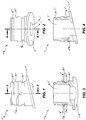
- connection fitting 10 designates generally a connection fitting according to a preferred embodiment of the invention.
- the preferred embodiment is adopted for connecting a plumbing piece such as, in the present instance, a valve to a pump. in the drawings not all integers of the valve are shown.
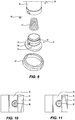
- Connection fitting 10 is provided at its proximal end with a pump connection face 12, said pump connection face 12 being oriented at angle to the longitudinal axis 14 of the bore 16 of the tubular body 18 forming the major part of the connection fitting 10.
- a circumferential groove 20 is provided adjacent the distal end of tubular body 18 to receive an O-ring 19 to provide sealing between the connection fitting and the internal surface 28 of the bore 40 of a valve 30.
- pump connection face 12 of the connection fitting 10 is coupled to a pump inlet or outlet by means of a pump connection nut 22.
- a circumferential channel 24 extends round the outside of the connection fitting and a plurality of recesses 26 extends distally, i.e., in the direction toward the valve, therefrom.
- the plurality of recesses 26, here two in number, are spaced evenly around the circumference of the outside of the tubular body 18.
- a screw 32 with a security head extends inwardly of the longitudinal axis of the bore of the valve and the end 38 of its shaft 34 is received within a recess 26 connected to circumferential channel 24.
- the screw shaft 34 is not inserted so far into the circumferential channel 24 or recess 26 so as to have end 38 thereof engage either the inner surface 36 of the circumferential channel 24 or the inner surface 36' of the recess 26.
- the screw shaft 34 does extend sufficiently far into the circumferential channel 24 or recess 26 as to prevent ejection (by the biasing means) or removal of the connection fitting 10 from the bore 40 of the valve 30. This ensures that the internal components in the valve 30 are retained within bore 40.
- a biasing means within the bore of the valve 30 is provided by compression spring 42 which here is positioned between the proximal end of a thermostatic element 44 and a shoulder 46 within the bore 16 of connection fitting 10.
- Locking screw 48 is provided with a conventional head such as a Phillips head.
- the shaft 50 of locking screw 48 extends into the circumferential channel 24 and/or recess 26. In a locked orientation (not shown here) the end of shaft 50 engages the inner surface 36' of a recess 26 and prevents movement of the connection fitting 10 with respect to the valve 30. Locking screw 48 can be loosened by unscrewing.
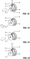
- connection fitting 10 is pushed into bore 40 of the valve 30 or manifold against the face of the compression spring 42.
- the shafts 34 and 50 of the screws then move out of the recesses 26 and into the space defined by circumferential channel 24.
- the connection fitting 10 can be rotated about its longitudinal axis 14 with the ends of screw shafts 38 and 50 being able to be moved along the circumferential channel 24.
- the connection fitting 10 can be released and the compression spring 42 will force it outwardly of the bore 40 of the valve 30.
- connection fitting 10 and pipe connection face 12 can enter the recesses, albeit with the connection fitting 10 and pipe connection face 12 in a new orientation with respect to the valve 30.
- Locking screw 48 can then be screwed in to engage inner surface 36' of recess 26 and lock the connection fitting in place.
Landscapes
- Engineering & Computer Science (AREA)
- General Engineering & Computer Science (AREA)
- Mechanical Engineering (AREA)
- Details Of Reciprocating Pumps (AREA)
Claims (14)
- Verbindungsstück (10) zur Verwendung in Verbindung mit einer Mehrzahl von Installationsteilen, welche Rohre, Schläuche, Ventile, Verteiler oder dergleichen sind, wobei das Verbindungsstück (10) umfasst:einen schlauchförmigen Körper (18), welcher aufweist:ein erstes Ende, welches mit Mitteln zur Verbindung mit einem ersten Installationsteil bereitgestellt ist; undein zweites Ende, welches in eine Bohrung eines zweiten Installationsteils einsetzbar ist oder innerhalb davon aufnehmbar ist,wobei der schlauchförmige Körper (18) einen umlaufenden Kanal (24) und eine Mehrzahl von Ausnehmungen (26) aufweist, welche in dem umlaufenden Kanal (24) münden und in regelmäßigen Abständen um den umlaufenden Kanal (24) beabstandet sind, wobei der umlaufende Kanal (24) und die Ausnehmungen (26) dazu in der Lage sind, derart mit Haltemitteln zusammenzuwirken, dass ein Eingriff zwischen den Haltemitteln und der Mehrzahl von Ausnehmungen (26) das Verbindungsstück (10) in einer aus einer Anzahl vorbestimmter Ausrichtungen an Ort und Stelle ausrichtet.
- Verbindungsstück (10) nach Anspruch 1, wobei die Mittel zur Verbindung mit dem ersten Installationsteil an dem ersten Ende des schlauchförmigen Körpers (18) in einem Winkel zu der longitudinalen Achse des schlauchförmigen Körpers (18) ausgerichtet sind.
- Verbindungsstück (10) nach Anspruch 1 oder 2, wobei das Mittel zur Verbindung an dem ersten Ende des schlauchförmigen Körpers (18) eine ringförmige Platte ist, welche an einem Auslass- oder Einlassverteiler einer Pumpe anliegen kann und welche durch eine mit dem Auslass- oder Einlassverteiler zusammenwirkende Mutter daran gesichert sein kann.
- Verbindungsstück (10) nach einem der Ansprüche 1 bis 3, wobei benachbart zu einem distalen Ende des schlauchförmigen Körpers (18) eine umlaufende Nut (20) zum Aufnehmen eines O-Rings (19) bereitgestellt ist, um eine Dichtung zwischen dem Verbindungsstück (10) und einer Innenfläche (28) einer Bohrung (40) eines Ventils (30) bereitzustellen.
- Verbindungsstück (10) nach einem der Ansprüche 1 bis 4, wobei innerhalb einer Bohrung (40) des schlauchförmigen Körpers (18) des Verbindungsstücks (10) eine Schulter (46) gebildet ist.
- Installationsmechanismus, umfassend:ein Verbindungsstück (10) nach einem der Ansprüche 1 bis 5;das zweite Installationsteil; unddie Haltemittel.
- Installationsmechanismus nach Anspruch 6, wobei ein Vorspannmittel (42) einem Einsetzen des Verbindungsstücks (10) in das zweite Installationsteil entgegenwirkt.
- Installationsmechanismus nach Anspruch 7, wobei das Vorspannmittel (42) ein Zurückführen wenigstens einer der Mehrzahl von Ausnehmungen (26) unterstützt, um mit den Haltemitteln in Eingriff zu treten, um das Verbindungsstück (10) an Ort und Stelle zu verriegeln.
- Installationsmechanismus nach Anspruch 7 oder 8, wobei das Vorspannmittel eine Druckfeder (42) umfasst, welche innerhalb der Bohrung des zweiten Installationsteils gehalten ist;
und wobei optional die Druckfeder (42) an der Schulter innerhalb der Bohrung (16) des schlauchförmigen Körpers (10) aufgenommen ist. - Installationsmechanismus nach einem der Ansprüche 6 bis 9, wobei die Haltemittel an dem zweiten Installationsteil bereitgestellt sind und eine Mehrzahl von Vorsprüngen umfassen.
- Installationsmechanismus nach Anspruch 10, wobei wenigstens einige der Mehrzahl von Vorsprüngen einstellbar sind und durch die Schäfte von Schrauben (32, 48) gebildet sind, welche sich in die Bohrung des zweiten Installationsteils und in den umlaufenden Kanal (24) und/oder die Ausnehmungen (26) des schlauchförmigen Körpers (10) erstrecken.
- Installationsmechanismus nach Anspruch 11, wobei die Schrauben (32, 48) ein- oder herausgeschraubt werden, um das Zusammenwirken der Schäfte der Schrauben (32, 48) mit dem umlaufenden Kanal (24) und/oder den Ausnehmungen (26) zu verstärken oder abzuschwächen, um zu verhindern bzw. zu ermöglichen, dass sich das Verbindungsstück (10) in Bezug auf das Installationsteil bewegt.
- Installationsmechanismus nach einem der Ansprüche 6 bis 12, wobei das zweite Installationsteil ein Ventil ist.
- Installationsmechanismus nach einem der Ansprüche 6 bis 13, ferner umfassend das erste Installationsteil, welches ein Rohr, ein Schlauch oder ein Verteiler ist.
Applications Claiming Priority (2)
| Application Number | Priority Date | Filing Date | Title |
|---|---|---|---|
| AU2014902259A AU2014902259A0 (en) | 2014-06-13 | Adjustable Connection Fitting | |
| PCT/AU2015/050322 WO2015188232A1 (en) | 2014-06-13 | 2015-06-12 | Adjustable connection fitting |
Publications (3)
| Publication Number | Publication Date |
|---|---|
| EP3155306A1 EP3155306A1 (de) | 2017-04-19 |
| EP3155306A4 EP3155306A4 (de) | 2018-02-07 |
| EP3155306B1 true EP3155306B1 (de) | 2020-09-02 |
Family
ID=54832628
Family Applications (1)
| Application Number | Title | Priority Date | Filing Date |
|---|---|---|---|
| EP15806286.9A Not-in-force EP3155306B1 (de) | 2014-06-13 | 2015-06-12 | Anpassbares verbindungsteil |
Country Status (2)
| Country | Link |
|---|---|
| EP (1) | EP3155306B1 (de) |
| WO (1) | WO2015188232A1 (de) |
Family Cites Families (11)
| Publication number | Priority date | Publication date | Assignee | Title |
|---|---|---|---|---|
| GB191410530A (en) * | 1914-04-28 | 1915-04-22 | Jacob William Fennel | Improvements in Hose or Pipe Couplings. |
| GB809085A (en) * | 1956-06-15 | 1959-02-18 | Gas Council | Improvements in or relating to plug type connector sleeves for gas appliances |
| US3345087A (en) * | 1964-06-18 | 1967-10-03 | Ventura Company | Conduit connectors |
| US4124231A (en) * | 1977-05-04 | 1978-11-07 | Vetco, Inc. | Rigid pipe connector with radially shiftable lock elements and method of making the same |
| GB2093547B (en) * | 1981-01-29 | 1984-03-28 | Brookes George | Pipe connector |
| US5004013A (en) * | 1988-04-11 | 1991-04-02 | Great Plains Industries, Inc. | Dripless coupling device |
| US6447028B1 (en) * | 2000-08-18 | 2002-09-10 | Asco Controls, L.P. | Joint fitting |
| US6572154B1 (en) * | 2002-01-08 | 2003-06-03 | Albin J. Niemiec | Threadless flared tube fitting for connecting flow conductors |
| ATE502244T1 (de) * | 2005-05-19 | 2011-04-15 | Floplast Ltd | Rohrverbindung mit verstellbarem winkel |
| IL183868A (en) * | 2007-06-12 | 2011-08-31 | Eliezer Krausz | Multi-angle joint |
| GB0803299D0 (en) * | 2008-02-23 | 2008-04-02 | Pipe Join Technology Ltd | Coupling |
-
2015
- 2015-06-12 WO PCT/AU2015/050322 patent/WO2015188232A1/en not_active Ceased
- 2015-06-12 EP EP15806286.9A patent/EP3155306B1/de not_active Not-in-force
Non-Patent Citations (1)
| Title |
|---|
| None * |
Also Published As
| Publication number | Publication date |
|---|---|
| EP3155306A1 (de) | 2017-04-19 |
| EP3155306A4 (de) | 2018-02-07 |
| WO2015188232A1 (en) | 2015-12-17 |
Similar Documents
| Publication | Publication Date | Title |
|---|---|---|
| EP2627938B1 (de) | Schnell einrastendes leitungsendstück mit hülse | |
| TWI655389B (zh) | Resin pipe joint | |
| US9500307B2 (en) | Slip-on coupling gasket | |
| US8789853B2 (en) | Mechanical pipe fitting device assembly | |
| US9909701B2 (en) | Tube couplings | |
| JP6240455B2 (ja) | 合成樹脂製管継手 | |
| US8608210B2 (en) | Coupling device for tubular members | |
| US20170074433A1 (en) | Coupling gasket with multiple sealing surfaces | |
| US7758085B2 (en) | Tube couplings | |
| CN107588256B (zh) | 塑料密封配件 | |
| CN103807542A (zh) | 快速连接器接头 | |
| CN105179837B (zh) | 用于运送气体、压缩空气、和其他流体的导管的连接接头 | |
| US20220090718A1 (en) | Connector assemblies for connecting tubulars and related methods | |
| WO2010078549A4 (en) | Push-twist connector | |
| US20120217743A1 (en) | Pipe coupling assembly with sleeve locking tabs and associated methods | |
| US12085198B2 (en) | Tight-seal piping component | |
| KR100990296B1 (ko) | 직선형 나사 조절가능한 포트 단부 | |
| US20110148101A1 (en) | Coupling | |
| WO2012064725A2 (en) | Pipe coupling | |
| EP3152473B1 (de) | Verbinder | |
| EP3155306B1 (de) | Anpassbares verbindungsteil | |
| US8668230B2 (en) | Apparatus and methods for splicing conduits and hoses subsea | |
| EP3096059A1 (de) | Drehkupplung | |
| EP3587887B1 (de) | Hochdruckverbundrohr und rohrverbindung | |
| US9777874B2 (en) | Rotary coupling |
Legal Events
| Date | Code | Title | Description |
|---|---|---|---|
| STAA | Information on the status of an ep patent application or granted ep patent |
Free format text: STATUS: THE INTERNATIONAL PUBLICATION HAS BEEN MADE |
|
| PUAI | Public reference made under article 153(3) epc to a published international application that has entered the european phase |
Free format text: ORIGINAL CODE: 0009012 |
|
| STAA | Information on the status of an ep patent application or granted ep patent |
Free format text: STATUS: REQUEST FOR EXAMINATION WAS MADE |
|
| 17P | Request for examination filed |
Effective date: 20161212 |
|
| AK | Designated contracting states |
Kind code of ref document: A1 Designated state(s): AL AT BE BG CH CY CZ DE DK EE ES FI FR GB GR HR HU IE IS IT LI LT LU LV MC MK MT NL NO PL PT RO RS SE SI SK SM TR |
|
| AX | Request for extension of the european patent |
Extension state: BA ME |
|
| DAV | Request for validation of the european patent (deleted) | ||
| DAX | Request for extension of the european patent (deleted) | ||
| A4 | Supplementary search report drawn up and despatched |
Effective date: 20180108 |
|
| RIC1 | Information provided on ipc code assigned before grant |
Ipc: F16L 25/08 20060101ALI20180102BHEP Ipc: F16L 37/248 20060101ALI20180102BHEP Ipc: F16L 27/08 20060101AFI20180102BHEP Ipc: F16L 21/08 20060101ALI20180102BHEP |
|
| STAA | Information on the status of an ep patent application or granted ep patent |
Free format text: STATUS: EXAMINATION IS IN PROGRESS |
|
| 17Q | First examination report despatched |
Effective date: 20190801 |
|
| GRAP | Despatch of communication of intention to grant a patent |
Free format text: ORIGINAL CODE: EPIDOSNIGR1 |
|
| STAA | Information on the status of an ep patent application or granted ep patent |
Free format text: STATUS: GRANT OF PATENT IS INTENDED |
|
| INTG | Intention to grant announced |
Effective date: 20200323 |
|
| GRAS | Grant fee paid |
Free format text: ORIGINAL CODE: EPIDOSNIGR3 |
|
| GRAA | (expected) grant |
Free format text: ORIGINAL CODE: 0009210 |
|
| STAA | Information on the status of an ep patent application or granted ep patent |
Free format text: STATUS: THE PATENT HAS BEEN GRANTED |
|
| AK | Designated contracting states |
Kind code of ref document: B1 Designated state(s): AL AT BE BG CH CY CZ DE DK EE ES FI FR GB GR HR HU IE IS IT LI LT LU LV MC MK MT NL NO PL PT RO RS SE SI SK SM TR |
|
| REG | Reference to a national code |
Ref country code: GB Ref legal event code: FG4D |
|
| REG | Reference to a national code |
Ref country code: AT Ref legal event code: REF Ref document number: 1309217 Country of ref document: AT Kind code of ref document: T Effective date: 20200915 Ref country code: CH Ref legal event code: EP |
|
| REG | Reference to a national code |
Ref country code: DE Ref legal event code: R096 Ref document number: 602015058491 Country of ref document: DE |
|
| REG | Reference to a national code |
Ref country code: IE Ref legal event code: FG4D |
|
| REG | Reference to a national code |
Ref country code: LT Ref legal event code: MG4D |
|
| PG25 | Lapsed in a contracting state [announced via postgrant information from national office to epo] |
Ref country code: LT Free format text: LAPSE BECAUSE OF FAILURE TO SUBMIT A TRANSLATION OF THE DESCRIPTION OR TO PAY THE FEE WITHIN THE PRESCRIBED TIME-LIMIT Effective date: 20200902 Ref country code: HR Free format text: LAPSE BECAUSE OF FAILURE TO SUBMIT A TRANSLATION OF THE DESCRIPTION OR TO PAY THE FEE WITHIN THE PRESCRIBED TIME-LIMIT Effective date: 20200902 Ref country code: FI Free format text: LAPSE BECAUSE OF FAILURE TO SUBMIT A TRANSLATION OF THE DESCRIPTION OR TO PAY THE FEE WITHIN THE PRESCRIBED TIME-LIMIT Effective date: 20200902 Ref country code: BG Free format text: LAPSE BECAUSE OF FAILURE TO SUBMIT A TRANSLATION OF THE DESCRIPTION OR TO PAY THE FEE WITHIN THE PRESCRIBED TIME-LIMIT Effective date: 20201202 Ref country code: NO Free format text: LAPSE BECAUSE OF FAILURE TO SUBMIT A TRANSLATION OF THE DESCRIPTION OR TO PAY THE FEE WITHIN THE PRESCRIBED TIME-LIMIT Effective date: 20201202 Ref country code: GR Free format text: LAPSE BECAUSE OF FAILURE TO SUBMIT A TRANSLATION OF THE DESCRIPTION OR TO PAY THE FEE WITHIN THE PRESCRIBED TIME-LIMIT Effective date: 20201203 Ref country code: SE Free format text: LAPSE BECAUSE OF FAILURE TO SUBMIT A TRANSLATION OF THE DESCRIPTION OR TO PAY THE FEE WITHIN THE PRESCRIBED TIME-LIMIT Effective date: 20200902 |
|
| REG | Reference to a national code |
Ref country code: NL Ref legal event code: MP Effective date: 20200902 |
|
| REG | Reference to a national code |
Ref country code: AT Ref legal event code: MK05 Ref document number: 1309217 Country of ref document: AT Kind code of ref document: T Effective date: 20200902 |
|
| PG25 | Lapsed in a contracting state [announced via postgrant information from national office to epo] |
Ref country code: PL Free format text: LAPSE BECAUSE OF FAILURE TO SUBMIT A TRANSLATION OF THE DESCRIPTION OR TO PAY THE FEE WITHIN THE PRESCRIBED TIME-LIMIT Effective date: 20200902 Ref country code: RS Free format text: LAPSE BECAUSE OF FAILURE TO SUBMIT A TRANSLATION OF THE DESCRIPTION OR TO PAY THE FEE WITHIN THE PRESCRIBED TIME-LIMIT Effective date: 20200902 Ref country code: LV Free format text: LAPSE BECAUSE OF FAILURE TO SUBMIT A TRANSLATION OF THE DESCRIPTION OR TO PAY THE FEE WITHIN THE PRESCRIBED TIME-LIMIT Effective date: 20200902 |
|
| PG25 | Lapsed in a contracting state [announced via postgrant information from national office to epo] |
Ref country code: EE Free format text: LAPSE BECAUSE OF FAILURE TO SUBMIT A TRANSLATION OF THE DESCRIPTION OR TO PAY THE FEE WITHIN THE PRESCRIBED TIME-LIMIT Effective date: 20200902 Ref country code: PT Free format text: LAPSE BECAUSE OF FAILURE TO SUBMIT A TRANSLATION OF THE DESCRIPTION OR TO PAY THE FEE WITHIN THE PRESCRIBED TIME-LIMIT Effective date: 20210104 Ref country code: SM Free format text: LAPSE BECAUSE OF FAILURE TO SUBMIT A TRANSLATION OF THE DESCRIPTION OR TO PAY THE FEE WITHIN THE PRESCRIBED TIME-LIMIT Effective date: 20200902 Ref country code: RO Free format text: LAPSE BECAUSE OF FAILURE TO SUBMIT A TRANSLATION OF THE DESCRIPTION OR TO PAY THE FEE WITHIN THE PRESCRIBED TIME-LIMIT Effective date: 20200902 Ref country code: NL Free format text: LAPSE BECAUSE OF FAILURE TO SUBMIT A TRANSLATION OF THE DESCRIPTION OR TO PAY THE FEE WITHIN THE PRESCRIBED TIME-LIMIT Effective date: 20200902 Ref country code: CZ Free format text: LAPSE BECAUSE OF FAILURE TO SUBMIT A TRANSLATION OF THE DESCRIPTION OR TO PAY THE FEE WITHIN THE PRESCRIBED TIME-LIMIT Effective date: 20200902 |
|
| PG25 | Lapsed in a contracting state [announced via postgrant information from national office to epo] |
Ref country code: AL Free format text: LAPSE BECAUSE OF FAILURE TO SUBMIT A TRANSLATION OF THE DESCRIPTION OR TO PAY THE FEE WITHIN THE PRESCRIBED TIME-LIMIT Effective date: 20200902 Ref country code: AT Free format text: LAPSE BECAUSE OF FAILURE TO SUBMIT A TRANSLATION OF THE DESCRIPTION OR TO PAY THE FEE WITHIN THE PRESCRIBED TIME-LIMIT Effective date: 20200902 Ref country code: ES Free format text: LAPSE BECAUSE OF FAILURE TO SUBMIT A TRANSLATION OF THE DESCRIPTION OR TO PAY THE FEE WITHIN THE PRESCRIBED TIME-LIMIT Effective date: 20200902 Ref country code: IS Free format text: LAPSE BECAUSE OF FAILURE TO SUBMIT A TRANSLATION OF THE DESCRIPTION OR TO PAY THE FEE WITHIN THE PRESCRIBED TIME-LIMIT Effective date: 20210102 |
|
| REG | Reference to a national code |
Ref country code: DE Ref legal event code: R097 Ref document number: 602015058491 Country of ref document: DE |
|
| PG25 | Lapsed in a contracting state [announced via postgrant information from national office to epo] |
Ref country code: SK Free format text: LAPSE BECAUSE OF FAILURE TO SUBMIT A TRANSLATION OF THE DESCRIPTION OR TO PAY THE FEE WITHIN THE PRESCRIBED TIME-LIMIT Effective date: 20200902 |
|
| PLBE | No opposition filed within time limit |
Free format text: ORIGINAL CODE: 0009261 |
|
| STAA | Information on the status of an ep patent application or granted ep patent |
Free format text: STATUS: NO OPPOSITION FILED WITHIN TIME LIMIT |
|
| 26N | No opposition filed |
Effective date: 20210603 |
|
| PG25 | Lapsed in a contracting state [announced via postgrant information from national office to epo] |
Ref country code: SI Free format text: LAPSE BECAUSE OF FAILURE TO SUBMIT A TRANSLATION OF THE DESCRIPTION OR TO PAY THE FEE WITHIN THE PRESCRIBED TIME-LIMIT Effective date: 20200902 Ref country code: DK Free format text: LAPSE BECAUSE OF FAILURE TO SUBMIT A TRANSLATION OF THE DESCRIPTION OR TO PAY THE FEE WITHIN THE PRESCRIBED TIME-LIMIT Effective date: 20200902 |
|
| PG25 | Lapsed in a contracting state [announced via postgrant information from national office to epo] |
Ref country code: IT Free format text: LAPSE BECAUSE OF FAILURE TO SUBMIT A TRANSLATION OF THE DESCRIPTION OR TO PAY THE FEE WITHIN THE PRESCRIBED TIME-LIMIT Effective date: 20200902 |
|
| REG | Reference to a national code |
Ref country code: DE Ref legal event code: R119 Ref document number: 602015058491 Country of ref document: DE |
|
| PG25 | Lapsed in a contracting state [announced via postgrant information from national office to epo] |
Ref country code: MC Free format text: LAPSE BECAUSE OF FAILURE TO SUBMIT A TRANSLATION OF THE DESCRIPTION OR TO PAY THE FEE WITHIN THE PRESCRIBED TIME-LIMIT Effective date: 20200902 |
|
| REG | Reference to a national code |
Ref country code: CH Ref legal event code: PL |
|
| REG | Reference to a national code |
Ref country code: BE Ref legal event code: MM Effective date: 20210630 |
|
| PG25 | Lapsed in a contracting state [announced via postgrant information from national office to epo] |
Ref country code: LU Free format text: LAPSE BECAUSE OF NON-PAYMENT OF DUE FEES Effective date: 20210612 |
|
| PG25 | Lapsed in a contracting state [announced via postgrant information from national office to epo] |
Ref country code: LI Free format text: LAPSE BECAUSE OF NON-PAYMENT OF DUE FEES Effective date: 20210630 Ref country code: DE Free format text: LAPSE BECAUSE OF NON-PAYMENT OF DUE FEES Effective date: 20220101 Ref country code: CH Free format text: LAPSE BECAUSE OF NON-PAYMENT OF DUE FEES Effective date: 20210630 |
|
| PG25 | Lapsed in a contracting state [announced via postgrant information from national office to epo] |
Ref country code: FR Free format text: LAPSE BECAUSE OF NON-PAYMENT OF DUE FEES Effective date: 20210630 |
|
| PG25 | Lapsed in a contracting state [announced via postgrant information from national office to epo] |
Ref country code: BE Free format text: LAPSE BECAUSE OF NON-PAYMENT OF DUE FEES Effective date: 20210630 |
|
| PG25 | Lapsed in a contracting state [announced via postgrant information from national office to epo] |
Ref country code: HU Free format text: LAPSE BECAUSE OF FAILURE TO SUBMIT A TRANSLATION OF THE DESCRIPTION OR TO PAY THE FEE WITHIN THE PRESCRIBED TIME-LIMIT; INVALID AB INITIO Effective date: 20150612 |
|
| PG25 | Lapsed in a contracting state [announced via postgrant information from national office to epo] |
Ref country code: CY Free format text: LAPSE BECAUSE OF FAILURE TO SUBMIT A TRANSLATION OF THE DESCRIPTION OR TO PAY THE FEE WITHIN THE PRESCRIBED TIME-LIMIT Effective date: 20200902 |
|
| PGFP | Annual fee paid to national office [announced via postgrant information from national office to epo] |
Ref country code: IE Payment date: 20230627 Year of fee payment: 9 |
|
| P01 | Opt-out of the competence of the unified patent court (upc) registered |
Effective date: 20230626 |
|
| PGFP | Annual fee paid to national office [announced via postgrant information from national office to epo] |
Ref country code: GB Payment date: 20230627 Year of fee payment: 9 |
|
| PG25 | Lapsed in a contracting state [announced via postgrant information from national office to epo] |
Ref country code: MK Free format text: LAPSE BECAUSE OF FAILURE TO SUBMIT A TRANSLATION OF THE DESCRIPTION OR TO PAY THE FEE WITHIN THE PRESCRIBED TIME-LIMIT Effective date: 20200902 |
|
| PG25 | Lapsed in a contracting state [announced via postgrant information from national office to epo] |
Ref country code: TR Free format text: LAPSE BECAUSE OF FAILURE TO SUBMIT A TRANSLATION OF THE DESCRIPTION OR TO PAY THE FEE WITHIN THE PRESCRIBED TIME-LIMIT Effective date: 20200902 |
|
| PG25 | Lapsed in a contracting state [announced via postgrant information from national office to epo] |
Ref country code: MT Free format text: LAPSE BECAUSE OF FAILURE TO SUBMIT A TRANSLATION OF THE DESCRIPTION OR TO PAY THE FEE WITHIN THE PRESCRIBED TIME-LIMIT Effective date: 20200902 |
|
| GBPC | Gb: european patent ceased through non-payment of renewal fee |
Effective date: 20240612 |
|
| PG25 | Lapsed in a contracting state [announced via postgrant information from national office to epo] |
Ref country code: IE Free format text: LAPSE BECAUSE OF NON-PAYMENT OF DUE FEES Effective date: 20240612 |
|
| PG25 | Lapsed in a contracting state [announced via postgrant information from national office to epo] |
Ref country code: GB Free format text: LAPSE BECAUSE OF NON-PAYMENT OF DUE FEES Effective date: 20240612 |