EP3155337B1 - Kältegerät mit herausziehbarem gemüseaufbewahrungsbehälter - Google Patents
Kältegerät mit herausziehbarem gemüseaufbewahrungsbehälter Download PDFInfo
- Publication number
- EP3155337B1 EP3155337B1 EP14729892.1A EP14729892A EP3155337B1 EP 3155337 B1 EP3155337 B1 EP 3155337B1 EP 14729892 A EP14729892 A EP 14729892A EP 3155337 B1 EP3155337 B1 EP 3155337B1
- Authority
- EP
- European Patent Office
- Prior art keywords
- receiving device
- refrigeration appliance
- railing
- refrigeration
- connection
- Prior art date
- Legal status (The legal status is an assumption and is not a legal conclusion. Google has not performed a legal analysis and makes no representation as to the accuracy of the status listed.)
- Active
Links
Images




Classifications
-
- F—MECHANICAL ENGINEERING; LIGHTING; HEATING; WEAPONS; BLASTING
- F25—REFRIGERATION OR COOLING; COMBINED HEATING AND REFRIGERATION SYSTEMS; HEAT PUMP SYSTEMS; MANUFACTURE OR STORAGE OF ICE; LIQUEFACTION SOLIDIFICATION OF GASES
- F25D—REFRIGERATORS; COLD ROOMS; ICE-BOXES; COOLING OR FREEZING APPARATUS NOT OTHERWISE PROVIDED FOR
- F25D25/00—Charging, supporting, and discharging the articles to be cooled
- F25D25/02—Charging, supporting, and discharging the articles to be cooled by shelves
- F25D25/024—Slidable shelves
- F25D25/025—Drawers
-
- F—MECHANICAL ENGINEERING; LIGHTING; HEATING; WEAPONS; BLASTING
- F25—REFRIGERATION OR COOLING; COMBINED HEATING AND REFRIGERATION SYSTEMS; HEAT PUMP SYSTEMS; MANUFACTURE OR STORAGE OF ICE; LIQUEFACTION SOLIDIFICATION OF GASES
- F25D—REFRIGERATORS; COLD ROOMS; ICE-BOXES; COOLING OR FREEZING APPARATUS NOT OTHERWISE PROVIDED FOR
- F25D23/00—General constructional features
- F25D23/06—Walls
- F25D23/065—Details
- F25D23/067—Supporting elements
Definitions
- the present invention relates to a household appliance and more particularly a refrigeration appliance having a container in the form of an extractable unit operated in the inner compartment of the appliance.
- a refrigeration appliance has a plurality of shelves and containers for preserving food items.
- a withdrawable container may typically be arranged in the manner that its base extends in parallel with the base of the appliance so as to be movable out of the internal space of the appliance in order for allowing users to reach stored food items therein.
- a special extractable container generally designated as a vegetable or fruit storage container can store and carry as much as 30 kg of fruit and vegetables.
- Two railing devices are generally laterally disposed to provide guiding and carry the container while it is moved back and forth.
- a railing device's connection with the inner compartment walls of the refrigeration appliance can be made by various connection elements, which may substantially affect production efficiency of the refrigeration appliance as a large number of individual connection elements can be necessary for a single container, let alone a higher-end refrigeration appliance with a plurality of such containers.
- connection elements may also significantly contribute to the overall costs in a mass-produced appliance.
- a prior art publication in the technical field of the present invention may be referred to as DE102010039625 A1 among others, the document disclosing a refrigerator including an extractable container, and a conveying unit formed in an inner space of a vertical wall of the extractable container.
- the conveying unit includes a guide part to guide the movement of a partition member that divides a storage space of the extractable container, and a fixing part to restrict the movement of the partition member.
- Refrigeration appliances with railing devices using snap-fit connections to be mounted into the inner walls of the refrigeration cabin are known from documents EP 2 662 649 A2 and EP 2 662 650 A2 .
- the present invention provides a refrigeration appliance having at least one extractable container traveling in engagement with two railing devices mounted on inner lateral walls of the refrigeration cabin as defined by the characterizing features as defined in Claim 1.
- Primary object of the present invention is hence to provide a refrigeration appliance with an extractable storage container movable on lateral railing devices, such devices being fixedly secured on lateral receiving devices without requiring any connection elements.
- the present invention proposes a refrigeration appliance with at least one extractable storage container guidably movable into the refrigeration appliance traveling on railing devices on both sides at the lateral walls.
- Said railing devices are fixedly attached to respective receiving devices of the lateral walls to support and carry the railing devices in a fixed manner.
- a railing device may have two types of connection members, namely a grappling member and a fixation rod, both having engagement ends engaging with respective slots of the receiving device in different directions and forming therewith different engagement surfaces and connection directions.
- the first and second connection directions along which reciprocal engagement surfaces or contact surfaces are created are perpendicular to each other.
- a peripheral frame flange of the railing device has a flange skirt portion leaning against lateral wall portions of the refrigeration cabin where said receiving device is enclosed, thereby helping secure the railing device on the receiving device. Further, an inward skirt portion of said peripheral frame flange fits into a receiving device channel, serving to the same purpose as the flange skirt portion does.
- fixation rods protruding out from the railing device along the upper and lower longitudinal sides of the peripheral frame flange are structurally different in that while the upper fixation rods are integrally formed at the sides with a frame edge portion of the railing device, the lower ones have lateral fixation rod recesses on the inward skirt portion.
- a rib-like structure may be provided to mechanically support the receiving devices such that they can maintain their shape against polyurethane material deformation.
- the receiving devices comprise a series of surface formations in the form semi-columns and protrusions extending in parallel in vertical manner.
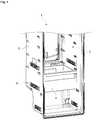
- the present invention relates to a household appliance and more particularly a refrigeration appliance (1) having an interior refrigeration cabin (2) enclosed by a heat-insulating housing and at least one storage container (4) for storing food items in a refrigerated manner.
- the refrigeration appliance (1) may typically have a main body with a multitude of storage chambers and doors opening and closing a front side of the main body.
- a refrigerating cabin (2) as well as a freezing cabin may be disposed so as to provide separate divisions within the inside of the main body.
- the refrigerating cabin (2) of the invention may comprise a plurality of shelves and comprises at least one withdrawable storage container (4) generally designated as a storage space for food items such as vegetables and fruits.
- the refrigeration appliance (1) may conventionally have a certain number of storage containers (4), each one communicating with railing device (5) mechanisms at lateral sides. Said railing devices (5), which are in turn secured on receiving devices (6) embedded in the lateral walls (3) of the refrigeration cabin (2), effect guiding and carrying of the storage containers (4) into and out of the inside of the refrigeration cabin (2).
- the receiving devices (6) can alternatively be provided as an integrally shaped part of the lateral walls (3) of the refrigeration cabin (2).
- the railing device (5) of the invention may comprise a grappling member (7) establishing an engagement-type connection with a grappling member slot (8) of the receiving device (6) by means of a grappling member engagement end (9).
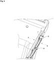
- the inter-engaging relationship of the two is shown in Fig. 4 , where a longitudinal cross-sectional perspective view of the railing device (5) in engagement with the receiving device (6) is presented.
- fixation rods (10) oriented in a perpendicular direction from the railing device (5) extending in the direction of the receiving device (6) fit in fixation rod slots (11) of the receiving device (6) such that fixation rod engagement ends (12) are urged into engaged relation with said fixation rod slots (11).
- the mechanical connection between the railing device (5) and the receiving device (6) is securely established without requiring any connection elements such as screws, nuts, rivets, pins, threaded couplings and the like, which substantially contributes to the manufacturing efficiency of the refrigeration appliance (1) because mounting of a substantial number of connection elements is avoided and manufacturing costs are decreased through reduction of such components and man-hours accordingly.
- a peripheral frame flange's (14) flange skirt portions (15) press against the lateral wall (3) enclosing the receiving device (6) so as to help retain the railing device (5) in fixed position. Further, an inward skirt portion (16) is fitted in a receiving device channel (17), whereby the receiving device's (5) vertical displacement is prevented.
- the fixation rods (10) while the upper fixation rods (10) are integrally connected with a frame edge (18) portion of the railing device (5) at two sides, the lower fixation rods (10) extending out from the railing device's (5) internal side in the direction of the receiving device (6) are spaced apart from the inward skirt portion (16) by fixation rod recesses (19).
- the fixation rods (10) can also be resiliently deformed to be removed or fitted inside the fixation rod slots (11) thanks to fixation rod flange openings (20) in the peripheral frame flange (14). While removing, the fixation rods (10) can be flexed by using a sharp object such as a screwdriver insertable through said rod flange openings (20).
- a rib-like structure (13) may be arranged on the internal surface of the receiving device (6) to define a series of columns.
- the rib-like structure (13) is effective in overcoming deformation on the surfaces where polyurethane is applied, by providing reinforcement by a plurality of support elements.
- the present invention proposes a refrigeration appliance (1) having an interior refrigeration cabin (2) enclosed by a heat-insulating housing, a door opening and closing a front side of the refrigeration cabin (2) and at least one extractable storage container (4) for storing food items in a refrigerated manner, said extractable storage container (4) mechanically communicating with railing devices (5) at lateral sides and the railing devices (5) being in turn fixedly secured on receiving devices (6) embedded in lateral walls (3) of the refrigeration cabin (2).
- the railing device (5) comprises a plurality of fixation rods (10) having a fixation rod engagement end (12) establishing a snap-fit connection with the receiving device (6).
- the engagement-type snap-fit connection established by flexing respective parts provides a practical yet secure attachment relation obtained without any additional individual intermediate elements.
- the railing device (5) comprises a grappling member (7) with a grappling member engagement end (9) establishing an engagement-type connection with the receiving device (6).
- the fixation rod (10) establishes a snap-fit connection with the receiving device (6) in a first connection direction (D 1 ) and the grappling member (7) establishes an engagement-type connection with the receiving device (6) in a second connection direction (D 2 ).
- first and second connection directions (D 1 , D 2 ) are different from each other and the first and second connection directions (D 1 , D 2 ) are preferably perpendicular to each other. While different connection directions provide a reliable engagement effect with a robust mechanical connection, perpendicular connection directions enhance this effect even further.
- the grappling member (7) establishes an engagement-type connection with a grappling member slot (8) of the receiving device (6).
- the contact surface between the grappling member engagement end (9) and the grappling member slot (8) therefore provides that a second connection direction (D 2 ) is established.
- the railing device (5) comprises a peripheral frame flange (14) with a flange skirt portion (15), the flange skirt portion (15) pressing against lateral wall (3) portions of the refrigeration cabin (2) surrounding the receiving device (6) and the fixation rods (10) establish a snap-fit connection with the receiving device (6) fitting which may be in a fixation rod slot (11) of the receiving device (6).
- the contact surface between the fixation rod engagement end (12) and the fixation rod slot (11) therefore provides that the first connection direction (D 1 ) is established.
- said fixation rods (10) are oriented in a perpendicular direction from the railing device (5), extending in the direction of the receiving device (6).
- an inward skirt portion (16) of said peripheral frame flange (14) is fitted in a receiving device channel (17).
- fixation rods (10) along a first longitudinal side of the peripheral frame flange (14) are integrally connected with a frame edge (18) portion of the railing device (5) at two sides.
- a rib-like structure (13) is arranged on an internal surface of the receiving device (6) to define a series of columns.
- said receiving devices (6) are either embedded in the lateral walls (3) or provided as an integrally shaped part of said lateral walls (3) of the refrigeration cabin (2).
- the present invention provides a refrigeration appliance (1) the extractable storage containers (4) of which travel in engagement with two railing devices (5) being fixedly mounted on lateral receiving devices (6) without requiring any further connection elements.
Landscapes
- Engineering & Computer Science (AREA)
- Chemical & Material Sciences (AREA)
- Combustion & Propulsion (AREA)
- Physics & Mathematics (AREA)
- Mechanical Engineering (AREA)
- Thermal Sciences (AREA)
- General Engineering & Computer Science (AREA)
- Refrigerator Housings (AREA)
Claims (10)
- Ein Kältegerät (1) umfasst mit einer von einem wärmeisolierenden Gehäuse umschlossenen inneren Kühlkabine (2), eine Tür zum Öffnen und Schließen der Vorderseite der Kühlkabine (2) und mindestens eines herausnehmbaren Vorratsbehälter (4) zum gekühlten Aufbewahren von Lebensmitteln, wobei der herausnehmbare Vorratsbehälter (4) seitlich mit Geländervorrichtungen (5) in Verbindung steht und die Geländervorrichtungen (5) an Aufnahmevorrichtungen (6) in Seitenwänden (3) der Kühlkabine (2) mit dem Geländer fest verbunden sind, wobei die Geländervorrichtung (5) einen Umfangsrahmenflansch (14) mit einem Flanschrandabschnitt (15) aufweist, wobei der Flanschrandabschnitt (15) gegen die die Aufnahmevorrichtung (6) umgebenden Seitenwandabschnitte (3) der Kühlkabine (2) drückt; mit einem nach innen gerichteten Randabschnitt (16), der umlaufende Rahmenflansch (14) ist und in einen Aufnahmekanal (17) einpasst, gekennzeichnet ist es dadurch, dass die Geländervorrichtung (5) mehrere Befestigungsstangen (10) mit einem Befestigungsstangen-Eingriffsende (12) aufweist, das eine Schnappverbindung mit der Aufnahmevorrichtung (6) herstellt, wobei Befestigungsstangen (10) entlang einer ersten Längsseite des Rahmenflansches (14) an zwei Seiten einstückig mit einem Rahmenrandabschnitt (18) der Geländervorrichtung (5) ausgebildet sind und die Befestigungsstangen (10) entlang einer zweiten Längsseite des Rahmenflansches (14) durch seitliche Befestigungsstangenausnehmungen (19) vom inneren Randabschnitt (16) beabstandet sind.
- Ein Kältegerät (1), wie in Anspruch 1 aufgeführt, ist dadurch gekennzeichnet, dass die Geländervorrichtung (5) ein Greifelement (7) mit einem Greifelement-Eingriffsende (9) umfasst, dass eine Eingriffsverbindung mit der Aufnahmevorrichtung (6) herstellt.
- Ein Kältegerät (1), wie in Anspruch 1 oder 2 aufgeführt, ist dadurch gekennzeichnet, dass der Befestigungsstab (10) in einer ersten Verbindungsrichtung (D1) eine Schnappverbindung mit der Aufnahmevorrichtung (6) herstellt und das Greifelement (7) eine Eingriffsverbindung mit der Aufnahmevorrichtung (6) in einer zweiten Verbindungsrichtung (D2) herstellt.
- Ein Kältegerät (1), wie in Anspruch 3 aufgeführt, ist dadurch gekennzeichnet, dass die erste und die zweite Verbindungsrichtung (D1, D2) unterschiedlich voneinander sind.
- Ein Kältegerät (1), wie in Anspruch 4 aufgeführt, ist dadurch gekennzeichnet, dass die erste und die zweite Verbindungsrichtung (D1, D2) senkrecht zueinander sind.
- Ein Kältegerät (1), wie in Anspruch 2 aufgeführt, ist dadurch gekennzeichnet, dass das Greifelement (7) eine Eingriffsverbindung mit einem Greifelementschlitz (8) der Aufnahmevorrichtung (6) herstellt.
- Ein Kältegerät (1), wie in Anspruch 1 aufgeführt, ist dadurch gekennzeichnet, dass der Befestigungsstab (10) eine Schnappverbindung mit der Aufnahmeeinrichtung (6) herstellt, die in einen Befestigungsabschlitz (11) der Aufnahmeeinrichtung (6) passt.
- Ein Kältegerät (1), wie in Anspruch 7 aufgeführt, ist dadurch gekennzeichnet, dass die Befestigungsstäbe (10) von der Geländervorrichtung (5) in senkrechter Richtung ausgerichtet sind und sich in Richtung der Aufnahmevorrichtung (6) erstrecken.
- Ein Kältegerät (1), wie in Anspruch 1 aufgeführt, ist dadurch gekennzeichnet, dass eine rippenartige Struktur (13) auf einer Innenfläche der Aufnahmevorrichtung (6) angeordnet ist, um eine Reihe von Säulen darzustellen.
- Ein Kältegerät (1), wie in einem der vorherigen Ansprüchen aufgeführt, ist dadurch gekennzeichnet, dass die Aufnahmevorrichtungen (6) entweder in die Seitenwände (3) eingebettet oder als einstückiger Teil der Seitenwände (3) der Kühlkabine (2) vorgesehen sind.
Priority Applications (1)
| Application Number | Priority Date | Filing Date | Title |
|---|---|---|---|
| PL14729892T PL3155337T3 (pl) | 2014-06-12 | 2014-06-12 | Urządzenie chłodnicze z wyciąganym pojemnikiem do przechowywania warzyw |
Applications Claiming Priority (1)
| Application Number | Priority Date | Filing Date | Title |
|---|---|---|---|
| PCT/EP2014/062175 WO2015188862A1 (en) | 2014-06-12 | 2014-06-12 | Refrigeration appliance with an extractable vegetable storage container |
Publications (2)
| Publication Number | Publication Date |
|---|---|
| EP3155337A1 EP3155337A1 (de) | 2017-04-19 |
| EP3155337B1 true EP3155337B1 (de) | 2019-11-06 |
Family
ID=50942278
Family Applications (1)
| Application Number | Title | Priority Date | Filing Date |
|---|---|---|---|
| EP14729892.1A Active EP3155337B1 (de) | 2014-06-12 | 2014-06-12 | Kältegerät mit herausziehbarem gemüseaufbewahrungsbehälter |
Country Status (3)
| Country | Link |
|---|---|
| EP (1) | EP3155337B1 (de) |
| PL (1) | PL3155337T3 (de) |
| WO (1) | WO2015188862A1 (de) |
Cited By (1)
| Publication number | Priority date | Publication date | Assignee | Title |
|---|---|---|---|---|
| WO2022223293A1 (de) | 2021-04-21 | 2022-10-27 | BSH Hausgeräte GmbH | Haushaltskältegerät mit spezifischer schiene für eine schale, sowie verfahren zur montage der schiene |
Families Citing this family (1)
| Publication number | Priority date | Publication date | Assignee | Title |
|---|---|---|---|---|
| KR20230013479A (ko) * | 2021-07-19 | 2023-01-26 | 삼성전자주식회사 | 냉장고 |
Citations (1)
| Publication number | Priority date | Publication date | Assignee | Title |
|---|---|---|---|---|
| EP1999418A1 (de) * | 2006-03-21 | 2008-12-10 | BSH Bosch und Siemens Hausgeräte GmbH | Bauteil zur montage an einer wand und damit ausgestattetes gerätegehäuse |
Family Cites Families (5)
| Publication number | Priority date | Publication date | Assignee | Title |
|---|---|---|---|---|
| DE102004014464A1 (de) * | 2004-03-24 | 2005-10-13 | Liebherr-Hausgeräte Ochsenhausen GmbH | Befestigungsanordnung und Verfahren zur Befestigung von Elementen an der Innenverkleidung von Kühl- und/oder Gefriergeräten und Verfahren zur Herstellung einer solchen Befestigungsanordnung |
| EP2159523B1 (de) * | 2008-08-29 | 2018-08-01 | Electrolux Home Products Corporation N.V. | Kühlanlage und Konsolensystem zur Verwendung in dieser |
| DE102010039625A1 (de) | 2010-08-20 | 2012-02-23 | BSH Bosch und Siemens Hausgeräte GmbH | Kältegerät und höhenverstellbarer Fachbodenaufbau dafür |
| EP2662650A3 (de) * | 2012-05-08 | 2014-01-22 | Liebherr-Hausgeräte Ochsenhausen GmbH | Kühl- und/oder Gefriergerät |
| DE102012012168A1 (de) * | 2012-05-08 | 2013-11-14 | Liebherr-Hausgeräte Ochsenhausen GmbH | Kühl- und/oder Gefriergerät |
-
2014
- 2014-06-12 WO PCT/EP2014/062175 patent/WO2015188862A1/en not_active Ceased
- 2014-06-12 PL PL14729892T patent/PL3155337T3/pl unknown
- 2014-06-12 EP EP14729892.1A patent/EP3155337B1/de active Active
Patent Citations (1)
| Publication number | Priority date | Publication date | Assignee | Title |
|---|---|---|---|---|
| EP1999418A1 (de) * | 2006-03-21 | 2008-12-10 | BSH Bosch und Siemens Hausgeräte GmbH | Bauteil zur montage an einer wand und damit ausgestattetes gerätegehäuse |
Cited By (2)
| Publication number | Priority date | Publication date | Assignee | Title |
|---|---|---|---|---|
| WO2022223293A1 (de) | 2021-04-21 | 2022-10-27 | BSH Hausgeräte GmbH | Haushaltskältegerät mit spezifischer schiene für eine schale, sowie verfahren zur montage der schiene |
| DE102021203941A1 (de) | 2021-04-21 | 2022-10-27 | BSH Hausgeräte GmbH | Haushaltskältegerät mit spezifischer Schiene für eine Schale, sowie Verfahren zur Montage einer Auflageschiene |
Also Published As
| Publication number | Publication date |
|---|---|
| PL3155337T3 (pl) | 2020-06-01 |
| WO2015188862A1 (en) | 2015-12-17 |
| EP3155337A1 (de) | 2017-04-19 |
Similar Documents
| Publication | Publication Date | Title |
|---|---|---|
| US9677807B2 (en) | Refrigerator | |
| US8905503B2 (en) | Refrigerator appliance with a divider support | |
| US7300121B2 (en) | Shelf for a refrigerating appliance, in particular a bottle shelf for a bottle-storing cooler cabinet | |
| US11073326B2 (en) | Door comprising a door frame and a recessed handle element, and a domestic refrigeration appliance comprising such a door | |
| US10386111B2 (en) | Home appliance device and method for assembling a home appliance device | |
| KR101622008B1 (ko) | 냉장고용 중앙 격벽 밀착구조 및 이를 구비한 냉장고 | |
| KR20130055001A (ko) | 냉장고의 제품 라인의 라이너, 이 형태의 챔버의 진공 성형을 위한 다이 및 방법 | |
| EP3176525A1 (de) | Kühlschrank | |
| KR20150112590A (ko) | 도어 핸들 및 이를 포함하는 냉장고 | |
| KR20100137377A (ko) | 냉장고 | |
| WO2013042338A2 (en) | Refrigerator | |
| EP3155337B1 (de) | Kältegerät mit herausziehbarem gemüseaufbewahrungsbehälter | |
| WO2012045577A2 (de) | Kältegerät mit einem fachboden | |
| KR101738242B1 (ko) | 냉장고의 레일 어셈블리 | |
| RU2661384C1 (ru) | Холодильник | |
| JP6555855B2 (ja) | 冷蔵庫 | |
| EP2357438A1 (de) | Schublade für ein Kältegerät | |
| KR102131054B1 (ko) | 냉장고용 선반지지 어셈블리 | |
| KR20130135643A (ko) | 분리바 어셈블리가 구비된 냉장고 도어구조 및 이를 구비한 냉장고 | |
| WO2016066214A1 (en) | Refrigeration appliance shelf connected with storage container railing device | |
| KR101823395B1 (ko) | 수납 상자 조립체 | |
| KR20140088382A (ko) | 냉장고 선반 조립체 | |
| KR100833323B1 (ko) | 식품 저장고의 프런트패널 조립구조 | |
| EP3149412B1 (de) | Kältevorrichtung mit einer tür-in-tür-struktur | |
| KR100568205B1 (ko) | 냉장고용 선반 포장재 |
Legal Events
| Date | Code | Title | Description |
|---|---|---|---|
| STAA | Information on the status of an ep patent application or granted ep patent |
Free format text: STATUS: THE INTERNATIONAL PUBLICATION HAS BEEN MADE |
|
| PUAI | Public reference made under article 153(3) epc to a published international application that has entered the european phase |
Free format text: ORIGINAL CODE: 0009012 |
|
| STAA | Information on the status of an ep patent application or granted ep patent |
Free format text: STATUS: REQUEST FOR EXAMINATION WAS MADE |
|
| 17P | Request for examination filed |
Effective date: 20161101 |
|
| AK | Designated contracting states |
Kind code of ref document: A1 Designated state(s): AL AT BE BG CH CY CZ DE DK EE ES FI FR GB GR HR HU IE IS IT LI LT LU LV MC MK MT NL NO PL PT RO RS SE SI SK SM TR |
|
| AX | Request for extension of the european patent |
Extension state: BA ME |
|
| DAX | Request for extension of the european patent (deleted) | ||
| RAP1 | Party data changed (applicant data changed or rights of an application transferred) |
Owner name: ARCELIK ANONIM SIRKETI |
|
| GRAP | Despatch of communication of intention to grant a patent |
Free format text: ORIGINAL CODE: EPIDOSNIGR1 |
|
| STAA | Information on the status of an ep patent application or granted ep patent |
Free format text: STATUS: GRANT OF PATENT IS INTENDED |
|
| INTG | Intention to grant announced |
Effective date: 20190726 |
|
| GRAS | Grant fee paid |
Free format text: ORIGINAL CODE: EPIDOSNIGR3 |
|
| GRAA | (expected) grant |
Free format text: ORIGINAL CODE: 0009210 |
|
| STAA | Information on the status of an ep patent application or granted ep patent |
Free format text: STATUS: THE PATENT HAS BEEN GRANTED |
|
| AK | Designated contracting states |
Kind code of ref document: B1 Designated state(s): AL AT BE BG CH CY CZ DE DK EE ES FI FR GB GR HR HU IE IS IT LI LT LU LV MC MK MT NL NO PL PT RO RS SE SI SK SM TR |
|
| REG | Reference to a national code |
Ref country code: GB Ref legal event code: FG4D |
|
| REG | Reference to a national code |
Ref country code: CH Ref legal event code: EP Ref country code: AT Ref legal event code: REF Ref document number: 1199294 Country of ref document: AT Kind code of ref document: T Effective date: 20191115 |
|
| REG | Reference to a national code |
Ref country code: IE Ref legal event code: FG4D |
|
| REG | Reference to a national code |
Ref country code: DE Ref legal event code: R096 Ref document number: 602014056274 Country of ref document: DE |
|
| REG | Reference to a national code |
Ref country code: NL Ref legal event code: MP Effective date: 20191106 |
|
| REG | Reference to a national code |
Ref country code: LT Ref legal event code: MG4D |
|
| PG25 | Lapsed in a contracting state [announced via postgrant information from national office to epo] |
Ref country code: LV Free format text: LAPSE BECAUSE OF FAILURE TO SUBMIT A TRANSLATION OF THE DESCRIPTION OR TO PAY THE FEE WITHIN THE PRESCRIBED TIME-LIMIT Effective date: 20191106 Ref country code: SE Free format text: LAPSE BECAUSE OF FAILURE TO SUBMIT A TRANSLATION OF THE DESCRIPTION OR TO PAY THE FEE WITHIN THE PRESCRIBED TIME-LIMIT Effective date: 20191106 Ref country code: NL Free format text: LAPSE BECAUSE OF FAILURE TO SUBMIT A TRANSLATION OF THE DESCRIPTION OR TO PAY THE FEE WITHIN THE PRESCRIBED TIME-LIMIT Effective date: 20191106 Ref country code: LT Free format text: LAPSE BECAUSE OF FAILURE TO SUBMIT A TRANSLATION OF THE DESCRIPTION OR TO PAY THE FEE WITHIN THE PRESCRIBED TIME-LIMIT Effective date: 20191106 Ref country code: GR Free format text: LAPSE BECAUSE OF FAILURE TO SUBMIT A TRANSLATION OF THE DESCRIPTION OR TO PAY THE FEE WITHIN THE PRESCRIBED TIME-LIMIT Effective date: 20200207 Ref country code: NO Free format text: LAPSE BECAUSE OF FAILURE TO SUBMIT A TRANSLATION OF THE DESCRIPTION OR TO PAY THE FEE WITHIN THE PRESCRIBED TIME-LIMIT Effective date: 20200206 Ref country code: PT Free format text: LAPSE BECAUSE OF FAILURE TO SUBMIT A TRANSLATION OF THE DESCRIPTION OR TO PAY THE FEE WITHIN THE PRESCRIBED TIME-LIMIT Effective date: 20200306 Ref country code: BG Free format text: LAPSE BECAUSE OF FAILURE TO SUBMIT A TRANSLATION OF THE DESCRIPTION OR TO PAY THE FEE WITHIN THE PRESCRIBED TIME-LIMIT Effective date: 20200206 Ref country code: FI Free format text: LAPSE BECAUSE OF FAILURE TO SUBMIT A TRANSLATION OF THE DESCRIPTION OR TO PAY THE FEE WITHIN THE PRESCRIBED TIME-LIMIT Effective date: 20191106 |
|
| PG25 | Lapsed in a contracting state [announced via postgrant information from national office to epo] |
Ref country code: RS Free format text: LAPSE BECAUSE OF FAILURE TO SUBMIT A TRANSLATION OF THE DESCRIPTION OR TO PAY THE FEE WITHIN THE PRESCRIBED TIME-LIMIT Effective date: 20191106 Ref country code: HR Free format text: LAPSE BECAUSE OF FAILURE TO SUBMIT A TRANSLATION OF THE DESCRIPTION OR TO PAY THE FEE WITHIN THE PRESCRIBED TIME-LIMIT Effective date: 20191106 Ref country code: IS Free format text: LAPSE BECAUSE OF FAILURE TO SUBMIT A TRANSLATION OF THE DESCRIPTION OR TO PAY THE FEE WITHIN THE PRESCRIBED TIME-LIMIT Effective date: 20200306 |
|
| PG25 | Lapsed in a contracting state [announced via postgrant information from national office to epo] |
Ref country code: AL Free format text: LAPSE BECAUSE OF FAILURE TO SUBMIT A TRANSLATION OF THE DESCRIPTION OR TO PAY THE FEE WITHIN THE PRESCRIBED TIME-LIMIT Effective date: 20191106 |
|
| PG25 | Lapsed in a contracting state [announced via postgrant information from national office to epo] |
Ref country code: RO Free format text: LAPSE BECAUSE OF FAILURE TO SUBMIT A TRANSLATION OF THE DESCRIPTION OR TO PAY THE FEE WITHIN THE PRESCRIBED TIME-LIMIT Effective date: 20191106 Ref country code: CZ Free format text: LAPSE BECAUSE OF FAILURE TO SUBMIT A TRANSLATION OF THE DESCRIPTION OR TO PAY THE FEE WITHIN THE PRESCRIBED TIME-LIMIT Effective date: 20191106 Ref country code: EE Free format text: LAPSE BECAUSE OF FAILURE TO SUBMIT A TRANSLATION OF THE DESCRIPTION OR TO PAY THE FEE WITHIN THE PRESCRIBED TIME-LIMIT Effective date: 20191106 Ref country code: DK Free format text: LAPSE BECAUSE OF FAILURE TO SUBMIT A TRANSLATION OF THE DESCRIPTION OR TO PAY THE FEE WITHIN THE PRESCRIBED TIME-LIMIT Effective date: 20191106 Ref country code: ES Free format text: LAPSE BECAUSE OF FAILURE TO SUBMIT A TRANSLATION OF THE DESCRIPTION OR TO PAY THE FEE WITHIN THE PRESCRIBED TIME-LIMIT Effective date: 20191106 |
|
| REG | Reference to a national code |
Ref country code: DE Ref legal event code: R097 Ref document number: 602014056274 Country of ref document: DE |
|
| REG | Reference to a national code |
Ref country code: AT Ref legal event code: MK05 Ref document number: 1199294 Country of ref document: AT Kind code of ref document: T Effective date: 20191106 |
|
| PG25 | Lapsed in a contracting state [announced via postgrant information from national office to epo] |
Ref country code: SK Free format text: LAPSE BECAUSE OF FAILURE TO SUBMIT A TRANSLATION OF THE DESCRIPTION OR TO PAY THE FEE WITHIN THE PRESCRIBED TIME-LIMIT Effective date: 20191106 Ref country code: SM Free format text: LAPSE BECAUSE OF FAILURE TO SUBMIT A TRANSLATION OF THE DESCRIPTION OR TO PAY THE FEE WITHIN THE PRESCRIBED TIME-LIMIT Effective date: 20191106 |
|
| PLBE | No opposition filed within time limit |
Free format text: ORIGINAL CODE: 0009261 |
|
| STAA | Information on the status of an ep patent application or granted ep patent |
Free format text: STATUS: NO OPPOSITION FILED WITHIN TIME LIMIT |
|
| 26N | No opposition filed |
Effective date: 20200807 |
|
| PG25 | Lapsed in a contracting state [announced via postgrant information from national office to epo] |
Ref country code: AT Free format text: LAPSE BECAUSE OF FAILURE TO SUBMIT A TRANSLATION OF THE DESCRIPTION OR TO PAY THE FEE WITHIN THE PRESCRIBED TIME-LIMIT Effective date: 20191106 Ref country code: SI Free format text: LAPSE BECAUSE OF FAILURE TO SUBMIT A TRANSLATION OF THE DESCRIPTION OR TO PAY THE FEE WITHIN THE PRESCRIBED TIME-LIMIT Effective date: 20191106 |
|
| PG25 | Lapsed in a contracting state [announced via postgrant information from national office to epo] |
Ref country code: IT Free format text: LAPSE BECAUSE OF FAILURE TO SUBMIT A TRANSLATION OF THE DESCRIPTION OR TO PAY THE FEE WITHIN THE PRESCRIBED TIME-LIMIT Effective date: 20191106 Ref country code: MC Free format text: LAPSE BECAUSE OF FAILURE TO SUBMIT A TRANSLATION OF THE DESCRIPTION OR TO PAY THE FEE WITHIN THE PRESCRIBED TIME-LIMIT Effective date: 20191106 |
|
| REG | Reference to a national code |
Ref country code: CH Ref legal event code: PL |
|
| PG25 | Lapsed in a contracting state [announced via postgrant information from national office to epo] |
Ref country code: LU Free format text: LAPSE BECAUSE OF NON-PAYMENT OF DUE FEES Effective date: 20200612 |
|
| REG | Reference to a national code |
Ref country code: BE Ref legal event code: MM Effective date: 20200630 |
|
| PG25 | Lapsed in a contracting state [announced via postgrant information from national office to epo] |
Ref country code: FR Free format text: LAPSE BECAUSE OF NON-PAYMENT OF DUE FEES Effective date: 20200630 Ref country code: LI Free format text: LAPSE BECAUSE OF NON-PAYMENT OF DUE FEES Effective date: 20200630 Ref country code: IE Free format text: LAPSE BECAUSE OF NON-PAYMENT OF DUE FEES Effective date: 20200612 Ref country code: CH Free format text: LAPSE BECAUSE OF NON-PAYMENT OF DUE FEES Effective date: 20200630 |
|
| PG25 | Lapsed in a contracting state [announced via postgrant information from national office to epo] |
Ref country code: BE Free format text: LAPSE BECAUSE OF NON-PAYMENT OF DUE FEES Effective date: 20200630 |
|
| PG25 | Lapsed in a contracting state [announced via postgrant information from national office to epo] |
Ref country code: MT Free format text: LAPSE BECAUSE OF FAILURE TO SUBMIT A TRANSLATION OF THE DESCRIPTION OR TO PAY THE FEE WITHIN THE PRESCRIBED TIME-LIMIT Effective date: 20191106 Ref country code: CY Free format text: LAPSE BECAUSE OF FAILURE TO SUBMIT A TRANSLATION OF THE DESCRIPTION OR TO PAY THE FEE WITHIN THE PRESCRIBED TIME-LIMIT Effective date: 20191106 |
|
| PG25 | Lapsed in a contracting state [announced via postgrant information from national office to epo] |
Ref country code: MK Free format text: LAPSE BECAUSE OF FAILURE TO SUBMIT A TRANSLATION OF THE DESCRIPTION OR TO PAY THE FEE WITHIN THE PRESCRIBED TIME-LIMIT Effective date: 20191106 |
|
| PGFP | Annual fee paid to national office [announced via postgrant information from national office to epo] |
Ref country code: PL Payment date: 20250602 Year of fee payment: 12 Ref country code: DE Payment date: 20250618 Year of fee payment: 12 |
|
| PGFP | Annual fee paid to national office [announced via postgrant information from national office to epo] |
Ref country code: GB Payment date: 20250618 Year of fee payment: 12 |
|
| PGFP | Annual fee paid to national office [announced via postgrant information from national office to epo] |
Ref country code: TR Payment date: 20250520 Year of fee payment: 12 |