EP3155363B1 - Dispositif et procédé d'évaluation de matériau - Google Patents
Dispositif et procédé d'évaluation de matériau Download PDFInfo
- Publication number
- EP3155363B1 EP3155363B1 EP15806456.8A EP15806456A EP3155363B1 EP 3155363 B1 EP3155363 B1 EP 3155363B1 EP 15806456 A EP15806456 A EP 15806456A EP 3155363 B1 EP3155363 B1 EP 3155363B1
- Authority
- EP
- European Patent Office
- Prior art keywords
- electromagnetic wave
- wave launcher
- launcher
- furnace
- feeding
- Prior art date
- Legal status (The legal status is an assumption and is not a legal conclusion. Google has not performed a legal analysis and makes no representation as to the accuracy of the status listed.)
- Active
Links
Images






Classifications
-
- G—PHYSICS
- G01—MEASURING; TESTING
- G01N—INVESTIGATING OR ANALYSING MATERIALS BY DETERMINING THEIR CHEMICAL OR PHYSICAL PROPERTIES
- G01N22/00—Investigating or analysing materials by the use of microwaves or radio waves, i.e. electromagnetic waves with a wavelength of one millimetre or more
- G01N22/02—Investigating the presence of flaws
-
- G—PHYSICS
- G01—MEASURING; TESTING
- G01M—TESTING STATIC OR DYNAMIC BALANCE OF MACHINES OR STRUCTURES; TESTING OF STRUCTURES OR APPARATUS, NOT OTHERWISE PROVIDED FOR
- G01M3/00—Investigating fluid-tightness of structures
- G01M3/02—Investigating fluid-tightness of structures by using fluid or vacuum
- G01M3/04—Investigating fluid-tightness of structures by using fluid or vacuum by detecting the presence of fluid at the leakage point
- G01M3/16—Investigating fluid-tightness of structures by using fluid or vacuum by detecting the presence of fluid at the leakage point using electric detection means
-
- G—PHYSICS
- G01—MEASURING; TESTING
- G01M—TESTING STATIC OR DYNAMIC BALANCE OF MACHINES OR STRUCTURES; TESTING OF STRUCTURES OR APPARATUS, NOT OTHERWISE PROVIDED FOR
- G01M3/00—Investigating fluid-tightness of structures
- G01M3/40—Investigating fluid-tightness of structures by using electric means, e.g. by observing electric discharges
Definitions
- the present invention relates to devices and methods for evaluating the status of a material. More particularly, the present invention relates to devices and methods for determining the presence of a first material within a second material, using electromagnetic waves.
- the penetration or leakage of an enclosed first material into a second enclosing material is critically important in a number of industries and may require frequent evaluation due to the compromised integrity of the second material in terms of structural flaws and wear.
- the wall thickness of glass and plastic containers using non-contact reflective and/or absorptive techniques by deploying sensors and emitters to direct radiation towards the container have been addressed in the prior art, as described in U.S. Pat. App. Publication No. 2013/0268237 by Wolfe et al.
- the devices used are primarily directed to evaluating the thickness of manufactured glass and plastic containers by means of using radiation capable of passing through those materials without sustaining significant losses in the levels of such radiation or accessing more than just one external surface of such materials.
- furnaces may reach a length equivalent to the height of a 20-story building. Thus, they are a key asset for manufacturers in terms of costs and operational functionality.
- these furnaces are constructed using refractory material, having very high melting temperatures and good insulation properties, to create a refractory melting chamber.
- the inner walls of the refractory chamber of the furnace will degrade during operation. The effects of this degradation include inner surface erosion, stress cracks, and refractory material diffusion into the molten material.
- the lifetime of a furnace is affected by a number of factors, including the operational age, the average temperature of operation, the heating and cooling temperature rates, the range of temperatures of operation, the number of cycles of operation, and the type and quality of the refractory material as well as the load and type of the molten material used in the furnace.
- Each of these factors is subject to uncertainties that make it difficult to create accurate estimates of the expected lifetime of a furnace.
- molten material such as molten glass
- a major leak of molten glass through the gaps and cracks in the furnace walls may require at least 30 days of production disruption before the furnace can be restored to operating mode because it needs to be cooled down, repaired, and fired up again.
- a leak of molten glass may cause significant damage to the equipment around the furnace and, most importantly, put at risk the health and life of workers. For these reasons, in most cases furnace overhauls are conducted at a substantially earlier time than needed. This leads to significant costs for manufacturers in terms of their initial investment and the reduced production capacity over the operational life of the furnace.
- the material used to build the refractory chamber of the furnace may have internal flaws not visible by surface inspection. This could translate into a shorter life of the furnace and pose serious risks during furnace operation. Accordingly, on the one hand the refractory material manufacturer would like to have a means to evaluate the material during manufacture to be able to qualify the material for furnace construction following quality standards to deliver material with no flaws. On the other hand, the customer purchasing the refractory material would like to have a means for performing internal inspections of such material before constructing a furnace.
- US 2010/033391 relates to a dual- or quad-ridged horn antenna with an embedded impedance matching network is provided herein.
- the horn antenna may include at least one pair of ridges arranged opposite one another for guiding an electromagnetic wave there between.
- a transmission line is coupled to a first one of the ridges for supplying power to, or receiving a signal from, a feed region of the horn antenna.
- an impedance matching network is embedded within a second one of the ridges at the feed point.
- the impedance matching network reduces impedance mismatch and extends the operational frequency range of the horn antenna by providing a sufficient amount of series capacitance between the transmission line and the ridges at the feed region.
- the impedance matching network is preferably implemented as an open-circuit transmission line stub or capacitive stub.
- the device and method are operative to identify a leakage of a first material into a second material, such as a molten material within a furnace chamber surrounded by a refractory material, to measure the thickness of the second material, using electromagnetic waves, and to generate images.
- a second material such as a molten material within a furnace chamber surrounded by a refractory material
- the device is designed, as defined in claim 1, to reduce a plurality of reflections associated with the propagation of electromagnetic waves launched into the material under evaluation, by a sufficient extent so as to enable detection of electromagnetic waves of interest reflected from remote discontinuities present in between the device and the enclosed material. Furthermore, the device can be configured to scan areas of interest in either a portable or fixed configuration, manually in a standalone mode or as part of an automated system.
- the device launches electromagnetic waves into an area overlapping a material to be evaluated.
- the electromagnetic waves penetrate the material and reflect from discontinuities inside the different layers of the materials in between the device and the material under evaluation.
- the reflected electromagnetic waves are received by the device, which in turn communicates with a computer-based processor for further processing the data.
- the device is capable of producing quality data where the magnitude of the clutter is below the magnitude of the electromagnetic waves reflected from remote discontinuities of the material overlapping the area under evaluation.
- the computer-based processor determines the presence of molten material within the refractory material in such area and generates images of the conditions of the region under evaluation, including those such as the inner walls of a furnace.
- the method and device combine procedural steps with an electromagnetic wave launcher and a feeding transition section designed and adapted to reduce a plurality of reflections that significantly contribute to the clutter received by the computer-based processor.
- the launcher provides levels of clutter reduction by a sufficient extent so as to enable detection of electromagnetic waves of interest that otherwise might not be possible. Accordingly, the launcher may be used in evaluation of the refractory walls of hot furnaces to create a profile of the leakage of molten material into the inner walls in an operational furnace, to measure the thickness of the refractory walls as well as to determine the presence of voids, cracks, and inhomogeneous regions within such walls.
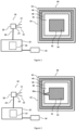
- FIG. 1 a schematic view of the components of a system 10 for illustration purposes of a typical application of evaluating a status of a material is shown in Figure 1 .
- the system is configured to evaluate a status of a molten material and a refractory or insulating material forming part of a furnace 30.
- coaxial cable 20 is selected to have a physical length from computer-based processor 22 to feeding transition section 18, such that a propagation time of an EM wave propagating between first end and second end of coaxial cable 20 is larger than a propagation time of any EM wave of interest to be measured by system 10.
- the propagation time of the EM wave propagating throughout the length of coaxial cable 20 is larger than the propagation time of the EM wave propagating throughout EM wave launcher 12 plus the propagation time of the EM wave propagating through the walls of Furnace 30.
- Those skilled in the art will realize that alternative ways of implementing system 10 include selecting coaxial cable 20 to be electrically very small in length or integrating feeding transition section 18 with computer-based processor 22, in which case coaxial cable 20 would not be required.
- EM wave launcher 12 is typically implemented by means of an antenna with a radiation pattern primarily directed within a hemisphere and having a main radiation lobe, such that the levels of both backlobes and sidelobes is at least -10 dB with respect to the directivity of the antenna, which results in low back-lobe radiation and low scattering of RF signals transmitted and received by EM wave launcher 12.
- EM wave launcher 12 is physically configured to have radiating elements having a smooth topology to prevent abrupt transitions of current flowing on EM wave launcher 12.
- EM wave launcher 12 includes a feeding transition section 18 designed to minimize multiple internal reflections of EM waves.
- an RF absorber material placed in the surroundings of EM wave launcher 12 or a variable conductivity material used as part of EM wave launcher 12 are effective approaches in order to reduce reflections, back-lobe radiation and low scattering of EM waves transmitted or received by EM wave launcher 12.
- EM wave launcher 12 By meeting one or more of these structural and operational requirements of EM wave launcher 12, the multiple reflections of EM waves throughout the system may be significantly reduced, resulting in a low-ringing device with reduced levels of clutter, which is desirable for proper performance of system 10.
- EM wave launcher 12 may be implemented by means of one or more antennas or waveguides or an array of several antennas or waveguides arranged either in a planar or non-planar configuration having one or a variety of polarizations.
- EM wave launcher 12 is placed either contiguously (i.e., in physical contact) or in close proximity to outer surface 43 of furnace 30.
- EM wave launcher 12 is placed contiguously to outer surface 43 during a manual scanning operation of EM wave launcher 12.
- launching end 16 of EM wave launcher 12 is located within 0.635 cm to 5.08 cm (0.25 inches to 2 inches) of outer surface 43 of furnace 30 to expedite the scanning process.
- EM wave launcher 12 is designed to tolerate the required temperature range in the vicinity of outer surface 43 of furnace 30.
- the materials used to build EM wave launcher 12 are selected to allow EM wave launcher 12 to withstand such high temperatures, especially the part of launching end 16 of EM wave launcher 12 that is closer to outer surface 43 of furnace 30.
- Such materials should be able to withstand an ambient temperature of up to approximately 848.56°K (700°F), with outer surface 43 of furnace 30 reaching temperatures of up to approximately 1015.23°K ( 1000°F).
- Computer-based processor 22 comprises an RF subsystem 24, signal and imaging processing subsystems, and an executable computer code or software.
- RF subsystem 24 comprises a tunable signal source, such as a voltage- controlled oscillator or a frequency synthesizer, operable in a frequency band of 0.25 GHz to 30 GHz; at least one directional coupler; a coherent detector; and at least one analog-to-digital converter.
- the signal processing subsystem comprises data storage, including a solid- state drive, hard drive, flash drive, a Secure Digital (SD) memory card or an Electrically Erasable Programmable Read-Only Memory (EEPROM), commercially available as well-known to those skilled in the art, and data processing algorithms.
- the imaging processing subsystem comprises databases, such as MySQL, an open-source relational database management system, and imaging processing algorithms. Those skilled in the art will recognize that data processing and image processing algorithms are implemented by means of one or a combination of more than one technique.
- System 10 also includes an image visualization subsystem 26 comprising tools for image handling and displaying.
- image visualization subsystem 26 comprising tools for image handling and displaying.
- RF subsystem 24 components of computer-based processor 22 have not been shown as these components are not critical to the explanation of this embodiment. Those of ordinary skill in the art will realize that various arrangements of RF subsystem 24 components may be possible and additional components, such as filters, impedance matching networks, amplifiers, non-coherent detectors and other test instrumentation are available to be used in different - ways to implement the functionality of RF subsystem 24 of computer-based processor 22 as known in the art.
- furnace 30 comprises a chamber 32 containing a molten material 34, and a first layer 36, a second layer 38, a third layer 40, and a fourth layer 42 of refractory or insulating material.
- Furnace 30 is representative of applications used in the glass, steel, and plastic industries. In these applications, chamber 32 is typically surrounded by multiple layers of material to prevent heat loss and leakage of molten material to the outside of furnace 30 and as a safety measure to workers and equipment operating in the surroundings of furnace 30.
- first layer 36 of refractory material is contiguous to (i.e., in physical contact with) chamber 32.
- Each of layers 36, 38, 40, and 42 has an outer surface and an inner surface opposite the outer surface, such that the inner surface is closer to chamber 32.
- the inner walls of chamber 32 will degrade during operation of furnace 30. The effects of this degradation include inner surface erosion, stress cracks, and refractory material diffusion into the molten material.
- molten material 34 such as molten glass, at high temperatures erodes and degrades the inner walls of chamber 32 and surrounding layers 36, 38, 40, and 42, creating a high risk for molten material leakage.
- Typical thickness values of refractory and insulation material of furnace walls range from 0.635 cm to 30.48 cm (0.25 inches to 12 inches).
- FIG 2 shows system 10 (in reference to Figure 1 ), which is not according to the invention, wherein a cross-sectional top view of furnace 30 in which molten material 34a has penetrated layers 36 and 38 is shown for illustration purposes only.
- EM wave launcher 12 is set up to evaluate the status of molten material 34a, and more specifically to determine a presence of molten material 34a in any of the materials forming layers 36, 38, 40, and 42. In general, the location where molten material 34a has penetrated into other materials is unknown.
- EM wave launcher 12 may be placed at various locations around surface 43 of furnace 30 or may be used to scan an area of the walls of furnace 30 to evaluate the status of the materials in the corresponding regions to locate the area in which a leakage of molten material 34a has occurred.
- EM wave launcher 12 may be placed at various locations around surface 43 of furnace 30 or may be used to scan an area of the walls of furnace 30 to evaluate the status of the materials in the corresponding regions to locate the area in which a leakage of molten material 34a has occurred.
- Those skilled in the art will realize that different ways of scanning an area of the walls of furnace 30 may be implemented, including mechanical and electronic scanning, performed manually or automatically.
- Figures 3A to 3C show various configurations of a scanning system using a portable device to evaluate the leakage of molten material 34a into the refractory layers 36, 38, 40, and 42 of furnace 30, according to certain aspects of the invention.
- Figure 3A shows a two-dimensional top view of a compact, portable unit 44, comprising an EM wave launcher, a feeding transition section, and an RF subsystem, mounted on a first structural support 46.
- first structural support 46 consists of a rail that runs substantially parallel to the area of the floor immediately adjacent to outer surface 43 of furnace 30. Rail 46 attaches to a second structural support of furnace 30, comprising I- beams 48a and 48b, that forms part of a structure that provides mechanical stability to furnace 30.
- I-beams 48a and 48b are made of steel and are separated from each other by a distance of 0.9144 meters (3 feet) to 3.048 meters (10 feet), depending on the type and size of furnace 30.
- Rail 46 is made of aluminum with hardened and ground steel raceways. Rail 46 runs separated from, but in close proximity and substantially parallel to, outer surface 43 of furnace 30.
- the dimensions of rail 46 are approximately 5.08 cm (2 inches) in width, 5.08 cm (2 inches) in height, and 4.2672 meters (14 feet) in length, such that rail 46 can be mechanically attached to adjacent I-beams 48a and 48b.
- the separation between rail 46 and outer surface 43 must provide enough spacing for unit 44 to fit between rail 46 and outer surface 43 such that the separation between unit 44 and outer surface 43 is substantially invariable and within 5.08 cm (2 inches). Thus, for scanning around outer surface 43, unit 44 is not in physical contact with furnace 30.
- rail 46 may be constrained by other structural parts located adjacent to furnace 30, such as I-beams 48a and 48b.
- Unit 44 is mechanically attached to a side of rail 46 by means of a first extension arm 46a, which extends substantially perpendicular to rail 46 and is substantially parallel to the area of the floor immediately adjacent to outer surface 43 of furnace 30.
- Extension arm 46a consists of a small steel block having two edges that slide into the steel raceways of rail 46 and serves as a carriage to unit 44.
- extension arm 46a may have a plurality of threaded holes that allow other mechanical parts to attach to extension 46a.
- unit 44 may be attached directly underneath or above rail 46.
- Rail 46 provides a guide for unit 44 to run along the length of rail 46 as part of a motion system driven by a first stepper motor 49 (e.g., Oriental Motors PK543AW) having two taper hobbed gears with a 10:1 ratio to push and pull unit 44, using an ANSI #25 roller chain system.
- motor 49 drives a shaft, which couples to a steel driver sprocket of approximately 6.35-cm (2.5-inch) major diameter and a 0.635-cm (0.25-inch) pitch, by means of a steel shaft-to-sprocket coupling.
- motor 49 is positioned at a location close to a first end of rail 46, such that a second end of rail 46, opposite the first end, is separated from the first end by the length of rail 46.
- roller chain engages with the driver sprocket and both ends of the roller chain attach to extension arm 46a by means of a chain attachment consisting of, for example, a screw.
- a chain attachment consisting of, for example, a screw.
- the roller chain engages with a steel idler sprocket, of about 4.318-cm ( 1.7-inch) major diameter and a 0.635-cm (0.25-inch) pitch, which puts tension on the roller chain and allows a smooth movement of the roller chain.
- the length of the roller chain is approximately twice the length of rail 46 to allow the roller chain to go back and forth once from the first end to the second end of rail 46.
- This arrangement provides a motion of unit 44 of about 2.54 cm (one inch) along rail 46 as the motor shaft of motor 49 rotates approximately 1.26 revolutions.
- extension arm 46a is able to slide from substantially the first end to the second end of rail 46 along the raceways of rail 46.
- motor 49 mechanically attaches to I-beams 48a and 48b by means of a custom clamping mechanism consisting of two steel plates on either side of each I-beam 48a and 48b and threaded rods attaching the two plates together.
- This configuration allows unit 44 to evaluate an area of outer surface 43 of furnace 30 along the length of rail 46.
- other means for motor 49 to move unit 44 include a motion system based on a rack- and-pinion, a belt, a rod, or a cable.
- Rail 46 is permanently or temporarily attached to a wall of furnace 30, to I-beams 48a and 48b, or is installed just for the purpose of a single evaluation. Moreover, where one or more units of rail 46 are installed at various locations of I-beams 48a and 48b or a single unit of rail 46 is repositioned at multiple locations for evaluation of different areas of furnace 30, it will result beneficial for unit 44 to be easily removable from, and installed to, rail 46.
- a second extension arm 46b is mechanically attached, and substantially perpendicular, to first extension arm 46a and to the area of the floor immediately adjacent to outer surface 43 of furnace 30.
- second extension arm 46b provides a guide for unit 44 to run along an imaginary axis that is substantially parallel to outer surface 43 of furnace 30 and is substantially perpendicular to the floor immediately adjacent to outer surface 43 of furnace 30 at a substantially uniform separation from furnace 30.
- extension arm 46b provides structural stability to unit 44 that reduces wavering of unit 44 while in motion.
- Unit 44 encloses a second stepper motor (not shown), which allows unit 44 to be pushed and pulled along the length of second extension arm 46b. This arrangement allows unit 44 to evaluate an area of outer surface 43 of furnace 30 along the length of second extension arm 46b.
- First stepper motor 49 and a second stepper motor may be controlled by a computer-based processor by means of control wires as is well-known to those skilled in the art.
- First stepper motor 49 may be placed adjacent to or within unit 44. Moreover, a two-axis stepper motor may be included in unit 44 to provide the functions of first stepper motor 49 and the second stepper motor. Furthermore, a third stepper motor (not shown) or a three-axis stepper motor may be used to enable unit 44 to move along a third axis, substantially perpendicular to surface 43, to adjust the distance between unit 44 and outer surface 43 of furnace 30 to be substantially uniform or to set up a preferred value for calibration or improved performance, typically ranging from zero (unit 44 touching outer surface 43) to 5.08 cm (2 inches), according to the mode of evaluation selected and the EM wave launcher implemented as part of unit 44.
- Figure 3C shows a two-dimensional top view of another configuration, wherein a telescopic scanning system is used to evaluate the leakage of molten material 34a into the refractory layers 36, 38, 40, and 42 of furnace 30.
- This configuration comprises a compact, portable unit 44, including an EM wave launcher, a feeding transition section, and an RF subsystem mounted on a telescopic arm 41.
- Telescopic arm 41 is positioned such that an imaginary axis along the length of telescopic arm 41 is substantially parallel to outer surface 43 of furnace 30 and is substantially parallel to the floor immediately adjacent to outer surface 43 of furnace 30 at a substantially uniform separation from furnace 30.
- a first structural support 45 consisting of a post, stands substantially parallel to outer surface 43 of furnace 30 and substantially perpendicular to telescopic arm 41.
- Telescopic arm 41 mechanically attaches to post 45, such that a two- axis stepper motor (not shown) located in a hollow section of post 45 enables motion of telescopic arm 41 along both post 45 and the imaginary axis along the length of telescopic arm 41 by means of mechanical gears.
- other means of moving telescopic arm 41 include a chain or belt, a pneumatic system, and a hydraulic system, all without departing from the spirit and scope of the invention.
- the arrangement shown in Figure 3C also enables unit 44 to scan a two- dimensional area of outer surface 43 of furnace 30 to evaluate the presence of molten material 34a into the refractory layers 36, 38, 40, and 42 of furnace 30 or a status of these materials in the regions substantially perpendicular to the area scanned by unit 44.
- Telescopic arm 41 extends separated from, but in close proximity and substantially parallel to, outer surface 43 of furnace 30.
- the positioning of telescopic arm 41 and post 45 must be selected such that the separation between unit 44 and outer surface 43 is substantially invariable and within 5.08 cm (2 inches).
- unit 44 is not in physical contact with furnace 30.
- the location of telescopic arm 41 and post 45 is constrained by other structural parts located adjacent to furnace 30, such as I-Beams 48a and 48b.
- telescopic arm 41 comprises three cylindrical tubular sections that are assembled co-axially along an imaginary axis along the length and through the center of each section to form an elongated arm larger than each of these sections.
- One end of each section has a larger diameter of one end of an adjacent section such that a portion of one section securely fits into a portion of an adjacent section with a larger diameter.
- Unit 44 mechanically attaches to the section of telescopic arm 41 having the smallest diameter by means of two clamps (not shown) that fit on telescopic arm 41 and unit 44.
- the dimensions of telescopic arm 41 are approximately 3.048 meters (10 feet) in total length with a 5.08-cm (2-inch) largest diameter and a 2.54-cm (1-inch) lowest diameter.
- Post 45 consists of a 1.8288-meter (6-foot) hollow tube having a square cross-section of 7.62-cm (3-in) side.
- Telescopic arm 41 mechanically attaches to post 45 at the section of telescopic arm 41 having the largest diameter, through the use of clamps, screws, or other similarly configured fasteners that fit on telescopic arm 41 and post 45.
- the length and rigidity of telescopic arm 41 are selected to be large enough to provide a structural stability that reduces wavering of unit 44 while in motion.
- Telescopic arm 41 is permanently attached to post 45 or a structural part of furnace 30 or installed just for the purpose of a single evaluation. Alternatively, one or more units of telescopic arm 41 are installed at various locations of post 45 or a single unit of telescopic arm 41 is repositioned at multiple locations for evaluation of different areas of furnace 30. Furthermore, telescopic arm 41 attaches to unit 44 and to post 45 by other means including screws, bolts, fasteners, and straps, as known in the art.
- telescopic arm 41 and post 45 is rotated 90 degrees, such that telescopic arm 41 is substantially perpendicular, and post 45 is substantially parallel, to the floor immediately adjacent to outer surface 43 of furnace 30.
- This arrangement will also enable unit 44 to scan a two-dimensional area of outer surface 43 of furnace 30.
- each stepper motor is able to push and pull telescopic arm 41, and as a result unit 44, by means of a number of ways, including a chain, belt, rod, or cable as known to those skilled in the art.
- unit 44 moves along a third axis allows a more efficient evaluation of furnace 30 by enabling unit 44 to avoid obstacles that may protrude from or be adjacent to outer surface 43 of furnace 30. Alternatively, unit 44 is manually moved over different parts of furnace 30 to evaluate specific areas of outer surface 43.
- unit 44 communicates with a computer-based processor by means of a universal serial bus (USB) cable.
- USB universal serial bus
- an Ethernet cable or a wireless communication system, including Wi-Fi, USB-over- Wi-Fi, or Bluetooth may be used to link unit 44 and a computer-based processor for controlling the data acquisition and performing the subsequent data processing.
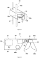
- Figures 4A and 4B show various aspects of a configuration of a compact, portable unit 44, comprising EM wave launcher 50, feeding transition section 52, coaxial connector 54, and a housing 56, mounted on an extension arm 46b and an actuation arm 47.
- Figure 4A shows a perspective view of a compact, portable unit 44 at a specific position along extension arm 46b and actuation arm 47.
- Extension arm 46b consists of a general purpose, circular cross-section steel rod of preferably approximately 1.27 cm (0.5 inches) in diameter and about 91.44 cm (3 feet) long to provide mechanical guidance and structural stability to portable unit 44.
- actuation arm 47 consists of a general purpose, fully threaded circular cross-section steel rod (Acme 1/4-16), having a major diameter of approximately 0.635 cm ( 0.25 inches), 6.3 threads per centimeter ( 16 threads per inch), and a length of about 91.44 cm (3 feet) that attaches to a stepper motor 58 ( Figure 4B ) within unit 44 to move unit 44 along extension arm 46b.
- Extension arm 46b and actuation arm 47 mechanically attach to extension arm 46a that rides on the raceways of rail 46. More specifically, extension arm 46b is threaded at a first end close to extension arm 46a, such that extension arm 46b screws into a first threaded hole in extension arm 46a. Likewise, actuation arm 47 screws into a second threaded hole in extension arm 46a.
- FIG 4B shows a two-dimensional top view of portable unit 44, in which EM wave launcher 50 is implemented by means of an exponentially-shaped dual-ridge, single linearly-polarized horn antenna fed thru a Sub-Miniature version A (SMA) coaxial connector and an SMA-to-N type adapter 54.
- antenna 50 is designed to operate in the frequency band from 1 GHz to 10 GHz.
- Ends 16a and 16b of antenna 50, which are opposite to feeding transition section 52, have an approximate length of 7.366 cm (2.9 inches) and have a maximum separation of about 8.89 cm (3.5 inches).
- Feeding transition section 52 allows the transitioning of RF signals going either from coaxial connector and adapter 54 to antenna 50 or from antenna 50 to coaxial connector and adapter 54.
- EM wave launcher 50 is implemented by means of a dual linearly-polarized antenna or an elliptically-polarized antenna.
- antenna 50 meets the requirements of a low-ringing scanning device due to a smooth physical topology (exponentially-shaped ridges), an integrated feeding transition design, and structural configuration, which results in low back-lobe radiation and low scattering of RF signals transmitted and received by antenna 50.
- Housing 56 is made of aluminum and encloses a stepper motor 58 (e.g., Oriental Motors PK546PA) and RF subsystem 24.
- Stepper motor 58 moves unit 44 in both directions along extension arm 46b by means of mechanical gears attached to stepper motor 58 and actuation arm 47.
- motor 58 drives a first spur gear made of an aluminum alloy, having for example 24 teeth and a pressure angle of 20 degrees.
- the first spur gear drives a second stainless steel spur gear, having 40 teeth and a pressure angle of 20 degrees that is tapped for actuation arm 47 (Acme 1/4-16).
- stepper motor 58 is controlled by a computer-based processor by means of a five-wire control cable connected to a D -Sub 9, size E connector mounted on a side of housing 56 using two screws. This arrangement provides a smooth movement of unit 44 along extension arm 46b as the motor shaft rotates approximately 26.66 revolutions for unit 44 to move 2.54 cm (one inch) along extension arm 46b.
- RF subsystem 24 is implemented by means of a single-port vector network analyzer (e.g., Copper Mountain Planar R140), operating as a reflectometer, to measure the amplitude and phase of the RF signals reflected from furnace 30 after being transmitted by RF subsystem 24.
- Vector network analyzer 24 communicates with a computer-based processor by means of a USB cable through a USB connector mounted on a side of housing 56 using two screws.
- Housing 56 consists of a box having two opposite sides substantially parallel with different dimensions. As a result, housing 56 has two opposite sides that are not parallel. The side longer in length than the corresponding opposite parallel side of housing 56 has -dimensions of approximately 7.62 cm ( 3 inches) in width and 12.7 cm (5 inches) in length. The side shorter in length than the corresponding opposite parallel side of housing 56 has exemplary dimensions of approximately 7.62 cm ( 3 inches) in width and 10.16 cm (4 inches) in length. All sides of housing 56 have a thickness of about 0.15875 cm (1/16 inches).
- housing 56 has an extension plate 56a, with dimensions of approximately 7.62 cm (3 inches) by 7.62 cm (3 inches) by 0.3175 cm (1/8 inches), to allow antenna 50 and feeding transition section 52 to mechanically attach to housing 56 by means of four bolts (not shown) and become an integral part of unit 44.
- Antenna 50 is centrally positioned in extension plate 56a for increased compactness of unit 44.
- Those skilled in the art will realize other ways of attaching antenna 50 and feeding transition section 52 to housing 56, including by means of glue, screws, soldering, clamps, and fasteners.
- portable unit 44 fits within a volume defined by a box of approximately 20.16-cm ( 8-inch) length, 7.62-cm (3-inch) width, and 7.62-cm (3-inch) height, wherein the length of unit 44 is defined by the length of housing 56, including extension plate 56a.
- unit 44 is disposed such that an imaginary axis along the length of unit 44 is substantially parallel to both surface 43 of furnace 30 and to the area of the floor immediately adjacent to outer surface 43 of furnace 30.
- unit 44 is disposed such that ends 16a and 16b of antenna 50 are adjacent and substantially parallel to, and within 0.635 to 5.08 cm (0.25 to 2 inches) of, the surface under evaluation.
- antenna 50 is not in physical contact with the surface under evaluation to facilitate the operational motion of portable unit 44.
- portable unit 44 is also able to operate while ends 16a and 16b of antenna 50 are at distances smaller than 0.635 cm (0.25 inches) from the surface under evaluation.
- housing 56 has multiple openings to allow coaxial connector 54 to directly connect to a coaxial input port of vector network analyzer 24, resulting in no need to use a coaxial cable; to provide a means for extension arm 46b and actuation arm 47 to go through housing 56, such that portable unit 44 can slide along extension arm 46b; to allow control wires of stepper motor 58 and control cables of network analyzer 24 to communicate with a computer-based processor; and to provide access to electrical cables to deliver power to stepper motor 58 and network analyzer 24.
- battery-included devices or one or more batteries are enclosed within housing 56 to supply power to a battery-operated stepper motor 58 or a network analyzer 24, such that access to electrical cables is not required.
- Placement of RF subsystem 24 in a location that requires no need of a coaxial cable contributes to a more stable data acquisition and eliminates the adverse effects caused by movement of such cable.
- Figure 5 shows a perspective view of another configuration of a low-ringing EM wave launcher 55 for use with unit 44, comprising a quad-ridge, dual-polarization horn antenna having smooth edges and designed to operate in the 3 to 8 GHz frequency band.
- Smooth ridges 59a, 59b, 59c, and 59d contribute to improve the antenna frequency response and reduce the clutter caused by reflections and "ringing" effects of EM waves propagating along ridges 59a, 59b, 59c, and 59d of EM wave launcher 55.
- each ridge 59a, 59b, 59c, and 59d has been shaped following an elliptical curve.
- the smooth shaping of ridges 59a, 59b, 59c, and 59d reduce the system clutter level by up to more than 10 dB, as compared to antenna 50 of Figure 4 , at certain frequency bands of interest.
- EM wave launcher 55 is fed at coaxial cable connectors 53a and 53b, which transition from a coaxial cable transmission line (not shown) to the quad-ridge waveguide section by means of a cavity-backed transition section 57.
- EM wave launcher 55 meets the low-ringing requirements due to a smooth physical topology (elliptical ridges), a cavity-backed coaxial- to-ridge feeding design, and a structural configuration resulting in low back-lobe radiation and low scattering.
- Figure 6 shows a perspective view of another configuration of a compact, portable unit 60, comprising an EM wave launcher 62, consisting of a planar antenna, and a housing 64 mounted at a specific position along extension arm 46c and actuation arm 47a.
- Extension arm 46c consists of a circular cross-section rod, made of metal, of for example approximately 0.635 cm ( 1/4 inches) in diameter and 91.44 cm (3 feet) long that provides mechanical guidance and structural stability to portable unit 60.
- Actuation arm 47a consists of a metal screw of for example approximately 0.635 cm ( 1/4 inches) in diameter and 91.44-cm (3-foot) long that attaches to a stepper motor (not shown) within unit 60 to move unit 60 along extension arm 46c.
- Housing 64 is made of aluminum and consists of a box of approximately 12.065-cm ( 4.75-inch) length (longest dimension), 5.08-cm ( 2-inch) width (measured normal to the surface under evaluation), and 7.62-cm ( 3-inch) height, wherein the length and height of portable unit 60 are defined by the length and height of housing 64, respectively.
- the overall width of unit 60 is defined by the width of housing 64 and the width of planar antenna 62. All sides of housing 64 have a thickness of for example about 0.15875 cm (1/16 inches).
- housing 64 comprises multiple openings, and encloses a stepper motor, an RF subsystem (not shown), and mechanical, electrical, and control parts similar to those described in the configuration shown in Figure 4B .
- This arrangement allows a computer- based processor to control data collection and motion of portable unit 60.
- Portable unit 60 also comprises a feeding transition section and a coaxial connector to electrically connect planar antenna 62 to the RF subsystem.
- planar antenna 62 may be mechanically attached to, and centrally positioned on, a side of housing 64 by means of four bolts (not shown).
- planar Antenna 62 is designed to operate in the frequency band from 1 GHz to 10 GHz as an elliptically- or a single- or dual linearly-polarized antenna.
- Those skilled in the art will realize other ways of attaching planar antenna 62 to housing 64, including by means of glue, screws, soldering, clamps, and fasteners.
- unit 60 is disposed such that an imaginary axis along the length of unit 60 is substantially parallel to the surface under evaluation and to the area of the floor immediately adjacent to the surface under evaluation. Also, unit 60 is disposed such that planar antenna 62 is adjacent and substantially parallel to, and preferably within 0.635 to 5.08 cm (0.25 to 2 inches) of, the surface under evaluation. In other words, planar antenna 62 not in physical contact with the surface under evaluation.
- Figures 7A and 7B show various aspects of a low-ringing EM wave launcher 62 for use with portable units 44 and 60 comprising a broadband, dual- polarization cross-dipole, planar antenna designed to operate in the 3 to 10 GHz frequency band, in accordance with certain aspects of a particular configuration of the invention. More specifically, Figure 7A shows a perspective view of planar antenna 62, which includes four dipole arms 70a, 70b, 70c, and 70d, substantially identical to each other, and disposed on a layer of a first dielectric substrate 72, having approximate dimensions of for example 5.842 cm (2.3 inches) in length and height and 0.127 cm (0.05 inches) in width.
- Substrate 77 has the same dimensions of substrate 72 and is adjacent to feeding transition section 71.
- Each dipole arm 70a, 70b, 70c, and 70d of planar antenna 62 consists of a thin layer of conductive material having an oval shape with a maximum width of approximately 1.27 cm (0.5 inches) to provide a broadband frequency response.
- Dipole arms 70a, 70b, 70c, and 70d of planar antenna 62 are arranged on substrate 72, having one end of each dipole arm 70a, 70b, 70c, and 70d slightly modified to converge around a center 79.
- dipole arms 70a, 70b, 70c, and 70d of planar antenna 62 are arranged in a way that resembles a 4-petal flower, such that the distance from center 79 to the farthest point of each dipole arm 70a, 70b, 70c, and 70d is approximately 1.778 cm (0.7 inches).
- Figure 7B shows a two-dimensional cross-sectional side view of planar antenna 62, in which feeding transition section 71 enables a transitioning from a coaxial transmission line 73 to a twin-line transmission line 78b by means of a feed point 78a backed by a cavity 75.
- dipole arms 70a, 70b, 70c, and 70d are directly fed at center 79 by a dual linearly-polarized twin-line transmission line 78b.
- Feeding transition section 71 is made of a hollow block of conductive material of approximately 3.556 cm ( 1.4 inches) in length and height and 1.27 cm (0.5 inches) in width. Thus, the overall width of planar antenna 62, including feeding transition section 71 is about 3.43 cm ( 1.35 inches).
- Cavity 75 within feeding transition section 71, has a box shape with approximate dimensions of 2.286 cm (0.9 inches) in length and height and 0.508 cm (0.2 inches) in width. Each side of cavity 75 is substantially parallel to a corresponding side of the block forming feeding transition section 71.
- One side of cavity 75 has a center opening that is positioned at the location of feed point 78a to improve the performance of feeding transition section 71.
- feeding transition section 71 has an opening on one side just large enough to allow coaxial transmission line 73 to access feed point 78a.
- Planar antenna 62 also comprises a piece of RF absorber material 76 disposed on substrate 77, and within substrate 74, in a way that RF absorber material 76 is substantially underneath each of dipole arms 70a, 70b, 70c, and 70d, such that the four pieces of RF absorber material 76 form a square annular-ring.
- the presence of absorber material 76 significantly attenuates the RF signals transmitted by dipole arms 70a, 70b, 70c, and 70d into substrate 74, resulting in a substantial reduction of the overall system clutter.
- substrate 77 provides structural support to absorber material 76.
- air replaces second dielectric substrate 74 and a conductive material, such as a metal plate, replaces RF absorber material 76.
- planar antenna 62 meets the requirements of a low-ringing scanning device due to a smooth physical topology (oval shape) of dipole arms 70a, 70b, 70c, and 70d, a cavity- backed twin-line transmission line feeding design, and a structural configuration, including absorber material 76, which results in low back-lobe radiation and low scattering of RF signals transmitted and received by planar antenna 62.
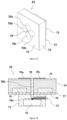
- FIGS 8A and 8B show various aspects of another configuration of a low-ringing EM wave launcher 80 for use with portable units 44 and 60, comprising a dual- ridge, linearly-polarized horn antenna having smooth edges and designed to operate in the 3 to 18 GHz frequency band.
- EM wave launcher 80 comprises a first side 82a and a second side 82b, identical in dimensions and made of a highly conductive material, having an isosceles triangular shape with a 0.38-cm (0.15-inch) truncation at each vertex.
- Sides 82a and 82b are each approximately 0.254 cm (0.1-inch) thick, separated by about 2.032 cm (0.8 inches), and substantially parallel to one another.
- Exponentially-shaped ridges 88a and 88b extend toward one another from and substantially perpendicular to sides 82a and 82b, respectively. At a cavity-backed transition section 87, ridges 88a and 88b are at their closest point, separated by approximately 0.0508 cm (0.02 inches). The separation between ridges 88a and 88b increases as each gets farther from transition section 87 until merging with sides 82a and 82b, respectively.
- Figure 8A illustrates a side view of EM wave launcher 80
- Figure 8B shows a perspective view of EM wave launcher 80.
- EM wave launcher 80 also comprises a layer of a magnetic absorber material 84a, 84b, 86a, 86b, such as the Emerson & Cuming ECCOSORB MCS, having a similar footprint to sides 82a and 82b and at least approximately 0.254 cm (0.1 inches) in thickness.
- Layers 84a and 86a are disposed contiguously and substantially parallel to side 82a.
- layers 84b and 86b are disposed contiguously and substantially parallel to side 82b.
- side 82a is sandwiched in between layers of absorber material 84a and 86a
- side 82b is sandwiched in between layers of absorber material 84b and 86b.
- Layers 84a, 84b, 86a, and 86b are flexible, magnetically loaded, high-loss rubber absorbers and are attached to sides 82a and 82b by means of a pressure sensitive adhesive or silicone-based adhesive that is commercially available.
- Material 84a, 84b, 86a, and 86b and smooth ridges 88a and 88b contribute to improving the antenna frequency response and may reduce the clutter caused by reflections and "ringing" effects of EM waves propagating along ridges 88a and 88b of EM wave launcher 80, by up to more than 15 dB, as compared to antenna 50 of Figure 4 , at the frequency bands of interest.
- EM wave launcher 80 is fed at coaxial connector 83, which transitions from a coaxial cable transmission line (not shown) to the dual-ridge waveguide section by means of cavity-backed transition section 87, as well- known in the prior art.
- Cavity-backed transition section 87 has dimensions of approximately 2.54-cm ( 1-inch) long, 2.54-cm (1-inch) wide, and 0.5-inch height.
- the total length of EM wave launcher 80 is approximately 5.08 cm (2 inches).
- EM wave launcher 80 meets the low- ringing requirements due to a smooth physical topology (exponential ridges), a cavity-backed coaxial-to-ridge feeding design, and a structural configuration resulting in low back-lobe radiation and low scattering.
- EM wave absorber materials are used to reduce the clutter caused by reflections and "ringing" effects, including by means of a material having a variable conductivity, an EM metamaterial, a radiofrequency absorber material, or any combination thereof configured in different geometrical arrangements.
- one or a combination of more than one of these materials may be used as part of EM wave launcher 80, including replacing a piece of EM wave launcher 80, to reduce the clutter caused by reflections and "ringing" effects.
- more than one EM wave launcher 80 arranged in a linear or in a two-dimensional array allows to electronically scan larger areas of a material under evaluation with less or no need to mechanically move EM wave launcher 80; perform faster evaluations; or operate a plurality of EM wave launchers in a multistatic mode, wherein more than one EM wave launcher 80 launches an EM wave, more than one EM wave launcher 80 receives an EM wave, or a combination thereof.
- the plurality of EM wave launchers 80 are arranged in various operational configurations, including a fixed configuration to evaluate or monitor over time a region of a material and a movable configuration as part of either a portable device mounted on a moving apparatus or a handheld device, for both manual and automated operation.
- multiple radiofrequency switches, duplexers, or equivalent devices may be required. More specifically, such multiple components may be required to select the particular EM wave launcher that will transmit or receive an EM wave, and more importantly to synchronize when each EM wave launcher will transmit or receive the corresponding EM wave for a proper multistatic operation as well-known in the prior art.
- Figure 9 shows a snapshot image, for illustration purposes, of actual results of an evaluation of the status of a material in accordance with an embodiment of the invention.
- the snapshot image represents a cross-sectional view, substantially parallel to the outer surface of the furnace corresponding to the region under evaluation, at a specific position in between such outer surface and the furnace chamber. In other words, the snapshot image is taken within one of the refractory layers surrounding the furnace chamber.
- Figure 9 shows a first material 90, consisting of molten material, present within a first region 92a of a second material, consisting of a refractory material.
- a second region 92b of refractory material is separated from first region 92a by joint 94.
- This is representative of a typical furnace built with refractory bricks, wherein first and second regions 92a and 92b are each part of different and adjacent bricks of refractory material.
- molten material 90 has leaked outside of the furnace chamber and is present in first region 92a. Therefore, molten material 90 should have also penetrated into all layers of refractory material in between first region 92a of refractory material and the furnace chamber.
- Figure 9 shows possible results of an evaluation of the status of a material, consisting of a void 96 and a crack 98 in second region 92b of the refractory material.
- Void 96 and crack 98 represent anomalies in the refractory material and may be indicative of wear, tear, or defects in the furnace that may need to be monitored or addressed to prevent additional problems.
- Figure 9 shows a 2D map of anomalies corresponding to a condition and a status of a material in a Cartesian coordinate system.
- the X-axis represents the horizontal position along an axis substantially parallel to both the outer surface of the furnace and the area of the floor immediately adjacent to the outer surface of the furnace.
- Figure 9 provides the status and specific location of furnace anomalies on a plane for the region under evaluation in between the outer surface of the furnace and the furnace chamber. Moreover, a 3D mapping of such region is visualized by combining a plurality of substantially parallel 2D images. A 3D image not only provides the specific location, but also the extent of an anomaly. In addition, the erosion profile and thickness of a particular layer of a material are determined. This is of key importance to estimate the remaining life of a furnace or when a repair of a furnace is needed to prevent major problems.
- a method depicted in Figure 10 for determining a status of the subject material under evaluation, including the presence of a first material within a second material, using EM waves, is performed according to the following:
- measurements of the amplitude and the phase of EM waves may be accomplished in multiple ways, such as through use of a network analyzer to measure the S11 scattering parameter over a frequency band, using a monostatic configuration (a single device to both launch EM waves and receive EM waves) or to measure the S 1 scattering parameter, over a frequency band, using a bistatic configuration (a first device to launch EM waves and a second device 2 to receive EM waves) or a multistatic configuration (more than one device to launch EM waves, more than one device to receive EM waves, or a combination thereof).
- time-domain measurements are performed by transmitting a pulse with a duration of about one nanosecond and measuring the magnitude of the reflected pulse in the time domain.
- the steps above indicated can be correspondingly adjusted for specific architectures of the chamber containing the first material and multilayer structures comprising different materials external to the chamber, as well as other constraints, including the number of structural layers, type and dimensions of materials, operating frequency band, type of EM wave launcher, and accessibility and available area for location of the EM wave launcher.
- the described method is usable to create images of different views, including two-dimensional frontal and side views and three-dimensional perspective views, of one or more layers corresponding to the region under evaluation.
- the method is usable to determine the parts of any layer of material that have been penetrated by the first material, including the location and extent of the penetration, as well as to determine the thickness, homogeneity, discontinuities, and surface characteristics of a material.
- typically additional data processing is required. However, there is no need to perform additional measurements or data collection procedures no matter what is the actual number of layers in between the second material and the chamber or between the EM wave launcher and the chamber.
- intermediate peak values over the clutter plus noise level may appear between the reference point associated with an EM wave reflected from the outer, near surface of the material under evaluation and the peak value associated with an EM wave reflected from the inner, remote surface of the material under evaluation; it being understood that the intermediate peak values may be associated with flaws of the material under evaluation existing between the outer, near surface of the material under evaluation and the inner, remote surface of the material under evaluation.
- the calibration of the time domain data to distance domain data includes the subtraction of the delay time (distance) associated with the EM wave launcher and cables.
- the frequency dispersion effects of the EM wave launcher and the material under evaluation are removed, if necessary, by normalizing the measured data of the material under evaluation with respect to another set of measured data corresponding to a reference configuration, by way of non-limiting example, of a known characteristic and thickness of a material similar to the material under evaluation, through processes well known to those skilled in the art.
Landscapes
- Physics & Mathematics (AREA)
- General Physics & Mathematics (AREA)
- Electromagnetism (AREA)
- Health & Medical Sciences (AREA)
- Life Sciences & Earth Sciences (AREA)
- Chemical & Material Sciences (AREA)
- Analytical Chemistry (AREA)
- Biochemistry (AREA)
- General Health & Medical Sciences (AREA)
- Immunology (AREA)
- Pathology (AREA)
- Length-Measuring Devices Using Wave Or Particle Radiation (AREA)
Claims (17)
- Dispositif (44, 60) pour évaluer un état d'un premier matériau enfermé par un second matériau, comprenant :a. un boîtier (56, 64) fixé mécaniquement à une première structure de support ;b. un lanceur d'ondes électromagnétiques (50, 55, 62, 80) ayant une extrémité d'alimentation et une extrémité de lancement, dans lequel ladite extrémité d'alimentation comporte un mécanisme d'alimentation configuré pour exciter une onde électromagnétique capable de se propager à travers ledit lanceur d'ondes électromagnétiques (50, 55, 62, 80), dans lequel ladite extrémité de lancement est configurée pour transmettre ladite onde électromagnétique à une région externe audit lanceur d'ondes électromagnétiques (50, 55, 62, 80) et est physiquement structurée pour réduire une pluralité de réflexions et pour réduire une sonnerie de ladite onde électromagnétique se propageant à travers ladite extrémité de lancement dans une mesure suffisante de manière à permettre la détection d'une onde électromagnétique d'intérêt réfléchie par une présence dudit premier matériau à l'intérieur dudit second matériau, dans lequel ladite extrémité de lancement dudit lanceur d'ondes électromagnétiques (50, 55, 62, 80) a au moins un bord lisse, et dans lequel ledit lanceur d'ondes électromagnétiques (50, 55, 62, 80) est conçu pour retarder la réception de ladite onde électromagnétique d'intérêt réfléchie par ladite présence dudit premier matériau à l'intérieur dudit second matériau pendant une période de temps suffisante pour faire la distinction entre ladite onde électromagnétique réfléchie d'intérêt et une onde électromagnétique parasite réfléchie par une discontinuité dudit second matériau ; etc. une section de transition d'alimentation, dans lequel ladite extrémité d'alimentation adapte un signal radiofréquence depuis et vers ladite onde électromagnétique, et dans lequel ladite extrémité d'alimentation est configurée pour réduire une pluralité de réflexions de ladite onde électromagnétique excitée au niveau de ladite extrémité d'alimentation dans une mesure suffisante de manière à réduire un niveau d'encombrement autrement présent dans ledit lanceur d'ondes électromagnétiques (50, 55, 62, 80), dans lequel ladite section de transition d'alimentation est configurée pour être un élément choisi dans un groupe composé d'une section intégrée à un processeur informatique et d'une section connectée électriquement à une ligne de transmission radiofréquence, dans lequel une longueur physique de ladite ligne de transmission radiofréquence est choisie de sorte qu'un temps de propagation de ladite onde électromagnétique se propageant sur toute ladite longueur de ladite ligne de transmission radiofréquence est supérieur à un temps de propagation de ladite onde électromagnétique se propageant sur tout ledit lanceur d'ondes électromagnétiques (50, 55, 62, 80) plus un temps de propagation de ladite onde électromagnétique se propageant à travers ledit second matériau, afin d'obtenir ladite réception retardée de ladite onde électromagnétique d'intérêt ;dans lequel ledit boîtier (56, 64) monte ledit lanceur d'ondes électromagnétiques (50, 55, 62, 80) et ladite section de transition d'alimentation.
- Dispositif (44, 60) selon la revendication 1, dans lequel ladite première structure de support comprend une configuration pour permettre une application portable dudit dispositif pour balayer une zone afin d'évaluer ledit état dudit premier matériau.
- Dispositif (44, 60) selon la revendication 1, dans lequel ladite première structure de support comprend un premier bras qui guide un mouvement dudit dispositif dans une première dimension le long d'une longueur dudit premier bras et se fixe à une deuxième structure de support.
- Dispositif (44, 60) selon la revendication 3, comprenant également une troisième structure de support ayant un second bras qui guide un mouvement dudit dispositif dans une seconde dimension le long d'une longueur dudit second bras, dans lequel ladite troisième structure de support se fixe à ladite première structure de support, et dans lequel ledit premier bras de ladite première structure de support est sensiblement perpendiculaire audit second bras de ladite troisième structure de support.
- Dispositif (44, 60) selon la revendication 1, dans lequel ladite première structure de support comprend un bras télescopique (41).
- Dispositif (44, 60) selon la revendication 1, comprenant également un sous-système radiofréquence pour détecter et mesurer lesdites ondes électromagnétiques d'intérêt, dans lequel ledit sous-système radiofréquence est installé dans ledit boîtier (56, 64) et est capable de générer et de détecter une onde électromagnétique dans une plage de fréquences comprise entre 0,25 et 30 GHz.
- Dispositif (44, 60) selon la revendication 1, comprenant également un sous-système radiofréquence pour détecter et mesurer lesdites ondes électromagnétiques d'intérêt, dans lequel ledit sous-système radiofréquence est installé dans ledit boîtier (56, 64) et est capable de générer et de détecter une pluralité d'ondes électromagnétiques associées à une impulsion dans le domaine temporel avec une durée dans la plage comprise entre 0,1 et 10 nanosecondes.
- Dispositif (44, 60) selon la revendication 1, dans lequel ledit lanceur d'ondes électromagnétiques (50, 55, 62, 80) comprend un matériau absorbant les radiofréquences capable d'absorber sensiblement l'énergie électromagnétique, dans lequel ledit matériau absorbant les radiofréquences est positionné pour réduire ladite pluralité de réflexions et pour réduire ladite sonnerie de ladite onde électromagnétique se propageant à travers ledit lanceur d'ondes électromagnétiques (50, 55, 62, 80).
- Dispositif (44, 60) selon la revendication 8, dans lequel ledit matériau absorbant les radiofréquences comprend au moins une couche de matériau absorbant disposée adjacente à ladite extrémité de lancement dudit lanceur d'ondes électromagnétiques (50, 55, 62, 80).
- Dispositif (44, 60) selon la revendication 1, comprenant également une pluralité de lanceurs d'ondes électromagnétiques (50, 55, 62, 80), dans lequel au moins l'un de ladite pluralité de lanceurs d'ondes électromagnétiques (50, 55, 62, 80) transmet ladite onde électromagnétique.
- Dispositif (44, 60) selon la revendication 1, dans lequel ledit dispositif est configuré pour générer un résultat d'une évaluation d'un élément choisi dans un groupe composé dudit état dudit premier matériau et d'un état dudit second matériau.
- Dispositif (44, 60) selon la revendication 1, dans lequel ladite section de transition d'alimentation comprend une broche d'alimentation à cavité.
- Dispositif (44, 60) selon la revendication 1, dans lequel ledit lanceur d'ondes électromagnétiques (50, 55, 62, 80) comprend également un matériau ayant une conductivité variable.
- Procédé pour évaluer un état d'un premier matériau enfermé par un second matériau, comprenant :a. la fourniture d'un boîtier (56, 64) fixé mécaniquement à une première structure de support ; un lanceur d'ondes électromagnétiques (50, 55, 62, 80) ayant une extrémité d'alimentation et une extrémité de lancement, dans lequel ladite extrémité d'alimentation comporte un mécanisme d'alimentation configuré pour exciter une onde électromagnétique capable de se propager à travers ledit lanceur d'ondes électromagnétiques (50, 55, 62, 80), dans lequel ladite extrémité de lancement est configurée pour transmettre ladite onde électromagnétique à une région externe audit lanceur d'ondes électromagnétiques (50, 55, 62, 80) et est physiquement structurée pour réduire une pluralité de réflexions et pour réduire une sonnerie de ladite onde électromagnétique se propageant à travers ladite extrémité de lancement dans une mesure suffisante de manière à permettre la détection d'une onde électromagnétique d'intérêt réfléchie par une présence dudit premier matériau dans ledit second matériau, dans lequel ladite extrémité de lancement dudit lanceur d'ondes électromagnétiques (50, 55, 62, 80) a au moins un bord lisse, et dans lequel ledit lanceur d'ondes électromagnétiques (50, 55, 62, 80) est conçu pour retarder la réception de ladite onde électromagnétique d'intérêt réfléchie par ladite présence dudit premier matériau à l'intérieur dudit second matériau pendant une période de temps suffisante pour faire la distinction entre ladite onde électromagnétique réfléchie d'intérêt et une onde électromagnétique parasite réfléchie par une discontinuité dudit second matériau ; et une section de transition d'alimentation, dans lequel ladite extrémité d'alimentation adapte un signal radiofréquence depuis et vers ladite onde électromagnétique, et dans lequel ladite extrémité d'alimentation est configurée pour réduire une pluralité de réflexions de ladite onde électromagnétique excitée au niveau de ladite extrémité d'alimentation, dans une mesure suffisante de manière à réduire un niveau d'encombrement autrement présent dans ledit lanceur d'ondes électromagnétiques (50, 55, 62, 80), dans lequel ladite section de transition d'alimentation est configurée pour être un élément choisi dans un groupe composé d'une section intégrée à un processeur informatique et d'une section connectée électriquement à une ligne de transmission radiofréquence, dans lequel une longueur physique de ladite ligne de transmission radiofréquence est choisie de sorte qu'un temps de propagation de ladite onde électromagnétique se propageant sur toute ladite longueur de ladite ligne de transmission radiofréquence est supérieur à un temps de propagation de ladite onde électromagnétique se propageant sur tout ledit lanceur d'ondes électromagnétiques (50, 55, 62, 80) plus un temps de propagation de ladite onde électromagnétique se propageant à travers ledit second matériau, afin d'obtenir ladite réception retardée de ladite onde électromagnétique d'intérêt ; dans lequel ledit boîtier (56, 64) loge et monte ledit lanceur d'ondes électromagnétiques (50, 55, 62, 80) et ladite section de transition d'alimentation ;b. la détermination d'un type d'un lanceur d'ondes électromagnétiques à faible sonnerie (50, 55, 62, 80) à utiliser pour évaluer ledit état d'une région dudit premier matériau ;c. le placement de ladite extrémité de lancement dudit lanceur d'ondes électromagnétiques (50, 55, 62, 80) adjacente à ladite région dudit premier matériau ;d. le lancement d'une pluralité d'ondes électromagnétiques, se propageant dans une plage de fréquences prédéterminée, dans ladite région dudit premier matériau ;e. la mesure d'un ensemble de données relatives à un groupe d'ondes électromagnétiques entrant dans ledit lanceur d'ondes électromagnétiques (50, 55, 62, 80) en conséquence d'une propagation de ladite pluralité d'ondes électromagnétiques lancées par ledit lanceur d'ondes électromagnétiques (50, 55, 62, 80) ; etf. la détermination dudit statut dudit premier matériau sur la base d'une identification de ladite présence dudit premier matériau dans ledit second matériau.
- Procédé selon la revendication 14, dans lequel ledit état comporte un emplacement et une étendue d'une pénétration dudit premier matériau à l'intérieur dudit second matériau.
- Procédé selon la revendication 14, dans lequel la détermination dudit état dudit premier matériau comprend également :a. la fourniture d'un moyen pour stocker ledit ensemble de données ;b. la fourniture d'un processeur de données informatique pour traiter ledit ensemble de données afin d'évaluer ledit état dudit premier matériau ;c. le transfert dudit ensemble de données dudit moyen pour stocker ledit ensemble de données audit processeur de données informatique ; etd. le traitement dudit ensemble de données au moyen d'au moins un procédé de traitement de données.
- Procédé selon la revendication 14, dans lequel ledit traitement dudit ensemble de données détermine une épaisseur dudit second matériau.
Applications Claiming Priority (3)
| Application Number | Priority Date | Filing Date | Title |
|---|---|---|---|
| US201462010654P | 2014-06-11 | 2014-06-11 | |
| US201462073193P | 2014-10-31 | 2014-10-31 | |
| PCT/US2015/034620 WO2015191415A1 (fr) | 2014-06-11 | 2015-06-08 | Dispositif et procédé d'évaluation de matériau |
Publications (4)
| Publication Number | Publication Date |
|---|---|
| EP3155363A1 EP3155363A1 (fr) | 2017-04-19 |
| EP3155363A4 EP3155363A4 (fr) | 2017-12-13 |
| EP3155363C0 EP3155363C0 (fr) | 2025-03-26 |
| EP3155363B1 true EP3155363B1 (fr) | 2025-03-26 |
Family
ID=58358995
Family Applications (1)
| Application Number | Title | Priority Date | Filing Date |
|---|---|---|---|
| EP15806456.8A Active EP3155363B1 (fr) | 2014-06-11 | 2015-06-08 | Dispositif et procédé d'évaluation de matériau |
Country Status (1)
| Country | Link |
|---|---|
| EP (1) | EP3155363B1 (fr) |
Family Cites Families (2)
| Publication number | Priority date | Publication date | Assignee | Title |
|---|---|---|---|---|
| US8026859B2 (en) * | 2008-08-07 | 2011-09-27 | Tdk Corporation | Horn antenna with integrated impedance matching network for improved operating frequency range |
| WO2013086126A1 (fr) * | 2011-12-06 | 2013-06-13 | Paneratech, Inc. | Sonde à micro-ondes pour matériau réfractaire de four |
-
2015
- 2015-06-08 EP EP15806456.8A patent/EP3155363B1/fr active Active
Also Published As
| Publication number | Publication date |
|---|---|
| EP3155363C0 (fr) | 2025-03-26 |
| EP3155363A4 (fr) | 2017-12-13 |
| EP3155363A1 (fr) | 2017-04-19 |
Similar Documents
| Publication | Publication Date | Title |
|---|---|---|
| US10151709B2 (en) | Device and method for evaluation of a material | |
| US9488601B2 (en) | Material erosion monitoring system and method | |
| TWI390217B (zh) | 天線特性測定裝置及天線特性測定方法 | |
| EP2788135B1 (fr) | Sonde à micro-ondes pour matériau réfractaire de four | |
| US9880110B2 (en) | Material erosion monitoring system and method | |
| US10054367B2 (en) | Asset life optimization and monitoring system | |
| JP2020523571A (ja) | 保温材を取り外さないcui検査用のマイクロ波ホーンアンテナベースのトランスデューサシステム | |
| EP3044830B1 (fr) | Sonde de guide d'onde pour caractérisation non destructive de matériau | |
| US12061155B2 (en) | Method and apparatus for evaluation of a status of a material in metallurgical vessels | |
| CN107192990A (zh) | 外推法测雷达散射截面积 | |
| EP3155363B1 (fr) | Dispositif et procédé d'évaluation de matériau | |
| JP7026125B2 (ja) | 物質浸食監視システム及び方法 | |
| CA2950181C (fr) | Dispositif et procédé d’évaluation de matériau | |
| Charley et al. | Electromagnetic Radiation (EMR) coupling to complex systems: aperture coupling into canonical cavities in reverberant and anechoic environments and model validation. |
Legal Events
| Date | Code | Title | Description |
|---|---|---|---|
| STAA | Information on the status of an ep patent application or granted ep patent |
Free format text: STATUS: THE INTERNATIONAL PUBLICATION HAS BEEN MADE |
|
| PUAI | Public reference made under article 153(3) epc to a published international application that has entered the european phase |
Free format text: ORIGINAL CODE: 0009012 |
|
| STAA | Information on the status of an ep patent application or granted ep patent |
Free format text: STATUS: REQUEST FOR EXAMINATION WAS MADE |
|
| 17P | Request for examination filed |
Effective date: 20161130 |
|
| AK | Designated contracting states |
Kind code of ref document: A1 Designated state(s): AL AT BE BG CH CY CZ DE DK EE ES FI FR GB GR HR HU IE IS IT LI LT LU LV MC MK MT NL NO PL PT RO RS SE SI SK SM TR |
|
| AX | Request for extension of the european patent |
Extension state: BA ME |
|
| DAV | Request for validation of the european patent (deleted) | ||
| DAX | Request for extension of the european patent (deleted) | ||
| A4 | Supplementary search report drawn up and despatched |
Effective date: 20171114 |
|
| RIC1 | Information provided on ipc code assigned before grant |
Ipc: G01M 3/16 20060101ALI20171108BHEP Ipc: G01M 3/40 20060101ALI20171108BHEP Ipc: G01N 22/02 20060101AFI20171108BHEP |
|
| STAA | Information on the status of an ep patent application or granted ep patent |
Free format text: STATUS: EXAMINATION IS IN PROGRESS |
|
| 17Q | First examination report despatched |
Effective date: 20210607 |
|
| GRAP | Despatch of communication of intention to grant a patent |
Free format text: ORIGINAL CODE: EPIDOSNIGR1 |
|
| STAA | Information on the status of an ep patent application or granted ep patent |
Free format text: STATUS: GRANT OF PATENT IS INTENDED |
|
| INTG | Intention to grant announced |
Effective date: 20241223 |
|
| GRAS | Grant fee paid |
Free format text: ORIGINAL CODE: EPIDOSNIGR3 |
|
| GRAA | (expected) grant |
Free format text: ORIGINAL CODE: 0009210 |
|
| STAA | Information on the status of an ep patent application or granted ep patent |
Free format text: STATUS: THE PATENT HAS BEEN GRANTED |
|
| AK | Designated contracting states |
Kind code of ref document: B1 Designated state(s): AL AT BE BG CH CY CZ DE DK EE ES FI FR GB GR HR HU IE IS IT LI LT LU LV MC MK MT NL NO PL PT RO RS SE SI SK SM TR |
|
| REG | Reference to a national code |
Ref country code: GB Ref legal event code: FG4D |
|
| REG | Reference to a national code |
Ref country code: CH Ref legal event code: EP |
|
| REG | Reference to a national code |
Ref country code: DE Ref legal event code: R096 Ref document number: 602015091294 Country of ref document: DE |
|
| REG | Reference to a national code |
Ref country code: IE Ref legal event code: FG4D |
|
| U01 | Request for unitary effect filed |
Effective date: 20250424 |
|
| U07 | Unitary effect registered |
Designated state(s): AT BE BG DE DK EE FI FR IT LT LU LV MT NL PT RO SE SI Effective date: 20250430 |
|
| PG25 | Lapsed in a contracting state [announced via postgrant information from national office to epo] |
Ref country code: RS Free format text: LAPSE BECAUSE OF FAILURE TO SUBMIT A TRANSLATION OF THE DESCRIPTION OR TO PAY THE FEE WITHIN THE PRESCRIBED TIME-LIMIT Effective date: 20250626 |
|
| PGFP | Annual fee paid to national office [announced via postgrant information from national office to epo] |
Ref country code: GB Payment date: 20250627 Year of fee payment: 11 |
|
| PG25 | Lapsed in a contracting state [announced via postgrant information from national office to epo] |
Ref country code: NO Free format text: LAPSE BECAUSE OF FAILURE TO SUBMIT A TRANSLATION OF THE DESCRIPTION OR TO PAY THE FEE WITHIN THE PRESCRIBED TIME-LIMIT Effective date: 20250626 |
|
| PG25 | Lapsed in a contracting state [announced via postgrant information from national office to epo] |
Ref country code: HR Free format text: LAPSE BECAUSE OF FAILURE TO SUBMIT A TRANSLATION OF THE DESCRIPTION OR TO PAY THE FEE WITHIN THE PRESCRIBED TIME-LIMIT Effective date: 20250326 |
|
| PG25 | Lapsed in a contracting state [announced via postgrant information from national office to epo] |
Ref country code: GR Free format text: LAPSE BECAUSE OF FAILURE TO SUBMIT A TRANSLATION OF THE DESCRIPTION OR TO PAY THE FEE WITHIN THE PRESCRIBED TIME-LIMIT Effective date: 20250627 |
|
| U20 | Renewal fee for the european patent with unitary effect paid |
Year of fee payment: 11 Effective date: 20250628 |
|
| PG25 | Lapsed in a contracting state [announced via postgrant information from national office to epo] |
Ref country code: SM Free format text: LAPSE BECAUSE OF FAILURE TO SUBMIT A TRANSLATION OF THE DESCRIPTION OR TO PAY THE FEE WITHIN THE PRESCRIBED TIME-LIMIT Effective date: 20250326 |
|
| PG25 | Lapsed in a contracting state [announced via postgrant information from national office to epo] |
Ref country code: ES Free format text: LAPSE BECAUSE OF FAILURE TO SUBMIT A TRANSLATION OF THE DESCRIPTION OR TO PAY THE FEE WITHIN THE PRESCRIBED TIME-LIMIT Effective date: 20250326 |
|
| PG25 | Lapsed in a contracting state [announced via postgrant information from national office to epo] |
Ref country code: PL Free format text: LAPSE BECAUSE OF FAILURE TO SUBMIT A TRANSLATION OF THE DESCRIPTION OR TO PAY THE FEE WITHIN THE PRESCRIBED TIME-LIMIT Effective date: 20250326 |
|
| PG25 | Lapsed in a contracting state [announced via postgrant information from national office to epo] |
Ref country code: SK Free format text: LAPSE BECAUSE OF FAILURE TO SUBMIT A TRANSLATION OF THE DESCRIPTION OR TO PAY THE FEE WITHIN THE PRESCRIBED TIME-LIMIT Effective date: 20250326 |
|
| PG25 | Lapsed in a contracting state [announced via postgrant information from national office to epo] |
Ref country code: IS Free format text: LAPSE BECAUSE OF FAILURE TO SUBMIT A TRANSLATION OF THE DESCRIPTION OR TO PAY THE FEE WITHIN THE PRESCRIBED TIME-LIMIT Effective date: 20250726 |
|
| PG25 | Lapsed in a contracting state [announced via postgrant information from national office to epo] |
Ref country code: CZ Free format text: LAPSE BECAUSE OF FAILURE TO SUBMIT A TRANSLATION OF THE DESCRIPTION OR TO PAY THE FEE WITHIN THE PRESCRIBED TIME-LIMIT Effective date: 20250326 |
|
| REG | Reference to a national code |
Ref country code: CH Ref legal event code: H13 Free format text: ST27 STATUS EVENT CODE: U-0-0-H10-H13 (AS PROVIDED BY THE NATIONAL OFFICE) Effective date: 20260127 |
|
| PG25 | Lapsed in a contracting state [announced via postgrant information from national office to epo] |
Ref country code: MC Free format text: LAPSE BECAUSE OF FAILURE TO SUBMIT A TRANSLATION OF THE DESCRIPTION OR TO PAY THE FEE WITHIN THE PRESCRIBED TIME-LIMIT Effective date: 20250326 |
|
| PLBE | No opposition filed within time limit |
Free format text: ORIGINAL CODE: 0009261 |
|
| STAA | Information on the status of an ep patent application or granted ep patent |
Free format text: STATUS: NO OPPOSITION FILED WITHIN TIME LIMIT |
|
| REG | Reference to a national code |
Ref country code: CH Ref legal event code: L10 Free format text: ST27 STATUS EVENT CODE: U-0-0-L10-L00 (AS PROVIDED BY THE NATIONAL OFFICE) Effective date: 20260211 |
|
| 26N | No opposition filed |
Effective date: 20260105 |
|
| PG25 | Lapsed in a contracting state [announced via postgrant information from national office to epo] |
Ref country code: IE Free format text: LAPSE BECAUSE OF NON-PAYMENT OF DUE FEES Effective date: 20250608 |
|
| PG25 | Lapsed in a contracting state [announced via postgrant information from national office to epo] |
Ref country code: CH Free format text: LAPSE BECAUSE OF NON-PAYMENT OF DUE FEES Effective date: 20250630 |